EP3467902B1 - Battery module, battery pack including battery module, and vehicle including battery pack - Google Patents
Battery module, battery pack including battery module, and vehicle including battery pack Download PDFInfo
- Publication number
- EP3467902B1 EP3467902B1 EP18767865.1A EP18767865A EP3467902B1 EP 3467902 B1 EP3467902 B1 EP 3467902B1 EP 18767865 A EP18767865 A EP 18767865A EP 3467902 B1 EP3467902 B1 EP 3467902B1
- Authority
- EP
- European Patent Office
- Prior art keywords
- battery
- battery module
- cell assemblies
- battery cell
- cooling
- Prior art date
- Legal status (The legal status is an assumption and is not a legal conclusion. Google has not performed a legal analysis and makes no representation as to the accuracy of the status listed.)
- Active
Links
Images


Classifications
-
- H—ELECTRICITY
- H01—ELECTRIC ELEMENTS
- H01M—PROCESSES OR MEANS, e.g. BATTERIES, FOR THE DIRECT CONVERSION OF CHEMICAL ENERGY INTO ELECTRICAL ENERGY
- H01M10/00—Secondary cells; Manufacture thereof
- H01M10/60—Heating or cooling; Temperature control
- H01M10/61—Types of temperature control
- H01M10/613—Cooling or keeping cold
-
- H—ELECTRICITY
- H01—ELECTRIC ELEMENTS
- H01M—PROCESSES OR MEANS, e.g. BATTERIES, FOR THE DIRECT CONVERSION OF CHEMICAL ENERGY INTO ELECTRICAL ENERGY
- H01M50/00—Constructional details or processes of manufacture of the non-active parts of electrochemical cells other than fuel cells, e.g. hybrid cells
- H01M50/20—Mountings; Secondary casings or frames; Racks, modules or packs; Suspension devices; Shock absorbers; Transport or carrying devices; Holders
-
- H—ELECTRICITY
- H01—ELECTRIC ELEMENTS
- H01M—PROCESSES OR MEANS, e.g. BATTERIES, FOR THE DIRECT CONVERSION OF CHEMICAL ENERGY INTO ELECTRICAL ENERGY
- H01M10/00—Secondary cells; Manufacture thereof
- H01M10/60—Heating or cooling; Temperature control
- H01M10/61—Types of temperature control
-
- H—ELECTRICITY
- H01—ELECTRIC ELEMENTS
- H01M—PROCESSES OR MEANS, e.g. BATTERIES, FOR THE DIRECT CONVERSION OF CHEMICAL ENERGY INTO ELECTRICAL ENERGY
- H01M10/00—Secondary cells; Manufacture thereof
- H01M10/60—Heating or cooling; Temperature control
- H01M10/62—Heating or cooling; Temperature control specially adapted for specific applications
- H01M10/625—Vehicles
-
- H—ELECTRICITY
- H01—ELECTRIC ELEMENTS
- H01M—PROCESSES OR MEANS, e.g. BATTERIES, FOR THE DIRECT CONVERSION OF CHEMICAL ENERGY INTO ELECTRICAL ENERGY
- H01M10/00—Secondary cells; Manufacture thereof
- H01M10/60—Heating or cooling; Temperature control
- H01M10/64—Heating or cooling; Temperature control characterised by the shape of the cells
- H01M10/643—Cylindrical cells
-
- H—ELECTRICITY
- H01—ELECTRIC ELEMENTS
- H01M—PROCESSES OR MEANS, e.g. BATTERIES, FOR THE DIRECT CONVERSION OF CHEMICAL ENERGY INTO ELECTRICAL ENERGY
- H01M10/00—Secondary cells; Manufacture thereof
- H01M10/60—Heating or cooling; Temperature control
- H01M10/65—Means for temperature control structurally associated with the cells
- H01M10/655—Solid structures for heat exchange or heat conduction
- H01M10/6554—Rods or plates
-
- H—ELECTRICITY
- H01—ELECTRIC ELEMENTS
- H01M—PROCESSES OR MEANS, e.g. BATTERIES, FOR THE DIRECT CONVERSION OF CHEMICAL ENERGY INTO ELECTRICAL ENERGY
- H01M10/00—Secondary cells; Manufacture thereof
- H01M10/60—Heating or cooling; Temperature control
- H01M10/65—Means for temperature control structurally associated with the cells
- H01M10/655—Solid structures for heat exchange or heat conduction
- H01M10/6556—Solid parts with flow channel passages or pipes for heat exchange
-
- H—ELECTRICITY
- H01—ELECTRIC ELEMENTS
- H01M—PROCESSES OR MEANS, e.g. BATTERIES, FOR THE DIRECT CONVERSION OF CHEMICAL ENERGY INTO ELECTRICAL ENERGY
- H01M10/00—Secondary cells; Manufacture thereof
- H01M10/60—Heating or cooling; Temperature control
- H01M10/65—Means for temperature control structurally associated with the cells
- H01M10/656—Means for temperature control structurally associated with the cells characterised by the type of heat-exchange fluid
- H01M10/6569—Fluids undergoing a liquid-gas phase change or transition, e.g. evaporation or condensation
-
- H—ELECTRICITY
- H01—ELECTRIC ELEMENTS
- H01M—PROCESSES OR MEANS, e.g. BATTERIES, FOR THE DIRECT CONVERSION OF CHEMICAL ENERGY INTO ELECTRICAL ENERGY
- H01M50/00—Constructional details or processes of manufacture of the non-active parts of electrochemical cells other than fuel cells, e.g. hybrid cells
- H01M50/20—Mountings; Secondary casings or frames; Racks, modules or packs; Suspension devices; Shock absorbers; Transport or carrying devices; Holders
- H01M50/204—Racks, modules or packs for multiple batteries or multiple cells
- H01M50/207—Racks, modules or packs for multiple batteries or multiple cells characterised by their shape
- H01M50/213—Racks, modules or packs for multiple batteries or multiple cells characterised by their shape adapted for cells having curved cross-section, e.g. round or elliptic
-
- H—ELECTRICITY
- H01—ELECTRIC ELEMENTS
- H01M—PROCESSES OR MEANS, e.g. BATTERIES, FOR THE DIRECT CONVERSION OF CHEMICAL ENERGY INTO ELECTRICAL ENERGY
- H01M50/00—Constructional details or processes of manufacture of the non-active parts of electrochemical cells other than fuel cells, e.g. hybrid cells
- H01M50/20—Mountings; Secondary casings or frames; Racks, modules or packs; Suspension devices; Shock absorbers; Transport or carrying devices; Holders
- H01M50/271—Lids or covers for the racks or secondary casings
-
- H—ELECTRICITY
- H01—ELECTRIC ELEMENTS
- H01M—PROCESSES OR MEANS, e.g. BATTERIES, FOR THE DIRECT CONVERSION OF CHEMICAL ENERGY INTO ELECTRICAL ENERGY
- H01M50/00—Constructional details or processes of manufacture of the non-active parts of electrochemical cells other than fuel cells, e.g. hybrid cells
- H01M50/50—Current conducting connections for cells or batteries
- H01M50/502—Interconnectors for connecting terminals of adjacent batteries; Interconnectors for connecting cells outside a battery casing
- H01M50/503—Interconnectors for connecting terminals of adjacent batteries; Interconnectors for connecting cells outside a battery casing characterised by the shape of the interconnectors
-
- H—ELECTRICITY
- H01—ELECTRIC ELEMENTS
- H01M—PROCESSES OR MEANS, e.g. BATTERIES, FOR THE DIRECT CONVERSION OF CHEMICAL ENERGY INTO ELECTRICAL ENERGY
- H01M2220/00—Batteries for particular applications
- H01M2220/20—Batteries in motive systems, e.g. vehicle, ship, plane
-
- Y—GENERAL TAGGING OF NEW TECHNOLOGICAL DEVELOPMENTS; GENERAL TAGGING OF CROSS-SECTIONAL TECHNOLOGIES SPANNING OVER SEVERAL SECTIONS OF THE IPC; TECHNICAL SUBJECTS COVERED BY FORMER USPC CROSS-REFERENCE ART COLLECTIONS [XRACs] AND DIGESTS
- Y02—TECHNOLOGIES OR APPLICATIONS FOR MITIGATION OR ADAPTATION AGAINST CLIMATE CHANGE
- Y02E—REDUCTION OF GREENHOUSE GAS [GHG] EMISSIONS, RELATED TO ENERGY GENERATION, TRANSMISSION OR DISTRIBUTION
- Y02E60/00—Enabling technologies; Technologies with a potential or indirect contribution to GHG emissions mitigation
- Y02E60/10—Energy storage using batteries
Description
- The present disclosure relates to a battery module, a battery pack including the battery module, and a vehicle including the battery pack.
- Secondary batteries which are highly applicable to various products and exhibit superior electrical properties such as high energy density, etc. are commonly used not only in portable devices but also in electric vehicles (EVs) or hybrid electric vehicles (HEVs) driven by electrical power sources. The secondary battery is drawing attentions as a new energy source for enhancing environment friendliness and energy efficiency in that the use of fossil fuels can be reduced greatly and no byproduct is generated during energy consumption.
- Secondary batteries widely used at the preset include lithium ion batteries, lithium polymer batteries, nickel cadmium batteries, nickel hydrogen batteries, nickel zinc batteries and the like. An operating voltage of the unit secondary battery cell, namely a unit battery cell, is about 2.5V to 4.6V. Therefore, if a higher output voltage is required, a plurality of battery cells may be connected in series to configure a battery pack. In addition, depending on the charge/discharge capacity required for the battery pack, a plurality of battery cells may be connected in parallel to configure a battery pack. Thus, the number of battery cells included in the battery pack may be variously set according to the required output voltage or the demanded charge/discharge capacity.
- Meanwhile, when a plurality of battery cells are connected in series or in parallel to configure a battery pack, it is common to configure a battery module composed of at least one battery cell first, and then configure a battery pack by using at least one battery module and adding other components.
US2013/244066 discloses a battery pack and module. - Since a battery pack of a multi-module structure is manufactured so that a plurality of secondary batteries are densely packed in a narrow space, it is important to easily discharge heat generated from each secondary battery. Since the charging or discharging process of the secondary battery is performed by electrochemical reaction, if the heat of the battery module generated during charging and discharging is not effectively removed, heat accumulation may occur, resulting in deterioration of the battery module and causing ignition or explosion.
- Thus, a high-capacity large-capacity battery module and a battery pack including the battery module should have a cooling device for cooling the battery cells included therein.
US2009/075162 discloses a cooling device for batteries. - Generally, there the cooling device may be classified into two types, namely an air cooling type and a water cooling type, and the air cooling type is more widely used than the water cooling type due to the problems such as current leakage or waterproofing of the secondary battery.
- Since the power produced by one secondary battery cell is not so large, a commercially available battery module generally includes a plurality of battery cells as many as necessary that are stacked and packaged in a module case. In order to maintain the proper temperature of the secondary battery by cooling the heat generated while the individual battery cells are producing electricity, a plurality of cooling tubes for introducing a coolant are inserted in the middle of the battery cells, and cooling pumps are mounted to the battery module to smoothly supply the coolant to the cooling tubes.
- However, in the conventional battery module having the water cooling structure, the space efficiency of the battery cells in the battery module is reduced due to the cooling tubes and the cooling pumps for the coolant. That is, the energy density of the battery module is lowered.
- In addition, in the conventional battery module of the water cooling type, it is difficult to design the battery module in which the cooling tubes and the cooling pumps are mounted.
- Thus, there is a need to find a way to provide a battery module with improved energy density and a simpler cooling structure, a battery pack including the battery module, and a vehicle including the battery pack.
- Therefore, the present disclosure is directed to providing a battery module with improved energy density and a simpler cooling structure, a battery pack including the battery module, and a vehicle including the battery pack.
- The invention is defined in
claim 1. - In one aspect of the present disclosure, there is provided a battery module, comprising: a plurality of battery cell assemblies, each having at least one battery cell; a bottom case configured to accommodate the plurality of battery cell assemblies; an upper case mounted to an upper side of the bottom case to expose a part of an upper side, a part of a front side and a part of a rear side of the plurality of battery cell assemblies; and a cooling unit configured to cover the exposed parts of the plurality of battery cell assemblies and having a phase change material for cooling the plurality of battery cell assemblies.
- The cooling unit may include: a base frame inserted into the upper case to come into contact with the exposed parts of the plurality of battery cell assemblies; the phase change material accommodated at an upper side of the base frame; and a cover frame mounted to an upper side of the base frame to seal the phase change material.
- The base frame may include: a base body configured to cover a part of the upper side of the plurality of battery cell assemblies and having an accommodation groove for accommodating the phase change material; base bridges provided at both ends of the base body to cover a part of the front side and a part of the rear side of the plurality of battery cell assemblies; and a partitioning bridge provided between the base bridges to partition battery cell assemblies that face each other.
- The partitioning bridge may be disposed between the facing battery cell assemblies and come into contact with the facing battery cell assemblies.
- The cover frame may protrude along a front and rear direction of the upper case by a predetermined length.
- The cooling unit may be provided in plural, and the plurality of cooling units may be disposed to be spaced apart from each other by a predetermined distance along a right and left direction of the upper case.
- Each of the plurality of battery cell assemblies may include: a plurality of battery cells stacked on one another; a cell housing configured to cover the plurality of battery cells; a pair of bus bars mounted to a front side and a rear side of the cell housing and electrically connected to the plurality of battery cells; and a pair of heat conduction pads respectively mounted to the pair of bus bars to transfer heat of the plurality of battery cells.
- Each of the battery cells may be disposed to lie down in a horizontal direction parallel to a front and rear direction of the plurality of battery cell assemblies.
- The plurality of battery cells may be cylindrical secondary batteries.
- The cell housing may include: a front housing configured to cover a front side of the plurality of battery cells; a rear housing configured to cover a rear side of the plurality of battery cells; and a body housing provided between the front housing and the rear housing to cover the plurality of battery cells.
- The pair of bus bars may be respectively mounted to the front housing and the rear housing.
- In another aspect of the present disclosure, there is also provided a battery pack, comprising: at least one battery module according to the above embodiments; and a case beam into which the at least one battery module is inserted by sliding.
- The case beam may have a cooling channel through which a coolant for cooling the at least one battery module flows.
- The cooling unit may be disposed in contact with the case beam near the cooling channel.
- In another aspect of the present disclosure, there is also provided a vehicle, comprising at least one battery pack according to the above embodiments.
- According to various embodiments as above, it is possible to provide a battery module with improved energy density and a simpler cooling structure, a battery pack including the battery module, and a vehicle including the battery pack.
- The accompanying drawings illustrate a preferred embodiment of the present disclosure and together with the foregoing disclosure, serve to provide further understanding of the technical features of the present disclosure, and thus, the present disclosure is not construed as being limited to the drawing.
-
FIG. 1 is a diagram for illustrating a battery pack according to an embodiment of the present disclosure. -
FIG. 2 is a diagram showing the battery pack ofFIG. 1 , from which a partial beam base of a case beam is excluded. -
FIG. 3 is a diagram for illustrating a battery module of the battery pack ofFIG. 1 . -
FIG. 4 is an exploded perspective view showing the battery module ofFIG. 3 . -
FIG. 5 is a perspective view showing a battery cell assembly of the battery module ofFIG. 4 . -
FIG. 6 is an exploded perspective view showing the battery cell assembly ofFIG. 5 . -
FIG. 7 is a perspective view showing a cooling unit of the battery module ofFIG. 4 . -
FIG. 8 is a cross-sectioned view showing the cooling unit ofFIG. 7 . -
FIG. 9 is a perspective view showing a base body of the cooling unit ofFIG. 7 . -
FIG. 10 is a diagram for illustrating a process of cooling the battery pack ofFIG. 1 . - The present disclosure will become more apparent by describing in detail the embodiments of the present disclosure with reference to the accompanying drawings. It should be understood that the embodiments disclosed herein are illustrative only for better understanding of the present disclosure, and that the present disclosure may be modified in various ways. In addition, for ease understanding of the present disclosure, the accompanying drawings are not drawn to real scale, but the dimensions of some components may be exaggerated.
-
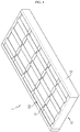
FIG. 1 is a diagram for illustrating a battery pack according to an embodiment of the present disclosure, andFIG. 2 is a diagram showing the battery pack ofFIG. 1 , from which a partial beam base of a case beam is excluded. - Referring to
FIGS. 1 and2 , abattery pack 1 may be provided at a vehicle as a fuel source for the vehicle. As an example, thebattery pack 1 may be provided at an electric vehicle, a hybrid vehicle, or any other vehicle that may use thebattery pack 1 as a fuel source. In addition, thebattery pack 1 may be provided at other devices, instruments or facilities such as an energy storage system using a secondary battery, in addition to the vehicle. - The
battery pack 1 may include acase beam 10 and abattery module 50. - The
case beam 10 forms the appearance of thebattery pack 1 and may accommodate at least onebattery module 50, explained later. Here, the at least onebattery module 50, explained later, may be mounted to thecase beam 10 through sliding insertion. The sliding insertion will be described in more detail in the following description. - The
case beam 10 may include abeam base 12 and abeam bridge 14. - The
beam base 12 is elongated along a front and rear direction of thecase beam 10 and may be provided in a pair so that the pair ofbeam bases 12 are spaced apart from each other by a predetermined length in the right and left direction. Inside the pair ofbeam bases 12, a coolingchannel 15 in which a coolant flows may be provided. - The
beam bridge 14 connects the pair ofbeam bases 12 and may be provided in plural. The plurality of beam bridges 14 may be spaced apart from each other by a predetermined distance in the front and rear direction of thecase beam 10. - At least one
battery module 50, explained later, or a plurality ofbattery modules 50 in this embodiment, may be mounted between the plurality of beam bridges 14 through sliding insertion. In other words, eachbattery module 50 may be slid along the right and left direction between the beam bridges 14 and fixedly mounted between the beam bridges 14. - The cooling
channel 15 may be formed in eachbeam bridge 14. - The cooling
channel 15 is formed along the longitudinal direction of thebeam bridge 14 and may be disposed before and after the at least onebattery module 50, explained later. In addition, the coolingchannel 15 is also provided in thebeam base 12 and thus may be disposed around thebattery module 50. - A coolant capable of cooling the at least one
battery module 50, explained later, may flow in the coolingchannel 15. The coolant may be supplied from a coolant circulating unit (not shown) that may be separately mounted to thecase beam 10 or integrally mounted to thecase beam 10. - At least one
battery module 50 or a plurality ofbattery modules 50 may be provided. Hereinafter, in this embodiment, it is assumed that a plurality of thebattery modules 50 are provided. The plurality ofbattery modules 50 may be mounted to thecase beam 10 through sliding insertion. - Seeing the process of mounting the plurality of
battery modules 50 in more detail, first, a worker or the like may couple any onebeam base 12 of thecase beam 10 to the plurality of beam bridges 14. - After that, the worker or the like may dispose the plurality of
battery modules 50 between the plurality of beam bridges 14 by sliding slide them between the plurality of beam bridges 14. - If the plurality of
battery modules 50 is completely slidably inserted, the worker or the like may package the plurality ofbattery modules 50 in thecase beam 10 by mounting theother beam base 12 of thecase beam 10. - As described above, in this embodiment, since the plurality of
battery modules 50 may be mounted to thecase beam 10 only by sliding insertion without a separate bolting structure, the manufacturing efficiency of thebattery pack 1 may be significantly increased. - Hereinafter, the plurality of
battery modules 50 will be described in more detail. -
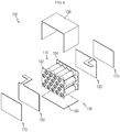
FIG. 3 is a diagram for illustrating a battery module of the battery pack ofFIG. 1 , andFIG. 4 is an exploded perspective view showing the battery module ofFIG. 3 . - Referring to
FIGS. 3 and4 , eachbattery module 50 may include abattery cell assembly 100, abottom case 200, anupper case 300 and acooling unit 500. - At least one
battery cell assembly 100 or a plurality ofbattery cell assemblies 100 may be provided. Hereinafter, in this embodiment, it is assumed that a plurality ofbattery cell assemblies 100 are provided. - Hereinafter, the plurality of
battery cell assemblies 100 will be described in more detail with reference toFIGS. 5 and6 . -
FIG. 5 is a perspective view showing a battery cell assembly of the battery module ofFIG. 4 , andFIG. 6 is an exploded perspective view showing the battery cell assembly ofFIG. 5 . - Referring to
FIGS. 5 and6 , eachbattery cell assembly 100 may include abattery cell 110, acell housing 130, a pair ofbus bars 150 and a pair ofheat conduction pads 170. - The
battery cell 110 may be a cylindrical secondary battery, and at least onebattery cell 110 or a plurality ofbattery cells 110 may be provided. Hereinafter, in this embodiment, it is assumed that a plurality ofbattery cells 110 are provided. - The plurality of
battery cells 110 may be disposed to be stacked on one another. Specifically, eachbattery cell 110 may be disposed to lie down in a horizontal direction parallel to the front and rear direction of the plurality ofbattery cell assemblies 100. In detail, the plurality ofbattery cells 110 may be disposed to lie down in the horizontal direction and stacked in the vertical direction. - In this embodiment, since the plurality of
battery cells 110 are disposed to lie down in the horizontal direction, considering that thebattery pack 1 is generally disposed below a passenger when being mounted to a vehicle, the safety of the passenger located above the plurality ofbattery cells 110 may be relatively secured when an event such as ignition or explosion occurs. - The
cell housing 130 is for covering the plurality ofbattery cells 110 and may include afront housing 132, arear housing 134 and abody housing 136. - The
front housing 132 may cover a front side of the plurality ofbattery cells 110. Therear housing 134 may cover a rear side of the plurality ofbattery cells 110. - The
body housing 136 may cover the plurality ofbattery cells 110 between thefront housing 132 and therear housing 134. Specifically, thebody housing 136 may cover an upper side, a lower side and both lateral sides of the plurality ofbattery cells 110 and may include ahousing cover 138 and ahousing base 139. - The
housing cover 138 may cover the upper side and both lateral sides of the plurality ofbattery cells 110. Thehousing base 139 may cover the lower side of the plurality ofbattery cells 110. - The pair of
bus bars 150 are mounted to front and rear sides of thecell housing 130, respectively, and may be electrically connected to the plurality ofbattery cells 110. Any one of the pair ofbus bars 150 is mounted to the front side of thefront housing 132 and may be electrically connected to any one of positive and negative electrodes of the plurality ofbattery cells 110. The other of the pair ofbus bars 150 is mounted to the rear side of therear housing 134 and may be electrically connected to the other of the positive and negative electrodes of the plurality ofbattery cells 110. - The pair of
heat conduction pads 170 are for transferring heat of the plurality ofbattery cells 110 and may be mounted to the front and rear sides of the pair ofbus bars 150, respectively. The pair ofheat conduction pads 170 may improve the cooling performance when cooling the plurality ofbattery cells 110. - Referring to
FIGS. 3 and4 again, thebottom case 200 may accommodate the plurality ofbattery cell assemblies 100. To this end, thebottom case 200 may have an accommodation space for accommodating the plurality ofbattery cell assemblies 100. - The
upper case 300 is mounted to the upper side of thebottom case 200 and may expose a part of the upper side, a part of the front side and a part of the rear side of the plurality ofbattery cell assemblies 100. This is in order to dispose the plurality of coolingunits 500 nearer to the cooling channel 15 (seeFIGS. 1 and2 ) of the case beam 10 (seeFIGS. 1 and2 ), explained later. - The
cooling unit 500 is for improving the cooling performance of the plurality ofbattery cell assemblies 100 and may cover the exposed parts of the plurality ofbattery cell assemblies 100 and may be disposed in contact with or adjacent to thecase beam 10. - Accordingly, the
cooling unit 500 may be located close to the cooling channel 15 (seeFIGS. 1 and2 ) of the beam bridge 14 (seeFIGS. 1 and2 ) of the case beam 10 (seeFIGS. 1 and2 ) and disposed in contact with thebeam bridge 14 of thecase beam 10. - The
cooling unit 500 may be provided in plural. The plurality of coolingunits 500 may be spaced apart from each other by a predetermined distance along the right and left direction of theupper case 300. - Hereinafter, the plurality of cooling
units 500 will be described in more detail with reference toFIGS. 7 to 9 . -
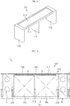
FIG. 7 is a perspective view showing a cooling unit of the battery module ofFIG. 4 ,FIG. 8 is a cross-sectioned view showing the cooling unit ofFIG. 7 , andFIG. 9 is a perspective view showing a base body of the cooling unit ofFIG. 7 . - Referring to
FIGS. 7 to 9 , each coolingunit 500 may include abase frame 510, aphase change material 530 and acover frame 550. - The
base frame 510 is made of a metal with a high thermal conductivity and may be inserted into theupper case 300 and come into contact with the exposed parts of the plurality ofbattery cell assemblies 100. Thebase frame 510 may include abase body 512, abase bridge 516 and apartitioning bridge 518. - The
base body 512 may cover a part of the upper side of the plurality ofbattery cell assemblies 100. Thebase body 512 may have anaccommodation groove 514. Theaccommodation groove 514 is provided at the upper surface of thebase body 512 and may accommodate thephase change material 530, explained later. - The base bridges 516 may be provided in a pair and disposed at both ends of the
base body 512 in the front and rear direction, respectively. The pair of base bridges 516 may cover a part of the front side and a part of the rear side of the plurality ofbattery cell assemblies 100. - The
partitioning bridge 518 is provided between the pair ofbase bridges 516 and may partition thebattery cells 100 facing each other in the front and rear direction of theupper case 300, in the plurality ofbattery cell assemblies 100. - Specifically, the
partitioning bridge 518 protrudes from the lower side of thebase body 512 to be disposed between thebattery cells 100 facing each other in the front and rear direction of theupper case 300 and may be disposed in contact with the facingbattery cell assemblies 100 in order to improve the heat transfer efficiency. - The
phase change material 530 is a material capable of improving the cooling performance of the plurality ofbattery cell assemblies 100 and may be accommodated above thebase frame 510. Specifically, thephase change material 530 may be filled in theaccommodation groove 514 of thebase body 512. - The
phase change material 530 may be provided as a material that may change from a gas to a liquid or from a liquid to a gas through a phase change. For example, thephase change material 530 may be provided as a material with as a low boiling point, for example a Novec™-based material. - The
cover frame 550 may be made of a metal material with high thermal conductivity, similar to thebase frame 510, and may be mounted to the upper side of thebase frame 510. Specifically, thecover frame 550 may be mounted to the upper side of thebase body 512 to seal theaccommodation groove 514 that accommodates thephase change material 530. - The
cover frame 550 may protrude by a predetermined length along the front and rear direction of theupper case 300. The protruding portion of thecover frame 550 may be placed on the upper side of the beam bridge 14 (seeFIGS. 1 and2 ) of the case beam 10 (seeFIGS. 1 and2 ). Accordingly, thecooling unit 500 may be more stably fixed to thecase beam 10 and may enhance the thermal conductivity to thecase beam 10. - Hereinafter, the process of cooling the battery pack 1 (see
FIGS. 1 and2 ) through thecooling unit 500 according to this embodiment will be described in more detail. -
FIG. 10 is a diagram for illustrating a process of cooling the battery pack ofFIG. 1 . - Referring to
FIG. 10 , when the temperature of thebattery cell assemblies 100 of thebattery pack 1 rises, the heat generated in thebattery cell assemblies 100 may be transferred to thecooling unit 500 first. - First, since the
base bridge 516 of thecooling unit 500 is located near the coolingchannel 15 of thecase beam 10, it is possible to cool thebattery cell assemblies 100. - In addition, the
phase change material 530 of thecooling unit 500 disposed at the upper side of thebattery cell assemblies 100 may guide cooling of thebattery cell assemblies 100 through evaporation and condensation. - Specifically, when the heat generated from the
battery cell assemblies 100 is transferred to thebase body 512 of thecooling unit 500, thephase change material 530 changes from a liquid to a the gas by means of the phase change to lower the temperature of thebattery cell assemblies 100. In addition, if the temperature of thecover frame 550 in contact with thecase beam 10 having the coolingchannel 15 is lowered, thephase change material 530 may change its phase again from a gas to a liquid. - According to this mechanism, the
phase change material 530 may improve the cooling performance of thebattery cell assemblies 100 by repeating evaporation and condensation depending on the temperatures of thebattery cell assemblies 100 and thecover frame 550. - As described above, the
battery module 50 according to this embodiment and thebattery pack 1 including thebattery module 50 may ensure the cooling performance by means of thecooling unit 500 including thephase change material 530 and having a simple structure, without any conventional complicated structure such as cooling tubes and cooling pumps. - Accordingly, the
battery module 50 according to this embodiment and thebattery pack 1 including thebattery module 50 may maximize the space efficiency of thebattery cells 110 relatively. - Thus, the
battery module 50 according to this embodiment and thebattery pack 1 including thebattery module 50 may improve the energy density of thebattery cells 110 through thecooling unit 500 and implement a simpler cooling structure. - While the embodiments of the present disclosure have been shown and described, it should be understood that the present disclosure is not limited to the specific embodiments described, and that various changes and modifications can be made within the scope of the present disclosure by those skilled in the art, and these modifications should not be understood individually from the technical ideas and views of the present disclosure.
Claims (15)
- A battery module (50), comprising:a plurality of battery cell assemblies (100), each having at least one battery cell (110);a bottom case (200) configured to accommodate the plurality of battery cell assemblies (100);an upper case (300) mounted to an upper side of the bottom case;a cooling unit (500) having a phase change material (530) for cooling the plurality of battery cell assemblies (100),characterized in thatthe upper case (300) is mounted to the upper side of the bottom case (200) to expose a part of an upper side, a part of a front side and a part of a rear side of the plurality of battery cell assemblies (100); andthe cooling unit (500) is configured to cover the exposed parts of the plurality of battery cell assemblies (100).
- The battery module (50) according to claim 1, wherein the cooling unit (500) includes:a base frame (510) inserted into the upper case (300) to come into contact with the exposed parts of the plurality of battery cell assemblies (100);the phase change material (530) accommodated at an upper side of the base frame (510); anda cover frame (550) mounted to an upper side of the base frame (510) to seal the phase change material (530).
- The battery module (50) according to claim 2, wherein the base frame (510) includes:a base body (512) configured to cover a part of the upper side of the plurality of battery cell assemblies (100) and having an accommodation groove (514) for accommodating the phase change material (530);base bridges (516) provided at both ends of the base body (512) to cover a part of the front side and a part of the rear side of the plurality of battery cell assemblies (100); anda partitioning bridge (518) provided between the base bridges (516) to partition battery cell assemblies (100) that face each other.
- The battery module (50) according to claim 3,
wherein the partitioning bridge (518) is disposed between the facing battery cell assemblies (100) and comes into contact with the facing battery cell assemblies (100). - The battery module (50) according to claim 2,
wherein the cover frame (550) protrudes along a front and rear direction of the upper case (300) by a predetermined length. - The battery module (50) according to claim 1,
wherein the cooling unit (500) is provided in plural, and
wherein the plurality of cooling units (500) are disposed to be spaced apart from each other by a predetermined distance along a right and left direction of the upper case (300). - The battery module (50) according to claim 1,
wherein each of the plurality of battery cell assemblies (100) includes:a plurality of battery cells (110) stacked on one another;a cell housing (130) configured to cover the plurality of battery cells (110);a pair of bus bars (150) mounted to a front side and a rear side of the cell housing (130) and electrically connected to the plurality of battery cells (110); anda pair of heat conduction pads (170) respectively mounted to the pair of bus bars (150) to transfer heat of the plurality of battery cells (110). - The battery module (50) according to claim 7,
wherein each of the battery cells (110) is disposed to lie down in a horizontal direction parallel to a front and rear direction of the plurality of battery cell assemblies (100). - The battery module (50) according to claim 7,
wherein the plurality of battery cells (110) are cylindrical secondary batteries. - The battery module (50) according to claim 7, wherein the cell housing (130) includes:a front housing (132) configured to cover a front side of the plurality of battery cells (110);a rear housing (134) configured to cover a rear side of the plurality of battery cells (110); anda body housing (136) provided between the front housing (132) and the rear housing (134) to cover the plurality of battery cells (110).
- The battery module (50) according to claim 10,
wherein the pair of bus bars (150) are respectively mounted to the front housing (132) and the rear housing (134). - A battery pack (1), comprising:at least one battery module (50) defined in claim 1; anda case beam (10) into which the at least one battery module (50) is inserted by sliding.
- The battery pack (1) according to claim 12,
wherein the case beam (10) has a cooling channel (15) through which a coolant for cooling the at least one battery module (50) flows. - The battery pack (1) according to claim 13,
wherein the cooling unit (500) is disposed in contact with the case beam (10) near the cooling channel (15). - A vehicle, comprising at least one battery pack (1) defined in claim 12.
Priority Applications (1)
| Application Number | Priority Date | Filing Date | Title |
|---|---|---|---|
| PL18767865T PL3467902T3 (en) | 2017-03-15 | 2018-02-12 | Battery module, battery pack including battery module, and vehicle including battery pack |
Applications Claiming Priority (2)
| Application Number | Priority Date | Filing Date | Title |
|---|---|---|---|
| KR1020170032572A KR102057232B1 (en) | 2017-03-15 | 2017-03-15 | Battery module, battery pack comprising the battery module and vehicle comprising the battery pack |
| PCT/KR2018/001818 WO2018169216A1 (en) | 2017-03-15 | 2018-02-12 | Battery module, battery pack comprising battery module, and vehicle comprising battery pack |
Publications (3)
| Publication Number | Publication Date |
|---|---|
| EP3467902A1 EP3467902A1 (en) | 2019-04-10 |
| EP3467902A4 EP3467902A4 (en) | 2019-08-28 |
| EP3467902B1 true EP3467902B1 (en) | 2020-04-22 |
Family
ID=63522367
Family Applications (1)
| Application Number | Title | Priority Date | Filing Date |
|---|---|---|---|
| EP18767865.1A Active EP3467902B1 (en) | 2017-03-15 | 2018-02-12 | Battery module, battery pack including battery module, and vehicle including battery pack |
Country Status (7)
| Country | Link |
|---|---|
| US (1) | US11024896B2 (en) |
| EP (1) | EP3467902B1 (en) |
| JP (1) | JP6762383B2 (en) |
| KR (1) | KR102057232B1 (en) |
| CN (2) | CN207967112U (en) |
| PL (1) | PL3467902T3 (en) |
| WO (1) | WO2018169216A1 (en) |
Families Citing this family (13)
| Publication number | Priority date | Publication date | Assignee | Title |
|---|---|---|---|---|
| KR102057232B1 (en) * | 2017-03-15 | 2019-12-18 | 주식회사 엘지화학 | Battery module, battery pack comprising the battery module and vehicle comprising the battery pack |
| US20190273295A1 (en) * | 2018-03-05 | 2019-09-05 | Anhui Xinen Technology Co., Ltd. | Regenerative solid-solid phase change cooling for an energy storage device |
| CN110504398A (en) | 2019-09-23 | 2019-11-26 | 常州格力博有限公司 | A kind of battery pack |
| KR20210070762A (en) * | 2019-12-05 | 2021-06-15 | 주식회사 엘지에너지솔루션 | Battery pack comprising thermal progagation blocking member |
| JP2021140863A (en) * | 2020-03-02 | 2021-09-16 | アイシン軽金属株式会社 | Battery pack structure |
| KR20220014575A (en) * | 2020-07-29 | 2022-02-07 | 주식회사 엘지에너지솔루션 | Battery pack and method of manufacturing the same |
| FR3113193B1 (en) * | 2020-07-30 | 2022-11-25 | Faurecia Systemes Dechappement | Electric battery and associated vehicle |
| DE102020126302A1 (en) * | 2020-10-07 | 2022-04-07 | Volkswagen Aktiengesellschaft | Cell module housing for accommodating a battery module |
| US20220209348A1 (en) * | 2020-12-31 | 2022-06-30 | Samsung Sdi Co., Ltd. | Battery module |
| KR20230018233A (en) * | 2021-07-29 | 2023-02-07 | 주식회사 엘지에너지솔루션 | Battery module and battery pack including the same |
| EP4354597A1 (en) * | 2021-12-27 | 2024-04-17 | LG Energy Solution, Ltd. | Battery pack, and energy storage system and vehicle comprising battery pack |
| KR20240016534A (en) * | 2022-07-29 | 2024-02-06 | 인지컨트롤스 주식회사 | Battery module |
| KR20240037011A (en) * | 2022-09-14 | 2024-03-21 | 에스케이온 주식회사 | Battery module and Battery pack including the same |
Family Cites Families (35)
| Publication number | Priority date | Publication date | Assignee | Title |
|---|---|---|---|---|
| JP2000090976A (en) * | 1998-09-11 | 2000-03-31 | Ngk Insulators Ltd | Lithium secondary battery module |
| JP2001035450A (en) | 1999-07-19 | 2001-02-09 | Toyota Motor Corp | Rectangular battery |
| JP2001255085A (en) * | 2000-03-14 | 2001-09-21 | Hitachi Ltd | Variable conductance heat pipe |
| JP2006092935A (en) | 2004-09-24 | 2006-04-06 | Teijin Pharma Ltd | Battery pack |
| KR100905392B1 (en) | 2006-04-03 | 2009-06-30 | 주식회사 엘지화학 | Battery Pack Comprising Combined Temperature-controlling System |
| JP2008204762A (en) | 2007-02-20 | 2008-09-04 | Toyota Motor Corp | Power source device |
| FR2924857B1 (en) | 2007-12-06 | 2014-06-06 | Valeo Equip Electr Moteur | ELECTRICAL SUPPLY DEVICE COMPRISING A RECEPTION UNIT FOR ULTRA CAPACITY STORAGE UNITS |
| JP5330810B2 (en) * | 2008-11-18 | 2013-10-30 | 株式会社日立製作所 | Battery box for storing battery module and railcar equipped with the same |
| KR101029837B1 (en) | 2009-01-06 | 2011-04-15 | 주식회사 엘지화학 | Novel battery module and medium and large battery packs comprising the same |
| JP2012524998A (en) | 2009-04-21 | 2012-10-18 | ユナ ティーアンドイー カンパニーリミテッド | Solar module with cooling device and method of manufacturing the same |
| US20110293986A1 (en) | 2009-11-25 | 2011-12-01 | Katsumi Kozu | Battery module |
| KR101136310B1 (en) * | 2010-06-07 | 2012-04-19 | 에스비리모티브 주식회사 | Battery pack |
| CN201829580U (en) * | 2010-06-07 | 2011-05-11 | 高宾 | Multifunctional module of universal lithium battery |
| KR101084224B1 (en) * | 2010-06-10 | 2011-11-17 | 에스비리모티브 주식회사 | Battery pack |
| JP5149945B2 (en) | 2010-09-03 | 2013-02-20 | 日本特殊陶業株式会社 | Gas sensor and manufacturing method thereof |
| KR101293211B1 (en) | 2010-12-28 | 2013-08-05 | 주식회사 엘지화학 | Battery module container, battery module temperature control apparatus and power storage system having them |
| KR20120111686A (en) | 2011-04-01 | 2012-10-10 | 인지컨트롤스 주식회사 | Temperature controller for battery of electricvehicle |
| JP5726605B2 (en) * | 2011-04-12 | 2015-06-03 | 日立オートモティブシステムズ株式会社 | Battery block and power storage device incorporating battery pack |
| KR101355961B1 (en) * | 2011-04-25 | 2014-02-03 | 주식회사 엘지화학 | Apparatus for containing battery pack and apparatus for cooling power storage battery pack using it |
| KR20130090100A (en) | 2012-02-03 | 2013-08-13 | 삼성에스디아이 주식회사 | Cell holder |
| CN202487724U (en) * | 2012-02-10 | 2012-10-10 | 新普科技股份有限公司 | Battery assembly, battery module and heat-dissipating seat thereof |
| JP5037740B1 (en) * | 2012-05-29 | 2012-10-03 | 日立マクセルエナジー株式会社 | Battery case and battery pack including the same |
| JP5978847B2 (en) * | 2012-08-09 | 2016-08-24 | 株式会社豊田自動織機 | Battery pack |
| CN104241730B (en) * | 2013-06-13 | 2018-03-20 | 南京德朔实业有限公司 | Battery pack with heat dissipation system |
| KR101575422B1 (en) | 2013-12-11 | 2015-12-07 | 현대자동차주식회사 | Battery for vehicle |
| KR101586668B1 (en) | 2013-12-27 | 2016-01-19 | 주식회사 엘지화학 | Battery Module Assembly Including Sub-Modules Inside |
| JP2015153743A (en) * | 2014-02-19 | 2015-08-24 | 日立建機株式会社 | Power storage device, and work machine mounting the same |
| KR101649154B1 (en) | 2014-02-24 | 2016-08-18 | 엘지전자 주식회사 | Battery Pack |
| KR101778667B1 (en) | 2015-03-09 | 2017-09-26 | 주식회사 엘지화학 | Battery Module Comprising Cooling plates |
| US11302973B2 (en) | 2015-05-19 | 2022-04-12 | Ford Global Technologies, Llc | Battery assembly with multi-function structural assembly |
| US11258104B2 (en) | 2015-06-30 | 2022-02-22 | Faraday & Future Inc. | Vehicle energy-storage systems |
| US10115943B2 (en) * | 2015-11-02 | 2018-10-30 | Korea Institute Of Energy Research | Battery packing module and battery pack |
| CN205810904U (en) * | 2016-06-12 | 2016-12-14 | 北京长城华冠汽车科技股份有限公司 | A kind of temperature keeping battery case and the automobile including this temperature keeping battery case |
| TWM533364U (en) * | 2016-08-25 | 2016-12-01 | Formosa Electronic Ind Inc | Sliding stack structure of energy-storage battery module |
| KR102057232B1 (en) * | 2017-03-15 | 2019-12-18 | 주식회사 엘지화학 | Battery module, battery pack comprising the battery module and vehicle comprising the battery pack |
-
2017
- 2017-03-15 KR KR1020170032572A patent/KR102057232B1/en active IP Right Grant
-
2018
- 2018-02-12 WO PCT/KR2018/001818 patent/WO2018169216A1/en unknown
- 2018-02-12 JP JP2018567729A patent/JP6762383B2/en active Active
- 2018-02-12 US US16/307,682 patent/US11024896B2/en active Active
- 2018-02-12 EP EP18767865.1A patent/EP3467902B1/en active Active
- 2018-02-12 PL PL18767865T patent/PL3467902T3/en unknown
- 2018-03-15 CN CN201820357106.0U patent/CN207967112U/en active Active
- 2018-03-15 CN CN201810213101.5A patent/CN108630847B/en active Active
Non-Patent Citations (1)
| Title |
|---|
| None * |
Also Published As
| Publication number | Publication date |
|---|---|
| CN108630847A (en) | 2018-10-09 |
| JP6762383B2 (en) | 2020-09-30 |
| PL3467902T3 (en) | 2020-12-14 |
| EP3467902A4 (en) | 2019-08-28 |
| KR20180105465A (en) | 2018-09-28 |
| KR102057232B1 (en) | 2019-12-18 |
| WO2018169216A1 (en) | 2018-09-20 |
| CN207967112U (en) | 2018-10-12 |
| JP2019525393A (en) | 2019-09-05 |
| CN108630847B (en) | 2020-06-09 |
| US11024896B2 (en) | 2021-06-01 |
| US20190221901A1 (en) | 2019-07-18 |
| EP3467902A1 (en) | 2019-04-10 |
Similar Documents
| Publication | Publication Date | Title |
|---|---|---|
| EP3467902B1 (en) | Battery module, battery pack including battery module, and vehicle including battery pack | |
| EP3474345B1 (en) | Battery module, battery pack including the battery module, and automobile including the battery pack | |
| EP3460871B1 (en) | Battery module, battery pack including the battery module, and automobile including the battery pack | |
| US10892528B2 (en) | Battery module, battery pack comprising battery module, and vehicle comprising battery pack | |
| EP3780250B1 (en) | Battery module, battery pack comprising same battery module, and vehicle comprising same battery pack | |
| KR101453780B1 (en) | Battery module container, battery module temperature control apparatus and power storage system having them | |
| EP3291360B1 (en) | Battery pack and vehicle including such battery pack | |
| CN210926080U (en) | Battery unit assembly, battery module, battery pack, and vehicle | |
| EP3696905B1 (en) | Battery module and battery pack comprising same battery module | |
| KR20170121555A (en) | Battery pack and vehicle comprising the battery pack | |
| US11764425B2 (en) | Battery module, battery pack including same battery module, and vehicle including same battery pack | |
| EP3731336A1 (en) | Battery module, battery rack comprising battery module, and power storage device comprising battery rack | |
| KR102067709B1 (en) | Battery module, battery pack comprising the battery module and vehicle comprising the battery pack | |
| KR20170043306A (en) | Battery module, battery pack comprising the battery module and vehicle comprising the battery pack |
Legal Events
| Date | Code | Title | Description |
|---|---|---|---|
| STAA | Information on the status of an ep patent application or granted ep patent |
Free format text: STATUS: THE INTERNATIONAL PUBLICATION HAS BEEN MADE |
|
| PUAI | Public reference made under article 153(3) epc to a published international application that has entered the european phase |
Free format text: ORIGINAL CODE: 0009012 |
|
| STAA | Information on the status of an ep patent application or granted ep patent |
Free format text: STATUS: REQUEST FOR EXAMINATION WAS MADE |
|
| 17P | Request for examination filed |
Effective date: 20190107 |
|
| AK | Designated contracting states |
Kind code of ref document: A1 Designated state(s): AL AT BE BG CH CY CZ DE DK EE ES FI FR GB GR HR HU IE IS IT LI LT LU LV MC MK MT NL NO PL PT RO RS SE SI SK SM TR |
|
| AX | Request for extension of the european patent |
Extension state: BA ME |
|
| A4 | Supplementary search report drawn up and despatched |
Effective date: 20190731 |
|
| RIC1 | Information provided on ipc code assigned before grant |
Ipc: H01M 2/20 20060101ALI20190725BHEP Ipc: H01M 10/613 20140101ALI20190725BHEP Ipc: H01M 2/10 20060101AFI20190725BHEP Ipc: H01M 10/643 20140101ALI20190725BHEP Ipc: H01M 10/625 20140101ALI20190725BHEP Ipc: H01M 10/6569 20140101ALI20190725BHEP Ipc: H01M 10/655 20140101ALI20190725BHEP Ipc: H01M 10/6556 20140101ALI20190725BHEP |
|
| GRAP | Despatch of communication of intention to grant a patent |
Free format text: ORIGINAL CODE: EPIDOSNIGR1 |
|
| STAA | Information on the status of an ep patent application or granted ep patent |
Free format text: STATUS: GRANT OF PATENT IS INTENDED |
|
| DAV | Request for validation of the european patent (deleted) | ||
| DAX | Request for extension of the european patent (deleted) | ||
| INTG | Intention to grant announced |
Effective date: 20191220 |
|
| GRAS | Grant fee paid |
Free format text: ORIGINAL CODE: EPIDOSNIGR3 |
|
| GRAA | (expected) grant |
Free format text: ORIGINAL CODE: 0009210 |
|
| STAA | Information on the status of an ep patent application or granted ep patent |
Free format text: STATUS: THE PATENT HAS BEEN GRANTED |
|
| AK | Designated contracting states |
Kind code of ref document: B1 Designated state(s): AL AT BE BG CH CY CZ DE DK EE ES FI FR GB GR HR HU IE IS IT LI LT LU LV MC MK MT NL NO PL PT RO RS SE SI SK SM TR |
|
| REG | Reference to a national code |
Ref country code: CH Ref legal event code: EP |
|
| REG | Reference to a national code |
Ref country code: DE Ref legal event code: R096 Ref document number: 602018004015 Country of ref document: DE |
|
| REG | Reference to a national code |
Ref country code: IE Ref legal event code: FG4D |
|
| REG | Reference to a national code |
Ref country code: AT Ref legal event code: REF Ref document number: 1261327 Country of ref document: AT Kind code of ref document: T Effective date: 20200515 |
|
| REG | Reference to a national code |
Ref country code: LT Ref legal event code: MG4D |
|
| REG | Reference to a national code |
Ref country code: NL Ref legal event code: MP Effective date: 20200422 |
|
| PG25 | Lapsed in a contracting state [announced via postgrant information from national office to epo] |
Ref country code: SE Free format text: LAPSE BECAUSE OF FAILURE TO SUBMIT A TRANSLATION OF THE DESCRIPTION OR TO PAY THE FEE WITHIN THE PRESCRIBED TIME-LIMIT Effective date: 20200422 Ref country code: NO Free format text: LAPSE BECAUSE OF FAILURE TO SUBMIT A TRANSLATION OF THE DESCRIPTION OR TO PAY THE FEE WITHIN THE PRESCRIBED TIME-LIMIT Effective date: 20200722 Ref country code: IS Free format text: LAPSE BECAUSE OF FAILURE TO SUBMIT A TRANSLATION OF THE DESCRIPTION OR TO PAY THE FEE WITHIN THE PRESCRIBED TIME-LIMIT Effective date: 20200822 Ref country code: GR Free format text: LAPSE BECAUSE OF FAILURE TO SUBMIT A TRANSLATION OF THE DESCRIPTION OR TO PAY THE FEE WITHIN THE PRESCRIBED TIME-LIMIT Effective date: 20200723 Ref country code: FI Free format text: LAPSE BECAUSE OF FAILURE TO SUBMIT A TRANSLATION OF THE DESCRIPTION OR TO PAY THE FEE WITHIN THE PRESCRIBED TIME-LIMIT Effective date: 20200422 Ref country code: PT Free format text: LAPSE BECAUSE OF FAILURE TO SUBMIT A TRANSLATION OF THE DESCRIPTION OR TO PAY THE FEE WITHIN THE PRESCRIBED TIME-LIMIT Effective date: 20200824 Ref country code: NL Free format text: LAPSE BECAUSE OF FAILURE TO SUBMIT A TRANSLATION OF THE DESCRIPTION OR TO PAY THE FEE WITHIN THE PRESCRIBED TIME-LIMIT Effective date: 20200422 Ref country code: LT Free format text: LAPSE BECAUSE OF FAILURE TO SUBMIT A TRANSLATION OF THE DESCRIPTION OR TO PAY THE FEE WITHIN THE PRESCRIBED TIME-LIMIT Effective date: 20200422 |
|
| REG | Reference to a national code |
Ref country code: AT Ref legal event code: MK05 Ref document number: 1261327 Country of ref document: AT Kind code of ref document: T Effective date: 20200422 |
|
| REG | Reference to a national code |
Ref country code: DE Ref legal event code: R079 Ref document number: 602018004015 Country of ref document: DE Free format text: PREVIOUS MAIN CLASS: H01M0002100000 Ipc: H01M0050200000 |
|
| PG25 | Lapsed in a contracting state [announced via postgrant information from national office to epo] |
Ref country code: LV Free format text: LAPSE BECAUSE OF FAILURE TO SUBMIT A TRANSLATION OF THE DESCRIPTION OR TO PAY THE FEE WITHIN THE PRESCRIBED TIME-LIMIT Effective date: 20200422 Ref country code: BG Free format text: LAPSE BECAUSE OF FAILURE TO SUBMIT A TRANSLATION OF THE DESCRIPTION OR TO PAY THE FEE WITHIN THE PRESCRIBED TIME-LIMIT Effective date: 20200722 Ref country code: HR Free format text: LAPSE BECAUSE OF FAILURE TO SUBMIT A TRANSLATION OF THE DESCRIPTION OR TO PAY THE FEE WITHIN THE PRESCRIBED TIME-LIMIT Effective date: 20200422 Ref country code: RS Free format text: LAPSE BECAUSE OF FAILURE TO SUBMIT A TRANSLATION OF THE DESCRIPTION OR TO PAY THE FEE WITHIN THE PRESCRIBED TIME-LIMIT Effective date: 20200422 |
|
| PG25 | Lapsed in a contracting state [announced via postgrant information from national office to epo] |
Ref country code: AL Free format text: LAPSE BECAUSE OF FAILURE TO SUBMIT A TRANSLATION OF THE DESCRIPTION OR TO PAY THE FEE WITHIN THE PRESCRIBED TIME-LIMIT Effective date: 20200422 |
|
| REG | Reference to a national code |
Ref country code: DE Ref legal event code: R097 Ref document number: 602018004015 Country of ref document: DE |
|
| PG25 | Lapsed in a contracting state [announced via postgrant information from national office to epo] |
Ref country code: EE Free format text: LAPSE BECAUSE OF FAILURE TO SUBMIT A TRANSLATION OF THE DESCRIPTION OR TO PAY THE FEE WITHIN THE PRESCRIBED TIME-LIMIT Effective date: 20200422 Ref country code: SM Free format text: LAPSE BECAUSE OF FAILURE TO SUBMIT A TRANSLATION OF THE DESCRIPTION OR TO PAY THE FEE WITHIN THE PRESCRIBED TIME-LIMIT Effective date: 20200422 Ref country code: AT Free format text: LAPSE BECAUSE OF FAILURE TO SUBMIT A TRANSLATION OF THE DESCRIPTION OR TO PAY THE FEE WITHIN THE PRESCRIBED TIME-LIMIT Effective date: 20200422 Ref country code: DK Free format text: LAPSE BECAUSE OF FAILURE TO SUBMIT A TRANSLATION OF THE DESCRIPTION OR TO PAY THE FEE WITHIN THE PRESCRIBED TIME-LIMIT Effective date: 20200422 Ref country code: CZ Free format text: LAPSE BECAUSE OF FAILURE TO SUBMIT A TRANSLATION OF THE DESCRIPTION OR TO PAY THE FEE WITHIN THE PRESCRIBED TIME-LIMIT Effective date: 20200422 Ref country code: RO Free format text: LAPSE BECAUSE OF FAILURE TO SUBMIT A TRANSLATION OF THE DESCRIPTION OR TO PAY THE FEE WITHIN THE PRESCRIBED TIME-LIMIT Effective date: 20200422 Ref country code: ES Free format text: LAPSE BECAUSE OF FAILURE TO SUBMIT A TRANSLATION OF THE DESCRIPTION OR TO PAY THE FEE WITHIN THE PRESCRIBED TIME-LIMIT Effective date: 20200422 Ref country code: IT Free format text: LAPSE BECAUSE OF FAILURE TO SUBMIT A TRANSLATION OF THE DESCRIPTION OR TO PAY THE FEE WITHIN THE PRESCRIBED TIME-LIMIT Effective date: 20200422 |
|
| PG25 | Lapsed in a contracting state [announced via postgrant information from national office to epo] |
Ref country code: SK Free format text: LAPSE BECAUSE OF FAILURE TO SUBMIT A TRANSLATION OF THE DESCRIPTION OR TO PAY THE FEE WITHIN THE PRESCRIBED TIME-LIMIT Effective date: 20200422 |
|
| PLBE | No opposition filed within time limit |
Free format text: ORIGINAL CODE: 0009261 |
|
| STAA | Information on the status of an ep patent application or granted ep patent |
Free format text: STATUS: NO OPPOSITION FILED WITHIN TIME LIMIT |
|
| 26N | No opposition filed |
Effective date: 20210125 |
|
| PG25 | Lapsed in a contracting state [announced via postgrant information from national office to epo] |
Ref country code: SI Free format text: LAPSE BECAUSE OF FAILURE TO SUBMIT A TRANSLATION OF THE DESCRIPTION OR TO PAY THE FEE WITHIN THE PRESCRIBED TIME-LIMIT Effective date: 20200422 |
|
| PG25 | Lapsed in a contracting state [announced via postgrant information from national office to epo] |
Ref country code: MC Free format text: LAPSE BECAUSE OF FAILURE TO SUBMIT A TRANSLATION OF THE DESCRIPTION OR TO PAY THE FEE WITHIN THE PRESCRIBED TIME-LIMIT Effective date: 20200422 |
|
| REG | Reference to a national code |
Ref country code: BE Ref legal event code: MM Effective date: 20210228 |
|
| PG25 | Lapsed in a contracting state [announced via postgrant information from national office to epo] |
Ref country code: CH Free format text: LAPSE BECAUSE OF NON-PAYMENT OF DUE FEES Effective date: 20210228 Ref country code: LI Free format text: LAPSE BECAUSE OF NON-PAYMENT OF DUE FEES Effective date: 20210228 Ref country code: LU Free format text: LAPSE BECAUSE OF NON-PAYMENT OF DUE FEES Effective date: 20210212 |
|
| PG25 | Lapsed in a contracting state [announced via postgrant information from national office to epo] |
Ref country code: IE Free format text: LAPSE BECAUSE OF NON-PAYMENT OF DUE FEES Effective date: 20210212 |
|
| PG25 | Lapsed in a contracting state [announced via postgrant information from national office to epo] |
Ref country code: BE Free format text: LAPSE BECAUSE OF NON-PAYMENT OF DUE FEES Effective date: 20210228 |
|
| PGFP | Annual fee paid to national office [announced via postgrant information from national office to epo] |
Ref country code: FR Payment date: 20230119 Year of fee payment: 6 |
|
| REG | Reference to a national code |
Ref country code: DE Ref legal event code: R081 Ref document number: 602018004015 Country of ref document: DE Owner name: LG ENERGY SOLUTION, LTD., KR Free format text: FORMER OWNER: LG CHEM, LTD., SEOUL, KR |
|
| PGFP | Annual fee paid to national office [announced via postgrant information from national office to epo] |
Ref country code: PL Payment date: 20230119 Year of fee payment: 6 Ref country code: GB Payment date: 20230119 Year of fee payment: 6 Ref country code: DE Payment date: 20230119 Year of fee payment: 6 |
|
| P01 | Opt-out of the competence of the unified patent court (upc) registered |
Effective date: 20230512 |
|
| PG25 | Lapsed in a contracting state [announced via postgrant information from national office to epo] |
Ref country code: CY Free format text: LAPSE BECAUSE OF FAILURE TO SUBMIT A TRANSLATION OF THE DESCRIPTION OR TO PAY THE FEE WITHIN THE PRESCRIBED TIME-LIMIT Effective date: 20200422 |
|
| PG25 | Lapsed in a contracting state [announced via postgrant information from national office to epo] |
Ref country code: HU Free format text: LAPSE BECAUSE OF FAILURE TO SUBMIT A TRANSLATION OF THE DESCRIPTION OR TO PAY THE FEE WITHIN THE PRESCRIBED TIME-LIMIT; INVALID AB INITIO Effective date: 20180212 |
|
| REG | Reference to a national code |
Ref country code: GB Ref legal event code: 732E Free format text: REGISTERED BETWEEN 20230824 AND 20230831 |