EP3467410A1 - A household refrigeration device comprising a drain pipe having a flexible extremity - Google Patents
A household refrigeration device comprising a drain pipe having a flexible extremity Download PDFInfo
- Publication number
- EP3467410A1 EP3467410A1 EP18189556.6A EP18189556A EP3467410A1 EP 3467410 A1 EP3467410 A1 EP 3467410A1 EP 18189556 A EP18189556 A EP 18189556A EP 3467410 A1 EP3467410 A1 EP 3467410A1
- Authority
- EP
- European Patent Office
- Prior art keywords
- pipe
- nozzle
- elasticity
- section
- refrigerating appliance
- Prior art date
- Legal status (The legal status is an assumption and is not a legal conclusion. Google has not performed a legal analysis and makes no representation as to the accuracy of the status listed.)
- Granted
Links
- 238000005057 refrigeration Methods 0.000 title claims description 16
- 239000000463 material Substances 0.000 claims abstract description 27
- 239000007788 liquid Substances 0.000 claims abstract description 14
- 238000007599 discharging Methods 0.000 claims abstract description 4
- 239000004033 plastic Substances 0.000 claims description 7
- 239000011810 insulating material Substances 0.000 claims description 5
- 229920001971 elastomer Polymers 0.000 claims description 3
- 239000000806 elastomer Substances 0.000 claims description 3
- 239000006260 foam Substances 0.000 claims description 2
- 230000008878 coupling Effects 0.000 description 12
- 238000010168 coupling process Methods 0.000 description 12
- 238000005859 coupling reaction Methods 0.000 description 12
- 238000013461 design Methods 0.000 description 6
- 238000004519 manufacturing process Methods 0.000 description 5
- 239000013536 elastomeric material Substances 0.000 description 2
- 238000002347 injection Methods 0.000 description 2
- 239000007924 injection Substances 0.000 description 2
- 238000009434 installation Methods 0.000 description 2
- XLYOFNOQVPJJNP-UHFFFAOYSA-N water Substances O XLYOFNOQVPJJNP-UHFFFAOYSA-N 0.000 description 2
- 230000004308 accommodation Effects 0.000 description 1
- 238000010276 construction Methods 0.000 description 1
- 238000011161 development Methods 0.000 description 1
- 230000005489 elastic deformation Effects 0.000 description 1
- 238000001746 injection moulding Methods 0.000 description 1
- 238000003780 insertion Methods 0.000 description 1
- 230000037431 insertion Effects 0.000 description 1
- 210000003127 knee Anatomy 0.000 description 1
- 230000014759 maintenance of location Effects 0.000 description 1
- 238000012545 processing Methods 0.000 description 1
- 239000002937 thermal insulation foam Substances 0.000 description 1
Images

Classifications
-
- F—MECHANICAL ENGINEERING; LIGHTING; HEATING; WEAPONS; BLASTING
- F25—REFRIGERATION OR COOLING; COMBINED HEATING AND REFRIGERATION SYSTEMS; HEAT PUMP SYSTEMS; MANUFACTURE OR STORAGE OF ICE; LIQUEFACTION SOLIDIFICATION OF GASES
- F25D—REFRIGERATORS; COLD ROOMS; ICE-BOXES; COOLING OR FREEZING APPARATUS NOT OTHERWISE PROVIDED FOR
- F25D21/00—Defrosting; Preventing frosting; Removing condensed or defrost water
- F25D21/14—Collecting or removing condensed and defrost water; Drip trays
-
- F—MECHANICAL ENGINEERING; LIGHTING; HEATING; WEAPONS; BLASTING
- F25—REFRIGERATION OR COOLING; COMBINED HEATING AND REFRIGERATION SYSTEMS; HEAT PUMP SYSTEMS; MANUFACTURE OR STORAGE OF ICE; LIQUEFACTION SOLIDIFICATION OF GASES
- F25D—REFRIGERATORS; COLD ROOMS; ICE-BOXES; COOLING OR FREEZING APPARATUS NOT OTHERWISE PROVIDED FOR
- F25D2321/00—Details or arrangements for defrosting; Preventing frosting; Removing condensed or defrost water, not provided for in other groups of this subclass
- F25D2321/14—Collecting condense or defrost water; Removing condense or defrost water
- F25D2321/146—Collecting condense or defrost water; Removing condense or defrost water characterised by the pipes or pipe connections
Definitions
- the invention relates to a household refrigerator with a housing by at least one receiving space is designed for food.
- the household refrigerator has an inner container which limits the receiving space through walls.
- the inner container has a nozzle for discharging liquid medium from the receiving space.
- the domestic refrigerator has a separate from the neck of the inner container drain pipe, which is designed as angled tube and which is coupled with a first pipe part with the nozzle.
- liquid such as water
- a nozzle is formed on the inner container, which allows the discharge of this liquid medium from the receiving space to the outside.
- a drain pipe is connected to this nozzle.
- Fig. 2 is shown in a schematic representation of a portion of a known household refrigeration appliance. It is shown a portion of an inner container 100. At this inner container an already mentioned nozzle 101 is formed, through which said liquid can drain. As in the presentation Fig. 2 can be seen, a separate drain pipe 102 is provided, which is an angle tube, and which is coupled with a first pipe part 103 to the nozzle 105. In the direction of a longitudinal axis A of the first pipe part 103, this first pipe part 103 is arranged overlapping the pipe 101. A second pipe part 104 of the one-piece drain pipe 102 is connected to the first pipe part 103 and arranged at an angle w1 thereto.
- a separate seal 105 may be arranged.
- the seal 105 is thus not arranged forwardly out of the first tube part 103, but positioned completely sunk therein.
- the drain pipe 102 is a plastic pipe in the known embodiments, so that both pipe parts 103 and 104 are dimensionally stable or rigid. As well as the neck 101 stationary and rigid is and thus an angle w2 is immutable, the position of the drain pipe 102 is fixed in the coupled state.
- the neck 101 is arranged differently or is oriented at a different angle w2, then the position of the entire rigid drain pipe 102 is always different. Due to the construction of the drainage pipe 102 in the domestic refrigeration appliance, it may then lead to the second pipe part 104 extending in an undesired direction, in particular deviating from a vertical orientation. This means that a longitudinal axis B of this second tube part 104 is not oriented vertically, but, for example, oriented obliquely to the vertical to the outside. This also means that an optionally connected drain hose 106 undesirably extends to the outside. The installation of the drain pipe 102 and the drain hose 106 is then difficult and may require additional considerable space. On the other hand, it is then also disadvantageous that undesired forces occur on the connection piece 101 due to any necessary positioning, so that it could possibly be damaged if it is attempted to spend the second pipe part 104 in the vertical direction.
- a drainpipe can be created, which can be positioned flexibly and needs-based with regard to the uses in a domestic refrigeration appliance.
- One aspect of the invention relates to a household refrigerating appliance with a housing in that at least one food receiving space is formed.
- the household refrigerator also has an inner container. The walls of the inner container limit the receiving space.
- the inner container also has a particularly integrally formed nozzle, which is designed for discharging liquid medium from the receiving space.
- the household refrigeration appliance also has a separate drain pipe to this nozzle.
- the drainpipe is coupled to the nozzle.
- the drain pipe has a first pipe section, whose material has a first elasticity, and the drain pipe has a, viewed along a longitudinal axis of the drain pipe, to the first pipe section different second pipe section, the material has a different second elasticity to the first elasticity.
- the drain pipe By such a configuration of the drain pipe, it is possible to set individual positions of at least pipe sections of the drain pipe to the nozzle, so that the drain pipe positionally can be used very flexible.
- this specifically trained drain pipe with different elastically deformable pipe sections a more flexible and needs-based coupling with the stationary nozzle is possible. Due to these different elasticities of the pipe sections, on the one hand a sufficient and reliable mechanical coupling with the nozzle can be made possible; on the other hand, an individual positional adjustment of the outlet pipe can also be set in the state arranged thereon.
- the drainpipe can also be configured sufficiently stable in sections, so that the dimensional stability is also individually high in sections.
- the first elasticity is greater than the second elasticity.
- the first pipe section is coupled to the nozzle or at an angle as the portion which has the kink or the elbow of the drain pipe, then a secure coupling with the nozzle on the one hand and a precise and continuous position adjustment on the other hand relative to Neck can be achieved.
- the first pipe section with the particularly greater material elasticity in the state mounted on the neck is arranged at least partially overlapping with the neck and at least partially not overlapping with the neck is arranged.
- the first pipe section is formed on both sides of this end edge exactly at the free end of the nozzle, so that the high elastic deformation is formed directly and adjacent to the connection of the nozzle and can be done.
- the first pipe section may also have a stiffer end ring at its end overlapping with the neck, so that axially spaced from the end edge of the neck then also a stiffer part of the drain pipe surrounds the neck.
- the first pipe section is coupled directly to the nozzle.
- the elastic part of the drain pipe is arranged directly on the nozzle and a position adjustment relative to the nozzle is then in the arranged state exactly and varied possible without undesirably large forces are transmitted to the nozzle.
- the drain pipe has a first pipe part which is coupled to the nozzle, and which is formed by the first pipe section.
- a direct coupling of the first pipe part is formed with this nozzle.
- the first tube part has, in particular, a cantilevered first tube end section, which is formed from an elastically deformable material having the first elasticity and which, in the coupled state with the neck, viewed in the direction of a connection axis between the first tube part and the neck, overlaps with this neck is arranged.
- the first Rohr turnedabterrorism is at least in the region of a free end of the nozzle, in particular arranged axially on both sides of the second end of the nozzle and thus arranged the second end axially across.
- the drainage tube which is designed in particular as an angle tube, otherwise rigid with respect to the second elasticity or dimensionally stable, as viewed as a whole be positioned so that the specific angular position between the nozzle and at least the first tube part is adjustable .
- a particular existing, formed at an angle to the first pipe part second pipe part of the drain pipe can be individually positioned, in particular preferably can be positioned vertically with a longitudinal axis of this second pipe part.
- the second pipe part is formed in particular by the second raw section.
- the first tube part has a second tube part end section, which, viewed in the direction of a longitudinal axis of the first tube part, is subsequently formed on the first tube section end section and of a material different from the first tube section end section.
- the material of the second pipe section end section is in particular of a different elasticity from the first elasticity, in particular the second elasticity.
- the first tube part has a second tube section end section, which is subsequently formed in the direction of a longitudinal axis of the first tube part to the first Rohr solveddabterrorism and the second Rohr solvedabrough is formed with a different elasticity to the first elasticity such that it is dimensionally stable.
- the advantages mentioned above are achieved and favors the overall stability of the drain pipe.
- the connection to a second pipe part of the drain pipe is then mechanically stable and allows the design as an angle tube is then very dimensionally stable or dimensionally stable.
- the first raw section itself, which forms only a part of the entire drain pipe, and which is in particular formed by the first pipe part, in turn formed in the direction of its longitudinal axis of different elastic regions.
- the more elastic region is formed on the end side of the drainage pipe.
- the more elastic region may also be formed between two less elastic regions, as viewed in the direction of the longitudinal axis of the drainage tube.
- the more elastic region may have a kinking point of the drainage pipe when the drainage pipe is designed as an angle pipe. Then, the greater deformability is formed exactly in the elbow of the drain pipe, in which case, in particular, the further region of the drain pipe, which is formed on this area in the direction of the longitudinal axis, are designed with greater elasticity, in particular of a dimensionally stable design.
- the material with the first elasticity of the first pipe section is formed in particular over the entire wall thickness (dimensioned perpendicular to the longitudinal axis of the pipe section) of the pipe section, so that an outer side of the first pipe section and an inner side of the first pipe section show this material.
- the drainage pipe can also have further pipe sections which are formed from a material having a third elasticity different from the first elasticity and the second elasticity.
- the first tube part has a second tube section end portion, which is viewed in the direction of a longitudinal axis of the first tube part formed on the first pipe section end portion and coupled in the coupled state of the first pipe part with the nozzle only the first pipe section end portion with the nozzle and with this is arranged overlapping. It is then formed in this embodiment, only this first pipe end portion as a coupling portion with the nozzle, whereby the flexible positioning of the drain pipe is favored relative to the nozzle again.
- the second Rohr solveddabites is formed of plastic.
- this one hand can be made very stiff and thus dimensionally stable, on the other hand formed with very low weight.
- the first pipe end portion of the first pipe part is formed without stiffening casing and / or without stiffening inner lining.
- the first pipe section end section has no deformability-impairing stiffening that would surround this elastically deformable material on the outside or would line on the inside.
- the deformation elasticity and thus the continuous individual position adjustment of the drain pipe at the nozzle is not hindered.
- the second pipe end portion of the first pipe part is not arranged in the direction of the longitudinal axis of the first pipe part overlapping with the nozzle, when the drain pipe is arranged in the coupled end state with the nozzle.
- the drain pipe is made in one piece.
- the drainpipe is manufactured as a one-piece molded part in a manufacturing process.
- the first pipe end portion is made of an elastomer having at least partially comprising material.
- the drain pipe is an at least 2K injection molded component.
- a 2-component injection-molded component can be produced in a very simple and extremely precise manner in one production process. Especially the design of the elastically deformable first Rohr solvedabterrorism and then different, more dimensionally stable second Rohr solvedabitess the first tube part is thereby made particularly accurate.
- the drain pipe has a second pipe part which is formed in particular by the second pipe section, and which is arranged at an angle greater than 0 ° and less than 180 ° to the first pipe part, and opens to the first pipe part.
- This angle is preferably between 90 ° and 140 °, in particular between 100 ° and 130 °.
- the second tube part in particular as a whole, is dimensionally stable or dimensionally stable. It is preferably made of plastic.
- the household refrigerator has a drain line, which is in particular a separate component to the drain pipe. It may also be provided a one-piece design.
- the drain line is connected to the drain pipe, in particular connected to the second pipe part. Thereby, the liquid medium, which drains from the receiving space via the nozzle into the drain pipe, then be forwarded by the drain pipe with the drain line.
- the drain line may be an elastic hose, but may also be a rigid pipe.
- the drain line opens into a machine room of the household refrigerator. It can be provided that this liquid medium is introduced into the machine room in a collecting tray or in a collecting container.
- a machine room of the household refrigerator preferably Components of a refrigeration cycle of the household refrigerating appliance are arranged, in particular a compressor is arranged, there arises in operation due to the compressor heat. This can be used to evaporate the liquid collected there, which is also introduced via the drain line.
- the drain pipe is arranged in a space between the inner container and a surrounding the inner container and to separate outer housing of the housing.
- the drain pipe is surrounded by a thermally insulating material, in particular an insulation foam, which is arranged in this intermediate space.
- a thermally insulating material in particular an insulation foam
- this drain pipe is additionally positionally fixed.
- the first pipe section end section since it is then also surrounded on the outside by this thermally insulating material and is virtually pressed against the connection piece. Additional fasteners to allow for retention at the neck are not required.
- the first Rohr nameddabites is dimensioned in its inner diameter so that it is smaller than an outer diameter of the nozzle.
- the overlapping coupling and the insertion of the nozzle into the first pipe section end section or the sliding over of the first pipe section end section over the pipe are made possible and, on the other hand, a firm and stable fit of the first pipe section end section on the pipe is made possible. Due to the elastic deformability of this first Rohr solvedabites also a certain expansion when pushing on the nozzle can be made possible and thus already achieved by this configuration, a rich and secure position on the socket.
- a drainage pipe for a household refrigeration appliance which is in particular designed as an angle tube and which has a first pipe section, the material has a first elasticity, and a along a longitudinal axis of the drain pipe to the first pipe section different second pipe section, whose material one to the first Elasticity has different second elasticity.
- the first elasticity is greater than the second elasticity.
- the first pipe section is coupled directly to the nozzle and arranged overlapping with the nozzle.
- a drainage pipe for a domestic refrigeration appliance which is in particular designed as an angle tube and which has a first pipe part, in particular for coupling with a nozzle of a components of the household refrigerating appliance, wherein the first pipe part has a cantilevered first pipe end portion, the an elastically deformable material is formed.
- the first Rohr solveddabterrorism is formed to overlap in the direction of a connecting axis of these components coupling with the nozzle.
- the first pipe part has a second pipe part end portion which is made integral with the first pipe part end portion of the first pipe part.
- the entire drainage pipe is produced in one piece and thus produced as a one-piece component in a production sequence, in particular an injection molding process.
- the first pipe end section is formed without stiffening casing and / or without stiffening inner lining.
- the first pipe section end section is in particular the exposed extension of the second pipe section end section.
- top, bottom, front, “rear”, “horizontal”, “vertical”, “depth direction”, “width direction”, “height direction”, etc. are the positions given when the device was used and disposed as intended and orientations indicated.
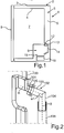
- Fig. 1 is shown in a simplified vertical sectional view of a household refrigerator 1, which is designed for storing and preserving food.
- That household refrigeration appliance 1 may be a refrigerator or a freezer or a fridge-freezer combination appliance his.
- the household refrigerating appliance 1 has a housing which has an outer housing 3 and an inner container 4.
- the outer housing 3 separate inner container 4 is received in the housing 3.
- a thermally insulating material 6 is introduced, for example, an insulating foam.
- the inner container 4 defines with its walls at least one receiving space 7, which may be, for example, a refrigerated compartment. Front side of the receiving space 7 is closed by a door 8 which is pivotally mounted on the housing 2.
- the household refrigerator 1 also has a machine room 9 in a lower rear area.
- a component of a refrigeration cycle of the household refrigerator 1 may be arranged.
- a component may for example be a compressor 10.
- a collecting tray 11 is also arranged in the machine room 9, which is preferably arranged adjacent to the compressor 10, for example, is arranged above the compressor 10.
- the inner container 1 has an integrally formed nozzle 12, so that in the receiving space 7 resulting liquid medium, such as water, from the receiving space 7 and from the inner container 4 can be derived out.
- the nozzle 12 is formed with a first end to a main body of the inner container 1 and formed with the opposite second, free end 19 cantilevered. This second end 19 represents an outlet or an end edge or an end edge of the nozzle 12.
- the domestic refrigerator 1 also has a drain pipe 13, which is a separate component to the nozzle 12 and which is directly coupled to the nozzle 12, as in Fig. 1 is shown.
- the household refrigerator 1 has a drain line 14, which is connected to the drain pipe 13 and a drain pipe 13 is a separate component.
- the drain line 14 opens into the machine room 9 and preferably into the collecting tray 11.
- the liquid accumulating in the receiving space 7 can thus be defined in the machine room 9 and preferably directed into the collecting tray 11, where the liquid due to the heat generated during operation of the compressor 10th can be evaporated.
- Fig. 3 is an embodiment of the drain pipe 13 is shown in a side view.
- the drain pipe 13 is in particular an angle pipe.
- the drain pipe 13 is preferably made in one piece, in particular as 2K injection molded component.
- This drain pipe 13 has a first pipe part 15, which here represents a first Rohhabites.
- the first tube part 15 has, in the direction of a longitudinal axis A, a first freely projecting tube dividing section 16 formed from an elastically deformable material.
- the material of the first pipe section end section here has a first elasticity.
- the first pipe part 15 has a second pipe section end section 17, which, viewed directly thereafter in the direction of the longitudinal axis A, opens onto the front, cantilevered first pipe section end section 16.
- the Rohr nameddabitese 16 and 17 are viewed in the direction of the longitudinal axis A contiguous to each other.
- the second pipe section end section 17 is formed with a different elasticity of its material to the first elasticity, in particular with a second elasticity which is greater for the first elasticity.
- the second pipe end portion 17 is dimensionally stable or dimensionally stable, and in particular made of plastic.
- the first pipe section end section 16 is preferably made of an elastomeric material, in particular completely as an elastomer.
- the drain pipe 13 also has a second pipe part 18, which here at an angle ⁇ to the first pipe part 15 opens. Viewed along the longitudinal axis A, the second tube part 18 forms a second tube section of the drainage tube 13.
- the material of the second tube part 18 is at least partially, in particular completely formed with a second elasticity, which is greater than the first elasticity.
- the second tube part 18 is preferably formed dimensionally stable or dimensionally stable and also made of plastic.
- the materials of the second pipe part 18 and the second pipe end portion 17 of the first pipe part 15 are made of the same plastic.
- the angle ⁇ is between 100 ° and 130 °.
- the first Rohr stolendabites 16 is considered here over its entire axial extent without additional stiffening sheath and / or formed without stiffening inner lining and thus designed in particular only as this preferably existing elastomeric material.
- the second pipe section end section 17 does not overlap the first pipe section end section 16 when viewed in the direction of the longitudinal axis A. at least not over the length provided for overlapping coupling with the stub 12.
- Fig. 4 a partial view of the household refrigerator 1 is shown.
- the inner container 4 is shown in the region of the nozzle 12, wherein here the drain pipe 15 is already shown in the coupled state with the nozzle 12.
- the nozzle 12 is arranged immersing in the first pipe section end portion 16 and immersing at most over such a length that corresponds to the extension of the first pipe section end portion 16 viewed in the direction of the longitudinal axis A.
- the axial overlap of the first pipe section end section 16 is formed such that the first pipe section end section 16 is designed to overlap both axially with the socket 12 and over the outlet or the second, free end of the socket 12, so that the first pipe section end portion 16 is also partially arranged non-overlapping with the nozzle 12.
- the preferably elastomeric part of the first pipe end portion 16 extends axially in the region of the free, second end 19 of the neck 12 then on both sides of this second end 19.
- the drain pipe 13 is an angle tube, that in addition to the above explanations or Instead, the area with the kink and thus the angle knee of a material with the first elasticity is formed, and thus is more elastic than the then adjacent on both sides further areas of the drain pipe 13.
- the on both sides Each of these flexible deformable center tube section subsequent areas are each completely stiffer.
- an adjoining area for example, as the above-explained first pipe part 15 is formed.
- the drain pipe 13 then has elastically deformable sections on two separate segments.
Landscapes
- Engineering & Computer Science (AREA)
- Chemical & Material Sciences (AREA)
- Combustion & Propulsion (AREA)
- Physics & Mathematics (AREA)
- Mechanical Engineering (AREA)
- Thermal Sciences (AREA)
- General Engineering & Computer Science (AREA)
- Removal Of Water From Condensation And Defrosting (AREA)
Abstract
Die Erfindung betrifft Haushaltskältegerät (1) mit einem Gehäuse (2), in dem zumindest ein Aufnahmeraum (7) für Lebensmittel ausgebildet ist, der durch Wände eines Innenbehälters (4) des Haushaltskältegeräts (1) begrenzt ist, wobei der Innenbehälter (4) einen Stutzen (12) zum Abführen von flüssigem Medium aus dem Aufnahmeraum (7) aufweist, und mit einem zum Stutzen (7) separaten Ablaufrohr (13), welches mit dem Stutzen (7) gekoppelt ist, wobei das Ablaufrohr (13) einen erste Rohrabschnitt aufweist, dessen Material eine erste Elastizität aufweist, und einen entlang einer Längsachse (A) des Ablaufrohrs (13) zum ersten Rohrabschnitt unterschiedlichen zweiten Rohrabschnitt aufweist, dessen Material eine zur ersten Elastizität unterschiedliche zweite Elastizität aufweist.The invention relates to household refrigerating appliance (1) with a housing (2) in which at least one receiving space (7) is formed for food, which is bounded by walls of an inner container (4) of the household refrigerating appliance (1), wherein the inner container (4) Stub (12) for discharging liquid medium from the receiving space (7), and with a nozzle (7) separate drain pipe (13) which is coupled to the nozzle (7), wherein the drain pipe (13) has a first pipe section whose material has a first elasticity and along a longitudinal axis (A) of the drain pipe (13) to the first pipe section has different second pipe section, the material has a different second elasticity to the first elasticity.
Description
Die Erfindung betrifft ein Haushaltskältegerät mit einem Gehäuse, indem zumindest ein Aufnahmeraum für Lebensmittel ausgebildet ist. Das Haushaltskältegerät weist einen Innenbehälter auf, der durch Wände den Aufnahmeraum begrenzt. Der Innenbehälter weist einen Stutzen zum Abführen von flüssigem Medium aus dem Aufnahmeraum auf. Darüber hinaus weist das Haushaltskältegerät ein zu dem Stutzen des Innenbehälters separates Ablaufrohr auf, welches als Winkelrohr ausgebildet ist und welches mit einem ersten Rohrteil mit dem Stutzen gekoppelt ist.The invention relates to a household refrigerator with a housing by at least one receiving space is designed for food. The household refrigerator has an inner container which limits the receiving space through walls. The inner container has a nozzle for discharging liquid medium from the receiving space. In addition, the domestic refrigerator has a separate from the neck of the inner container drain pipe, which is designed as angled tube and which is coupled with a first pipe part with the nozzle.
Bei Haushaltskältegeräten ist bekannt, dass in einem Aufnahmeraum, wie insbesondere in einem Kühlfach, auftretende Flüssigkeit, wie Wasser, aus diesem Aufnahmeraum abgeleitet werden soll. Dazu ist es bekannt, dass an den Innenbehälter ein Stutzen angeformt ist, der das Abführen dieses flüssigen Mediums aus dem Aufnahmeraum nach Außen ermöglicht. Um dieses flüssige Medium dann auch weiterleiten zu können, ist es bekannt, dass an diesem Stutzen ein Ablaufrohr angeschlossen ist.In household refrigerators it is known that in a receiving space, such as in particular in a refrigerated compartment, occurring liquid, such as water, should be derived from this receiving space. For this purpose, it is known that a nozzle is formed on the inner container, which allows the discharge of this liquid medium from the receiving space to the outside. In order to then be able to forward this liquid medium, it is known that a drain pipe is connected to this nozzle.
In
Da bei unterschiedlichen Ausführungen von Innenbehältern 100 der Stutzen 101 unterschiedlich angeordnet ist bzw. in einem unterschiedlichen Winkel w2 orientiert ist, ist dann auch stets die Postion des im Gesamten starren Ablaufrohrs 102 unterschiedlich. Aufgrund des Verbaus des Ablaufrohrs 102 in dem Haushaltskältegerät kann es dann dazu führen, dass das zweite Rohrteil 104 sich in eine unerwünschte Richtung erstreckt, insbesondere abweichend von einer vertikalen Orientierung angeordnet ist. Dies bedeutet, dass eine Längsachse B dieses zweiten Rohrteils 104 nicht vertikal orientiert ist, sondern beispielsweise schräggestellt zur Vertikalen nach Außen orientiert ist. Das bedeutet auch, dass ein gegebenenfalls daran angeschlossener Ablaufschlauch 106 sich unerwünscht nach Außen erstreckt. Die Verlegung des Ablaufrohrs 102 und des Ablaufschlauchs 106 ist dann schwierig und erfordert gegebenenfalls zusätzlichen erheblichen Bauraum. Andererseits ist es dann auch nachteilig, dass durch gegebenfalls erforderliches Positionieren unerwünschte Kräfte auf den Stutzen 101 auftreten, sodass dieser gegebenfalls beschädigt werden könnte, wenn versucht wird, dass zweite Rohrteil 104 in die Vertikale zu verbringen.Since in different embodiments of
Unabhängig davon ist es erforderlich eine Mehrzahl von unterschiedlichen Ablaufrohren 102 in unterschiedlichen Winkeln w1 zwischen der beiden Rohrteilen 103 und 104 bereitzustellen, um den jeweiligen Anforderungen an die individuellen Innenbehälter mit den individuellen Winkeln w2 der Stutzen 101 gerecht zu werden. Dies erfordert zusätzlichen Entwicklungsaufwand für die unterschiedlichen Ablaufrohre 102, andererseits erheblichen Produktionsaufwand für diese unterschiedlichen Ablaufrohre 102, als auch dann individuellen Montageaufwand.Regardless, it is necessary to provide a plurality of
Es ist Aufgabe der vorliegenden Erfindung, ein Haushaltskältegerät zu schaffen, bei welchem ein bedarfsgerechterer Verbau eines Ablaufrohrs ermöglicht ist. Insbesondere kann ein Ablaufrohr geschaffen werden, welches in Hinblick auf die Verwendungen in einem Haushaltskältegerät flexibel und bedarfsgerechter positioniert werden kann.It is an object of the present invention to provide a household refrigeration appliance in which a needs-based shoring of a drain pipe is made possible. In particular, a drainpipe can be created, which can be positioned flexibly and needs-based with regard to the uses in a domestic refrigeration appliance.
Diese Aufgabe wird durch ein Haushaltskältegerät, welches die Merkmale nach Anspruch 1 aufweist, gelöst.This object is achieved by a household refrigerator, which has the features of claim 1.
Ein Aspekt der Erfindung betrifft ein Haushaltskältegerät mit einem Gehäuse, indem zumindest ein Aufnahmeraum für Lebensmittel ausgebildet ist. Das Haushaltskältegerät weist darüber hinaus einen Innenbehälter auf. Die Wände des Innenbehälters begrenzen den Aufnahmeraum. Der Innenbehälter weist darüber hinaus einen insbesondere integriert ausgebildeten Stutzen auf, der zum Abführen von flüssigem Medium aus dem Aufnahmeraum ausgebildet ist. Das Haushaltskältegerät weist darüber hinaus ein zu diesem Stutzen separates Ablaufrohr auf. Das Ablaufrohr ist mit dem Stutzen gekoppelt. Das Ablaufrohr weist einen erste Rohrabschnitt auf, dessen Material eine erste Elastizität aufweist, und das Ablaufrohr weist einen, entlang einer Längsachse des Ablaufrohrs betrachtet, zum ersten Rohrabschnitt unterschiedlichen zweiten Rohrabschnitt auf, dessen Material eine zur ersten Elastizität unterschiedliche zweite Elastizität aufweist. Durch eine derartige Ausgestaltung des Ablaufrohrs ist es ermöglicht, individuelle Positionen des von zumindest Rohrabschnitten des Ablaufrohrs zu dem Stutzen einzustellen, sodass das Ablaufrohr positionell sehr flexibel Verwendung finden kann. Durch dieses spezifisch ausgebildete Ablaufrohr mit unterschiedlich elastisch verformbaren Rohrabschnitten ist eine flexiblere und bedarfsgerechtere Kopplung mit dem ortsfesten Stutzen ermöglicht. Durch diese verschiedenen Elastizitäten der Rohrabschnitte kann einerseits eine ausreichende und zuverlässige mechanische Kopplung mit dem Stutzen ermöglicht werden, andererseits kann eine individuelle Positionseinstellung des Ablaufrohrs zum Stutzen auch im daran angeordneten Zustand eingestellt werden. Das Ablaufrohr ist andererseits auch abschnittweise ausreichend stabil gestaltbar, so dass die Formstabilität abschnittsweise auch individuell hoch ist.One aspect of the invention relates to a household refrigerating appliance with a housing in that at least one food receiving space is formed. The household refrigerator also has an inner container. The walls of the inner container limit the receiving space. The inner container also has a particularly integrally formed nozzle, which is designed for discharging liquid medium from the receiving space. The household refrigeration appliance also has a separate drain pipe to this nozzle. The drainpipe is coupled to the nozzle. The drain pipe has a first pipe section, whose material has a first elasticity, and the drain pipe has a, viewed along a longitudinal axis of the drain pipe, to the first pipe section different second pipe section, the material has a different second elasticity to the first elasticity. By such a configuration of the drain pipe, it is possible to set individual positions of at least pipe sections of the drain pipe to the nozzle, so that the drain pipe positionally can be used very flexible. By this specifically trained drain pipe with different elastically deformable pipe sections a more flexible and needs-based coupling with the stationary nozzle is possible. Due to these different elasticities of the pipe sections, on the one hand a sufficient and reliable mechanical coupling with the nozzle can be made possible; on the other hand, an individual positional adjustment of the outlet pipe can also be set in the state arranged thereon. On the other hand, the drainpipe can also be configured sufficiently stable in sections, so that the dimensional stability is also individually high in sections.
Vorzugsweise ist die erste Elastizität größer ist als die zweite Elastizität. Insbesondere dann, wenn der erste Rohrabschnitt mit dem Stutzen gekoppelt ist oder bei einem als Winkelrohr der Abschnitt ist, der die Knickstelle bzw. das Winkelknie des Ablaufrohrs aufweist, kann dann eine sichere Kopplung mit dem Stutzen einerseits und eine präzise und kontinuierliche Lageeinstellung andererseits relativ zum Stutzen erreicht werden.Preferably, the first elasticity is greater than the second elasticity. In particular, when the first pipe section is coupled to the nozzle or at an angle as the portion which has the kink or the elbow of the drain pipe, then a secure coupling with the nozzle on the one hand and a precise and continuous position adjustment on the other hand relative to Neck can be achieved.
Vorzugsweise ist vorgesehen, dass der erste Rohrabschnitt mit der insbesondere größeren Materialelastizität im an dem Stutzen montierten Zustand zumindest bereichsweise überlappend mit dem Stutzen angeordnet ist und zumindest bereichsweise nicht überlappend mit dem Stutzen angeordnet ist. Insbesondere erstreckt sich der erste Rohrabschnitt, insbesondere zumindest mit seinem elastischen Teilbereich, überlappend mit einem dem Innenbehälter abgewandten Auslass bzw. einen Endrand bzw. einer Endkante des Stutzens, so dass sich dieser erste Rohabschnitt in Richtung einer Verbindungsachse zwischen dem Stutzen und dem Ablaufrohr teilweise überlappend mit dem Stutzen und über diesen Endrand übergehend teilweise nicht überlappend mit dem Stutzen erstreckt. Somit ist dann bei dieser Ausführung genau an dem freien Ende des Stutzens der erste Rohrabschnitt beidseits dieses Endrands ausgebildet, so dass die hohe Verformungselastizität direkt und benachbart am Anschluss des Stutzens ausgebildet ist und erfolgen kann. Bei dieser Ausführung kann der erste Rohrabschnitt an seinem mit dem Stutzen überlappenden Ende auch einen steiferen Endring aufweisen, so dass axial beabstandet zum Endrand des Stutzens dann auch ein steiferes Teil des Ablaufrohrs den Stutzen umgreift.It is preferably provided that the first pipe section with the particularly greater material elasticity in the state mounted on the neck is arranged at least partially overlapping with the neck and at least partially not overlapping with the neck is arranged. In particular, the first extends Pipe section, in particular at least with its elastic portion, overlapping with an outlet facing away from the inner container or an end edge or an end edge of the nozzle, so that this first Rohabschnitt in the direction of a connecting axis between the nozzle and the drain pipe partially overlapping with the neck and over this end edge temporarily extends non-overlapping with the neck. Thus, in this embodiment, the first pipe section is formed on both sides of this end edge exactly at the free end of the nozzle, so that the high elastic deformation is formed directly and adjacent to the connection of the nozzle and can be done. In this embodiment, the first pipe section may also have a stiffer end ring at its end overlapping with the neck, so that axially spaced from the end edge of the neck then also a stiffer part of the drain pipe surrounds the neck.
Vorzugsweise ist der erste Rohrabschnitt direkt mit dem Stutzen gekoppelt. Dadurch ist der elastischere Teil des Ablaufrohrs direkt an dem Stutzen angeordnet und eine Lageeinstellung relativ zum Stutzen ist dann auch im daran angeordneten Zustand genau und vielfältig möglich, ohne dass unerwünscht große Kräfte auf den Stutzen übertragen werden.Preferably, the first pipe section is coupled directly to the nozzle. As a result, the elastic part of the drain pipe is arranged directly on the nozzle and a position adjustment relative to the nozzle is then in the arranged state exactly and varied possible without undesirably large forces are transmitted to the nozzle.
Vorzugsweise weist das Ablaufrohr ein erstes Rohrteil auf, welches mit dem Stutzen gekoppelt ist, und welches durch den ersten Rohrabschnitt gebildet ist. Insbesondere ist hier eine direkte Kopplung des ersten Rohrteils mit diesem Stutzen ausgebildet. Das erste Rohrteil weist insbesondere einen frei kragenden ersten Rohrteilendabschnitt auf, der aus einem elastisch verformbaren Material mit der ersten Elastizität ausgebildet ist und welcher im gekoppelten Zustand mit dem Stutzen, in Richtung einer Verbindungsachse zwischen dem ersten Rohrteil und dem Stutzen betrachtet, überlappend mit diesem Stutzen angeordnet ist. Insbesondere ist der erste Rohrteilendabschnitt zumindest im Bereich eines freien Endes des Stutzens, insbesondere axial beidseits des zweiten Endes des Stutzens angeordnet und somit das zweite Ende axial übergreifend angeordnet. Mit dem positionell und materiell individuell ausgestalteten ersten Rohrteilendabschnitt ist eine flexiblere und bedarfsgerechtere Kopplung mit dem ortsfesten Stutzen ermöglicht. Durch diese elastische Verformbarkeit auch direkt am Anschluss an das zweite freie Ende des Stutzens des örtlich spezifizierten, nämlich endseitigen, Rohrteilendabschnitts kann einerseits eine ausreichende und zuverlässige mechanische Kopplung mit dem Stutzen ermöglicht werden, andererseits kann eine individuelle Positionseinstellung des Ablaufrohrs zum Stutzen auch im daran angeordneten Zustand eingestellt werden.Preferably, the drain pipe has a first pipe part which is coupled to the nozzle, and which is formed by the first pipe section. In particular, here a direct coupling of the first pipe part is formed with this nozzle. The first tube part has, in particular, a cantilevered first tube end section, which is formed from an elastically deformable material having the first elasticity and which, in the coupled state with the neck, viewed in the direction of a connection axis between the first tube part and the neck, overlaps with this neck is arranged. In particular, the first Rohrteilendabschnitt is at least in the region of a free end of the nozzle, in particular arranged axially on both sides of the second end of the nozzle and thus arranged the second end axially across. With the positionally and material individually designed first Rohrteilendabschnitt a more flexible and needs-based coupling with the stationary nozzle is possible. By this elastic deformability also directly on the connection to the second free end of the neck of the locally specified, namely end, Rohrteilendabschnitts can on the one hand a sufficient and reliable mechanical coupling with the nozzle be enabled, on the other hand, an individual position adjustment of the drain pipe to the nozzle can also be set in the state arranged thereon.
Somit kann auch dann, wenn das Ablaufohr, welches insbesondere als Winkelrohr ausgebildet ist, im Übrigen bezüglich der zweiten Elastizität formstarr bzw. formstabil ausgebildet ist, als Ganzes betrachtet so positioniert werden, dass die spezifische Winkellage zwischen dem Stutzen und zumindest dem ersten Rohrteil einstellbar ist. Durch diese Ausgestaltung ist es dann auch ermöglicht, dass ein insbesondere vorhandenes, in einem Winkel zu dem ersten Rohrteil ausgebildetes zweites Rohrteil des Ablaufrohrs individuell positioniert werden kann, insbesondere vorzugsweise mit einer Längsachse dieses zweiten Rohrteils vertikal positioniert werden kann. Das zweite Rohrteil ist insbesondere durch den zweiten Rohabschnitt gebildet.Thus, even if the drainage tube, which is designed in particular as an angle tube, otherwise rigid with respect to the second elasticity or dimensionally stable, as viewed as a whole be positioned so that the specific angular position between the nozzle and at least the first tube part is adjustable , By this configuration, it is then also possible that a particular existing, formed at an angle to the first pipe part second pipe part of the drain pipe can be individually positioned, in particular preferably can be positioned vertically with a longitudinal axis of this second pipe part. The second pipe part is formed in particular by the second raw section.
Dadurch ist es in vorteilhafter Weise auch ermöglicht, dass ein einziges Ablaufrohr als gleiches Bauteil für unterschiedliche Ausgestaltungen von Innenbehältern und somit unterschiedlichen Ausgestaltungen von Stutzen, insbesondere deren Orientierung, Verwendung finden kann und eine entsprechende Kopplung ermöglicht ist. Es ist dann auch bei diesbezüglich unterschiedlichen Stutzenorientierungen stets einfach ermöglicht, dass gerade das zweite Rohrteil des Ablaufrohrs, welches dem Stutzen abgewandt ist, in eine spezifische Orientierung, insbesondere in eine vertikale Orientierung gebracht werden kann.This makes it possible in an advantageous manner that a single drain pipe can be used as the same component for different designs of inner containers and thus different configurations of nozzles, in particular their orientation, use and a corresponding coupling is possible. It is then always easily possible in this respect different nozzle orientations that just the second tube part of the drain pipe, which faces away from the nozzle, can be brought into a specific orientation, in particular in a vertical orientation.
Vorzugsweise ist vorgesehen, dass das erste Rohrteil einen zweiten Rohrteilendabschnitt aufweist, der in Richtung einer Längsachse des ersten Rohrteils betrachtet an den ersten Rohrteilendabschnitt anschließend und aus einem zum ersten Rohrteilendabschnitt unterschiedlichen Material ausgebildet ist. Das Material des zweiten Rohrteilendabschnitts ist insbesondere aus einer zur ersten Elastizität unterschiedlichen kleineren Elastizität, insbesondere der zweiten Elastizität. Dadurch kann den individuellen Anforderungen der gegenüberliegenden Endabschnitte des Rohrteils besonders individuell Rechnung getragen werden. Einerseits ist hier eine zuverlässige und dennoch sehr vielfältig positionell individuelle Orientierung des ersten Rohrteilendabschnitts zum Stutzen ermöglicht, andererseits eine stabile Ausgestaltung des zweiten Rohrteilendabschnitts, der dem Stutzen dann abgewandt ist und einem zweiten Rohrteil des Ablaufrohrs zugewandt ist, ermöglicht. An diesem, dem Stutzen abgewandten Ende des ersten Rohrteils kann dann somit eine stabile Ausgestaltung dieses ersten Rohrteils geschaffen werden.Preferably, it is provided that the first tube part has a second tube part end section, which, viewed in the direction of a longitudinal axis of the first tube part, is subsequently formed on the first tube section end section and of a material different from the first tube section end section. The material of the second pipe section end section is in particular of a different elasticity from the first elasticity, in particular the second elasticity. As a result, the individual requirements of the opposite end portions of the pipe part can be taken into account individually. On the one hand, a reliable and yet very versatile positionally individual orientation of the first pipe section end section is possible, on the other hand, a stable configuration of the second Rohrteilendabschnitts, which is then facing away from the nozzle and a second pipe part of the drain pipe faces allows. At this, the stub end facing away from the first Pipe part can then be created thus a stable configuration of this first pipe part.
Vorzugsweise ist vorgesehen, dass das erste Rohrteil einen zweiten Rohrteilendabschnitt aufweist, der in Richtung einer Längsachse des ersten Rohrteils betrachtet an den ersten Rohrteilendabschnitt anschließend ausgebildet ist und der zweite Rohrteilendabschnitt mit einer zur ersten Elastizität unterschiedlichen Elastizität derart ausgebildet ist, dass er formstarr ist. Auch hier werden die diesbezüglich oben genannten Vorteile erreicht und die gesamte Stabilität des Ablaufrohrs begünstigt. Insbesondere die Anbindung an ein zweites Rohrteil des Ablaufrohrs ist hier dann mechanisch stabil ermöglicht und die Ausgestaltung als Winkelrohr ist dann sehr formstabil bzw. formsteif ermöglicht.It is preferably provided that the first tube part has a second tube section end section, which is subsequently formed in the direction of a longitudinal axis of the first tube part to the first Rohrteilendabschnitt and the second Rohrteilendabschnitt is formed with a different elasticity to the first elasticity such that it is dimensionally stable. Again, the advantages mentioned above are achieved and favors the overall stability of the drain pipe. In particular, the connection to a second pipe part of the drain pipe is then mechanically stable and allows the design as an angle tube is then very dimensionally stable or dimensionally stable.
Es kann somit bei einigen Ausführungen vorgesehen sein, dass der erste Rohabschnitt selbst, der nur einen Teil des gesamten Ablaufrohrs bildet, und der insbesondere durch das erste Rohrteil gebildet ist, in Richtung seiner Längsachse aus wiederum unterschiedlich elastischen Bereichen ausgebildet ist. Insbesondere ist der elastischere Bereich endseitig am Ablaufrohr ausgebildet.It may thus be provided in some embodiments, that the first raw section itself, which forms only a part of the entire drain pipe, and which is in particular formed by the first pipe part, in turn formed in the direction of its longitudinal axis of different elastic regions. In particular, the more elastic region is formed on the end side of the drainage pipe.
Bei einer Alternative kann der elastischere Bereich jedoch auch, in Richtung der Längsachse des Ablaufrohrs betrachtet, zwischen zwei weniger elastischen Bereichen ausgebildet sein. Beispielsweise kann der elastischere Bereich eine Knickstelle des Ablaufrohrs aufweisen, wenn das Ablaufrohr als Winkelrohr ausgebildet ist. Dann ist die größere Verformbarkeit genau in dem Winkelknie des Ablaufrohrs ausgebildet, wobei dann insbesondere die an diesen Bereich in Richtung der Längsachse betrachtet beidseits anschließenden weiteren Bereich des Ablaufrohrs, mit höherer Elastizität ausgebildet sind, insbesondere formstarr ausgebildet sind.In an alternative, however, the more elastic region may also be formed between two less elastic regions, as viewed in the direction of the longitudinal axis of the drainage tube. For example, the more elastic region may have a kinking point of the drainage pipe when the drainage pipe is designed as an angle pipe. Then, the greater deformability is formed exactly in the elbow of the drain pipe, in which case, in particular, the further region of the drain pipe, which is formed on this area in the direction of the longitudinal axis, are designed with greater elasticity, in particular of a dimensionally stable design.
Das Material mit der ersten Elastizität des ersten Rohrabschnitts ist insbesondere über die gesamte Wanddicke (senkrecht zur Längsachse des Rohrabschnitts bemessen) des Rohrabschnitts ausgebildet, so dass eine Außenseite des ersten Rohrabschnitts als auch eine Innenseite des ersten Rohrabschnitts dieses Material zeigen.The material with the first elasticity of the first pipe section is formed in particular over the entire wall thickness (dimensioned perpendicular to the longitudinal axis of the pipe section) of the pipe section, so that an outer side of the first pipe section and an inner side of the first pipe section show this material.
Grundsätzlich kann das Ablaufrohr auch weitere Rohrabschnitte aufweisen, die aus einem Material mit einer zur ersten Elastizität und zur zweiten Elastizität unterschiedlichen dritten Elastizität ausgebildet sind.In principle, the drainage pipe can also have further pipe sections which are formed from a material having a third elasticity different from the first elasticity and the second elasticity.
Vorzugsweise ist vorgesehen, dass das erste Rohrteil einen zweiten Rohrteilendabschnitt aufweist, der in Richtung einer Längsachse des ersten Rohrteils betrachtet an den ersten Rohrteilendabschnitt anschließend ausgebildet ist und im gekoppelten Zustand des ersten Rohrteils mit dem Stutzen nur der erste Rohrteilendabschnitt mit dem Stutzen gekoppelt und mit diesem überlappend angeordnet ist. Es wird bei dieser Ausführung dann nur dieser erste Rohrteilendabschnitt als Koppelabschnitt mit dem Stutzen ausgebildet, wodurch die flexible Positionierung des Ablaufrohrs relativ zum Stutzen nochmals begünstigt ist.Preferably, it is provided that the first tube part has a second tube section end portion, which is viewed in the direction of a longitudinal axis of the first tube part formed on the first pipe section end portion and coupled in the coupled state of the first pipe part with the nozzle only the first pipe section end portion with the nozzle and with this is arranged overlapping. It is then formed in this embodiment, only this first pipe end portion as a coupling portion with the nozzle, whereby the flexible positioning of the drain pipe is favored relative to the nozzle again.
In einer vorteilhaften Ausführung ist vorgesehen, dass der zweite Rohrteilendabschnitt aus Kunststoff ausgebildet ist. Durch diese Ausgestaltung kann dieser einerseits sehr steif und somit formstabil ausgestaltet werden, andererseits mit besonders geringem Gewicht gebildet werden.In an advantageous embodiment, it is provided that the second Rohrteilendabschnitt is formed of plastic. By this configuration, this one hand can be made very stiff and thus dimensionally stable, on the other hand formed with very low weight.
In einer weiteren sehr vorteilhaften Ausführung ist vorgesehen, dass der erste Rohrteilendabschnitt des ersten Rohrteils ohne versteifenden Ummantelung und/oder ohne versteifende Innenverkleidung ausgebildet ist. Dies bedeutet, dass der erste Rohrteilendabschnitt keine, die Verformbarkeit beeinträchtigende Versteifung aufweist, die dieses elastisch verformbare Material außenseitig umgeben würde oder innenseitig auskleiden würde. Dadurch wird die Verformungselastizität und somit die kontinuierliche individuelle Positionseinstellung des Ablaufrohrs am Stutzen nicht gehindert. Insbesondere ist der zweite Rohrteilendabschnitt des ersten Rohrteils nicht in Richtung der Längsachse des ersten Rohrteils überlappend mit dem Stutzen angeordnet, wenn das Ablaufrohr im gekoppelten Endzustand mit dem Stutzen angeordnet ist.In a further very advantageous embodiment, it is provided that the first pipe end portion of the first pipe part is formed without stiffening casing and / or without stiffening inner lining. This means that the first pipe section end section has no deformability-impairing stiffening that would surround this elastically deformable material on the outside or would line on the inside. As a result, the deformation elasticity and thus the continuous individual position adjustment of the drain pipe at the nozzle is not hindered. In particular, the second pipe end portion of the first pipe part is not arranged in the direction of the longitudinal axis of the first pipe part overlapping with the nozzle, when the drain pipe is arranged in the coupled end state with the nozzle.
In einer vorteilhaften Ausführung ist vorgesehen, dass das Ablaufrohr einstückig hergestellt ist. Dies bedeutet insbesondere, dass das Ablaufrohr in einem Herstellungsverfahren als einstückig geformtes Teil hergestellt wird. Es ist somit keine Ausführungsform damit umfasst, bei welcher separate Einzelkomponente des Ablaufrohrs für sich betrachtet jeweils in der Endform hergestellt werden würden und diese dann durch einen zusätzlichen weiteren Verarbeitungsvorgang miteinander verbunden werden würden.In an advantageous embodiment, it is provided that the drain pipe is made in one piece. This means, in particular, that the drainpipe is manufactured as a one-piece molded part in a manufacturing process. Thus, it is not an embodiment comprising in which separate individual component of the drain pipe would be considered in each case in the final form would be made and then this would be interconnected by an additional further processing operation.
Vorzugsweise ist vorgesehen, dass der erste Rohrteilendabschnitt aus einem Elastomer zumindest anteilig aufweisenden Material ausgebildet ist.It is preferably provided that the first pipe end portion is made of an elastomer having at least partially comprising material.
Vorzugsweise ist vorgesehen, dass das Ablaufrohr ein zumindest 2K- Spritzgussbauteil ist. Ein derartiges 2-Komponenten-Spritzgussbauteil kann sehr einfach und äußerst formpräzise in einem Herstellungsvorgang hergestellt werden. Gerade die Gestaltung des elastisch verformbaren ersten Rohrteilendabschnitt und des dann dazu unterschiedlichen, formsteiferen zweiten Rohrteilendabschnitts des ersten Rohrteils ist dadurch besonders genau ermöglicht.It is preferably provided that the drain pipe is an at least 2K injection molded component. Such a 2-component injection-molded component can be produced in a very simple and extremely precise manner in one production process. Especially the design of the elastically deformable first Rohrteilendabschnitt and then different, more dimensionally stable second Rohrteilendabschnitts the first tube part is thereby made particularly accurate.
Vorzugsweise ist vorgesehen, dass das Ablaufrohr ein zweites Rohrteil aufweist, welches insbesondere durch den zweiten Rohrabschnitt gebildet ist, und welches in einem Winkel größer 0° und kleiner 180° zum ersten Rohrteil angeordnet ist, und an das erste Rohrteil mündet. Dieser Winkel ist vorzugsweise zwischen 90° und 140°, insbesondere zwischen 100° und 130°.Preferably, it is provided that the drain pipe has a second pipe part which is formed in particular by the second pipe section, and which is arranged at an angle greater than 0 ° and less than 180 ° to the first pipe part, and opens to the first pipe part. This angle is preferably between 90 ° and 140 °, in particular between 100 ° and 130 °.
Vorzugsweise ist das zweite Rohrteil insbesondere als Ganzes betrachtet formstabil bzw. formsteif ausgebildet. Es ist vorzugsweise aus Kunststoff ausgebildet.Preferably, the second tube part, in particular as a whole, is dimensionally stable or dimensionally stable. It is preferably made of plastic.
Vorzugsweise weist das Haushaltskältegerät eine Ablaufleitung auf, die zu dem Ablaufrohr insbesondere ein separates Bauteil darstellt. Es kann auch ein einstückige Ausgestaltung vorgesehen sein. Die Ablaufleitung ist mit dem Ablaufrohr verbunden, insbesondere mit dem zweiten Rohrteil verbunden. Dadurch kann das flüssige Medium, welches aus dem Aufnahmeraum über den Stutzen in das Ablaufrohr abläuft, von dem Ablaufrohr dann mit der Ablaufleitung weitergeleitet werden. Die Ablaufleitung kann ein elastischer Schlauch sein, kann jedoch auch ein in sich steifes Rohr sein.Preferably, the household refrigerator has a drain line, which is in particular a separate component to the drain pipe. It may also be provided a one-piece design. The drain line is connected to the drain pipe, in particular connected to the second pipe part. Thereby, the liquid medium, which drains from the receiving space via the nozzle into the drain pipe, then be forwarded by the drain pipe with the drain line. The drain line may be an elastic hose, but may also be a rigid pipe.
Vorzugsweise mündet die Ablaufleitung in einen Maschinenraum des Haushaltskältegeräts. Es kann vorgesehen sein, dass dieses flüssige Medium in den Maschinenraum in eine Sammelschale beziehungsweise in einen Sammelbehälter eingebracht wird. Da in einem Maschinenraum des Haushaltskältegeräts vorzugsweise Komponenten eines Kältekreislaufs des Haushaltskältegeräts angeordnet sind, insbesondere ein Verdichter angeordnet ist, entsteht dort im Betrieb aufgrund des Verdichters Wärme. Diese kann genutzt werden, um die dort gesammelte Flüssigkeit, die auch über die Ablaufleitung eingeleitet wird, verdunstet wird.Preferably, the drain line opens into a machine room of the household refrigerator. It can be provided that this liquid medium is introduced into the machine room in a collecting tray or in a collecting container. As in a machine room of the household refrigerator preferably Components of a refrigeration cycle of the household refrigerating appliance are arranged, in particular a compressor is arranged, there arises in operation due to the compressor heat. This can be used to evaporate the liquid collected there, which is also introduced via the drain line.
Vorzugsweise ist vorgesehen, dass das Ablaufrohr in einem Zwischenraum zwischen dem Innenbehälter und einem den Innenbehälter umgebenden und dazu separaten Außengehäuse des Gehäuses angeordnet ist. Dadurch kann eine sehr platzsparende Anbringung des Ablaufrohrs gestaltet werden, da der Zwischenraum ohnehin vorhanden ist und somit mit der Belegung des Ablaufrohrs zusätzlich genutzt wird.It is preferably provided that the drain pipe is arranged in a space between the inner container and a surrounding the inner container and to separate outer housing of the housing. As a result, a very space-saving attachment of the drain pipe can be designed, since the intermediate space is present anyway and thus additionally used with the occupancy of the drain pipe.
Vorzugsweise ist vorgesehen, dass das Ablaufrohr von einem thermisch isolierenden Material, insbesondere einem Isolationsschaum, der in diesem Zwischenraum angeordnet ist, umgeben ist. Dies ist eine weitere, sehr vorteilhafte Ausführung, da somit dann dieses Ablaufrohr zusätzlich positionell fixiert wird. Insbesondere ist es vorteilhaft für den ersten Rohrteilendabschnitt, da dieser durch dieses thermisch isolierende Material dann auch noch außenseitig umgeben wird und quasi an dem Stutzen angedrückt wird. Zusätzliche Befestigungsmittel, um ein Halten an dem Stutzen zu ermöglichen, sind nicht erforderlich.It is preferably provided that the drain pipe is surrounded by a thermally insulating material, in particular an insulation foam, which is arranged in this intermediate space. This is another, very advantageous embodiment, since thus this drain pipe is additionally positionally fixed. In particular, it is advantageous for the first pipe section end section, since it is then also surrounded on the outside by this thermally insulating material and is virtually pressed against the connection piece. Additional fasteners to allow for retention at the neck are not required.
Vorzugsweise ist der erste Rohrteilendabschnitt in seinem Innendurchmesser so dimensioniert, dass er kleiner ist als ein Außendurchmesser des Stutzens. Dadurch wird das überlappende Koppeln und das Einschieben des Stutzens in den ersten Rohrteilendabschnitt bzw. das Überschieben des ersten Rohrteilendabschnitts über den Stutzen ermöglicht und andererseits ein fester und stabiler Sitz des ersten Rohrteilendabschnitts an dem Stutzen ermöglicht. Aufgrund der elastischen Verformbarkeit dieses ersten Rohrteilendabschnitts kann auch ein gewisses Aufweiten beim Aufschieben auf den Stutzen ermöglicht werden und somit auch bereits durch diese Ausgestaltung ein satter und positionssicherer Sitz an dem Stutzen erreicht werden.Preferably, the first Rohrteilendabschnitt is dimensioned in its inner diameter so that it is smaller than an outer diameter of the nozzle. As a result, the overlapping coupling and the insertion of the nozzle into the first pipe section end section or the sliding over of the first pipe section end section over the pipe are made possible and, on the other hand, a firm and stable fit of the first pipe section end section on the pipe is made possible. Due to the elastic deformability of this first Rohrteilendabschnitts also a certain expansion when pushing on the nozzle can be made possible and thus already achieved by this configuration, a rich and secure position on the socket.
Ein weiterer unabhängiger Aspekt der Erfindung betrifft ein Ablaufrohr für ein Haushaltskältegerät, welches insbesondere als Winkelrohr ausgebildet ist und welches einen ersten Rohrabschnitt aufweist, dessen Material eine erste Elastizität aufweist, und einen entlang einer Längsachse des Ablaufrohrs zum ersten Rohrabschnitt unterschiedlichen zweiten Rohrabschnitt aufweist, dessen Material eine zur ersten Elastizität unterschiedliche zweite Elastizität aufweist. Insbesondere ist die erste Elastizität größer als die zweite Elastizität. Insbesondere ist der erste Rohrabschnitt direkt mit dem Stutzen gekoppelt und überlappend mit dem Stutzen angeordnet.Another independent aspect of the invention relates to a drainage pipe for a household refrigeration appliance, which is in particular designed as an angle tube and which has a first pipe section, the material has a first elasticity, and a along a longitudinal axis of the drain pipe to the first pipe section different second pipe section, whose material one to the first Elasticity has different second elasticity. In particular, the first elasticity is greater than the second elasticity. In particular, the first pipe section is coupled directly to the nozzle and arranged overlapping with the nozzle.
Ein weiterer unabhängiger Aspekt der Erfindung betrifft ein Ablaufrohr für ein Haushaltskältegerät, welches insbesondere als Winkelrohr ausgebildet ist und welches ein erstes Rohrteil aufweist, insbesondere zum Koppeln mit einem Stutzen einer Komponenten des Haushaltskältegeräts, wobei das erste Rohrteil einen frei kragenden ersten Rohrteilendabschnitt aufweist, der aus einem elastisch verformbaren Material ausgebildet ist. Insbesondere der erste Rohrteilendabschnitt ist zum in Richtung einer Verbindungsachse dieser Bauteile überlappenden Koppeln mit dem Stutzen ausgebildet. Das erste Rohrteil weist einen zweiten Rohrteilendabschnitt auf, der einstückig mit dem ersten Rohrteilendabschnitt des ersten Rohrteils hergestellt ist. Insbesondere ist das gesamte Ablaufrohr einstückig hergestellt und somit als einteiliges Bauteil in einem Herstellungsablauf, insbesondere einem Spritzgussprozess, hergestellt. Insbesondere ist der erste Rohrteilendabschnitt ohne versteifende Ummantelung und/oder ohne versteifende Innenverkleidung ausgebildet.Another independent aspect of the invention relates to a drainage pipe for a domestic refrigeration appliance, which is in particular designed as an angle tube and which has a first pipe part, in particular for coupling with a nozzle of a components of the household refrigerating appliance, wherein the first pipe part has a cantilevered first pipe end portion, the an elastically deformable material is formed. In particular, the first Rohrteilendabschnitt is formed to overlap in the direction of a connecting axis of these components coupling with the nozzle. The first pipe part has a second pipe part end portion which is made integral with the first pipe part end portion of the first pipe part. In particular, the entire drainage pipe is produced in one piece and thus produced as a one-piece component in a production sequence, in particular an injection molding process. In particular, the first pipe end section is formed without stiffening casing and / or without stiffening inner lining.
Der erste Rohrteilendabschnitt ist insbesondere die freiliegende Verlängerung des zweiten Rohrteilendabschnitts.The first pipe section end section is in particular the exposed extension of the second pipe section end section.
Ausführungen des Ablaufrohrs, wie sie zum Haushaltskältegerät offenbart sind, sind als vorteilhafte Ausführungen des oben genannten weiteren unabhängigen Aspekts anzusehen.Designs of the drain pipe, as disclosed for domestic refrigeration appliance, are to be regarded as advantageous embodiments of the above-mentioned further independent aspect.
Mit Angaben "oben", "unten", "vorne", "hinten, "horizontal", "vertikal", "Tiefenrichtung", "Breitenrichtung", "Höhenrichtung" etc. sind die bei bestimmungsgemäßen Gebrauch und bestimmungsgemäßem Anordnen des Geräts gegebenen Positionen und Orientierungen angegeben.The terms "top", "bottom", "front", "rear", "horizontal", "vertical", "depth direction", "width direction", "height direction", etc., are the positions given when the device was used and disposed as intended and orientations indicated.
Weitere Merkmale der Erfindung ergeben sich aus den Ansprüchen, den Figuren und der Figurenbeschreibung. Die vorstehend in der Beschreibung genannten Merkmale und Merkmalskombinationen, sowie die nachfolgend in der Figurenbeschreibung genannten und/oder in den Figuren alleine gezeigten Merkmale und Merkmalskombinationen sind nicht nur in der jeweils angegebenen Kombination, sondern auch in anderen Kombinationen verwendbar, ohne den Rahmen der Erfindung zu verlassen. Es sind somit auch Ausführungen von der Erfindung als umfasst und offenbart anzusehen, die in denFurther features of the invention will become apparent from the claims, the figures and the description of the figures. The features and feature combinations mentioned above in the description as well as the features and feature combinations mentioned below in the description of the figures and / or shown alone in the figures are not only in the combination given, but also in other combinations usable, without departing from the scope of the invention. There are thus also embodiments of the invention as encompassed and disclosed to be incorporated in the
Figuren nicht explizit gezeigt und erläutert sind, jedoch durch separierte Merkmalskombinationen aus den erläuterten Ausführungen hervorgehen und erzeugbar sind. Es sind auch Ausführungen und Merkmalskombinationen als offenbart anzusehen, die somit nicht alle Merkmale eines ursprünglich formulierten unabhängigen Anspruchs aufweisen. Es sind darüber hinaus Ausführungen und Merkmalskombinationen, insbesondere durch die oben dargelegten Ausführungen, als offenbart anzusehen, die über die in den Rückbezügen der Ansprüche dargelegten Merkmalskombinationen hinausgehen oder abweichen.Figures are not explicitly shown and explained, however, emerge and can be generated by separated combinations of features from the described embodiments. Embodiments and combinations of features are also to be regarded as disclosed, which thus do not have all the features of an originally formulated independent claim. Moreover, embodiments and combinations of features, in particular by the embodiments set out above, are to be regarded as disclosed, which go beyond or deviate from the combinations of features set out in the back references of the claims.
Ausführungsbeispiele der Erfindung werden nachfolgend anhand schematischer Zeichnungen näher erläutert. Es zeigen:
- Fig. 1
- eine schematische Vertikalschnittdarstellung durch ein Ausführungsbeispiel eines Haushaltskältegeräts;
- Fig. 2
- eine Teildarstellung eines Innenbehälters mit einem aus dem Stand der Technik bekannten Ablaufrohr, welches an einem Stutzen des Innenbehälters angeordnet ist;
- Fig. 3
- eine Darstellung eines erfindungsgemäßen Ablaufrohrs wie es im Haushaltskältegerät gemäß
Fig. 1 verbaut sein kann; und - Fig. 4
- eine Teildarstellung eines Ausführungsbeispiels eines Innenbehälters des Haushaltkältegeräts gemäß
Fig. 1 mit einem an einem Stutzen des Innenbehälters bereits angeordneten Ablaufrohr, wie es inFig. 3 gezeigt ist
- Fig. 1
- a schematic vertical sectional view through an embodiment of a household refrigerator;
- Fig. 2
- a partial view of an inner container with a known from the prior art drain pipe, which is arranged on a nozzle of the inner container;
- Fig. 3
- an illustration of a drain pipe according to the invention as in the household refrigerator according to
Fig. 1 can be installed; and - Fig. 4
- a partial view of an embodiment of an inner container of the household refrigerator according to
Fig. 1 with an already arranged on a neck of the inner container drain pipe, as it is inFig. 3 is shown
In den Figuren werden gleiche oder funktionsgleiche Elemente mit den gleichen Bezugszeichen versehen.In the figures, identical or functionally identical elements are provided with the same reference numerals.
In
Das Haushaltskältegerät 1 weist darüber hinaus in einem unteren hinteren Bereich einen Maschinenraum 9 auf. In dem Maschinenraum 9 kann beispielsweise eine Komponente eines Kältekreislaufs des Haushaltskältegeräts 1 angeordnet sein. Eine derartige Komponente kann beispielsweise ein Verdichter 10 sein. In einer vorteilhaften Ausführung ist in dem Maschinenraum 9 auch noch eine Sammelschale 11 angeordnet, die vorzugsweise benachbart zu dem Verdichter 10 angeordnet ist, beispielsweise oberhalb dem Verdichter 10 angeordnet ist.The household refrigerator 1 also has a machine room 9 in a lower rear area. In the engine room 9, for example, a component of a refrigeration cycle of the household refrigerator 1 may be arranged. Such a component may for example be a
Der Innenbehälter 1 weist einen einstückig angeformten Stutzen 12 auf, sodass in dem Aufnahmeraum 7 anfallendes flüssiges Medium, beispielsweise Wasser, aus dem Aufnahmeraum 7 und aus dem Innenbehälter 4 heraus abgeleitet werden kann. Der Stutzen 12 ist mit einem ersten Ende an einen Grundkörper des Innenbehälters 1 mündend und mit dem gegenüberliegenden zweiten, freien Ende 19 frei kragend ausgebildet. Dieses zweite Ende 19 stellt einen Auslass bzw. eine Endkante bzw. einen Endrand des Stutzen 12 dar.The inner container 1 has an integrally formed
Das Haushaltskältegerät 1 weist darüber hinaus ein Ablaufrohr 13 auf, welches ein zu dem Stutzen 12 separates Bauteil ist und welches mit dem Stutzen 12 direkt gekoppelt ist, wie es in
In
Der erste Rohrteilendabschnitt 16 ist hier über seine gesamte axiale Erstreckung betrachtet ohne zusätzlich versteifende Ummantelung und/oder ohne versteifende Innenverkleidung ausgebildet und somit insbesondere nur als dieses vorzugsweise vorhandene Elastomermaterial gestaltet. Der zweite Rohrteilendabschnitt 17 überlappt in Richtung der Längsachse A betrachtet den ersten Rohrteilendabschnitt 16 nicht oder zumindest nicht über die Länge, die zum überlappenden Koppeln mit dem Stutzen 12 vorgesehen ist.The
In
In einer alternativen Ausführung kann vorgesehen sein, insbesondere wenn das Ablaufrohr 13 ein Winkelrohr ist, dass zusätzlich zu den obigen Erläuterungen oder anstatt dazu der Bereich mit dem Knick und somit das Winkelknie aus eine Material mit der ersten Elastizität ausgebildet ist, und somit elastischer ist, als die dann beidseits anschließenden weiteren Bereiche des Ablaufrohrs 13. Bei einer derartigen Ausführung kann somit vorgesehen sein, dass die beidseits an diesen flexibler verformbaren Mittenrohrabschnitt anschließenden Bereiche jeweils vollständig steifer sind. Es kann aber auch vorgesehen sein ein daran anschließender Bereich beispielsweise wie das oben erläuterte erste Rohrteil 15 ausgebildet ist. Das Ablaufrohr 13 weist dann an zwei separaten Segmenten elastisch verformbarere Abschnitte auf.In an alternative embodiment may be provided, in particular when the
- 11
- HaushaltskältegerätHousehold refrigerator
- 22
- Gehäusecasing
- 33
- Außengehäuseouter casing
- 44
- Innenbehälterinner container
- 55
- Zwischenraumgap
- 66
- thermisch isolierendes Materialthermally insulating material
- 77
- Aufnahmeraumaccommodation space
- 88th
- Türdoor
- 99
- Maschinenraumengine room
- 1010
- Verdichtercompressor
- 1111
- Sammelschalecollection tray
- 1212
- StutzenSupport
- 1313
- Ablaufrohrdrain pipe
- 1414
- Ablaufleitungdrain line
- 1515
- erstes Rohrteilfirst pipe part
- 1616
- erster Rohrteilendabschnittfirst pipe section end section
- 1717
- zweiter Rohrteilendabschnittsecond pipe section end section
- 1818
- zweites Rohrteilsecond pipe part
- 1919
- zweites Endesecond end
- 100100
- Innenbehälterinner container
- 101101
- StutzenSupport
- 102102
- Ablaufrohrdrain pipe
- 103103
- Rohrteilpipe part
- 104104
- Rohrteilpipe part
- 105105
- Dichtungpoetry
- 106106
- Ablaufschlauchdrain hose
- w1w1
- Winkelcorner
- w2w2
- Winkelcorner
- αα
- Winkelcorner
- ββ
- Winkelcorner
- A, BA, B
- Längsachsenlongitudinal axes
Claims (15)
das Ablaufrohr (13) einen erste Rohrabschnitt aufweist, dessen Material eine erste Elastizität aufweist, und einen entlang einer Längsachse (A) des Ablaufrohrs (13) zum ersten Rohrabschnitt unterschiedlichen zweiten Rohrabschnitt aufweist, dessen Material eine zur ersten Elastizität unterschiedliche zweite Elastizität aufweist.Domestic refrigerating appliance (1) with a housing (2) in which at least one receiving space (7) for food is formed, which is bounded by walls of an inner container (4) of the household refrigerating appliance (1), wherein the inner container (4) has a connecting piece (12 ) for discharging liquid medium from the receiving space (7), and with a nozzle (12) separate drain pipe (13) which is coupled to the nozzle (12), characterized in that
the drainage pipe (13) has a first pipe section whose material has a first elasticity and a second pipe section that is different from the first pipe section along a longitudinal axis (A) of the drainage pipe (13) whose material has a second elasticity that is different from the first elasticity.
Priority Applications (1)
| Application Number | Priority Date | Filing Date | Title |
|---|---|---|---|
| PL18189556T PL3467410T3 (en) | 2017-10-04 | 2018-08-17 | A household refrigeration device comprising a drain pipe having a flexible extremity |
Applications Claiming Priority (1)
| Application Number | Priority Date | Filing Date | Title |
|---|---|---|---|
| DE102017217628.8A DE102017217628A1 (en) | 2017-10-04 | 2017-10-04 | Domestic refrigeration appliance with a flexible endpipe at the end |
Publications (2)
| Publication Number | Publication Date |
|---|---|
| EP3467410A1 true EP3467410A1 (en) | 2019-04-10 |
| EP3467410B1 EP3467410B1 (en) | 2022-03-16 |
Family
ID=63311822
Family Applications (1)
| Application Number | Title | Priority Date | Filing Date |
|---|---|---|---|
| EP18189556.6A Active EP3467410B1 (en) | 2017-10-04 | 2018-08-17 | A household refrigeration device comprising a drain pipe having a flexible extremity |
Country Status (3)
| Country | Link |
|---|---|
| EP (1) | EP3467410B1 (en) |
| DE (1) | DE102017217628A1 (en) |
| PL (1) | PL3467410T3 (en) |
Citations (9)
| Publication number | Priority date | Publication date | Assignee | Title |
|---|---|---|---|---|
| US2089231A (en) * | 1936-01-20 | 1937-08-10 | Migiel J Uline | Drain fixture for refrigerators |
| DE3735551C1 (en) * | 1987-10-21 | 1988-12-15 | Loh Kg Rittal Werk | Device for removing condensation from a compressor-operated cooling device |
| FR2769694A1 (en) * | 1997-10-14 | 1999-04-16 | Valeo Climatisation | Vehicle air conditioning housing incorporating condensation disposal |
| JP3015715B2 (en) * | 1995-06-30 | 2000-03-06 | 三洋電機株式会社 | Cooling storage drainage device |
| JP2001330363A (en) * | 2000-05-19 | 2001-11-30 | Hoshizaki Electric Co Ltd | Drain structure for refrigerator |
| US20050210884A1 (en) * | 2004-03-22 | 2005-09-29 | Tuskiewicz George A | Portable cooled merchandizing unit |
| DE102008059085A1 (en) * | 2007-11-26 | 2009-07-09 | Behr Gmbh & Co. Kg | Air conditioning for a motor vehicle |
| JP2014001877A (en) * | 2012-06-18 | 2014-01-09 | Mitsubishi Electric Corp | Show case |
| US20160377317A1 (en) * | 2015-06-23 | 2016-12-29 | Samsung Electronics Co., Ltd | Drain hose and air conditioner including the same |
-
2017
- 2017-10-04 DE DE102017217628.8A patent/DE102017217628A1/en active Pending
-
2018
- 2018-08-17 PL PL18189556T patent/PL3467410T3/en unknown
- 2018-08-17 EP EP18189556.6A patent/EP3467410B1/en active Active
Patent Citations (9)
| Publication number | Priority date | Publication date | Assignee | Title |
|---|---|---|---|---|
| US2089231A (en) * | 1936-01-20 | 1937-08-10 | Migiel J Uline | Drain fixture for refrigerators |
| DE3735551C1 (en) * | 1987-10-21 | 1988-12-15 | Loh Kg Rittal Werk | Device for removing condensation from a compressor-operated cooling device |
| JP3015715B2 (en) * | 1995-06-30 | 2000-03-06 | 三洋電機株式会社 | Cooling storage drainage device |
| FR2769694A1 (en) * | 1997-10-14 | 1999-04-16 | Valeo Climatisation | Vehicle air conditioning housing incorporating condensation disposal |
| JP2001330363A (en) * | 2000-05-19 | 2001-11-30 | Hoshizaki Electric Co Ltd | Drain structure for refrigerator |
| US20050210884A1 (en) * | 2004-03-22 | 2005-09-29 | Tuskiewicz George A | Portable cooled merchandizing unit |
| DE102008059085A1 (en) * | 2007-11-26 | 2009-07-09 | Behr Gmbh & Co. Kg | Air conditioning for a motor vehicle |
| JP2014001877A (en) * | 2012-06-18 | 2014-01-09 | Mitsubishi Electric Corp | Show case |
| US20160377317A1 (en) * | 2015-06-23 | 2016-12-29 | Samsung Electronics Co., Ltd | Drain hose and air conditioner including the same |
Also Published As
| Publication number | Publication date |
|---|---|
| PL3467410T3 (en) | 2022-06-27 |
| DE102017217628A1 (en) | 2019-04-04 |
| EP3467410B1 (en) | 2022-03-16 |
Similar Documents
| Publication | Publication Date | Title |
|---|---|---|
| DE102017207012A1 (en) | Bearing for a steering shaft and steering column for a motor vehicle | |
| EP2746703A2 (en) | Door for a domestic refrigeration device with a handle that can be slid without dismantling and domestic refrigerator and method for positioning a handle | |
| EP3467410A1 (en) | A household refrigeration device comprising a drain pipe having a flexible extremity | |
| EP3283831B1 (en) | Door for a household cooling appliance with a snap fitted finishing strip, household cooling appliance and method for manufacturing a door | |
| DE102019218222A1 (en) | Household cooling device with a protrusion as a condensation drip tray in a wall of an ice maker | |
| DE102016218646A1 (en) | Domestic refrigerating appliance with a locally thermally insulated outer casing of an ice maker and method for producing a household refrigerating appliance | |
| EP1929219B1 (en) | Cooling device with a water drain | |
| DE102013225649A1 (en) | Domestic refrigeration appliance in a machine room with a carrier shell on which another component is held | |
| EP3147604B1 (en) | Method for producing a household refrigerator and household refrigerator | |
| DE102011013349A1 (en) | Discharge device e.g. floor drain for waste water used in e.g. bathroom, has sealing unit that is in contact with the drain port of trap | |
| EP3421911A1 (en) | Household refrigerator with a functional module applied specifically to a foam traverse and method for mounting a functional module | |
| WO2010133433A1 (en) | Housing for a refrigeration device, comprising a pressure compensation passage | |
| DE202005019586U1 (en) | cooling unit | |
| DE102015006912B4 (en) | refrigerator and/or freezer | |
| DE102019210662A1 (en) | Inner container with a hole recess having a pocket, household refrigeration device and method for mounting an attachment on an inner container | |
| DE102005046828A1 (en) | Housing serving as duct for ventilation, heating, or air conditioning system of vehicle, comprising separate locking elements and sealing | |
| DE102017219707A1 (en) | Inner container for a domestic refrigeration appliance with a side open to the laying channel for a heating element, as well as household refrigeration appliance | |
| DE102012223545A1 (en) | Wall for a domestic refrigerator with a square support frame for a thermal insulation body and household refrigeration appliance | |
| DE102013220304A1 (en) | Household appliance with an electronics bag and a lid to have housing | |
| EP3392580B1 (en) | Household refrigerator having a thermal conductivity element arranged at a front flange of the inner liner | |
| WO2017063863A1 (en) | Domestic appliance with foam seal for arrangement, and method for producing a corresponding arrangement | |
| WO2023030959A1 (en) | Door with specifically arranged seal element, and domestic appliance | |
| DE102022204508A1 (en) | Motor vehicle transmission with a torque converter | |
| EP4330608A1 (en) | Domestic refrigeration appliance having a specific machine-space rear wall, and assembly method | |
| EP3680405A1 (en) | Installation box |
Legal Events
| Date | Code | Title | Description |
|---|---|---|---|
| PUAI | Public reference made under article 153(3) epc to a published international application that has entered the european phase |
Free format text: ORIGINAL CODE: 0009012 |
|
| STAA | Information on the status of an ep patent application or granted ep patent |
Free format text: STATUS: THE APPLICATION HAS BEEN PUBLISHED |
|
| AK | Designated contracting states |
Kind code of ref document: A1 Designated state(s): AL AT BE BG CH CY CZ DE DK EE ES FI FR GB GR HR HU IE IS IT LI LT LU LV MC MK MT NL NO PL PT RO RS SE SI SK SM TR |
|
| AX | Request for extension of the european patent |
Extension state: BA ME |
|
| STAA | Information on the status of an ep patent application or granted ep patent |
Free format text: STATUS: REQUEST FOR EXAMINATION WAS MADE |
|
| 17P | Request for examination filed |
Effective date: 20191010 |
|
| RBV | Designated contracting states (corrected) |
Designated state(s): AL AT BE BG CH CY CZ DE DK EE ES FI FR GB GR HR HU IE IS IT LI LT LU LV MC MK MT NL NO PL PT RO RS SE SI SK SM TR |
|
| STAA | Information on the status of an ep patent application or granted ep patent |
Free format text: STATUS: EXAMINATION IS IN PROGRESS |
|
| STAA | Information on the status of an ep patent application or granted ep patent |
Free format text: STATUS: EXAMINATION IS IN PROGRESS |
|
| 17Q | First examination report despatched |
Effective date: 20201021 |
|
| GRAP | Despatch of communication of intention to grant a patent |
Free format text: ORIGINAL CODE: EPIDOSNIGR1 |
|
| STAA | Information on the status of an ep patent application or granted ep patent |
Free format text: STATUS: GRANT OF PATENT IS INTENDED |
|
| INTG | Intention to grant announced |
Effective date: 20211025 |
|
| GRAS | Grant fee paid |
Free format text: ORIGINAL CODE: EPIDOSNIGR3 |
|
| GRAA | (expected) grant |
Free format text: ORIGINAL CODE: 0009210 |
|
| STAA | Information on the status of an ep patent application or granted ep patent |
Free format text: STATUS: THE PATENT HAS BEEN GRANTED |
|
| AK | Designated contracting states |
Kind code of ref document: B1 Designated state(s): AL AT BE BG CH CY CZ DE DK EE ES FI FR GB GR HR HU IE IS IT LI LT LU LV MC MK MT NL NO PL PT RO RS SE SI SK SM TR |
|
| REG | Reference to a national code |
Ref country code: GB Ref legal event code: FG4D Free format text: NOT ENGLISH |
|
| REG | Reference to a national code |
Ref country code: CH Ref legal event code: EP Ref country code: DE Ref legal event code: R096 Ref document number: 502018009089 Country of ref document: DE |
|
| REG | Reference to a national code |
Ref country code: IE Ref legal event code: FG4D Free format text: LANGUAGE OF EP DOCUMENT: GERMAN |
|
| REG | Reference to a national code |
Ref country code: AT Ref legal event code: REF Ref document number: 1476168 Country of ref document: AT Kind code of ref document: T Effective date: 20220415 |
|
| REG | Reference to a national code |
Ref country code: LT Ref legal event code: MG9D |
|
| REG | Reference to a national code |
Ref country code: NL Ref legal event code: MP Effective date: 20220316 |
|
| PG25 | Lapsed in a contracting state [announced via postgrant information from national office to epo] |
Ref country code: SE Free format text: LAPSE BECAUSE OF FAILURE TO SUBMIT A TRANSLATION OF THE DESCRIPTION OR TO PAY THE FEE WITHIN THE PRESCRIBED TIME-LIMIT Effective date: 20220316 Ref country code: RS Free format text: LAPSE BECAUSE OF FAILURE TO SUBMIT A TRANSLATION OF THE DESCRIPTION OR TO PAY THE FEE WITHIN THE PRESCRIBED TIME-LIMIT Effective date: 20220316 Ref country code: NO Free format text: LAPSE BECAUSE OF FAILURE TO SUBMIT A TRANSLATION OF THE DESCRIPTION OR TO PAY THE FEE WITHIN THE PRESCRIBED TIME-LIMIT Effective date: 20220616 Ref country code: LT Free format text: LAPSE BECAUSE OF FAILURE TO SUBMIT A TRANSLATION OF THE DESCRIPTION OR TO PAY THE FEE WITHIN THE PRESCRIBED TIME-LIMIT Effective date: 20220316 Ref country code: HR Free format text: LAPSE BECAUSE OF FAILURE TO SUBMIT A TRANSLATION OF THE DESCRIPTION OR TO PAY THE FEE WITHIN THE PRESCRIBED TIME-LIMIT Effective date: 20220316 Ref country code: BG Free format text: LAPSE BECAUSE OF FAILURE TO SUBMIT A TRANSLATION OF THE DESCRIPTION OR TO PAY THE FEE WITHIN THE PRESCRIBED TIME-LIMIT Effective date: 20220616 |
|
| PG25 | Lapsed in a contracting state [announced via postgrant information from national office to epo] |
Ref country code: LV Free format text: LAPSE BECAUSE OF FAILURE TO SUBMIT A TRANSLATION OF THE DESCRIPTION OR TO PAY THE FEE WITHIN THE PRESCRIBED TIME-LIMIT Effective date: 20220316 Ref country code: GR Free format text: LAPSE BECAUSE OF FAILURE TO SUBMIT A TRANSLATION OF THE DESCRIPTION OR TO PAY THE FEE WITHIN THE PRESCRIBED TIME-LIMIT Effective date: 20220617 Ref country code: FI Free format text: LAPSE BECAUSE OF FAILURE TO SUBMIT A TRANSLATION OF THE DESCRIPTION OR TO PAY THE FEE WITHIN THE PRESCRIBED TIME-LIMIT Effective date: 20220316 |
|
| PG25 | Lapsed in a contracting state [announced via postgrant information from national office to epo] |
Ref country code: NL Free format text: LAPSE BECAUSE OF FAILURE TO SUBMIT A TRANSLATION OF THE DESCRIPTION OR TO PAY THE FEE WITHIN THE PRESCRIBED TIME-LIMIT Effective date: 20220316 |
|
| PG25 | Lapsed in a contracting state [announced via postgrant information from national office to epo] |
Ref country code: SM Free format text: LAPSE BECAUSE OF FAILURE TO SUBMIT A TRANSLATION OF THE DESCRIPTION OR TO PAY THE FEE WITHIN THE PRESCRIBED TIME-LIMIT Effective date: 20220316 Ref country code: SK Free format text: LAPSE BECAUSE OF FAILURE TO SUBMIT A TRANSLATION OF THE DESCRIPTION OR TO PAY THE FEE WITHIN THE PRESCRIBED TIME-LIMIT Effective date: 20220316 Ref country code: RO Free format text: LAPSE BECAUSE OF FAILURE TO SUBMIT A TRANSLATION OF THE DESCRIPTION OR TO PAY THE FEE WITHIN THE PRESCRIBED TIME-LIMIT Effective date: 20220316 Ref country code: PT Free format text: LAPSE BECAUSE OF FAILURE TO SUBMIT A TRANSLATION OF THE DESCRIPTION OR TO PAY THE FEE WITHIN THE PRESCRIBED TIME-LIMIT Effective date: 20220718 Ref country code: ES Free format text: LAPSE BECAUSE OF FAILURE TO SUBMIT A TRANSLATION OF THE DESCRIPTION OR TO PAY THE FEE WITHIN THE PRESCRIBED TIME-LIMIT Effective date: 20220316 Ref country code: EE Free format text: LAPSE BECAUSE OF FAILURE TO SUBMIT A TRANSLATION OF THE DESCRIPTION OR TO PAY THE FEE WITHIN THE PRESCRIBED TIME-LIMIT Effective date: 20220316 Ref country code: CZ Free format text: LAPSE BECAUSE OF FAILURE TO SUBMIT A TRANSLATION OF THE DESCRIPTION OR TO PAY THE FEE WITHIN THE PRESCRIBED TIME-LIMIT Effective date: 20220316 |
|
| PGFP | Annual fee paid to national office [announced via postgrant information from national office to epo] |
Ref country code: IT Payment date: 20220831 Year of fee payment: 5 |
|
| PG25 | Lapsed in a contracting state [announced via postgrant information from national office to epo] |
Ref country code: IS Free format text: LAPSE BECAUSE OF FAILURE TO SUBMIT A TRANSLATION OF THE DESCRIPTION OR TO PAY THE FEE WITHIN THE PRESCRIBED TIME-LIMIT Effective date: 20220716 Ref country code: AL Free format text: LAPSE BECAUSE OF FAILURE TO SUBMIT A TRANSLATION OF THE DESCRIPTION OR TO PAY THE FEE WITHIN THE PRESCRIBED TIME-LIMIT Effective date: 20220316 |
|
| REG | Reference to a national code |
Ref country code: DE Ref legal event code: R097 Ref document number: 502018009089 Country of ref document: DE |
|
| PLBE | No opposition filed within time limit |
Free format text: ORIGINAL CODE: 0009261 |
|
| STAA | Information on the status of an ep patent application or granted ep patent |
Free format text: STATUS: NO OPPOSITION FILED WITHIN TIME LIMIT |
|
| PG25 | Lapsed in a contracting state [announced via postgrant information from national office to epo] |
Ref country code: DK Free format text: LAPSE BECAUSE OF FAILURE TO SUBMIT A TRANSLATION OF THE DESCRIPTION OR TO PAY THE FEE WITHIN THE PRESCRIBED TIME-LIMIT Effective date: 20220316 |
|
| 26N | No opposition filed |
Effective date: 20221219 |
|
| PG25 | Lapsed in a contracting state [announced via postgrant information from national office to epo] |
Ref country code: SI Free format text: LAPSE BECAUSE OF FAILURE TO SUBMIT A TRANSLATION OF THE DESCRIPTION OR TO PAY THE FEE WITHIN THE PRESCRIBED TIME-LIMIT Effective date: 20220316 |
|
| PG25 | Lapsed in a contracting state [announced via postgrant information from national office to epo] |
Ref country code: MC Free format text: LAPSE BECAUSE OF FAILURE TO SUBMIT A TRANSLATION OF THE DESCRIPTION OR TO PAY THE FEE WITHIN THE PRESCRIBED TIME-LIMIT Effective date: 20220316 |
|
| REG | Reference to a national code |
Ref country code: CH Ref legal event code: PL |
|
| GBPC | Gb: european patent ceased through non-payment of renewal fee |
Effective date: 20220817 |
|
| PG25 | Lapsed in a contracting state [announced via postgrant information from national office to epo] |
Ref country code: LU Free format text: LAPSE BECAUSE OF NON-PAYMENT OF DUE FEES Effective date: 20220817 Ref country code: LI Free format text: LAPSE BECAUSE OF NON-PAYMENT OF DUE FEES Effective date: 20220831 Ref country code: CH Free format text: LAPSE BECAUSE OF NON-PAYMENT OF DUE FEES Effective date: 20220831 |
|
| REG | Reference to a national code |
Ref country code: BE Ref legal event code: MM Effective date: 20220831 |
|
| PG25 | Lapsed in a contracting state [announced via postgrant information from national office to epo] |
Ref country code: IE Free format text: LAPSE BECAUSE OF NON-PAYMENT OF DUE FEES Effective date: 20220817 Ref country code: FR Free format text: LAPSE BECAUSE OF NON-PAYMENT OF DUE FEES Effective date: 20220831 |
|
| PG25 | Lapsed in a contracting state [announced via postgrant information from national office to epo] |
Ref country code: BE Free format text: LAPSE BECAUSE OF NON-PAYMENT OF DUE FEES Effective date: 20220831 |
|
| PG25 | Lapsed in a contracting state [announced via postgrant information from national office to epo] |
Ref country code: GB Free format text: LAPSE BECAUSE OF NON-PAYMENT OF DUE FEES Effective date: 20220817 |
|
| PGFP | Annual fee paid to national office [announced via postgrant information from national office to epo] |
Ref country code: TR Payment date: 20230811 Year of fee payment: 6 |
|
| PGFP | Annual fee paid to national office [announced via postgrant information from national office to epo] |
Ref country code: PL Payment date: 20230809 Year of fee payment: 6 Ref country code: DE Payment date: 20230831 Year of fee payment: 6 |
|
| PG25 | Lapsed in a contracting state [announced via postgrant information from national office to epo] |
Ref country code: HU Free format text: LAPSE BECAUSE OF FAILURE TO SUBMIT A TRANSLATION OF THE DESCRIPTION OR TO PAY THE FEE WITHIN THE PRESCRIBED TIME-LIMIT; INVALID AB INITIO Effective date: 20180817 |
|
| PG25 | Lapsed in a contracting state [announced via postgrant information from national office to epo] |
Ref country code: CY Free format text: LAPSE BECAUSE OF FAILURE TO SUBMIT A TRANSLATION OF THE DESCRIPTION OR TO PAY THE FEE WITHIN THE PRESCRIBED TIME-LIMIT Effective date: 20220316 |