EP3467378A1 - Installation à flammes perdues pour la production d'eau chaude et procédé de fonctionnement d'une installation à flammes perdues pour la production d'eau chaude - Google Patents
Installation à flammes perdues pour la production d'eau chaude et procédé de fonctionnement d'une installation à flammes perdues pour la production d'eau chaude Download PDFInfo
- Publication number
- EP3467378A1 EP3467378A1 EP18196814.0A EP18196814A EP3467378A1 EP 3467378 A1 EP3467378 A1 EP 3467378A1 EP 18196814 A EP18196814 A EP 18196814A EP 3467378 A1 EP3467378 A1 EP 3467378A1
- Authority
- EP
- European Patent Office
- Prior art keywords
- water
- flow
- return
- degassing
- pressure
- Prior art date
- Legal status (The legal status is an assumption and is not a legal conclusion. Google has not performed a legal analysis and makes no representation as to the accuracy of the status listed.)
- Granted
Links
- XLYOFNOQVPJJNP-UHFFFAOYSA-N water Substances O XLYOFNOQVPJJNP-UHFFFAOYSA-N 0.000 title claims abstract description 188
- 239000002918 waste heat Substances 0.000 title claims abstract description 27
- 238000000034 method Methods 0.000 title claims abstract description 22
- 238000009434 installation Methods 0.000 title 1
- 238000007872 degassing Methods 0.000 claims abstract description 82
- 238000004519 manufacturing process Methods 0.000 claims abstract description 23
- 238000010438 heat treatment Methods 0.000 claims description 37
- 239000007789 gas Substances 0.000 claims description 20
- 238000011084 recovery Methods 0.000 claims description 14
- 239000007788 liquid Substances 0.000 claims description 10
- 229910000831 Steel Inorganic materials 0.000 claims description 6
- 238000004590 computer program Methods 0.000 claims description 6
- 238000010891 electric arc Methods 0.000 claims description 6
- 230000001105 regulatory effect Effects 0.000 claims description 6
- 239000010959 steel Substances 0.000 claims description 6
- 239000003990 capacitor Substances 0.000 claims description 2
- 229910052799 carbon Inorganic materials 0.000 claims description 2
- 238000005086 pumping Methods 0.000 claims 1
- CURLTUGMZLYLDI-UHFFFAOYSA-N Carbon dioxide Chemical compound O=C=O CURLTUGMZLYLDI-UHFFFAOYSA-N 0.000 description 6
- QVGXLLKOCUKJST-UHFFFAOYSA-N atomic oxygen Chemical compound [O] QVGXLLKOCUKJST-UHFFFAOYSA-N 0.000 description 5
- 229910052760 oxygen Inorganic materials 0.000 description 5
- 239000001301 oxygen Substances 0.000 description 5
- 239000013505 freshwater Substances 0.000 description 4
- 239000008400 supply water Substances 0.000 description 4
- 229910002092 carbon dioxide Inorganic materials 0.000 description 3
- 239000001569 carbon dioxide Substances 0.000 description 3
- 230000007797 corrosion Effects 0.000 description 3
- 238000005260 corrosion Methods 0.000 description 3
- 239000000203 mixture Substances 0.000 description 3
- XEEYBQQBJWHFJM-UHFFFAOYSA-N Iron Chemical compound [Fe] XEEYBQQBJWHFJM-UHFFFAOYSA-N 0.000 description 2
- 230000001419 dependent effect Effects 0.000 description 2
- 238000009826 distribution Methods 0.000 description 2
- 230000035939 shock Effects 0.000 description 2
- 238000003860 storage Methods 0.000 description 2
- 230000009286 beneficial effect Effects 0.000 description 1
- 239000011230 binding agent Substances 0.000 description 1
- 238000005520 cutting process Methods 0.000 description 1
- 238000013461 design Methods 0.000 description 1
- 238000001035 drying Methods 0.000 description 1
- 238000005338 heat storage Methods 0.000 description 1
- 229910052742 iron Inorganic materials 0.000 description 1
- 239000011133 lead Substances 0.000 description 1
- 238000012423 maintenance Methods 0.000 description 1
- 238000005259 measurement Methods 0.000 description 1
- 238000010309 melting process Methods 0.000 description 1
- 239000002184 metal Substances 0.000 description 1
- 229910052751 metal Inorganic materials 0.000 description 1
- 238000012545 processing Methods 0.000 description 1
- 238000010992 reflux Methods 0.000 description 1
- 229920006395 saturated elastomer Polymers 0.000 description 1
- 239000000126 substance Substances 0.000 description 1
Images
Classifications
-
- F—MECHANICAL ENGINEERING; LIGHTING; HEATING; WEAPONS; BLASTING
- F22—STEAM GENERATION
- F22D—PREHEATING, OR ACCUMULATING PREHEATED, FEED-WATER FOR STEAM GENERATION; FEED-WATER SUPPLY FOR STEAM GENERATION; CONTROLLING WATER LEVEL FOR STEAM GENERATION; AUXILIARY DEVICES FOR PROMOTING WATER CIRCULATION WITHIN STEAM BOILERS
- F22D1/00—Feed-water heaters, i.e. economisers or like preheaters
- F22D1/50—Feed-water heaters, i.e. economisers or like preheaters incorporating thermal de-aeration of feed-water
-
- B—PERFORMING OPERATIONS; TRANSPORTING
- B01—PHYSICAL OR CHEMICAL PROCESSES OR APPARATUS IN GENERAL
- B01D—SEPARATION
- B01D19/00—Degasification of liquids
- B01D19/0036—Flash degasification
-
- B—PERFORMING OPERATIONS; TRANSPORTING
- B01—PHYSICAL OR CHEMICAL PROCESSES OR APPARATUS IN GENERAL
- B01D—SEPARATION
- B01D19/00—Degasification of liquids
- B01D19/0063—Regulation, control including valves and floats
-
- B—PERFORMING OPERATIONS; TRANSPORTING
- B01—PHYSICAL OR CHEMICAL PROCESSES OR APPARATUS IN GENERAL
- B01D—SEPARATION
- B01D19/00—Degasification of liquids
- B01D19/0068—General arrangements, e.g. flowsheets
-
- B—PERFORMING OPERATIONS; TRANSPORTING
- B01—PHYSICAL OR CHEMICAL PROCESSES OR APPARATUS IN GENERAL
- B01D—SEPARATION
- B01D5/00—Condensation of vapours; Recovering volatile solvents by condensation
- B01D5/0057—Condensation of vapours; Recovering volatile solvents by condensation in combination with other processes
- B01D5/0069—Condensation of vapours; Recovering volatile solvents by condensation in combination with other processes with degasification or deaeration
-
- C—CHEMISTRY; METALLURGY
- C02—TREATMENT OF WATER, WASTE WATER, SEWAGE, OR SLUDGE
- C02F—TREATMENT OF WATER, WASTE WATER, SEWAGE, OR SLUDGE
- C02F1/00—Treatment of water, waste water, or sewage
- C02F1/20—Treatment of water, waste water, or sewage by degassing, i.e. liberation of dissolved gases
Definitions
- the present invention relates to the field of heat recovery from waste heat from large heat producing industrial plants. Especially in the steel and iron processing industry, large amounts of heat are generated, which must be dissipated and, if possible, fed to reuse. This allows an energy-efficient operation of such industrial plants.
- the invention relates to a heating system for hot water production comprising a heating device - for heating circulating water - comprising a heating device input and a Beterrorisms Schaugang, a supply line for circulating water with a flow temperature above 110 ° C, at least one heat consumer, comprising a heat consumer input and a heat consumer output, a return line for circulating water, wherein the heater output and the heat consumer input are connected to the flow line, and the heater input and the heat consumer output are connected to the return line, and a circulation pump.
- the invention relates to a method for operating a waste heat plant for hot water production, with a closed water cycle.
- a return water flow is heated by a heating device to a flow temperature of about 110 ° C, to a flow of feed water.
- the closed water circuit is operated with an operating pressure that is above the vapor pressure of the flow temperature, so that the flow of fresh water only in the liquid state remains. From the flow of feed water heat energy is withdrawn from the flow of feed water at least one heat consumer.
- the invention also encompasses a computer program which carries out the method for operating a heat-recovery unit for hot water production.
- Another object of the invention is a computer readable medium, which stores the computer program.
- Such waste heat systems for hot water production is with a district heating network, as in the DE346748-A1 shown, comparable.
- a two-pressure system is shown, wherein a flow line has a six to ten times greater pressure than an associated return line.
- the supply line is operated with an operating temperature of 160 ° C and an operating pressure of 12 bar.
- the return line has a temperature of 50 ° C to 60 ° C. It is like in the DE346748-A1 described, even district heating networks, where flow and return have the same pressure range, known.
- the US509039A and WO 96/36792 discloses a gas and steam turbine plant, which ensure adequate degassing of the condensate of the steam turbine. It is a water-steam cycle.
- the US455906 also discloses a steam power plant.
- the object of the present invention is to provide a waste heat system and a method for hot water production, which on the one hand allows compensation of lost circulating water, on the other hand no separate degasifier needed and no heat from the flow, for a degassing of water, is deducted.
- the compensation degassing device has a degassing pressure in the interior, which is above the atmospheric pressure.
- a pressure holding pump ensures that circulating water is constantly pumped between the equalizing degasser and the return line.
- a pressure holding valve is disposed between the equalizing degassing device and the return line to ensure a constant return of circulating water from the return line towards the equalizing degassing device.
- an inlet is provided in the equalizing degassing device to feed water, preferably non-degassed water.
- the equalizing-degassing device has an opening device which is arranged in the gas collecting space in order to remove gases which are produced by degassing the non-degassed water or the circulating water.
- a control and / or regulating device ensures the setting of an operating pressure of the waste heat system.
- the control or regulating device controls and / or regulates the pressure-holding pump and the pressure-maintaining valve such that the operating pressure of the circulating water - in the flow line and the return line - adjusts which is always above the vapor pressure of the circulating water in the flow line.
- control and / or regulating device ensures that only circulating water is present in the liquid state in the flow line and return line.
- the control and / or regulating device ensures that the operating pressure is thus always above the vapor pressure, which has the circulating water in the flow line.
- the temperature of the circulating water in the supply line is always greater than or equal to the temperature of the circulating water in the return line.
- the waste heat plant with liquid circulating water is easy and inexpensive to operate.
- the opening device may be performed in the simplest case as a bore through which escapes a minimum amount of a gas-vapor mixture.
- the opening device can also be designed as a pressure control valve or a diaphragm.
- the return line promotes the circulation water from the heat consumer - after preferably completed heat removal - back to the heating device.
- the heating device is supplied with heat, so that the circulating water can be heated.
- the circulating water not only the water in the flow line and return line is referred to, but also that in the compensation degassing device, since this is constantly promoted by the compensation degassing device in the return line.
- additional water In order to compensate for temperature-induced changes in volume, additional water must be introduced into the circuit, this is done by supplying circulating water from the equalization degassing device.
- losses of circulating water can occur again and again. Such losses occur through leaky connections of pipes and other parts of the system.
- some of the circulating water is drained and renewed at certain times.
- the supplied non-degassed water must - to keep corrosion in the heat recovery system low - be degassed. This is done by refluxing water at a temperature of over 105 ° C, constantly through a pressure-holding valve, into the equalization degasser. At the same time, the pressure holding pump circulates circulating water from the equalizing degassing device into the return line. By a constant minimum flow heating in the compensation degasser is achieved, whereby the constant degassing of the non-degassed water is achieved.
- the compensation degassing device has a degassing pressure which is above the prevailing atmospheric pressure in the environment. The degassing pressure is slightly below the vapor pressure of the circulating water in the Return line.
- the circulation water is continuously degassed by the constant return flow from the return line, via the pressure-maintaining valve.
- the circulating water may also have bound gases. This is particularly important when restarting the waste heat system of importance, if the entire circulating water is renewed, since in this case no degassing, the newly supplied circulating water, has taken place.
- the circulating water from the return line has a lower temperature than that in the supply line. This also enables the equalization degassing device to be designed for a lower pressure.
- the vapor pressure of the circulating water in the return line is lower than that in the supply line.
- the circulating water in the supply line is higher in energy and can also be released more easily to the heat consumer.
- the circulation water in the return line which has a temperature above 105 ° C, leads to a simple, effective and permanent degassing of non-degassed water and the circulating water.
- a buffer between the flow line and the return line, is arranged.
- An additional circulating pump which is arranged in the flow line after the buffer and before the at least one heat consumer, ensures that the required amount of heat is supplied to the consumer. This allows a more continuous operation of the heat consumer in phases in which less energy is supplied by the heating device. This is the case, for example, with an electric arc furnace or a steelworks converter, when little or no energy is released during a charging phase. But it may also be advantageous if the heat consumer requires different amounts of heat. This is the case when the heat consumer has phases with a higher heat requirement and phases with little or no heat demand.
- a nozzle head is arranged after the pressure-holding valve for introducing circulating water into the equalizing degassing device.
- the nozzle head has a plurality of holes through which the water is finely distributed in the compensation degassing device is introduced.
- the nozzle head prevents steam blows. Such steam shocks occur when water and steam of different temperatures meet. Therefore, a fine distribution is to be achieved by a nozzle head. This also has the consequence that the degassing is positively influenced by the introduced non-degassed water.
- an emergency cooler is arranged in the return line.
- This emergency cooler ensures that if no heat consumer needs heat and a possible buffer can not absorb additional heat that the return line reaches a not too high temperature.
- the heat introduced into the supply line must be dissipated.
- This emergency cooler serves as safety, so that the system parts are not exposed to excessive temperatures.
- the heating device is advantageously a waste heat recovery system of an electric arc furnace or steel mill converter.
- the heating device there are constantly changing conditions, because due to the different operating conditions - charging scrap, melting process, cutting off the molten steel - the amounts of heat vary widely. Therefore, there are temperature-induced volume changes in the flow line and the return line, which are compensated by circulating water in the compensation degassing.
- the opening device of the compensation degassing device has a condenser, which escaping steam to water condenses and this returns to the equalization degassing.
- the vapor of the gas-vapor mixture escaping through the opening device can be recovered by a condenser as water. This water can be recycled to the equalizing degassing device. This is particularly advantageous when larger amounts of steam escape.
- the heat consumer is designed such that it can be operated exclusively with circulating water in the liquid state.
- the heat consumer should be designed so that it is optimized for operation with circulating water in the liquid state.
- Such an optimized heat consumer is particularly suitable for the described waste heat plant to achieve a particularly efficient operation.
- the object is also achieved by the method mentioned at the outset, which comprises the following steps:
- the return water flow has, after at least one heat consumer, a return temperature of about 105 ° C.
- the return water flow is - as well as the supply water flow - always in the liquid state.
- From the equalizing degasser a subset of water is supplied to the return water stream to maintain the operating pressure in the water cycle.
- a subset of the recycle water stream is then fed through a pressure hold valve to the equalization degasser, the equalization degasser having a pressure range above atmospheric pressure and below an operating pressure which is typically equal to the saturation pressure of the circulating water present in the equalization degasser.
- the operating pressure of the feed water flow and the return water flow is at least above the vapor pressure of the flow of feed water.
- the equalization degassing device is - not degassed when falling below a target level Supplied with water.
- the desired level is chosen such that on the one hand enough water - in the compensation-degassing - is present to maintain the operating pressure and replenish lost water.
- Gases, which are present in the non-degassed water or in the water cycle are discharged via an opening device of the compensation degassing device.
- gases include oxygen and carbon dioxide.
- This process ensures that a subset of water from the equalization degasifier is constantly being pumped into the return water stream. Likewise, a subset of the return water flow is constantly promoted in the compensation degassing. Since the return water flow has a return temperature of over 105 ° C, a degassing is achieved in the compensation degassing device. The size of the subset of the return water flow, which is conveyed into the compensation degassing device, is dependent on the total amount of water in the system and the minimum flow rate of the pressure maintenance pumps. The temperature of the supply water flow is always greater than or equal to the temperature of the return water flow.
- An advantageous embodiment provides that heat energy of the supply water flow is stored in a temporary storage tank when a desired flow temperature and simultaneous excess heat is exceeded by the heating device and can be supplied to the supply water flow when it falls below a supply setpoint temperature or in the case of heat supply from the heating device. Especially if the amount of heat is not constant and if heat consumers have different phases Have heat consumption, such a cache is beneficial.
- the subset of the return water flow after the pressure control valve via a nozzle head is finely distributed in the compensating degassing introduced.
- the fine distribution prevents steam shocks which may occur when a high temperature water / steam jet is introduced into a lower temperature water stream.
- the pressure control valve and the nozzle head are preferably combined so that the pressure drop achieved causes additional degassing of non-degassed water and / or gases bound in the water cycle.
- an emergency cooler is arranged in the return water flow, for lowering the return temperature, if this exceeds a maximum return temperature. This design allows in case of failure, when the heat consumer does not require heat or the heat storage is already full, that the heat can be dissipated to allow safe operation of the heat recovery system.
- An advantageous embodiment of the method is that the heating device is operated with waste heat from a waste heat recovery system of an electric arc furnace or steel mill converter. Due to the constantly changing conditions, in an electric arc furnace and a steelworks converter, the described method with a compensation degassing device is particularly well suited to compensate for the temperature-induced volume changes can.
- An advantageous embodiment of the method provides that vapor which escapes via the opening device of the equalizing-degassing device is condensed through a condenser and into the equalizing-degassing device is returned.
- the recirculation of the water recovered by condensing the vapor has the advantage that less non-degassed water has to be fed into the equalization degassing device.
- the object is further achieved by a computer program comprising instructions which cause the abovementioned heating plant to carry out the above-described method steps.
- the task is also performed by a computer-readable medium on which the computer program is stored.
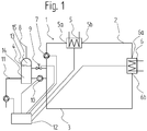
- Fig. 1 shows a heating device according to the invention for hot water production 1.
- a heating device 5 - with a heating device input 5a and a heater outlet 5b - heat is transferred from an external generator to a funded in the flow line 2 feed water flow.
- the heater outlet 5b opens into the flow line 2.
- the flow of feed water has a temperature of about 110 ° C and the pressure in the flow line is above the vapor pressure of the flow of feed water.
- a heat consumer 6 - with a heat consumer input 6a and a heat consumer output 6b - this heat withdraws again from the funded flow water flow of the flow line 2.
- Such heat consumers 6 are for example steam generators, district heating or drying plants.
- the heat consumer 6 is fed via the feed line 2 with the liquid flow of feed water via the heat consumer input 6a.
- a return water flow which arises after the removal of heat, is formed.
- This return water flow has a temperature of more than 105 ° C. and is conveyed in the direction of the heating device 5 in a return line 3, which is directly connected to the heat consumer outlet 6b, by means of a circulating pump 7.
- the return line 3 opens into the heater inlet 5a.
- a branch is provided in the return line 3, which has a pressure-maintaining pump 10 and opens into a compensation degassing device 4.
- the water in the equalization degasser 4 and the water in the supply line 2 and return line 3 are referred to as circulating water.
- the pressure holding pump 10 ensures that on the one hand an operating pressure in the waste heat plant for hot water production 1 is maintained and on the other hand, a constant inflow of circulating water, which is located in the equalizing degassing device 4, takes place in the return line 3.
- the operating pressure is at least above the vapor pressure of the feed water flow.
- Such waste heat plants for hot water production 1 are typically operated in a flow temperature range of 130 ° C to 230 ° C and an operating pressure of up to 45 bar, wherein the minimum pressure results from the vapor pressure of the flow temperature range.
- the return temperature range is dependent on the Flow temperature, in the range of 105 ° C to 200 ° C. These temperature and pressure ranges can deviate in certain operating states, such as during startup or shutdown of the hot water production heat recovery system 1.
- a pressure-maintaining valve 9 a subset of the return water flow of the return line 3 is continuously admitted into the compensation degassing device 4.
- the subset of the return water flow which is supplied to the equalization degassing device is at least 1 m 3 / h.
- An inlet 11 - for non-degassed water - allows new water to be supplied to the hot water production heat recovery system 1.
- This non-degassed water contains bound gases such as oxygen or carbon dioxide. These gases lead to corrosion in the waste heat plant for hot water production 1.
- the compensating degassing device 4 has a water collecting space 14 and a gas collecting space 15.
- a level 13 of the circulating water in the compensation degassing device 4 changes, depending on the operating state in which the hot water production heat recovery system 1 is currently located. The operating conditions change especially in non-continuous systems - for example in the steel and metal producing industry.
- a control device and / or Regeleinrichung 12 detects all measurement data from the different parts of the system and controls and / or controls the system according to the described method. Through an opening device 8, a gas / vapor mixture, which results from a degassing, drained.
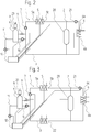
- Fig. 2 are in addition to those already in Fig. 1 treated system parts nor a buffer 20 with an additional circulation pump 21 is arranged.
- the buffer 20 allows temporary storage of excess heat and, if necessary, then deliver it to the heat consumer 6. This is particularly advantageous when the heat consumer 6 can not remove enough heat and when exceeding certain temperature ranges, a problem for the reliability - the heat recovery system for hot water production 1 - could occur.
- Another illustrated advantageous embodiment is the condenser 23. This condenser escapes escaping steam to water and returns it to the equalizing degassing device 4.
- Fig. 3 is, in addition to the in Fig. 2 shown system parts, an emergency cooler 22, which is arranged in the return line 3 shown.
- an emergency cooler can dissipate excess heat if the heat consumers 6 do not absorb heat or a problem occurs in the waste heat system for hot water production. This ensures that in the return line 3, the permissible temperatures are never exceeded.
Landscapes
- Chemical & Material Sciences (AREA)
- Chemical Kinetics & Catalysis (AREA)
- Engineering & Computer Science (AREA)
- Mechanical Engineering (AREA)
- General Engineering & Computer Science (AREA)
- Physics & Mathematics (AREA)
- Thermal Sciences (AREA)
- Life Sciences & Earth Sciences (AREA)
- Hydrology & Water Resources (AREA)
- Environmental & Geological Engineering (AREA)
- Water Supply & Treatment (AREA)
- Organic Chemistry (AREA)
- Physical Water Treatments (AREA)
- Waste-Gas Treatment And Other Accessory Devices For Furnaces (AREA)
Applications Claiming Priority (1)
| Application Number | Priority Date | Filing Date | Title |
|---|---|---|---|
| EP17194797.1A EP3467377A1 (fr) | 2017-10-04 | 2017-10-04 | Installation à flammes perdues pour la production d'eau chaude et procédé de fonctionnement d'une installation à flammes perdues pour la production d'eau chaude |
Publications (2)
| Publication Number | Publication Date |
|---|---|
| EP3467378A1 true EP3467378A1 (fr) | 2019-04-10 |
| EP3467378B1 EP3467378B1 (fr) | 2022-11-30 |
Family
ID=60021948
Family Applications (2)
| Application Number | Title | Priority Date | Filing Date |
|---|---|---|---|
| EP17194797.1A Withdrawn EP3467377A1 (fr) | 2017-10-04 | 2017-10-04 | Installation à flammes perdues pour la production d'eau chaude et procédé de fonctionnement d'une installation à flammes perdues pour la production d'eau chaude |
| EP18196814.0A Active EP3467378B1 (fr) | 2017-10-04 | 2018-09-26 | Installation à flammes perdues pour la production d'eau chaude et procédé de fonctionnement d'une installation à flammes perdues pour la production d'eau chaude |
Family Applications Before (1)
| Application Number | Title | Priority Date | Filing Date |
|---|---|---|---|
| EP17194797.1A Withdrawn EP3467377A1 (fr) | 2017-10-04 | 2017-10-04 | Installation à flammes perdues pour la production d'eau chaude et procédé de fonctionnement d'une installation à flammes perdues pour la production d'eau chaude |
Country Status (1)
| Country | Link |
|---|---|
| EP (2) | EP3467377A1 (fr) |
Citations (10)
| Publication number | Priority date | Publication date | Assignee | Title |
|---|---|---|---|---|
| US455906A (en) | 1891-07-14 | Furniture-caster | ||
| US509039A (en) | 1893-11-21 | Bolt-threader | ||
| DE346748C (de) | 1922-01-06 | Helmut Schulte Steinberg Dipl | Schleudermuehle fuer die Lehmaufbereitung | |
| DE511005C (de) * | 1928-01-27 | 1930-10-25 | Karl Morawe Dipl Ing | Einrichtung zum Entgasen von Fluessigkeiten |
| DE2821397A1 (de) | 1978-04-25 | 1979-11-08 | Bbc Brown Boveri & Cie | Kombiniertes gas/dampfturbinenkraftwerk, vorgesehen zum betrieb mit brennstoffen von verschieden hohem schwefelgehalt |
| FR2524547A1 (fr) * | 1982-03-31 | 1983-10-07 | Sulzer Ag | Generateur de vapeur a gaz perdu et a degazeur |
| US4555906A (en) * | 1984-10-25 | 1985-12-03 | Westinghouse Electric Corp. | Deaerator pressure control system for a combined cycle steam generator power plant |
| WO1996036792A1 (fr) | 1995-05-15 | 1996-11-21 | Siemens Aktiengesellschaft | Procede et dispositif permettant de degazer un condensat |
| US5904039A (en) * | 1995-05-15 | 1999-05-18 | Siemens Aktiengesellschaft | Method and configuration for deaerating a condensate |
| DE102009004622A1 (de) * | 2009-01-01 | 2010-07-08 | Fritz Curtius | Dampferzeuger mit einem Behälter für Speisewasser |
Family Cites Families (1)
| Publication number | Priority date | Publication date | Assignee | Title |
|---|---|---|---|---|
| DE446748C (de) | 1925-04-29 | 1927-07-09 | Fritz Stein | Schnittandeuter fuer Papierscheren mit Kreismesser |
-
2017
- 2017-10-04 EP EP17194797.1A patent/EP3467377A1/fr not_active Withdrawn
-
2018
- 2018-09-26 EP EP18196814.0A patent/EP3467378B1/fr active Active
Patent Citations (10)
| Publication number | Priority date | Publication date | Assignee | Title |
|---|---|---|---|---|
| US455906A (en) | 1891-07-14 | Furniture-caster | ||
| US509039A (en) | 1893-11-21 | Bolt-threader | ||
| DE346748C (de) | 1922-01-06 | Helmut Schulte Steinberg Dipl | Schleudermuehle fuer die Lehmaufbereitung | |
| DE511005C (de) * | 1928-01-27 | 1930-10-25 | Karl Morawe Dipl Ing | Einrichtung zum Entgasen von Fluessigkeiten |
| DE2821397A1 (de) | 1978-04-25 | 1979-11-08 | Bbc Brown Boveri & Cie | Kombiniertes gas/dampfturbinenkraftwerk, vorgesehen zum betrieb mit brennstoffen von verschieden hohem schwefelgehalt |
| FR2524547A1 (fr) * | 1982-03-31 | 1983-10-07 | Sulzer Ag | Generateur de vapeur a gaz perdu et a degazeur |
| US4555906A (en) * | 1984-10-25 | 1985-12-03 | Westinghouse Electric Corp. | Deaerator pressure control system for a combined cycle steam generator power plant |
| WO1996036792A1 (fr) | 1995-05-15 | 1996-11-21 | Siemens Aktiengesellschaft | Procede et dispositif permettant de degazer un condensat |
| US5904039A (en) * | 1995-05-15 | 1999-05-18 | Siemens Aktiengesellschaft | Method and configuration for deaerating a condensate |
| DE102009004622A1 (de) * | 2009-01-01 | 2010-07-08 | Fritz Curtius | Dampferzeuger mit einem Behälter für Speisewasser |
Also Published As
| Publication number | Publication date |
|---|---|
| EP3467377A1 (fr) | 2019-04-10 |
| EP3467378B1 (fr) | 2022-11-30 |
Similar Documents
| Publication | Publication Date | Title |
|---|---|---|
| EP2812542B1 (fr) | Centrale d'accumulation d'énergie et procédé de fonctionnement d'une telle centrale | |
| DE68926220T2 (de) | Verfahren und Vorrichtung zur Dampfkrafterzeugung | |
| DE2311066A1 (de) | Dampferzeuger fuer ungefeuerte kraftanlage | |
| EP2095370A1 (fr) | Installation technique nucléaire et procédé d'utilisation d'une installation technique nucléaire | |
| EP2986910B1 (fr) | Système et procédé de préchauffage d'eau d'alimentation dans des centrales électriques à vapeur avec découplage de la vapeur de processus | |
| DE102012010382A1 (de) | Verfahren und Anordnung zur Rückgewinnung von Wärmeenergie bei der Wärmebehandlung von kaltgewalztem Stahlband in einem Haubenglühofen | |
| DE102008013933A1 (de) | Verfahren und Vorrichtung zum Abtrennen eines Neutronenabsorbers von einem Kühlmittel eines Kühlkreislaufes | |
| DE102016214447B4 (de) | Kraftwerk mit Phasenwechselmaterial-Wärmespeicher und Verfahren zum Betreiben eines Kraftwerks mit Phasenwechselmaterial-Wärmespeicher | |
| EP3467378B1 (fr) | Installation à flammes perdues pour la production d'eau chaude et procédé de fonctionnement d'une installation à flammes perdues pour la production d'eau chaude | |
| CH622332A5 (fr) | ||
| EP2619334B1 (fr) | Procédé d'exploitation pour l'utilisation de la chaleur thermique perdue pour une installation de l'industrie des matières premières | |
| EP0476449A2 (fr) | Procédé et dispositif pour le séchage du gaz naturel et pour le recyclage du solvant de l'eau utilisé en cela | |
| EP3134694B1 (fr) | Procédé et installation destinés à l'utilisation de la chaleur dissipée des gaz d'échappement dans la production de vapeur | |
| WO2013170916A1 (fr) | Procédé et dispositif d'épuration d'eaux usées industrielles | |
| EP2964910B1 (fr) | Procédé destiné au fonctionnement flexible d'une centrale électrique | |
| AT510688B1 (de) | Betriebsverfahren für eine anlage der grundstoffindustrie | |
| DE1288614B (de) | Verfahren und Vorrichtung zum Abbau von Dampfspitzen aus Prozessabfallwaermeverwertern mit variabler Dampferzeugung | |
| EP1101226A2 (fr) | Procede et dispositif pour separer un absorbeur de neutrons, contenu dans un caloporteur | |
| EP1777709B1 (fr) | Procédé de réglage de la pression du fluide de refroidissement dans le circuit primaire d'une centrale nucléaire et centrale nucléaire équipée d'un dispositif apte à mettre en oeuvre ce procédé | |
| DE1089396B (de) | Dampfkraftanlage mit Zwangstromkessel und Zwischenueberhitzung | |
| DE102013205053B4 (de) | Verfahren zum Betrieb eines einen Wasser-Dampf-Kreislauf aufweisenden Kraftwerks | |
| WO2019238905A1 (fr) | Procédé de fonctionnement et unité de commande pour un système de cogénération et système de cogénération | |
| AT234730B (de) | Verfahren und Vorrichtung zum Abbau von Dampfspitzen aus Prozeßabfallwärmeverwertern mit variabler Dampferzeugung | |
| AT150129B (de) | Verfahren zur Erzeugung von Dampf. | |
| DE102019217996A1 (de) | Vorrichtung und Verfahren zur Ausspeicherung eines thermischen Energiespeichers, insbesondere eines Schüttgutspeichers |
Legal Events
| Date | Code | Title | Description |
|---|---|---|---|
| PUAI | Public reference made under article 153(3) epc to a published international application that has entered the european phase |
Free format text: ORIGINAL CODE: 0009012 |
|
| STAA | Information on the status of an ep patent application or granted ep patent |
Free format text: STATUS: THE APPLICATION HAS BEEN PUBLISHED |
|
| AK | Designated contracting states |
Kind code of ref document: A1 Designated state(s): AL AT BE BG CH CY CZ DE DK EE ES FI FR GB GR HR HU IE IS IT LI LT LU LV MC MK MT NL NO PL PT RO RS SE SI SK SM TR |
|
| AX | Request for extension of the european patent |
Extension state: BA ME |
|
| STAA | Information on the status of an ep patent application or granted ep patent |
Free format text: STATUS: REQUEST FOR EXAMINATION WAS MADE |
|
| 17P | Request for examination filed |
Effective date: 20191010 |
|
| RBV | Designated contracting states (corrected) |
Designated state(s): AL AT BE BG CH CY CZ DE DK EE ES FI FR GB GR HR HU IE IS IT LI LT LU LV MC MK MT NL NO PL PT RO RS SE SI SK SM TR |
|
| GRAP | Despatch of communication of intention to grant a patent |
Free format text: ORIGINAL CODE: EPIDOSNIGR1 |
|
| STAA | Information on the status of an ep patent application or granted ep patent |
Free format text: STATUS: GRANT OF PATENT IS INTENDED |
|
| INTG | Intention to grant announced |
Effective date: 20220719 |
|
| GRAS | Grant fee paid |
Free format text: ORIGINAL CODE: EPIDOSNIGR3 |
|
| GRAA | (expected) grant |
Free format text: ORIGINAL CODE: 0009210 |
|
| STAA | Information on the status of an ep patent application or granted ep patent |
Free format text: STATUS: THE PATENT HAS BEEN GRANTED |
|
| AK | Designated contracting states |
Kind code of ref document: B1 Designated state(s): AL AT BE BG CH CY CZ DE DK EE ES FI FR GB GR HR HU IE IS IT LI LT LU LV MC MK MT NL NO PL PT RO RS SE SI SK SM TR |
|
| REG | Reference to a national code |
Ref country code: CH Ref legal event code: EP Ref country code: GB Ref legal event code: FG4D Free format text: NOT ENGLISH |
|
| REG | Reference to a national code |
Ref country code: AT Ref legal event code: REF Ref document number: 1534939 Country of ref document: AT Kind code of ref document: T Effective date: 20221215 Ref country code: DE Ref legal event code: R096 Ref document number: 502018011135 Country of ref document: DE |
|
| REG | Reference to a national code |
Ref country code: IE Ref legal event code: FG4D Free format text: LANGUAGE OF EP DOCUMENT: GERMAN |
|
| REG | Reference to a national code |
Ref country code: LT Ref legal event code: MG9D |
|
| REG | Reference to a national code |
Ref country code: NL Ref legal event code: MP Effective date: 20221130 |
|
| PG25 | Lapsed in a contracting state [announced via postgrant information from national office to epo] |
Ref country code: SE Free format text: LAPSE BECAUSE OF FAILURE TO SUBMIT A TRANSLATION OF THE DESCRIPTION OR TO PAY THE FEE WITHIN THE PRESCRIBED TIME-LIMIT Effective date: 20221130 Ref country code: PT Free format text: LAPSE BECAUSE OF FAILURE TO SUBMIT A TRANSLATION OF THE DESCRIPTION OR TO PAY THE FEE WITHIN THE PRESCRIBED TIME-LIMIT Effective date: 20230331 Ref country code: NO Free format text: LAPSE BECAUSE OF FAILURE TO SUBMIT A TRANSLATION OF THE DESCRIPTION OR TO PAY THE FEE WITHIN THE PRESCRIBED TIME-LIMIT Effective date: 20230228 Ref country code: LT Free format text: LAPSE BECAUSE OF FAILURE TO SUBMIT A TRANSLATION OF THE DESCRIPTION OR TO PAY THE FEE WITHIN THE PRESCRIBED TIME-LIMIT Effective date: 20221130 Ref country code: FI Free format text: LAPSE BECAUSE OF FAILURE TO SUBMIT A TRANSLATION OF THE DESCRIPTION OR TO PAY THE FEE WITHIN THE PRESCRIBED TIME-LIMIT Effective date: 20221130 Ref country code: ES Free format text: LAPSE BECAUSE OF FAILURE TO SUBMIT A TRANSLATION OF THE DESCRIPTION OR TO PAY THE FEE WITHIN THE PRESCRIBED TIME-LIMIT Effective date: 20221130 |
|
| PG25 | Lapsed in a contracting state [announced via postgrant information from national office to epo] |
Ref country code: RS Free format text: LAPSE BECAUSE OF FAILURE TO SUBMIT A TRANSLATION OF THE DESCRIPTION OR TO PAY THE FEE WITHIN THE PRESCRIBED TIME-LIMIT Effective date: 20221130 Ref country code: PL Free format text: LAPSE BECAUSE OF FAILURE TO SUBMIT A TRANSLATION OF THE DESCRIPTION OR TO PAY THE FEE WITHIN THE PRESCRIBED TIME-LIMIT Effective date: 20221130 Ref country code: LV Free format text: LAPSE BECAUSE OF FAILURE TO SUBMIT A TRANSLATION OF THE DESCRIPTION OR TO PAY THE FEE WITHIN THE PRESCRIBED TIME-LIMIT Effective date: 20221130 Ref country code: IS Free format text: LAPSE BECAUSE OF FAILURE TO SUBMIT A TRANSLATION OF THE DESCRIPTION OR TO PAY THE FEE WITHIN THE PRESCRIBED TIME-LIMIT Effective date: 20230330 Ref country code: HR Free format text: LAPSE BECAUSE OF FAILURE TO SUBMIT A TRANSLATION OF THE DESCRIPTION OR TO PAY THE FEE WITHIN THE PRESCRIBED TIME-LIMIT Effective date: 20221130 Ref country code: GR Free format text: LAPSE BECAUSE OF FAILURE TO SUBMIT A TRANSLATION OF THE DESCRIPTION OR TO PAY THE FEE WITHIN THE PRESCRIBED TIME-LIMIT Effective date: 20230301 |
|
| PG25 | Lapsed in a contracting state [announced via postgrant information from national office to epo] |
Ref country code: NL Free format text: LAPSE BECAUSE OF FAILURE TO SUBMIT A TRANSLATION OF THE DESCRIPTION OR TO PAY THE FEE WITHIN THE PRESCRIBED TIME-LIMIT Effective date: 20221130 |
|
| PG25 | Lapsed in a contracting state [announced via postgrant information from national office to epo] |
Ref country code: SM Free format text: LAPSE BECAUSE OF FAILURE TO SUBMIT A TRANSLATION OF THE DESCRIPTION OR TO PAY THE FEE WITHIN THE PRESCRIBED TIME-LIMIT Effective date: 20221130 Ref country code: RO Free format text: LAPSE BECAUSE OF FAILURE TO SUBMIT A TRANSLATION OF THE DESCRIPTION OR TO PAY THE FEE WITHIN THE PRESCRIBED TIME-LIMIT Effective date: 20221130 Ref country code: EE Free format text: LAPSE BECAUSE OF FAILURE TO SUBMIT A TRANSLATION OF THE DESCRIPTION OR TO PAY THE FEE WITHIN THE PRESCRIBED TIME-LIMIT Effective date: 20221130 Ref country code: DK Free format text: LAPSE BECAUSE OF FAILURE TO SUBMIT A TRANSLATION OF THE DESCRIPTION OR TO PAY THE FEE WITHIN THE PRESCRIBED TIME-LIMIT Effective date: 20221130 Ref country code: CZ Free format text: LAPSE BECAUSE OF FAILURE TO SUBMIT A TRANSLATION OF THE DESCRIPTION OR TO PAY THE FEE WITHIN THE PRESCRIBED TIME-LIMIT Effective date: 20221130 |
|
| PG25 | Lapsed in a contracting state [announced via postgrant information from national office to epo] |
Ref country code: SK Free format text: LAPSE BECAUSE OF FAILURE TO SUBMIT A TRANSLATION OF THE DESCRIPTION OR TO PAY THE FEE WITHIN THE PRESCRIBED TIME-LIMIT Effective date: 20221130 Ref country code: AL Free format text: LAPSE BECAUSE OF FAILURE TO SUBMIT A TRANSLATION OF THE DESCRIPTION OR TO PAY THE FEE WITHIN THE PRESCRIBED TIME-LIMIT Effective date: 20221130 |
|
| REG | Reference to a national code |
Ref country code: DE Ref legal event code: R097 Ref document number: 502018011135 Country of ref document: DE |
|
| PLBE | No opposition filed within time limit |
Free format text: ORIGINAL CODE: 0009261 |
|
| STAA | Information on the status of an ep patent application or granted ep patent |
Free format text: STATUS: NO OPPOSITION FILED WITHIN TIME LIMIT |
|
| PGFP | Annual fee paid to national office [announced via postgrant information from national office to epo] |
Ref country code: AT Payment date: 20230921 Year of fee payment: 6 |
|
| 26N | No opposition filed |
Effective date: 20230831 |
|
| PG25 | Lapsed in a contracting state [announced via postgrant information from national office to epo] |
Ref country code: SI Free format text: LAPSE BECAUSE OF FAILURE TO SUBMIT A TRANSLATION OF THE DESCRIPTION OR TO PAY THE FEE WITHIN THE PRESCRIBED TIME-LIMIT Effective date: 20221130 |
|
| PGFP | Annual fee paid to national office [announced via postgrant information from national office to epo] |
Ref country code: DE Payment date: 20230920 Year of fee payment: 6 |
|
| PGFP | Annual fee paid to national office [announced via postgrant information from national office to epo] |
Ref country code: IT Payment date: 20230927 Year of fee payment: 6 |
|
| REG | Reference to a national code |
Ref country code: CH Ref legal event code: PL |
|
| PG25 | Lapsed in a contracting state [announced via postgrant information from national office to epo] |
Ref country code: LU Free format text: LAPSE BECAUSE OF NON-PAYMENT OF DUE FEES Effective date: 20230926 |
|
| REG | Reference to a national code |
Ref country code: BE Ref legal event code: MM Effective date: 20230930 |
|
| GBPC | Gb: european patent ceased through non-payment of renewal fee |
Effective date: 20230926 |
|
| PG25 | Lapsed in a contracting state [announced via postgrant information from national office to epo] |
Ref country code: LU Free format text: LAPSE BECAUSE OF NON-PAYMENT OF DUE FEES Effective date: 20230926 Ref country code: MC Free format text: LAPSE BECAUSE OF FAILURE TO SUBMIT A TRANSLATION OF THE DESCRIPTION OR TO PAY THE FEE WITHIN THE PRESCRIBED TIME-LIMIT Effective date: 20221130 |
|
| REG | Reference to a national code |
Ref country code: IE Ref legal event code: MM4A |
|
| PG25 | Lapsed in a contracting state [announced via postgrant information from national office to epo] |
Ref country code: IE Free format text: LAPSE BECAUSE OF NON-PAYMENT OF DUE FEES Effective date: 20230926 |
|
| PG25 | Lapsed in a contracting state [announced via postgrant information from national office to epo] |
Ref country code: GB Free format text: LAPSE BECAUSE OF NON-PAYMENT OF DUE FEES Effective date: 20230926 |
|
| PG25 | Lapsed in a contracting state [announced via postgrant information from national office to epo] |
Ref country code: CH Free format text: LAPSE BECAUSE OF NON-PAYMENT OF DUE FEES Effective date: 20230930 |
|
| PG25 | Lapsed in a contracting state [announced via postgrant information from national office to epo] |
Ref country code: IE Free format text: LAPSE BECAUSE OF NON-PAYMENT OF DUE FEES Effective date: 20230926 Ref country code: GB Free format text: LAPSE BECAUSE OF NON-PAYMENT OF DUE FEES Effective date: 20230926 Ref country code: FR Free format text: LAPSE BECAUSE OF NON-PAYMENT OF DUE FEES Effective date: 20230930 Ref country code: CH Free format text: LAPSE BECAUSE OF NON-PAYMENT OF DUE FEES Effective date: 20230930 |
|
| PG25 | Lapsed in a contracting state [announced via postgrant information from national office to epo] |
Ref country code: BE Free format text: LAPSE BECAUSE OF NON-PAYMENT OF DUE FEES Effective date: 20230930 |