EP3467351A1 - Cap with helical lsd clutch - Google Patents
Cap with helical lsd clutch Download PDFInfo
- Publication number
- EP3467351A1 EP3467351A1 EP16904010.2A EP16904010A EP3467351A1 EP 3467351 A1 EP3467351 A1 EP 3467351A1 EP 16904010 A EP16904010 A EP 16904010A EP 3467351 A1 EP3467351 A1 EP 3467351A1
- Authority
- EP
- European Patent Office
- Prior art keywords
- face
- portions
- clutch
- cap
- casing
- Prior art date
- Legal status (The legal status is an assumption and is not a legal conclusion. Google has not performed a legal analysis and makes no representation as to the accuracy of the status listed.)
- Granted
Links
- 238000004891 communication Methods 0.000 claims abstract description 4
- 230000000149 penetrating effect Effects 0.000 claims description 2
- 230000004323 axial length Effects 0.000 claims 1
- 238000005242 forging Methods 0.000 description 4
- 238000003754 machining Methods 0.000 description 3
- 239000000463 material Substances 0.000 description 2
- 208000019901 Anxiety disease Diseases 0.000 description 1
- 230000036506 anxiety Effects 0.000 description 1
- 238000005452 bending Methods 0.000 description 1
- 230000005540 biological transmission Effects 0.000 description 1
- 230000015572 biosynthetic process Effects 0.000 description 1
- 230000006835 compression Effects 0.000 description 1
- 238000007906 compression Methods 0.000 description 1
- 230000008878 coupling Effects 0.000 description 1
- 238000010168 coupling process Methods 0.000 description 1
- 238000005859 coupling reaction Methods 0.000 description 1
- 238000012986 modification Methods 0.000 description 1
- 230000004048 modification Effects 0.000 description 1
- 238000005549 size reduction Methods 0.000 description 1
- 239000007779 soft material Substances 0.000 description 1
Images


Classifications
-
- F—MECHANICAL ENGINEERING; LIGHTING; HEATING; WEAPONS; BLASTING
- F16—ENGINEERING ELEMENTS AND UNITS; GENERAL MEASURES FOR PRODUCING AND MAINTAINING EFFECTIVE FUNCTIONING OF MACHINES OR INSTALLATIONS; THERMAL INSULATION IN GENERAL
- F16H—GEARING
- F16H48/00—Differential gearings
- F16H48/20—Arrangements for suppressing or influencing the differential action, e.g. locking devices
- F16H48/24—Arrangements for suppressing or influencing the differential action, e.g. locking devices using positive clutches or brakes
-
- F—MECHANICAL ENGINEERING; LIGHTING; HEATING; WEAPONS; BLASTING
- F16—ENGINEERING ELEMENTS AND UNITS; GENERAL MEASURES FOR PRODUCING AND MAINTAINING EFFECTIVE FUNCTIONING OF MACHINES OR INSTALLATIONS; THERMAL INSULATION IN GENERAL
- F16H—GEARING
- F16H48/00—Differential gearings
- F16H48/06—Differential gearings with gears having orbital motion
- F16H48/10—Differential gearings with gears having orbital motion with orbital spur gears
-
- F—MECHANICAL ENGINEERING; LIGHTING; HEATING; WEAPONS; BLASTING
- F16—ENGINEERING ELEMENTS AND UNITS; GENERAL MEASURES FOR PRODUCING AND MAINTAINING EFFECTIVE FUNCTIONING OF MACHINES OR INSTALLATIONS; THERMAL INSULATION IN GENERAL
- F16H—GEARING
- F16H48/00—Differential gearings
- F16H48/20—Arrangements for suppressing or influencing the differential action, e.g. locking devices
- F16H48/28—Arrangements for suppressing or influencing the differential action, e.g. locking devices using self-locking gears or self-braking gears
- F16H48/285—Arrangements for suppressing or influencing the differential action, e.g. locking devices using self-locking gears or self-braking gears with self-braking intermeshing gears having parallel axes and having worms or helical teeth
-
- F—MECHANICAL ENGINEERING; LIGHTING; HEATING; WEAPONS; BLASTING
- F16—ENGINEERING ELEMENTS AND UNITS; GENERAL MEASURES FOR PRODUCING AND MAINTAINING EFFECTIVE FUNCTIONING OF MACHINES OR INSTALLATIONS; THERMAL INSULATION IN GENERAL
- F16H—GEARING
- F16H48/00—Differential gearings
- F16H48/20—Arrangements for suppressing or influencing the differential action, e.g. locking devices
- F16H48/30—Arrangements for suppressing or influencing the differential action, e.g. locking devices using externally-actuatable means
- F16H48/34—Arrangements for suppressing or influencing the differential action, e.g. locking devices using externally-actuatable means using electromagnetic or electric actuators
-
- F—MECHANICAL ENGINEERING; LIGHTING; HEATING; WEAPONS; BLASTING
- F16—ENGINEERING ELEMENTS AND UNITS; GENERAL MEASURES FOR PRODUCING AND MAINTAINING EFFECTIVE FUNCTIONING OF MACHINES OR INSTALLATIONS; THERMAL INSULATION IN GENERAL
- F16H—GEARING
- F16H48/00—Differential gearings
- F16H48/06—Differential gearings with gears having orbital motion
- F16H48/10—Differential gearings with gears having orbital motion with orbital spur gears
- F16H2048/106—Differential gearings with gears having orbital motion with orbital spur gears characterised by two sun gears
-
- F—MECHANICAL ENGINEERING; LIGHTING; HEATING; WEAPONS; BLASTING
- F16—ENGINEERING ELEMENTS AND UNITS; GENERAL MEASURES FOR PRODUCING AND MAINTAINING EFFECTIVE FUNCTIONING OF MACHINES OR INSTALLATIONS; THERMAL INSULATION IN GENERAL
- F16H—GEARING
- F16H48/00—Differential gearings
- F16H48/38—Constructional details
- F16H48/42—Constructional details characterised by features of the input shafts, e.g. mounting of drive gears thereon
- F16H2048/423—Constructional details characterised by features of the input shafts, e.g. mounting of drive gears thereon characterised by bearing arrangement
-
- F—MECHANICAL ENGINEERING; LIGHTING; HEATING; WEAPONS; BLASTING
- F16—ENGINEERING ELEMENTS AND UNITS; GENERAL MEASURES FOR PRODUCING AND MAINTAINING EFFECTIVE FUNCTIONING OF MACHINES OR INSTALLATIONS; THERMAL INSULATION IN GENERAL
- F16H—GEARING
- F16H48/00—Differential gearings
- F16H48/20—Arrangements for suppressing or influencing the differential action, e.g. locking devices
- F16H48/30—Arrangements for suppressing or influencing the differential action, e.g. locking devices using externally-actuatable means
Definitions
- the disclosure herein relates to a cap with a clutch preferably applicable to a helical limited-slip differential (LSD) for a vehicle and in particular to a cap that in combination with its casing constitutes a clutch for locking up differential motion of a helical LSD.
- LSD helical limited-slip differential
- a helical LSD As a differential that automatically limits differential motion, a helical LSD has been often used.
- the engagement force acts not only in the radial direction but also in the axial direction. This thrust force presses the respective gears onto the casing to limit rotation thereof, so that the helical LSD torque-sensitively limits the differential motion of itself. Caps covering both ends thereof must bear the thrust force.
- the PTL 1 discloses a related art.
- a cap for use with a casing of a helical LSD rotatable about an axis to lock up differential motion, is provided with: a clutch member combinable with any of sun gears of the helical LSD and including clutch teeth; a clutch ring including a ring portion including clutch teeth so as to mesh with the clutch member and one or more tab portions being unitary with and projecting radially outward from the ring portion; a cap main body fixed on an axial end of the casing, the cap main body having a first face in contact with the casing and a second face axially opposed to the first face; a receding portion of the cap main body receding from the first face toward the second face and being so dimensioned as to receive and allow the clutch ring to be axially movable, the receding portion including one or more dock portions respectively receiving the tab portions; an opening opened on the second face and in spatial communication with any of the dog portions to allow access to the tab portions; side faces of the tab portions, each of the side faces inclining
- an axis means a rotational axis of a limited-slip differential (LSD) unless otherwise described. Further, while the right and the left may be sometimes discriminated in the following description, this is merely for the convenience of explanation and therefore does not limit embodiments.
- LSD limited-slip differential
- a helical LSD 1 is a kind of differential gear.
- the helical LSD 1 is rotatable about an axis C, a cap 3 is combined with an end thereof and an end cap 5 is combined with another end.
- the caps 3, 5 bear thrust force acting on the planetary gears 17, 21 and the sun gears 23, 25 and meanwhile the cap 3 contains a mechanism for locking differential motion between the sun gears 23, 25.
- An actuator 7 is a mechanism for driving the locking mechanism.
- the helical LSD 1 is in general comprised of a generally cylindrical casing 11, a flange 13 fixedly combined therewith or forming a unitary body therewith, the planetary gears 17, 21 and the sun gears 23, 25 both housed in the casing 11.
- the flange 13 projects radially outward from the casing 11 and receives torque via a ring gear combined therewith for example from an engine/motor, thereby the casing 11 rotates about the axis C.
- the casing 11 is provided with a plurality of long bores 15 and a plurality of short bores 19 both running in parallel with the axis C.
- the long bores 15 can be opened on both ends of the casing 11 but the short bores 19 start from one end adjacent to the end cap 5 and terminate at an end wall 27.
- Each long bore 15 houses a long pinion 17 of the planetary gears and each short bore 19 houses a short pinion 21 likewise.
- the sun gears 23, 25 are housed around the center of the casing 11.
- the long pinions 17 and the short pinions 21 are in mesh with each other and are further in mesh with the sun gears 23, 25.
- the torque is thereby transmitted from the casing 11 through the planetary gears 17, 21 to the sun gears 23, 25 and as well gearing among them enables differential motion between the sun gears 23, 25.
- the pinions 17, 21 and the sun gears 23, 25 are all helical gears.
- thrust force acts thereon and are born by the caps 3, 5 fixed to both ends of the casing 11 and the end wall 27 of the casing 11. Further, friction arising from the thrust force limits rotation of the pinions 17, 21, so that the helical LSD 1 torque-sensitively limits differential motion.
- the cap 3 is in general comprised of a clutch member 31, a clutch ring 33 and a cap main body 35, and the combination of the clutch member 31 and the clutch ring 33 constitutes a clutch.
- the clutch member 31 is, by means of splines for example, combined with one of the sun gears 23 and the clutch ring 33, when coupled therewith, locks the sun gear 23 relative to the cap 3, thereby locking up differential motion of the helical LSD 1.
- the clutch ring 33 is comprised of a ring portion 41, the totality of which is generally ring-shaped, and a plurality of tab portions 43 projecting radially outward from the ring portion 41.
- the tab portions 43 are arranged in a rotationally symmetric fashion about the axis C and the number thereof is four for instance as shown in the drawings.
- the arrangement and the number of the tab portions 43 may be set as the same as those of the long pinions 17.
- the totality of the clutch ring 33 may be produced by forging and machining for example.
- the whole of the cap main body 35 is shaped like a round pan, which has an inner face (first face) 45 in contact with the casing 11 and an outer face (second face) 47 axially opposed to the inner face, and around the center thereof formed is a receding portion 49 receding from the first face 45 toward the second face 47 so as to receive the clutch ring 33.
- the recess portion 49 is generally round according to the clutch ring 33 but has a plurality of dock portions 51 respectively receiving the tab portions 43.
- the clutch ring 33 is received in the recess portion 49 and is movable therein along the axis C and yet movable slightly in the circumferential direction.
- the cap main body 35 is provided with one or more openings 37 opened on the second face 47.
- the openings 37 are respectively spatially in communication with the dock portions 51 to allow access from the exterior to the tab portions 43 in the dock portions 51.
- the openings 37 may be opened toward all the dock portions 51, or alternatively may be limited to some dock portions 51.
- the plural openings 37 are preferably rotationally symmetric about the axis C.
- a pressure plate 39 to be driven by the actuator 7 in the direction of the axis C intrudes through the openings 37 into the dock portions 51 and is there combined with the tab portions 43, so that the actuator 7 is enabled to drive the clutch ring 33.
- both side faces 55 of the respective tab portions 43 which are somehow directed in the circumferential directions, are not perpendicular to the circumferential directions but inclined toward the cap main body 35.
- inner faces 57 of the respective dock portions 51 are not perpendicular to the circumferential directions but inclined toward the first face 45.
- the combination of these oblique side faces 55 and inner faces 57 when getting contact with each other, constitutes a cam for pressing the clutch ring 33 in the direction of the axis C toward the clutch member 31.
- the tab 43 may be formed sufficiently thick in the direction of the axis C so as to prevent buckling caused by the load from the pressure force, and the side faces 55 of the tab portions 43 may be formed longer in length in the axial direction than the inner faces 57 of the dock portions 51.
- each of the base portions 53 has a shape capable of having axially close contact with the casing 11.
- the base portions 53 may be provided with through-holes 65 axially penetrating the base portions 53 and are fixed with the casing 11 by means of a plurality of bolts 69 (see FIG. 1 ). While the base portions 53 bear counter-force by the cam, as they are in continuity in the circumferential direction and as they are to be integrated with the casing, the base portions 53 effectively prevent the cap main body 35 from deforming or being damaged.
- the casing 11 is provided with tap holes 67 corresponding to the through-holes 65 of the cap main body 35, and the long bores 15 respectively housing the long pinions 17 are located between the tap holes 67.
- the locations of the long bores 15 and the long pinions 17 are corresponding to the locations of the tab portions 43 and the dock portions 51 in the circumferential direction.
- the locations of the short bores 19 and the short pinions 21 necessarily overlap the locations of the tap holes 67 and the through-holes 65 in the circumferential direction, as being understood from FIG. 1
- the end wall 27 is sufficiently apart from the contact face on the cap main body 35 so that the tap holes 67 do not interfere with the short bores 19. It is unnecessary to dispose the tap holes 67 radially outward and therefore the present embodiment is advantageous in size reduction of the helical LSD 1.
- the clutch member 31 is, at its internal periphery for instance, combinable with the sun gear 23.
- This coupling may be established by splines for example, or alternatively they may be a unitary body.
- the clutch member 31, around its outer periphery, may overlap with the long pinions 17 and may thereby bear the thrust force acting on the long pinions 17.
- the clutch member 31 is elongated along the bore portion of the sun gear 23 to pass through the internal periphery of the clutch ring 33, thereby getting in contact with the cap main body 35.
- the clutch member 31 may be directly in contact with the cap main body 35 or alternatively may have any thrust bearing or washer or such interposed therebetween. Specifically, the cap main body 35 can bear the thrust force acting on the long pinions 17 via the clutch member 31.
- the clutch member 31 and the clutch ring 33 are provided with mutually engageable clutch teeth 61, 63, thereby constituting the clutch.
- a return spring may be interposed between the clutch member 31 and the clutch ring 33, or between the clutch ring 33 and the casing 11, to urge the clutch teeth 61, 63 to be disengaged.
- the actuator 7 is, as described already, a means for driving the locking mechanism and is formed of an electromagnet for example.
- any hydraulic device, any pneumatic device, a combination of a motor and a cam device or any proper means that produces driving force in the axial direction is applicable to the actuator 7.
- the actuator 7 may be fixed to a stationary member or slidably fit on the bore portion of the cap main body 35 and be anti-rotated.
- the clutch ring 33 when the actuator 7 does not exert driving force on the clutch ring 33, the clutch ring 33 is disengaged from the clutch member 31 and differential motion between the sun gears 23, 25 is enabled. As the actuator 7 presses, via the pressure plate 39, the clutch ring 33 in the direction of the axis C, the clutch teeth 61, 63 get mutually engaged and then the clutch ring 33 is connected to the clutch member 31, thereby locking the differential motion.
- the actuator 7 can use this assisting force, the actuator 7 can, without keeping exerting great driving force, preserve the connection between the clutch ring 33 and the clutch member 31.
- the cam mechanism As the cam mechanism is used to assist the actuator 7, it becomes unnecessary to use a large-sized actuator and the cam mechanism is by itself compact in the axial direction. Therefore the cap 3 capable of locking the differential motion is notably compact.
- both the clutch member 31 and the clutch ring 33 do not have a structure bulging out in the axial direction, they can be readily produced by forging and machining. Because forging is applicable, any higher-strength material is available and therefore it assures high durability.
- cap main body 35 also has any structure equivalent to so-called undercuts, it can be produced by forging and machining. It is unnecessary to use any soft material that enables formation of undercuts, and instead any higher-strength material is available. This leads to high durability.
- a cap applicable to a helical LSD which has a function of locking differential motion but is compact and highly durable, is provided.
Landscapes
- Engineering & Computer Science (AREA)
- General Engineering & Computer Science (AREA)
- Mechanical Engineering (AREA)
- Physics & Mathematics (AREA)
- Electromagnetism (AREA)
- Retarders (AREA)
Abstract
Description
- The disclosure herein relates to a cap with a clutch preferably applicable to a helical limited-slip differential (LSD) for a vehicle and in particular to a cap that in combination with its casing constitutes a clutch for locking up differential motion of a helical LSD.
- To transmit torque from a shaft to right and left axles, it is required to use a differential gear in order to allow differential motion between these axles. On the other hand, when one of right and left driving wheels loses its traction, in order to secure torque transmission to the other driving wheel, the differential motion should be limited.
- As a differential that automatically limits differential motion, a helical LSD has been often used. In a helical LSD, as both planetary gears and sun gears are helical gears, the engagement force acts not only in the radial direction but also in the axial direction. This thrust force presses the respective gears onto the casing to limit rotation thereof, so that the helical LSD torque-sensitively limits the differential motion of itself. Caps covering both ends thereof must bear the thrust force.
- In addition to the automatic differential limitation in the helical LSD, it may be desired to enable external control for limiting or locking up the differential motion. The caps, as they must bear the thrust force as described above, in general get in direct contact with the planetary gears and the sun gears. Thus a structure for lock-up should be additionally placed axially outside the cap or any structure equivalent thereto.
- The PTL 1 discloses a related art.
- PTL 1: Japanese Patent Application Laid-open No.
2004-225811 - As described above, as a lock-up helical LSD has an additional structure axially outside a cap or any equivalent thereto, it is likely to have a large dimension particularly in its axial direction. To realize a compact structure, it may cause anxiety about strength of any member. The device as disclosed hereinafter has been devised in view of this problem.
- A cap, for use with a casing of a helical LSD rotatable about an axis to lock up differential motion, is provided with: a clutch member combinable with any of sun gears of the helical LSD and including clutch teeth; a clutch ring including a ring portion including clutch teeth so as to mesh with the clutch member and one or more tab portions being unitary with and projecting radially outward from the ring portion; a cap main body fixed on an axial end of the casing, the cap main body having a first face in contact with the casing and a second face axially opposed to the first face; a receding portion of the cap main body receding from the first face toward the second face and being so dimensioned as to receive and allow the clutch ring to be axially movable, the receding portion including one or more dock portions respectively receiving the tab portions; an opening opened on the second face and in spatial communication with any of the dog portions to allow access to the tab portions; side faces of the tab portions, each of the side faces inclining toward the second face; inner faces of the dog portions inclining toward the first face so as to butt against the side faces in a circumferential direction to axially press the clutch ring toward the clutch member; and one or more base portions each having a shape capable of having axially close contact with the casing in continuity between adjacent dock portions.
-
-
FIG. 1 is a sectional elevational view of a helical LSD and a cap with a clutch according to an embodiment. -
FIG. 2 is an exploded perspective view of a clutch ring and the cap. -
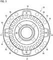
FIG. 3 is an elevational view of the clutch ring and a cap main body, where an inside thereof is viewed in the axial direction. -
FIG. 4 is an elevational view of the cap, which illustrates an outside thereof. -
FIG. 5 is an elevational view of the helical LSD, in which the clutch member alone installed therein is viewed in the axial direction. - Exemplary embodiments will be described hereinafter with reference to the appended drawings.
- Throughout the following description and the appended claims, an axis means a rotational axis of a limited-slip differential (LSD) unless otherwise described. Further, while the right and the left may be sometimes discriminated in the following description, this is merely for the convenience of explanation and therefore does not limit embodiments.
- Referring to
FIG. 1 , a helical LSD 1 is a kind of differential gear. The helical LSD 1 is rotatable about an axis C, a cap 3 is combined with an end thereof and anend cap 5 is combined with another end. Thecaps 3, 5 bear thrust force acting on theplanetary gears sun gears sun gears actuator 7 is a mechanism for driving the locking mechanism. - The helical LSD 1 is in general comprised of a generally
cylindrical casing 11, aflange 13 fixedly combined therewith or forming a unitary body therewith, theplanetary gears sun gears casing 11. Theflange 13 projects radially outward from thecasing 11 and receives torque via a ring gear combined therewith for example from an engine/motor, thereby thecasing 11 rotates about the axis C. - The
casing 11 is provided with a plurality oflong bores 15 and a plurality ofshort bores 19 both running in parallel with the axis C. Thelong bores 15 can be opened on both ends of thecasing 11 but theshort bores 19 start from one end adjacent to theend cap 5 and terminate at anend wall 27. - Each long
bore 15 houses along pinion 17 of the planetary gears and each short bore 19 houses ashort pinion 21 likewise. Thesun gears casing 11. Thelong pinions 17 and theshort pinions 21 are in mesh with each other and are further in mesh with thesun gears casing 11 through theplanetary gears sun gears sun gears - The
pinions sun gears caps 3, 5 fixed to both ends of thecasing 11 and theend wall 27 of thecasing 11. Further, friction arising from the thrust force limits rotation of thepinions - The cap 3 is in general comprised of a
clutch member 31, aclutch ring 33 and a capmain body 35, and the combination of theclutch member 31 and theclutch ring 33 constitutes a clutch. Theclutch member 31 is, by means of splines for example, combined with one of thesun gears 23 and theclutch ring 33, when coupled therewith, locks thesun gear 23 relative to the cap 3, thereby locking up differential motion of the helical LSD 1. - Referring to
FIGs. 2 ,3 in combination withFIG. 1 , theclutch ring 33 is comprised of aring portion 41, the totality of which is generally ring-shaped, and a plurality oftab portions 43 projecting radially outward from thering portion 41. Thetab portions 43 are arranged in a rotationally symmetric fashion about the axis C and the number thereof is four for instance as shown in the drawings. The arrangement and the number of thetab portions 43 may be set as the same as those of thelong pinions 17. The totality of theclutch ring 33 may be produced by forging and machining for example. - The whole of the cap
main body 35 is shaped like a round pan, which has an inner face (first face) 45 in contact with thecasing 11 and an outer face (second face) 47 axially opposed to the inner face, and around the center thereof formed is a recedingportion 49 receding from thefirst face 45 toward thesecond face 47 so as to receive theclutch ring 33. Therecess portion 49 is generally round according to theclutch ring 33 but has a plurality ofdock portions 51 respectively receiving thetab portions 43. Theclutch ring 33 is received in therecess portion 49 and is movable therein along the axis C and yet movable slightly in the circumferential direction. - Further referring to
FIG. 4 , the capmain body 35 is provided with one ormore openings 37 opened on thesecond face 47. Theopenings 37 are respectively spatially in communication with thedock portions 51 to allow access from the exterior to thetab portions 43 in thedock portions 51. Theopenings 37 may be opened toward all thedock portions 51, or alternatively may be limited to somedock portions 51. Theplural openings 37 are preferably rotationally symmetric about the axis C. Apressure plate 39 to be driven by theactuator 7 in the direction of the axis C intrudes through theopenings 37 into thedock portions 51 and is there combined with thetab portions 43, so that theactuator 7 is enabled to drive theclutch ring 33. - As best shown in
FIG. 2 , bothside faces 55 of therespective tab portions 43, which are somehow directed in the circumferential directions, are not perpendicular to the circumferential directions but inclined toward the capmain body 35. Correspondingly,inner faces 57 of therespective dock portions 51 are not perpendicular to the circumferential directions but inclined toward thefirst face 45. The combination of these oblique side faces 55 andinner faces 57, when getting contact with each other, constitutes a cam for pressing theclutch ring 33 in the direction of the axis C toward theclutch member 31. Thetab 43 may be formed sufficiently thick in the direction of the axis C so as to prevent buckling caused by the load from the pressure force, and the side faces 55 of thetab portions 43 may be formed longer in length in the axial direction than theinner faces 57 of thedock portions 51. - As best shown in
FIG. 3 , while thefirst face 45 of the capmain body 35 is scooped radially outward at thedock portions 51, intervening betweenadjacent dock portions 51 arebase portions 53 that respectively stretch continuously therebetween. Each of thebase portions 53 has a shape capable of having axially close contact with thecasing 11. Thebase portions 53 may be provided with through-holes 65 axially penetrating thebase portions 53 and are fixed with thecasing 11 by means of a plurality of bolts 69 (seeFIG. 1 ). While thebase portions 53 bear counter-force by the cam, as they are in continuity in the circumferential direction and as they are to be integrated with the casing, thebase portions 53 effectively prevent the capmain body 35 from deforming or being damaged. - Referring to
FIG. 5 , thecasing 11 is provided with tap holes 67 corresponding to the through-holes 65 of the capmain body 35, and the long bores 15 respectively housing thelong pinions 17 are located between the tap holes 67. Specifically, the locations of thelong bores 15 and thelong pinions 17 are corresponding to the locations of thetab portions 43 and thedock portions 51 in the circumferential direction. While the locations of theshort bores 19 and theshort pinions 21 necessarily overlap the locations of the tap holes 67 and the through-holes 65 in the circumferential direction, as being understood fromFIG. 1 , theend wall 27 is sufficiently apart from the contact face on the capmain body 35 so that the tap holes 67 do not interfere with theshort bores 19. It is unnecessary to dispose the tap holes 67 radially outward and therefore the present embodiment is advantageous in size reduction of the helical LSD 1. - Referring again to
FIG. 5 , theclutch member 31 is, at its internal periphery for instance, combinable with thesun gear 23. This coupling may be established by splines for example, or alternatively they may be a unitary body. Theclutch member 31, around its outer periphery, may overlap with thelong pinions 17 and may thereby bear the thrust force acting on thelong pinions 17. Further referring toFIG. 1 in combination, theclutch member 31 is elongated along the bore portion of thesun gear 23 to pass through the internal periphery of theclutch ring 33, thereby getting in contact with the capmain body 35. Theclutch member 31 may be directly in contact with the capmain body 35 or alternatively may have any thrust bearing or washer or such interposed therebetween. Specifically, the capmain body 35 can bear the thrust force acting on thelong pinions 17 via theclutch member 31. - The
clutch member 31 and theclutch ring 33 are provided with mutually engageableclutch teeth clutch member 31 is combined with thesun gear 23 and theclutch ring 33 engages with the cap 3 by means of thetab portions 43, when theclutch teeth sun gear 23 is locked to thecasing 11 and therefore the differential motion of the helical LSD 1 gets locked. A return spring may be interposed between theclutch member 31 and theclutch ring 33, or between theclutch ring 33 and thecasing 11, to urge theclutch teeth - The
actuator 7 is, as described already, a means for driving the locking mechanism and is formed of an electromagnet for example. Alternatively, any hydraulic device, any pneumatic device, a combination of a motor and a cam device or any proper means that produces driving force in the axial direction is applicable to theactuator 7. Theactuator 7 may be fixed to a stationary member or slidably fit on the bore portion of the capmain body 35 and be anti-rotated. - According to the present embodiment, when the
actuator 7 does not exert driving force on theclutch ring 33, theclutch ring 33 is disengaged from theclutch member 31 and differential motion between the sun gears 23, 25 is enabled. As theactuator 7 presses, via thepressure plate 39, theclutch ring 33 in the direction of the axis C, theclutch teeth clutch ring 33 is connected to theclutch member 31, thereby locking the differential motion. - Then the side faces 55 of the
tab portions 43 butt against the inner faces 57 of thedock portions 51 to convert part of the torque acting on the helical LSD 1 into thrust force, thereby assisting this connection. As theactuator 7 can use this assisting force, theactuator 7 can, without keeping exerting great driving force, preserve the connection between theclutch ring 33 and theclutch member 31. - While relatively great force acts on the side faces 55 of the
tab portions 43 and the inner faces 57 of thedock portions 51, it merely creates simple compression or bending stress and does not produce stress concentration. As thetab portions 43 are relatively large in thickness in the principal stress direction and thebase portions 53 forming a unitary body with thecasing 11 support the internal faces 57 of thedock portions 51, both are prevented from deforming or being damaged. Further, thetab portions 43 are apart from the axis C more than theclutch teeth 63 are, and therefore the force on thetab portions 43 is kept small as being controlled by the principle of leverage even if relatively large force acts on theclutch teeth 63. - As the cam mechanism is used to assist the
actuator 7, it becomes unnecessary to use a large-sized actuator and the cam mechanism is by itself compact in the axial direction. Therefore the cap 3 capable of locking the differential motion is notably compact. - As both the
clutch member 31 and theclutch ring 33 do not have a structure bulging out in the axial direction, they can be readily produced by forging and machining. Because forging is applicable, any higher-strength material is available and therefore it assures high durability. - As the cap
main body 35 also has any structure equivalent to so-called undercuts, it can be produced by forging and machining. It is unnecessary to use any soft material that enables formation of undercuts, and instead any higher-strength material is available. This leads to high durability. - Although certain exemplary embodiments are described above, modifications and variations of the embodiments will occur to those skilled in the art, in light of the above teachings.
- A cap applicable to a helical LSD, which has a function of locking differential motion but is compact and highly durable, is provided.
Claims (4)
- A cap for use with a casing of a helical LSD rotatable about an axis to lock up differential motion, comprising:a clutch member combinable with any of sun gears of the helical LSD and including clutch teeth;a clutch ring including a ring portion including clutch teeth so as to mesh with the clutch member and one or more tab portions being unitary with and projecting radially outward from the ring portion;a cap main body fixed on an axial end of the casing, the cap main body having a first face in contact with the casing and a second face axially opposed to the first face;a receding portion of the cap main body receding from the first face toward the second face and being so dimensioned as to receive and allow the clutch ring to be axially movable, the receding portion including one or more dock portions respectively receiving the tab portions;an opening opened on the second face and in spatial communication with any of the dog portions to allow access to the tab portions;side faces of the tab portions, each of the side faces inclining toward the second face;inner faces of the dog portions inclining toward the first face so as to butt against the side faces in a circumferential direction to axially press the clutch ring toward the clutch member; andone or more base portions each having a shape capable of having axially close contact with the casing in continuity between adjacent dock portions.
- The cap of claim 1, wherein the base portions are so disposed as to axially align with short pinions of the helical LSD and each of the base portions comprises one or more bolt holes axially penetrating the base portion from the first face toward the second face.
- The cap of claim 1, wherein the side faces are longer in axial length than the inner faces.
- The cap of claim 1, wherein the clutch member is axially elongated to come in contact with the cap main body.
Applications Claiming Priority (1)
| Application Number | Priority Date | Filing Date | Title |
|---|---|---|---|
| PCT/JP2016/066164 WO2017208385A1 (en) | 2016-06-01 | 2016-06-01 | Cap with helical lsd clutch |
Publications (3)
| Publication Number | Publication Date |
|---|---|
| EP3467351A1 true EP3467351A1 (en) | 2019-04-10 |
| EP3467351A4 EP3467351A4 (en) | 2020-01-08 |
| EP3467351B1 EP3467351B1 (en) | 2021-03-10 |
Family
ID=60479220
Family Applications (1)
| Application Number | Title | Priority Date | Filing Date |
|---|---|---|---|
| EP16904010.2A Active EP3467351B1 (en) | 2016-06-01 | 2016-06-01 | Cap with helical lsd clutch |
Country Status (5)
| Country | Link |
|---|---|
| US (1) | US10801597B2 (en) |
| EP (1) | EP3467351B1 (en) |
| JP (1) | JP6539783B2 (en) |
| CN (1) | CN109073060A (en) |
| WO (1) | WO2017208385A1 (en) |
Families Citing this family (2)
| Publication number | Priority date | Publication date | Assignee | Title |
|---|---|---|---|---|
| US11892067B2 (en) * | 2021-03-05 | 2024-02-06 | Polaris Industries Inc. | Vehicle system |
| WO2024100734A1 (en) * | 2022-11-07 | 2024-05-16 | ジーケーエヌ オートモーティブ リミテッド | Driving force transmission device for vehicle |
Family Cites Families (17)
| Publication number | Priority date | Publication date | Assignee | Title |
|---|---|---|---|---|
| WO1993013335A1 (en) * | 1982-08-13 | 1993-07-08 | Chambers Robert O | Torque proportioning differential |
| JPH08152055A (en) * | 1994-11-28 | 1996-06-11 | Tochigi Fuji Ind Co Ltd | Differential device |
| JP3830992B2 (en) | 1995-09-13 | 2006-10-11 | Gkn ドライブライン トルクテクノロジー株式会社 | Differential device |
| JP2004116701A (en) * | 2002-09-27 | 2004-04-15 | Tochigi Fuji Ind Co Ltd | Clutch device |
| JP2004225811A (en) | 2003-01-23 | 2004-08-12 | Tochigi Fuji Ind Co Ltd | Differential device |
| JP4721965B2 (en) * | 2005-09-02 | 2011-07-13 | Gknドライブラインジャパン株式会社 | Clutch device and differential device using the clutch device |
| US7572202B2 (en) * | 2007-01-31 | 2009-08-11 | American Axle & Manufacturing, Inc. | Electronic locking differential with direct locking state detection system |
| DE102007043437B3 (en) * | 2007-09-12 | 2009-06-25 | Gkn Driveline International Gmbh | Locking differential with spur toothing |
| US8454471B2 (en) * | 2010-07-21 | 2013-06-04 | Ford Global Technologies, Llc | Electronic locking differential |
| US9212704B2 (en) * | 2012-04-24 | 2015-12-15 | Ford Global Technologies, Llc | Electromagnetically actuated clutch |
| JP2014009747A (en) * | 2012-06-29 | 2014-01-20 | Gkn Driveline Japan Ltd | Differential device |
| US10364850B2 (en) * | 2012-10-23 | 2019-07-30 | Ford Global Technologies, Llc | Clutch mechanism |
| BR112014032708A2 (en) * | 2013-10-15 | 2017-06-27 | Eaton Corp | differential |
| CN103644280B (en) * | 2013-12-16 | 2016-05-11 | 博深工具股份有限公司 | A kind of diff lock for assisted walk pavement cutting machine |
| US9074678B1 (en) * | 2014-04-23 | 2015-07-07 | American Axle & Manufacturing, Inc. | Axle assembly with housing portion configured for use in front and rear axle assemblies |
| US9500268B2 (en) * | 2014-12-03 | 2016-11-22 | American Axle & Manufacturing, Inc. | Locking differential assembly |
| JP6696179B2 (en) * | 2016-01-13 | 2020-05-20 | 株式会社ジェイテクト | Differential |
-
2016
- 2016-06-01 JP JP2018520274A patent/JP6539783B2/en active Active
- 2016-06-01 WO PCT/JP2016/066164 patent/WO2017208385A1/en unknown
- 2016-06-01 CN CN201680084921.8A patent/CN109073060A/en active Pending
- 2016-06-01 EP EP16904010.2A patent/EP3467351B1/en active Active
-
2018
- 2018-10-24 US US16/169,003 patent/US10801597B2/en active Active
Also Published As
| Publication number | Publication date |
|---|---|
| US20190056018A1 (en) | 2019-02-21 |
| WO2017208385A1 (en) | 2017-12-07 |
| JP6539783B2 (en) | 2019-07-03 |
| CN109073060A (en) | 2018-12-21 |
| JPWO2017208385A1 (en) | 2019-02-28 |
| EP3467351B1 (en) | 2021-03-10 |
| EP3467351A4 (en) | 2020-01-08 |
| US10801597B2 (en) | 2020-10-13 |
Similar Documents
| Publication | Publication Date | Title |
|---|---|---|
| EP3306136B1 (en) | Differential limiting device for vehicle | |
| WO2015068821A1 (en) | Power transmission device | |
| EP3181933A1 (en) | Power transmission device | |
| US10604008B2 (en) | Transfer case having a manually-operated four wheel drive locking mechanism | |
| US6907971B2 (en) | One-way clutch | |
| EP1837544B1 (en) | Power take-off having an axially movable bearing | |
| US10471826B2 (en) | Transfer case having a four wheel drive locking mechanism | |
| US10801597B2 (en) | Cap with clutch for helical LSD | |
| EP1326036B1 (en) | Noise reduction structure for power take-off unit gear assembly | |
| US20170234374A1 (en) | Actuator mechanism for transfer case | |
| JP4009429B2 (en) | Reverse input prevention clutch | |
| EP1326035A2 (en) | Low noice gear assembly | |
| US5509864A (en) | Split ring axial positioner for planetary gear assembly | |
| US8109377B2 (en) | Clutch device | |
| EP2833013B1 (en) | Clutch device | |
| US9163674B2 (en) | Final drive disconnect mechanism | |
| US3724620A (en) | Releaseable power transmitting device of the friction plate type | |
| EP0999375A1 (en) | Rotary coupling | |
| KR100692337B1 (en) | Belt type continous variable transmission | |
| JP4786290B2 (en) | Belt type continuously variable transmission | |
| US9593773B1 (en) | Vehicle gear shifter | |
| JP2008062932A (en) | Reduction gear mechanism of electric power steering device | |
| JP3556721B2 (en) | Planetary roller type power transmission | |
| US4185727A (en) | Wheel hub clutching mechanism | |
| US7051855B2 (en) | Positive engagement clutch |
Legal Events
| Date | Code | Title | Description |
|---|---|---|---|
| STAA | Information on the status of an ep patent application or granted ep patent |
Free format text: STATUS: THE INTERNATIONAL PUBLICATION HAS BEEN MADE |
|
| PUAI | Public reference made under article 153(3) epc to a published international application that has entered the european phase |
Free format text: ORIGINAL CODE: 0009012 |
|
| STAA | Information on the status of an ep patent application or granted ep patent |
Free format text: STATUS: REQUEST FOR EXAMINATION WAS MADE |
|
| 17P | Request for examination filed |
Effective date: 20181012 |
|
| AK | Designated contracting states |
Kind code of ref document: A1 Designated state(s): AL AT BE BG CH CY CZ DE DK EE ES FI FR GB GR HR HU IE IS IT LI LT LU LV MC MK MT NL NO PL PT RO RS SE SI SK SM TR |
|
| AX | Request for extension of the european patent |
Extension state: BA ME |
|
| DAV | Request for validation of the european patent (deleted) | ||
| DAX | Request for extension of the european patent (deleted) | ||
| A4 | Supplementary search report drawn up and despatched |
Effective date: 20191211 |
|
| RIC1 | Information provided on ipc code assigned before grant |
Ipc: F16H 48/24 20060101AFI20191205BHEP |
|
| RAP1 | Party data changed (applicant data changed or rights of an application transferred) |
Owner name: GKN AUTOMOTIVE LTD. |
|
| RAP1 | Party data changed (applicant data changed or rights of an application transferred) |
Owner name: GKN AUTOMOTIVE LIMITED |
|
| GRAP | Despatch of communication of intention to grant a patent |
Free format text: ORIGINAL CODE: EPIDOSNIGR1 |
|
| STAA | Information on the status of an ep patent application or granted ep patent |
Free format text: STATUS: GRANT OF PATENT IS INTENDED |
|
| INTG | Intention to grant announced |
Effective date: 20201007 |
|
| GRAS | Grant fee paid |
Free format text: ORIGINAL CODE: EPIDOSNIGR3 |
|
| GRAA | (expected) grant |
Free format text: ORIGINAL CODE: 0009210 |
|
| STAA | Information on the status of an ep patent application or granted ep patent |
Free format text: STATUS: THE PATENT HAS BEEN GRANTED |
|
| AK | Designated contracting states |
Kind code of ref document: B1 Designated state(s): AL AT BE BG CH CY CZ DE DK EE ES FI FR GB GR HR HU IE IS IT LI LT LU LV MC MK MT NL NO PL PT RO RS SE SI SK SM TR |
|
| REG | Reference to a national code |
Ref country code: GB Ref legal event code: FG4D |
|
| REG | Reference to a national code |
Ref country code: AT Ref legal event code: REF Ref document number: 1370151 Country of ref document: AT Kind code of ref document: T Effective date: 20210315 Ref country code: CH Ref legal event code: EP |
|
| REG | Reference to a national code |
Ref country code: IE Ref legal event code: FG4D |
|
| REG | Reference to a national code |
Ref country code: DE Ref legal event code: R096 Ref document number: 602016054267 Country of ref document: DE |
|
| REG | Reference to a national code |
Ref country code: LT Ref legal event code: MG9D |
|
| PG25 | Lapsed in a contracting state [announced via postgrant information from national office to epo] |
Ref country code: HR Free format text: LAPSE BECAUSE OF FAILURE TO SUBMIT A TRANSLATION OF THE DESCRIPTION OR TO PAY THE FEE WITHIN THE PRESCRIBED TIME-LIMIT Effective date: 20210310 Ref country code: FI Free format text: LAPSE BECAUSE OF FAILURE TO SUBMIT A TRANSLATION OF THE DESCRIPTION OR TO PAY THE FEE WITHIN THE PRESCRIBED TIME-LIMIT Effective date: 20210310 Ref country code: GR Free format text: LAPSE BECAUSE OF FAILURE TO SUBMIT A TRANSLATION OF THE DESCRIPTION OR TO PAY THE FEE WITHIN THE PRESCRIBED TIME-LIMIT Effective date: 20210611 Ref country code: NO Free format text: LAPSE BECAUSE OF FAILURE TO SUBMIT A TRANSLATION OF THE DESCRIPTION OR TO PAY THE FEE WITHIN THE PRESCRIBED TIME-LIMIT Effective date: 20210610 Ref country code: LT Free format text: LAPSE BECAUSE OF FAILURE TO SUBMIT A TRANSLATION OF THE DESCRIPTION OR TO PAY THE FEE WITHIN THE PRESCRIBED TIME-LIMIT Effective date: 20210310 Ref country code: BG Free format text: LAPSE BECAUSE OF FAILURE TO SUBMIT A TRANSLATION OF THE DESCRIPTION OR TO PAY THE FEE WITHIN THE PRESCRIBED TIME-LIMIT Effective date: 20210610 |
|
| REG | Reference to a national code |
Ref country code: AT Ref legal event code: MK05 Ref document number: 1370151 Country of ref document: AT Kind code of ref document: T Effective date: 20210310 |
|
| REG | Reference to a national code |
Ref country code: NL Ref legal event code: MP Effective date: 20210310 |
|
| PG25 | Lapsed in a contracting state [announced via postgrant information from national office to epo] |
Ref country code: RS Free format text: LAPSE BECAUSE OF FAILURE TO SUBMIT A TRANSLATION OF THE DESCRIPTION OR TO PAY THE FEE WITHIN THE PRESCRIBED TIME-LIMIT Effective date: 20210310 Ref country code: LV Free format text: LAPSE BECAUSE OF FAILURE TO SUBMIT A TRANSLATION OF THE DESCRIPTION OR TO PAY THE FEE WITHIN THE PRESCRIBED TIME-LIMIT Effective date: 20210310 Ref country code: SE Free format text: LAPSE BECAUSE OF FAILURE TO SUBMIT A TRANSLATION OF THE DESCRIPTION OR TO PAY THE FEE WITHIN THE PRESCRIBED TIME-LIMIT Effective date: 20210310 |
|
| PG25 | Lapsed in a contracting state [announced via postgrant information from national office to epo] |
Ref country code: NL Free format text: LAPSE BECAUSE OF FAILURE TO SUBMIT A TRANSLATION OF THE DESCRIPTION OR TO PAY THE FEE WITHIN THE PRESCRIBED TIME-LIMIT Effective date: 20210310 |
|
| PG25 | Lapsed in a contracting state [announced via postgrant information from national office to epo] |
Ref country code: SM Free format text: LAPSE BECAUSE OF FAILURE TO SUBMIT A TRANSLATION OF THE DESCRIPTION OR TO PAY THE FEE WITHIN THE PRESCRIBED TIME-LIMIT Effective date: 20210310 Ref country code: AT Free format text: LAPSE BECAUSE OF FAILURE TO SUBMIT A TRANSLATION OF THE DESCRIPTION OR TO PAY THE FEE WITHIN THE PRESCRIBED TIME-LIMIT Effective date: 20210310 Ref country code: EE Free format text: LAPSE BECAUSE OF FAILURE TO SUBMIT A TRANSLATION OF THE DESCRIPTION OR TO PAY THE FEE WITHIN THE PRESCRIBED TIME-LIMIT Effective date: 20210310 Ref country code: CZ Free format text: LAPSE BECAUSE OF FAILURE TO SUBMIT A TRANSLATION OF THE DESCRIPTION OR TO PAY THE FEE WITHIN THE PRESCRIBED TIME-LIMIT Effective date: 20210310 |
|
| PG25 | Lapsed in a contracting state [announced via postgrant information from national office to epo] |
Ref country code: IS Free format text: LAPSE BECAUSE OF FAILURE TO SUBMIT A TRANSLATION OF THE DESCRIPTION OR TO PAY THE FEE WITHIN THE PRESCRIBED TIME-LIMIT Effective date: 20210710 Ref country code: PL Free format text: LAPSE BECAUSE OF FAILURE TO SUBMIT A TRANSLATION OF THE DESCRIPTION OR TO PAY THE FEE WITHIN THE PRESCRIBED TIME-LIMIT Effective date: 20210310 Ref country code: PT Free format text: LAPSE BECAUSE OF FAILURE TO SUBMIT A TRANSLATION OF THE DESCRIPTION OR TO PAY THE FEE WITHIN THE PRESCRIBED TIME-LIMIT Effective date: 20210712 Ref country code: RO Free format text: LAPSE BECAUSE OF FAILURE TO SUBMIT A TRANSLATION OF THE DESCRIPTION OR TO PAY THE FEE WITHIN THE PRESCRIBED TIME-LIMIT Effective date: 20210310 Ref country code: SK Free format text: LAPSE BECAUSE OF FAILURE TO SUBMIT A TRANSLATION OF THE DESCRIPTION OR TO PAY THE FEE WITHIN THE PRESCRIBED TIME-LIMIT Effective date: 20210310 |
|
| REG | Reference to a national code |
Ref country code: DE Ref legal event code: R097 Ref document number: 602016054267 Country of ref document: DE |
|
| PLBE | No opposition filed within time limit |
Free format text: ORIGINAL CODE: 0009261 |
|
| STAA | Information on the status of an ep patent application or granted ep patent |
Free format text: STATUS: NO OPPOSITION FILED WITHIN TIME LIMIT |
|
| PG25 | Lapsed in a contracting state [announced via postgrant information from national office to epo] |
Ref country code: ES Free format text: LAPSE BECAUSE OF FAILURE TO SUBMIT A TRANSLATION OF THE DESCRIPTION OR TO PAY THE FEE WITHIN THE PRESCRIBED TIME-LIMIT Effective date: 20210310 Ref country code: MC Free format text: LAPSE BECAUSE OF FAILURE TO SUBMIT A TRANSLATION OF THE DESCRIPTION OR TO PAY THE FEE WITHIN THE PRESCRIBED TIME-LIMIT Effective date: 20210310 Ref country code: DK Free format text: LAPSE BECAUSE OF FAILURE TO SUBMIT A TRANSLATION OF THE DESCRIPTION OR TO PAY THE FEE WITHIN THE PRESCRIBED TIME-LIMIT Effective date: 20210310 Ref country code: AL Free format text: LAPSE BECAUSE OF FAILURE TO SUBMIT A TRANSLATION OF THE DESCRIPTION OR TO PAY THE FEE WITHIN THE PRESCRIBED TIME-LIMIT Effective date: 20210310 |
|
| REG | Reference to a national code |
Ref country code: CH Ref legal event code: PL |
|
| 26N | No opposition filed |
Effective date: 20211213 |
|
| GBPC | Gb: european patent ceased through non-payment of renewal fee |
Effective date: 20210610 |
|
| PG25 | Lapsed in a contracting state [announced via postgrant information from national office to epo] |
Ref country code: SI Free format text: LAPSE BECAUSE OF FAILURE TO SUBMIT A TRANSLATION OF THE DESCRIPTION OR TO PAY THE FEE WITHIN THE PRESCRIBED TIME-LIMIT Effective date: 20210310 |
|
| REG | Reference to a national code |
Ref country code: BE Ref legal event code: MM Effective date: 20210630 |
|
| PG25 | Lapsed in a contracting state [announced via postgrant information from national office to epo] |
Ref country code: LU Free format text: LAPSE BECAUSE OF NON-PAYMENT OF DUE FEES Effective date: 20210601 |
|
| PG25 | Lapsed in a contracting state [announced via postgrant information from national office to epo] |
Ref country code: LI Free format text: LAPSE BECAUSE OF NON-PAYMENT OF DUE FEES Effective date: 20210630 Ref country code: IT Free format text: LAPSE BECAUSE OF FAILURE TO SUBMIT A TRANSLATION OF THE DESCRIPTION OR TO PAY THE FEE WITHIN THE PRESCRIBED TIME-LIMIT Effective date: 20210310 Ref country code: IE Free format text: LAPSE BECAUSE OF NON-PAYMENT OF DUE FEES Effective date: 20210601 Ref country code: GB Free format text: LAPSE BECAUSE OF NON-PAYMENT OF DUE FEES Effective date: 20210610 Ref country code: CH Free format text: LAPSE BECAUSE OF NON-PAYMENT OF DUE FEES Effective date: 20210630 |
|
| PG25 | Lapsed in a contracting state [announced via postgrant information from national office to epo] |
Ref country code: IS Free format text: LAPSE BECAUSE OF FAILURE TO SUBMIT A TRANSLATION OF THE DESCRIPTION OR TO PAY THE FEE WITHIN THE PRESCRIBED TIME-LIMIT Effective date: 20210710 Ref country code: FR Free format text: LAPSE BECAUSE OF NON-PAYMENT OF DUE FEES Effective date: 20210630 |
|
| PG25 | Lapsed in a contracting state [announced via postgrant information from national office to epo] |
Ref country code: BE Free format text: LAPSE BECAUSE OF NON-PAYMENT OF DUE FEES Effective date: 20210630 |
|
| PG25 | Lapsed in a contracting state [announced via postgrant information from national office to epo] |
Ref country code: CY Free format text: LAPSE BECAUSE OF FAILURE TO SUBMIT A TRANSLATION OF THE DESCRIPTION OR TO PAY THE FEE WITHIN THE PRESCRIBED TIME-LIMIT Effective date: 20210310 |
|
| PG25 | Lapsed in a contracting state [announced via postgrant information from national office to epo] |
Ref country code: HU Free format text: LAPSE BECAUSE OF FAILURE TO SUBMIT A TRANSLATION OF THE DESCRIPTION OR TO PAY THE FEE WITHIN THE PRESCRIBED TIME-LIMIT; INVALID AB INITIO Effective date: 20160601 |
|
| PG25 | Lapsed in a contracting state [announced via postgrant information from national office to epo] |
Ref country code: MK Free format text: LAPSE BECAUSE OF FAILURE TO SUBMIT A TRANSLATION OF THE DESCRIPTION OR TO PAY THE FEE WITHIN THE PRESCRIBED TIME-LIMIT Effective date: 20210310 |
|
| PG25 | Lapsed in a contracting state [announced via postgrant information from national office to epo] |
Ref country code: TR Free format text: LAPSE BECAUSE OF FAILURE TO SUBMIT A TRANSLATION OF THE DESCRIPTION OR TO PAY THE FEE WITHIN THE PRESCRIBED TIME-LIMIT Effective date: 20210310 |
|
| PGFP | Annual fee paid to national office [announced via postgrant information from national office to epo] |
Ref country code: DE Payment date: 20240617 Year of fee payment: 9 |