EP3467314A2 - Screw pump - Google Patents
Screw pump Download PDFInfo
- Publication number
- EP3467314A2 EP3467314A2 EP18208219.8A EP18208219A EP3467314A2 EP 3467314 A2 EP3467314 A2 EP 3467314A2 EP 18208219 A EP18208219 A EP 18208219A EP 3467314 A2 EP3467314 A2 EP 3467314A2
- Authority
- EP
- European Patent Office
- Prior art keywords
- pump
- screw
- housing
- thread
- threads
- Prior art date
- Legal status (The legal status is an assumption and is not a legal conclusion. Google has not performed a legal analysis and makes no representation as to the accuracy of the status listed.)
- Granted
Links
- 230000007423 decrease Effects 0.000 claims abstract description 3
- 230000007704 transition Effects 0.000 claims description 16
- 230000002093 peripheral effect Effects 0.000 claims description 6
- 239000007788 liquid Substances 0.000 claims description 5
- 230000000284 resting effect Effects 0.000 claims description 3
- 230000000712 assembly Effects 0.000 claims 1
- 238000000429 assembly Methods 0.000 claims 1
- 230000006835 compression Effects 0.000 description 10
- 238000007906 compression Methods 0.000 description 10
- 238000012423 maintenance Methods 0.000 description 3
- 230000008878 coupling Effects 0.000 description 1
- 238000010168 coupling process Methods 0.000 description 1
- 238000005859 coupling reaction Methods 0.000 description 1
- 238000010586 diagram Methods 0.000 description 1
- 230000000694 effects Effects 0.000 description 1
- 239000012530 fluid Substances 0.000 description 1
- 230000008092 positive effect Effects 0.000 description 1
- 238000004804 winding Methods 0.000 description 1
Images
Classifications
-
- F—MECHANICAL ENGINEERING; LIGHTING; HEATING; WEAPONS; BLASTING
- F04—POSITIVE - DISPLACEMENT MACHINES FOR LIQUIDS; PUMPS FOR LIQUIDS OR ELASTIC FLUIDS
- F04C—ROTARY-PISTON, OR OSCILLATING-PISTON, POSITIVE-DISPLACEMENT MACHINES FOR LIQUIDS; ROTARY-PISTON, OR OSCILLATING-PISTON, POSITIVE-DISPLACEMENT PUMPS
- F04C23/00—Combinations of two or more pumps, each being of rotary-piston or oscillating-piston type, specially adapted for elastic fluids; Pumping installations specially adapted for elastic fluids; Multi-stage pumps specially adapted for elastic fluids
- F04C23/001—Combinations of two or more pumps, each being of rotary-piston or oscillating-piston type, specially adapted for elastic fluids; Pumping installations specially adapted for elastic fluids; Multi-stage pumps specially adapted for elastic fluids of similar working principle
- F04C23/003—Combinations of two or more pumps, each being of rotary-piston or oscillating-piston type, specially adapted for elastic fluids; Pumping installations specially adapted for elastic fluids; Multi-stage pumps specially adapted for elastic fluids of similar working principle having complementary function
-
- F—MECHANICAL ENGINEERING; LIGHTING; HEATING; WEAPONS; BLASTING
- F04—POSITIVE - DISPLACEMENT MACHINES FOR LIQUIDS; PUMPS FOR LIQUIDS OR ELASTIC FLUIDS
- F04C—ROTARY-PISTON, OR OSCILLATING-PISTON, POSITIVE-DISPLACEMENT MACHINES FOR LIQUIDS; ROTARY-PISTON, OR OSCILLATING-PISTON, POSITIVE-DISPLACEMENT PUMPS
- F04C18/00—Rotary-piston pumps specially adapted for elastic fluids
- F04C18/08—Rotary-piston pumps specially adapted for elastic fluids of intermeshing-engagement type, i.e. with engagement of co-operating members similar to that of toothed gearing
- F04C18/082—Details specially related to intermeshing engagement type pumps
- F04C18/084—Toothed wheels
-
- F—MECHANICAL ENGINEERING; LIGHTING; HEATING; WEAPONS; BLASTING
- F04—POSITIVE - DISPLACEMENT MACHINES FOR LIQUIDS; PUMPS FOR LIQUIDS OR ELASTIC FLUIDS
- F04C—ROTARY-PISTON, OR OSCILLATING-PISTON, POSITIVE-DISPLACEMENT MACHINES FOR LIQUIDS; ROTARY-PISTON, OR OSCILLATING-PISTON, POSITIVE-DISPLACEMENT PUMPS
- F04C18/00—Rotary-piston pumps specially adapted for elastic fluids
- F04C18/08—Rotary-piston pumps specially adapted for elastic fluids of intermeshing-engagement type, i.e. with engagement of co-operating members similar to that of toothed gearing
- F04C18/082—Details specially related to intermeshing engagement type pumps
- F04C18/086—Carter
-
- F—MECHANICAL ENGINEERING; LIGHTING; HEATING; WEAPONS; BLASTING
- F04—POSITIVE - DISPLACEMENT MACHINES FOR LIQUIDS; PUMPS FOR LIQUIDS OR ELASTIC FLUIDS
- F04C—ROTARY-PISTON, OR OSCILLATING-PISTON, POSITIVE-DISPLACEMENT MACHINES FOR LIQUIDS; ROTARY-PISTON, OR OSCILLATING-PISTON, POSITIVE-DISPLACEMENT PUMPS
- F04C18/00—Rotary-piston pumps specially adapted for elastic fluids
- F04C18/08—Rotary-piston pumps specially adapted for elastic fluids of intermeshing-engagement type, i.e. with engagement of co-operating members similar to that of toothed gearing
- F04C18/12—Rotary-piston pumps specially adapted for elastic fluids of intermeshing-engagement type, i.e. with engagement of co-operating members similar to that of toothed gearing of other than internal-axis type
- F04C18/14—Rotary-piston pumps specially adapted for elastic fluids of intermeshing-engagement type, i.e. with engagement of co-operating members similar to that of toothed gearing of other than internal-axis type with toothed rotary pistons
- F04C18/16—Rotary-piston pumps specially adapted for elastic fluids of intermeshing-engagement type, i.e. with engagement of co-operating members similar to that of toothed gearing of other than internal-axis type with toothed rotary pistons with helical teeth, e.g. chevron-shaped, screw type
-
- F—MECHANICAL ENGINEERING; LIGHTING; HEATING; WEAPONS; BLASTING
- F04—POSITIVE - DISPLACEMENT MACHINES FOR LIQUIDS; PUMPS FOR LIQUIDS OR ELASTIC FLUIDS
- F04C—ROTARY-PISTON, OR OSCILLATING-PISTON, POSITIVE-DISPLACEMENT MACHINES FOR LIQUIDS; ROTARY-PISTON, OR OSCILLATING-PISTON, POSITIVE-DISPLACEMENT PUMPS
- F04C29/00—Component parts, details or accessories of pumps or pumping installations, not provided for in groups F04C18/00 - F04C28/00
- F04C29/12—Arrangements for admission or discharge of the working fluid, e.g. constructional features of the inlet or outlet
-
- F—MECHANICAL ENGINEERING; LIGHTING; HEATING; WEAPONS; BLASTING
- F04—POSITIVE - DISPLACEMENT MACHINES FOR LIQUIDS; PUMPS FOR LIQUIDS OR ELASTIC FLUIDS
- F04C—ROTARY-PISTON, OR OSCILLATING-PISTON, POSITIVE-DISPLACEMENT MACHINES FOR LIQUIDS; ROTARY-PISTON, OR OSCILLATING-PISTON, POSITIVE-DISPLACEMENT PUMPS
- F04C2220/00—Application
- F04C2220/10—Vacuum
- F04C2220/12—Dry running
-
- F—MECHANICAL ENGINEERING; LIGHTING; HEATING; WEAPONS; BLASTING
- F04—POSITIVE - DISPLACEMENT MACHINES FOR LIQUIDS; PUMPS FOR LIQUIDS OR ELASTIC FLUIDS
- F04C—ROTARY-PISTON, OR OSCILLATING-PISTON, POSITIVE-DISPLACEMENT MACHINES FOR LIQUIDS; ROTARY-PISTON, OR OSCILLATING-PISTON, POSITIVE-DISPLACEMENT PUMPS
- F04C2230/00—Manufacture
- F04C2230/60—Assembly methods
- F04C2230/605—Balancing
-
- F—MECHANICAL ENGINEERING; LIGHTING; HEATING; WEAPONS; BLASTING
- F04—POSITIVE - DISPLACEMENT MACHINES FOR LIQUIDS; PUMPS FOR LIQUIDS OR ELASTIC FLUIDS
- F04C—ROTARY-PISTON, OR OSCILLATING-PISTON, POSITIVE-DISPLACEMENT MACHINES FOR LIQUIDS; ROTARY-PISTON, OR OSCILLATING-PISTON, POSITIVE-DISPLACEMENT PUMPS
- F04C2240/00—Components
- F04C2240/40—Electric motor
- F04C2240/402—Plurality of electronically synchronised motors
-
- F—MECHANICAL ENGINEERING; LIGHTING; HEATING; WEAPONS; BLASTING
- F04—POSITIVE - DISPLACEMENT MACHINES FOR LIQUIDS; PUMPS FOR LIQUIDS OR ELASTIC FLUIDS
- F04C—ROTARY-PISTON, OR OSCILLATING-PISTON, POSITIVE-DISPLACEMENT MACHINES FOR LIQUIDS; ROTARY-PISTON, OR OSCILLATING-PISTON, POSITIVE-DISPLACEMENT PUMPS
- F04C2250/00—Geometry
- F04C2250/10—Geometry of the inlet or outlet
- F04C2250/101—Geometry of the inlet or outlet of the inlet
-
- F—MECHANICAL ENGINEERING; LIGHTING; HEATING; WEAPONS; BLASTING
- F04—POSITIVE - DISPLACEMENT MACHINES FOR LIQUIDS; PUMPS FOR LIQUIDS OR ELASTIC FLUIDS
- F04C—ROTARY-PISTON, OR OSCILLATING-PISTON, POSITIVE-DISPLACEMENT MACHINES FOR LIQUIDS; ROTARY-PISTON, OR OSCILLATING-PISTON, POSITIVE-DISPLACEMENT PUMPS
- F04C23/00—Combinations of two or more pumps, each being of rotary-piston or oscillating-piston type, specially adapted for elastic fluids; Pumping installations specially adapted for elastic fluids; Multi-stage pumps specially adapted for elastic fluids
- F04C23/001—Combinations of two or more pumps, each being of rotary-piston or oscillating-piston type, specially adapted for elastic fluids; Pumping installations specially adapted for elastic fluids; Multi-stage pumps specially adapted for elastic fluids of similar working principle
Definitions
- the invention relates to a screw pump with two screws.
- Each screw is provided with a first thread and a second thread, the threads each extending from a suction side to a pressure side.
- the threads are engaged with each other so that the threads are divided into a plurality of working chambers.
- the volume of the working chambers decreases from the suction side to the pressure side.
- Screw pumps of this type can be used to generate a vacuum.
- the room to be evacuated is connected to the suction side of the pump so that the pump can suck gas out of the room.
- the gas is compressed in the pump and released on the pressure side at higher pressure.
- screw pumps have a number of advantageous properties and are therefore widely used.
- the suction power ie the ability to remove a large volume of gas from a room within a short period of time, is limited.
- screw pumps are so far due to their lack of suction power regularly out of the question.
- other types of pumps such as Roots pumps.
- the invention is based on the object to introduce a screw pump with increased suction power. Based on the above-mentioned prior art, the object is achieved with the features of claim 1. Advantageous embodiments can be found in the subclaims.
- the threads each have two threads.
- the threads are preferably symmetrical to each other in the radial direction.
- the threads then have a point symmetry such that the threads can be imaged by themselves in a rotation about the screw axis by 180 °.
- the invention has recognized that the limited suction power is due, inter alia, to the fact that conventional screw pumps can not be operated at any desired high speed.
- a limitation of the rotational speed results from the fact that conventional screws have an uneven mass distribution with respect to the screw axis.
- the uneven mass distribution causes an imbalance that is difficult to control at high speeds.
- the distribution of masses is uneven because, in the case of the normal (catchy) threads of conventional screw pumps, the thread pitch already ensures asymmetric mass distribution.
- each thread has two threads, which are interlocked with each other so that they together form a shape in the manner of a double helix.
- the double-threaded threads are preferably each designed so that a related on the screw axis symmetrical design results. For each outwardly projecting element of the one thread there is therefore a corresponding element of the other thread, which lies in radial direction with respect to the screw axis. Due to the more uniform mass distribution of the double-flighted thread compared to single-start threads, it becomes possible to operate the screw pump at a higher speed, so that the suction power increases.
- the pump is preferably designed so that the two threads of a screw work in the opposite direction.
- the forces exerted by one thread in the longitudinal direction are then compensated by the other thread.
- the threads are aligned so that the suction side in the center of the screw, that is arranged between the two threads.
- the pressure sides are then formed by the outer ends of the threads, which has the particular advantage that the drive elements and bearings are exposed to the higher outlet pressure.
- the screw may also be designed so that it also has a symmetrical shape in the longitudinal direction, considering the trapped between the two outer ends of the threaded portion of the screw.
- the pump according to the invention comprises a housing in which the two screws are accommodated.
- the housing In the region of the suction side, the housing is provided with an inlet opening, in the region of the pressure side there is an outlet opening. It has been proven that it is for a high suction power of the pump It is important to design the inlet opening and the suction side of the pump so that a high volume flow can enter the pump.
- the housing is preferably designed so that it has a first housing portion and a second housing portion in the region of a thread, wherein in the first housing portion has a suction gap between the housing and the thread, and wherein the housing in the second housing portion terminates with the thread.
- the fact that the housing terminates with the thread is to be understood so that the leakage gap which necessarily exists between the housing and the thread in the case of dry running pumps is as small as possible (minimum radial distance).
- the aim today is a value of less than 0.2 mm, preferably about 0.1 mm for the radial minimum distance.
- the second housing section preferably connects to the pressure side of the thread.
- the inlet opening of the housing is also regularly arranged.
- the screw is then surrounded only in the peripheral portion of the housing, which still remains next to the inlet opening and the second screw. If there is a suction gap between the housing and the thread in the first housing section, it is to be understood that in at least a partial section of this peripheral section there is a radial distance between the thread and the housing which is larger is the minimum radial distance.
- the radial distance in the region of the suction gap is at least a factor of 50, preferably a factor of 100, more preferably a factor of 200, greater than the radial minimum distance.
- the suction gap has the effect that the sucked gas can not only enter the working chambers in the radial direction, but can also move through the suction gap from one working chamber into the next working chamber.
- the working chamber can fill faster, which has a positive effect on the suction power.
- the suction gap extends adjacent to the input opening in the circumferential direction over at least 10%, preferably at least 20%, more preferably at least 30% of the peripheral portion with which the housing surrounds the screw in the second housing section.
- the suction gap can extend over a correspondingly larger peripheral portion of, for example, at least 50%.
- the suction gap preferably extends over at least 20%, more preferably over at least 30%, more preferably over at least 40% of the length of the thread.
- the second housing portion is significantly shorter than the length of the thread and extends, for example, not more than 80%, preferably not more than 70%, more preferably not more than 60 % of the length of the thread.
- the extent of the suction gap in the longitudinal direction may substantially correspond to the screw portion occupied by the first 360 ° turn of the thread. The thread therefore has a large pitch in the inlet area.
- the first 360 ° turn viewed from the suction side, assumes at least 20%, preferably at least 30%, more preferably at least 40%, of the length of the thread.
- each thread of the double-threaded thread preferably comprises at least three, more preferably at least four full 360 ° windings.
- a transition edge may be formed. Once the thread terminates with the transition edge, the working chamber is closed and the actual compression begins. If the transition edge were aligned parallel to the thread through which the termination occurs, the chamber would be closed abruptly. This would be good for the efficiency of the pump, but also increases the noise level.
- the transition edge is therefore oriented to include an angle with the circumferential direction corresponding to the thread pitch, the angle being smaller than the thread pitch.
- the housing is provided with a large inlet opening.
- the entrance opening may be greater than 60%, preferably 80%, more preferably 100% of the cross-sectional area of the screw.
- the cross-sectional area of the screw indicates the contour defined by the screw. Based on this contour, which is regularly cylindrical, the radial distances between the thread and the housing can be determined.
- a distance between the inner ends of the two threads of a screw can be provided. As a result, additional space is gained through which the gas can also enter the working chambers in the longitudinal direction.
- the printed pages are regularly formed by the outer end of the threads, which means that the printed pages are spaced apart.
- a conduit is provided which extends from the pressure side to an outlet opening of the pump.
- the line is a bore which is formed between the two screws of the pump in the pump housing, wherein the bore is further preferably at least partially disposed within a resting on both screws tangential surface.
- the pump can be designed so that the two screws can be released together with the drive as a unit from the pump housing. This offers the possibility to install the pump firmly in a larger system, in particular the inlet opening and the outlet opening the pump housing can be firmly connected to the corresponding piping of the system. When maintenance or repair becomes necessary, the connections between the pump housing and the system remain and only the screw and drive unit is released from the pump housing and replaced with another unit. This avoids long downtime during maintenance and repair.
- the screws are each provided at their end remote from the drive with a bearing which is slidably received in a bearing receptacle of the pump housing.
- the bearing is released from the bearing mount and is removed with it out of the pump housing.
- the pump according to the invention is preferably dimensioned so that it reaches an intake capacity of more than 5000 m 3 / h and thereby can compress the gas from 1 mbar to 100 mbar.
- the diameter of the screws is preferably greater than 20 cm.
- the pump can be designed for operation at a speed of more than 10,000 rpm.
- the screw pump according to the invention By combining a high suction power with a large compression, the screw pump according to the invention opens up applications that were previously inaccessible to the screw pumps.
- a pump arrangement of two pumps connected in series is usually used, the first pump usually being used as a booster pump and the following one Pump is referred to as a backing pump.
- the invention accordingly relates to a pump arrangement comprising a booster pump and a fore pump in which the booster pump is a screw pump according to the invention.
- a pump arrangement in which a screw pump is used as a booster pump, has independent inventive content, even without the threads of the screws are formedteilteil.
- the screw pump according to the invention provides a considerably higher compression.
- the booster pump can suck in substantially the maximum possible volume flow and the pressure is kept constant at a low value of, for example, less than 1 mbar
- classical single-stage Roots pumps only provide a compression by a factor of 10.
- the volume flow through the subsequent backing pump is therefore according to the gas law only by a factor of 10 smaller than the volume flow through the booster pump.
- the screw pump according to the invention provides in the stationary operating state, in which substantially the maximum possible volume is sucked in and the pressure is kept constant below 1 mbar, a compression by at least a factor of 50 or even a factor of 100. This results in completely new possibilities in the design of the pump assembly.
- the volume flow through the backing pump can be smaller by at least a factor of 50, preferably at least 100, than the volume flow through the booster pump.
- the volume flow at the inlet of the booster pump in the stationary operating state is preferably greater than 1000 m 3 / h, more preferably greater than 5000 m 3 / h.
- the use of the screw pump according to the invention as a booster pump also opens the possibility to use a liquid ring vacuum pump as a fore pump.
- Liquid ring vacuum pumps are not suitable for pressures below the vapor pressure of the working fluid. In general, therefore, these pumps can not be used for pressures below 30 mbar.
- the screw pump according to the invention comes to an outlet pressure of more than 30 mbar, even if the inlet pressure is below 1 mbar. The invention thus makes it possible to use a liquid ring vacuum pump as the fore pump.
- the invention also relates to a screw for such a screw pump.
- the screw comprises two threads each extending from a suction side to a pressure side.
- the screw is characterized in that the threads each have two threads, wherein the threads are preferably symmetrical to each other in the radial direction.
- the screw can with further features are developed, which are described with reference to the pump according to the invention.
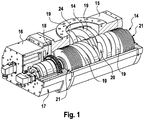
- a pump according to the invention in Fig. 1 includes two screws 14 received in a pump housing 15. One of the screws 14 is visible due to the pump housing 15 is not fully shown over the entire length, while the other screw 14 is substantially hidden by the pump housing 15. The two screws 14 are in engagement with each other, which means that the thread projections of a screw 14 in the recess between two threaded projections of the other screw 14 engage.
- the pump comprises a control and drive unit 16 in which an electronically controlled drive motor 17 is arranged for each of the screws 14.
- the electronic control of the drive motors 17 is set up so that the two screws 14 run completely synchronously with each other without the thread projections of the screws 14 touching each other.
- the two screws 14 are each equipped with a gear 18.
- the gears 18 are engaged with each other and cause a forced coupling of the two screws 14 in the event that the electronic synchronization of the screws 14 fails.
- Each screw 14 is provided with two threads 19 so that the pump has a total of four threads 19.
- the threads 19 each extend from a suction side 20 in the center of the screw 14 to a pressure side 21 at the outer ends of the screw 14.
- the two threads of a screw 14 are oriented in opposite directions, so that they work from the suction side 20 to the pressure side 21 out ,
- Each of the threads 19 comprises a first thread 22 and a second thread 23.
- the threads 19 are thus double-threaded in the sense that the threads 22, 23 are interlocked with each other so that together they form a double helical shape.
- the two threads 22, 23 are shaped so that the threads 19 are symmetrical in the radial direction. Looking at the screw 14 from the pressure side of the first thread 19 to the pressure side of second thread 19, so the screw 14 also has a longitudinal symmetry.
- the threads 19 are designed so that in the region of the suction side 20, a larger volume between two adjacent thread projections is included as in the region of the pressure side 21.
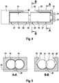
- the housing 15 of the pump is provided with an inlet opening 24 which is arranged to provide access to the suction sides 20 of all four threads 19.
- the inlet opening 24 has a large cross-section.
- the cross-sectional area of the inlet opening 24 is greater than the circular contour spanned by a screw 14.
- a suction gap 25 is formed on the housing 15 of the pump, which adjoins the inlet opening 24 and follows the contour of the screw 14 in the circumferential direction.
- the longitudinal direction of the suction gap 25 extends approximately over half the length of the thread 19 between the suction side 20 and the pressure side 21.
- the dimension of the suction gap 25 varies with the inlet opening, the farther the inlet opening 24 extends at the relevant site to the side , the shorter is the extent of the suction gap 25 in the circumferential direction at this point.
- the Suction gap 25 At the widest point of the inlet opening 24 extends the Suction gap 25 over a circumferential angle of about 45 °.
- the suction gap 24 extends over a circumferential angle of approximately 120 °.
- the dimension of the suction gap 25 in the radial direction corresponds to the distance between the pump housing 15 and the contour of the screw 14 in this area. This distance is on the order of about 10 mm.
- the gas is not limited to entering the working chambers in the radial direction, but the gas can also move through a thread projection into the working chamber through the suction gap. The volume flow into the working chamber is thereby further increased.
- Another contribution to increasing the volume flow into the working chamber is achieved in that there is a gap between the suction side 20 of the first thread 19 of a screw 14 and the suction side 20 of the second thread 19 of the screw 14. As a result, 14 space remains in the center of the screw, through which the gas can also enter in the radial direction in the working chamber.
- the distance between the housing and the contour of the screw 14 is as small as is technically possible (radial minimum distance).
- the compression takes place and leakage flow from one working chamber into the next working chamber is undesirable.
- a transition edge 28 is formed at the transition from the first housing section 26 to the second housing section 27, a transition edge 28 is formed.
- the transition edge 28 extends in the circumferential direction over the entire suction gap 25 and defines the transition from the suction gap 25 to the second housing portion 27, in which there is the minimum radial distance between the housing 15 and the screw 14.
- the compression begins as soon as the working chamber has merged into the second housing section, as soon as the thread projection which delimits the working chamber towards the suction side has concluded with the transition edge 28.
- the transition edge 28 is arranged so that the termination between the thread projection and the transition edge 28 takes place at a time when the working chamber still has its maximum volume.
- the transition edge 28 includes an angle with the transverse direction, which is smaller than the pitch of the thread projection, which terminates with the transition edge 28. This ensures that the conclusion between the thread projection and the transition edge 28 is not abrupt, but extends over a short period of time. This reduces the operating noise of the pump.
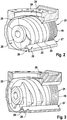
- the gas On the pressure side 21 of the thread 19, the gas is discharged from the working chamber. Through a bore 29 in the pump housing 15, the compressed gas is brought together from the outer pressure sides 21 to a central outlet opening.
- the outlet opening which is not visible in the figures, is disposed opposite the inlet opening 24.
- the bore 29 is like the FIGS. 2, 3 and 5 show integrated into the pump housing 15 and extends between the two screws 14, wherein the line 29 is partially disposed within a resting on both screws 14 tangential surface 35.
- the pump according to the invention is constructed so that the control and drive unit 16 together with the screws 14 forms a structural unit, which can be pulled out of the housing 15 as such. If maintenance or repair is required, the assembly can be replaced without having to dislodge the pump housing 15 from the plant environment.
- a bearing 31 is arranged which sits firmly on the shaft and is slidably received in a bearing receptacle 34 of the pump housing 15.
- the bearing 31 is released from the bearing receptacle 34 and is also removed from the housing 15.
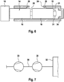
- FIG. 7 An application example of a screw pump according to the invention is in Fig. 7 shown where a pump assembly of a booster pump 30 and a backing pump 33 is connected to a space to be evacuated 32.
- the booster pump 30 is a screw pump according to the invention
- the fore pump 33 is a liquid ring vacuum pump.
- the pump arrangement is dimensioned so that from the space 32, a volume flow of 4000 m 3 / h can be sucked to keep the pressure in the space 32 at 0.5 mbar constant.
- the booster pump 30, whose screws 14 have a diameter of about 25 cm, operated at a speed of about 15,000 rpm.
- a pressure of about 50 mbar At the output of the booster pump 30 and thus at the input of the fore pump 33 is a pressure of about 50 mbar.
- this means for the backing pump 33 a volume flow of 400 m 3 / h.
- the backing pump 33 compresses this volume flow to atmospheric pressure and releases it to the environment.
Abstract
Schraubenpumpe mit zwei Schrauben (14), bei der jede Schraube (14) ein erstes Gewinde (19) und ein zweites Gewinde (19) aufweist. Die Gewinde (19) erstrecken sich jeweils von einer Saugseite (20) zu einer Druckseite (21) und stehen miteinander in Eingriff, so dass die Gewinde (19) in eine Mehrzahl von Arbeitskammern unterteilt sind, deren Volumen von der Saugseite (20) zu der Druckseite (21) abnimmt. Die Gewinde (19) weisen zwei Gewindegänge auf und das Gehäuse (15) ist mit einer Eingangsöffnung (24) versehen, die größer ist als 60 % der Querschnittsfläche des Gewindes (19).

Description
Die Erfindung betrifft eine Schraubenpumpe mit zwei Schrauben. Jede Schraube ist mit einem ersten Gewinde und einem zweiten Gewinde ausgestattet, wobei die Gewinde sich jeweils von einer Saugseite zu einer Druckseite erstrecken. Die Gewinde stehen miteinander in Eingriff, so dass die Gewinde in eine Mehrzahl von Arbeitskammern unterteilt sind. Das Volumen der Arbeitskammern nimmt jeweils von der Saugseite zu der Druckseite ab.The invention relates to a screw pump with two screws. Each screw is provided with a first thread and a second thread, the threads each extending from a suction side to a pressure side. The threads are engaged with each other so that the threads are divided into a plurality of working chambers. The volume of the working chambers decreases from the suction side to the pressure side.
Schraubenpumpen dieser Art können zum Erzeugen eines Vakuums genutzt werden. Der zu evakuierende Raum wird an die Saugseite der Pumpe angeschlossen, so dass die Pumpe Gas aus dem Raum ansaugen kann. Das Gas wird in der Pumpe komprimiert und auf der Druckseite bei höherem Druck wieder abgegeben.Screw pumps of this type can be used to generate a vacuum. The room to be evacuated is connected to the suction side of the pump so that the pump can suck gas out of the room. The gas is compressed in the pump and released on the pressure side at higher pressure.
Diese Schraubenpumpen haben eine Reihe von vorteilhaften Eigenschaften und werden deswegen in großem Umfang eingesetzt. Eingeschränkt im Vergleich zu anderen Pumpen ist aber die Saugleistung, also die Fähigkeit innerhalb eines kurzen Zeitraums ein großes Volumen an Gas aus einem Raum abzuführen. Für Anwendungen, bei denen dies gefordert ist, kommen Schraubenpumpen aufgrund ihrer mangelnden Saugleistung bislang regelmäßig nicht in Betracht. Stattdessen werden andere Arten von Pumpen verwendet wie etwa Wälzkolbenpumpen.These screw pumps have a number of advantageous properties and are therefore widely used. However, in comparison with other pumps, the suction power, ie the ability to remove a large volume of gas from a room within a short period of time, is limited. For applications where this is required, screw pumps are so far due to their lack of suction power regularly out of the question. Instead, other types of pumps are used, such as Roots pumps.
Der Erfindung liegt die Aufgabe zu Grunde, eine Schraubenpumpe mit erhöhter Saugleistung vorzustellen. Ausgehend vom eingangs genannten Stand der Technik wird die Aufgabe gelöst mit den Merkmalen des Anspruchs 1. Vorteilhafte Ausführungsformen finden sich in den Unteransprüchen.The invention is based on the object to introduce a screw pump with increased suction power. Based on the above-mentioned prior art, the object is achieved with the features of claim 1. Advantageous embodiments can be found in the subclaims.
Erfindungsgemäß weisen die Gewinde jeweils zwei Gewindegänge auf. Die Gewindegänge sind vorzugsweise in Radialrichtung zueinander symmetrisch. Die Gewinde haben dann eine Punktsymmetrie derart, dass die Gewindegänge durch eine Drehung um die Schraubenachse um 180° in sich selbst abgebildet werden können.According to the invention, the threads each have two threads. The threads are preferably symmetrical to each other in the radial direction. The threads then have a point symmetry such that the threads can be imaged by themselves in a rotation about the screw axis by 180 °.
Die Erfindung hat erkannt, dass die begrenzte Saugleistung ihren Grund unter anderem darin hat, dass herkömmliche Schraubenpumpen nicht mit beliebig hoher Drehzahl betrieben werden können. Eine Beschränkung der Drehzahl ergibt sich daraus, dass konventionelle Schrauben eine bezogen auf die Schraubenachse ungleichmäßige Massenverteilung aufweisen. Die ungleichmäßige Massenverteilung bewirkt eine Unwucht, die bei hohen Drehzahlen nur schwer unter Kontrolle gehalten werden kann. Ungleichmäßig ist die Massenverteilung deswegen, weil bei den normalen (eingängigen) Gewinden klassischer Schraubenpumpen schon der Gewindegang für eine asymmetrische Massenverteilung sorgt.The invention has recognized that the limited suction power is due, inter alia, to the fact that conventional screw pumps can not be operated at any desired high speed. A limitation of the rotational speed results from the fact that conventional screws have an uneven mass distribution with respect to the screw axis. The uneven mass distribution causes an imbalance that is difficult to control at high speeds. The distribution of masses is uneven because, in the case of the normal (catchy) threads of conventional screw pumps, the thread pitch already ensures asymmetric mass distribution.
Mit der Erfindung wird vorgeschlagen, die Gewinde der Schrauben zweigängig auszugestalten. Dies bedeutet, dass jedes Gewinde zwei Gewindegänge aufweist, die so miteinander verschränkt sind, dass sie gemeinsam eine Form nach Art einer Doppelhelix bilden. Die zweigängigen Gewinde sind vorzugsweise jeweils so gestaltet, dass sich eine bezogen auf die Schraubenachse symmetrische Gestaltung ergibt. Für jedes nach außen vorspringende Element des einen Gewindegangs gibt es also ein entsprechendes Element des anderen Gewindegangs, das bezogen auf die Schraubenachse in Radialrichtung gegenüber liegt. Aufgrund der im Vergleich mit eingängigen Gewinden gleichmäßigeren Masseverteilung der zweigängigen Gewinde wird es möglich, die Schraubenpumpe mit höherer Drehzahl zu betreiben, so dass die Saugleistung sich erhöht.With the invention it is proposed to design the thread of the screws zweigängig. This means that each thread has two threads, which are interlocked with each other so that they together form a shape in the manner of a double helix. The double-threaded threads are preferably each designed so that a related on the screw axis symmetrical design results. For each outwardly projecting element of the one thread there is therefore a corresponding element of the other thread, which lies in radial direction with respect to the screw axis. Due to the more uniform mass distribution of the double-flighted thread compared to single-start threads, it becomes possible to operate the screw pump at a higher speed, so that the suction power increases.
Für einen Betrieb bei hohen Drehzahlen ist es wünschenswert, die Kräfte nicht nur in Radialrichtung, sondern auch in Längsrichtung möglichst gering zu halten. Dazu ist die Pumpe vorzugsweise so gestaltet, dass die beiden Gewinde einer Schraube in entgegengesetzter Richtung arbeiten. Die von dem einen Gewinde in Längsrichtung ausgeübten Kräfte werden dann von dem anderen Gewinde ausgeglichen. Vorzugsweise sind die Gewinde so ausgerichtet, dass die Saugseite im Zentrum der Schraube, also zwischen den beiden Gewinden angeordnet ist. Die Druckseiten werden dann von den äußeren Enden der Gewinde gebildet, was insbesondere den Vorteil hat, dass die Antriebselemente und Lager dem höheren Ausgangsdruck ausgesetzt sind. Die Schraube kann darüber hinaus so gestaltet sein, dass sie auch in Längsrichtung eine symmetrische Gestalt hat, wenn man den zwischen den beiden äußeren Enden der Gewinde eingeschlossenen Abschnitt der Schraube betrachtet.For operation at high speeds, it is desirable to keep the forces as low as possible not only in the radial direction but also in the longitudinal direction. For this purpose, the pump is preferably designed so that the two threads of a screw work in the opposite direction. The forces exerted by one thread in the longitudinal direction are then compensated by the other thread. Preferably, the threads are aligned so that the suction side in the center of the screw, that is arranged between the two threads. The pressure sides are then formed by the outer ends of the threads, which has the particular advantage that the drive elements and bearings are exposed to the higher outlet pressure. The screw may also be designed so that it also has a symmetrical shape in the longitudinal direction, considering the trapped between the two outer ends of the threaded portion of the screw.
Die erfindungsgemäße Pumpe umfasst ein Gehäuse, in dem die beiden Schrauben aufgenommen sind. Im Bereich der Saugseite ist das Gehäuse mit einer Einlassöffnung vorgesehen, im Bereich der Druckseite gibt es eine Auslassöffnung. Es hat sich gezeigt, dass es für eine hohe Saugleistung der Pumpe von Bedeutung ist, die Einlassöffnung und die Saugseite der Pumpe so zu gestalten, dass ein hoher Volumenstrom in die Pumpe eintreten kann.The pump according to the invention comprises a housing in which the two screws are accommodated. In the region of the suction side, the housing is provided with an inlet opening, in the region of the pressure side there is an outlet opening. It has been proven that it is for a high suction power of the pump It is important to design the inlet opening and the suction side of the pump so that a high volume flow can enter the pump.
Das Gehäuse ist vorzugsweise so gestaltet, dass es im Bereich eines Gewindes einen ersten Gehäuseabschnitt und einen zweiten Gehäuseabschnitt aufweist, wobei im ersten Gehäuseabschnitt ein Saugspalt zwischen dem Gehäuse und dem Gewinde besteht, und wobei im zweiten Gehäuseabschnitt das Gehäuse mit dem Gewinde abschließt. Dass das Gehäuse mit dem Gewinde abschließt, ist so zu verstehen, dass der Leckspalt, der bei trockenlaufenden Pumpen zwischen dem Gehäuse und dem Gewinde notwendigerweise besteht, so klein wie möglich ist (radialer Minimalabstand). Angestrebt wird heute ein Wert von weniger als 0,2 mm, vorzugsweise etwa 0,1 mm für den radialen Minimalabstand. Da die beiden Schrauben der Pumpe miteinander in Eingriff stehen, schließt das Gehäuse im ersten Gehäuseabschnitt nicht über den gesamten Umfang der Schraube mit dem Gewinde ab, sondern nur in dem Umfangsabschnitt, in dem kein Eingriff mit der anderen Schraube besteht. Der zweite Gehäuseabschnitt schließt vorzugsweise an die Druckseite des Gewindes an.The housing is preferably designed so that it has a first housing portion and a second housing portion in the region of a thread, wherein in the first housing portion has a suction gap between the housing and the thread, and wherein the housing in the second housing portion terminates with the thread. The fact that the housing terminates with the thread is to be understood so that the leakage gap which necessarily exists between the housing and the thread in the case of dry running pumps is as small as possible (minimum radial distance). The aim today is a value of less than 0.2 mm, preferably about 0.1 mm for the radial minimum distance. Since the two screws of the pump engage each other, the housing in the first housing portion does not close over the entire circumference of the screw with the thread, but only in the peripheral portion in which there is no engagement with the other screw. The second housing section preferably connects to the pressure side of the thread.
Im Bereich des ersten Gehäuseabschnitts, der vorzugsweise an die Saugseite des Gewindes anschließt, ist regelmäßig auch die Einlassöffnung des Gehäuses angeordnet. Die Schraube ist dann nur in den Umfangsabschnitt von dem Gehäuse umgeben, der neben der Eingangsöffnung und der zweiten Schraube noch verbleibt. Wenn im ersten Gehäuseabschnitt ein Saugspalt zwischen dem Gehäuse und dem Gewinde besteht, ist dies so zu verstehen, dass in wenigstens einem Teilabschnitt dieses Umfangsabschnitts ein radialer Abstand zwischen dem Gewinde und dem Gehäuse besteht, der größer ist als der radiale Minimalabstand. Vorzugsweise ist der radiale Abstand im Bereich des Saugspalts um mindestens den Faktor 50, vorzugsweise den Faktor 100, weiter vorzugsweise den Faktor 200 größer als der radiale Minimalabstand.In the region of the first housing section, which preferably adjoins the suction side of the thread, the inlet opening of the housing is also regularly arranged. The screw is then surrounded only in the peripheral portion of the housing, which still remains next to the inlet opening and the second screw. If there is a suction gap between the housing and the thread in the first housing section, it is to be understood that in at least a partial section of this peripheral section there is a radial distance between the thread and the housing which is larger is the minimum radial distance. Preferably, the radial distance in the region of the suction gap is at least a factor of 50, preferably a factor of 100, more preferably a factor of 200, greater than the radial minimum distance.
Der Saugspalt hat die Wirkung, dass das angesaugte Gas nicht nur in radialer Richtung in die Arbeitskammern eintreten kann, sondern sich durch den Saugspalt hindurch auch von einer Arbeitskammer in die nächste Arbeitskammer bewegen kann. Indem dem Gas ein zusätzlicher Weg in die Arbeitskammer hinein geboten wird, kann sich die Arbeitskammer schneller füllen, was sich positiv auf die Saugleistung auswirkt.The suction gap has the effect that the sucked gas can not only enter the working chambers in the radial direction, but can also move through the suction gap from one working chamber into the next working chamber. By providing the gas with an additional path into the working chamber, the working chamber can fill faster, which has a positive effect on the suction power.
Je größer der Saugspalt ist, desto mehr Gas kann auf diesem Wege in die Arbeitskammern eintreten. Vorzugsweise erstreckt sich der Saugspalt neben der Eingangsöffnung in Umfangsrichtung über mindestens 10 %, vorzugsweise mindestens 20 %, weiter vorzugsweise mindestens 30 % des Umfangsabschnitts, mit dem das Gehäuse im zweiten Gehäuseabschnitt die Schraube umgibt. In dem Bereich, in dem keine Überschneidung zwischen dem Saugspalt und der Eingangsöffnung mehr besteht, kann der Saugspalt sich über einen entsprechend größeren Umfangsabschnitt von beispielsweise mindestens 50% erstrecken.The larger the suction gap, the more gas can enter this way in the working chambers. Preferably, the suction gap extends adjacent to the input opening in the circumferential direction over at least 10%, preferably at least 20%, more preferably at least 30% of the peripheral portion with which the housing surrounds the screw in the second housing section. In the region in which there is no longer any overlap between the suction gap and the inlet opening, the suction gap can extend over a correspondingly larger peripheral portion of, for example, at least 50%.
In Längsrichtung erstreckt sich der Saugspalt vorzugsweise über mindestens 20 %, weiter vorzugsweise über mindestens 30 %, weiter vorzugsweise über mindestens 40 % der Länge des Gewindes. Entsprechend ist der zweite Gehäuseabschnitt deutlich kürzer als die Länge des Gewindes und erstreckt sich beispielsweise über nicht mehr als 80 %, vorzugsweise nicht mehr als 70 %, weiter vorzugsweise nicht mehr als 60 % der Länge des Gewindes. Im Unterschied zu herkömmlichen Pumpen dient damit ein vergleichsweise langer Abschnitt des Gewindes zur Befüllung der Arbeitskammern, während der Abschnitt, in dem die Kompression stattfindet, in dem also das Gehäuse mit dem Gewinde abschließt, vergleichsweise kurz ist. Die Erstreckung des Saugspalts in Längsrichtung kann im Wesentlichen dem Schraubenabschnitt entsprechen, der von der ersten 360°-Windung des Gewindes eingenommen wird. Das Gewinde hat also im Einlassbereich eine große Steigung. Vorzugsweise nimmt die von der Saugseite aus betrachtet erste 360°-Windung mindestens 20%, vorzugsweise mindestens 30%, weiter vorzugsweise mindestens 40% der Länge des Gewindes ein. Insgesamt umfasst jeder Gewindegang des zweigängigen Gewindes vorzugsweise mindestens drei, weiter vorzugsweise mindestens vier vollständige 360°-Windungen.In the longitudinal direction, the suction gap preferably extends over at least 20%, more preferably over at least 30%, more preferably over at least 40% of the length of the thread. Accordingly, the second housing portion is significantly shorter than the length of the thread and extends, for example, not more than 80%, preferably not more than 70%, more preferably not more than 60 % of the length of the thread. In contrast to conventional pumps thus serves a comparatively long portion of the thread for filling the working chambers, while the portion in which the compression takes place, in which thus completes the housing with the thread, is relatively short. The extent of the suction gap in the longitudinal direction may substantially correspond to the screw portion occupied by the first 360 ° turn of the thread. The thread therefore has a large pitch in the inlet area. Preferably, the first 360 ° turn, viewed from the suction side, assumes at least 20%, preferably at least 30%, more preferably at least 40%, of the length of the thread. Overall, each thread of the double-threaded thread preferably comprises at least three, more preferably at least four full 360 ° windings.
Zwischen dem ersten Gehäuseabschnitt und dem zweiten Gehäuseabschnitt und damit am Übergang von dem Saugspalt zu dem Bereich, in dem das Gehäuse mit dem Gewinde abschließt, kann eine Übergangskante ausgebildet sein. Sobald das Gewinde mit der Übergangskante abschließt, ist die Arbeitskammer geschlossen und die eigentliche Kompression beginnt. Wäre die Übergangskante parallel zu dem Gewindegang ausgerichtet, durch den der Abschluss erfolgt, würde die Kammer schlagartig abgeschlossen. Dies wäre gut für den Wirkungsgrad der Pumpe, erhöht aber auch den Geräuschpegel. Vorzugsweise ist die Übergangskante deswegen so ausgerichtet, dass sie entsprechend der Gewindesteigung einen Winkel mit der Umfangsrichtung einschließt, wobei der Winkel kleiner ist als die Gewindesteigung.Between the first housing portion and the second housing portion and thus at the transition from the suction gap to the region in which the housing terminates with the thread, a transition edge may be formed. Once the thread terminates with the transition edge, the working chamber is closed and the actual compression begins. If the transition edge were aligned parallel to the thread through which the termination occurs, the chamber would be closed abruptly. This would be good for the efficiency of the pump, but also increases the noise level. Preferably, the transition edge is therefore oriented to include an angle with the circumferential direction corresponding to the thread pitch, the angle being smaller than the thread pitch.
Um große Volumen ansaugen zu können, ist es ferner von Vorteil, wenn das Gehäuse mit einer großen Eingangsöffnung versehen ist. Beispielsweise kann die Eingangsöffnung größer sein als 60 %, vorzugsweise als 80 %, weiter vorzugsweise als 100 % der Querschnittsfläche der Schraube. Die Querschnittsfläche der Schraube bezeichnet die von der Schraube aufgespannte Kontur. Anhand dieser Kontur, die regelmäßig zylinderförmig ist, können auch die radialen Abstände zwischen dem Gewinde und dem Gehäuse ermittelt werden.In order to be able to suck in large volumes, it is also advantageous if the housing is provided with a large inlet opening. For example, the entrance opening may be greater than 60%, preferably 80%, more preferably 100% of the cross-sectional area of the screw. The cross-sectional area of the screw indicates the contour defined by the screw. Based on this contour, which is regularly cylindrical, the radial distances between the thread and the housing can be determined.
Um die Befüllung der Arbeitskammern weiter zu verbessern, kann ein Abstand zwischen den inneren Enden der beiden Gewinde einer Schraube vorgesehen sein. Dadurch wird zusätzlicher Raum gewonnen, durch den das Gas auch in Längsrichtung in die Arbeitskammern eintreten kann.In order to further improve the filling of the working chambers, a distance between the inner ends of the two threads of a screw can be provided. As a result, additional space is gained through which the gas can also enter the working chambers in the longitudinal direction.
Die Druckseiten werden regelmäßig von dem äußeren Ende der Gewinde gebildet, was bedeutet, dass die Druckseiten einen Abstand zueinander haben. Vorzugsweise ist eine Leitung vorgesehen, die sich von der Druckseite bis zu einer Auslassöffnung der Pumpe erstreckt. In einer vorteilhaften Ausführungsform ist die Leitung eine Bohrung, die zwischen den beiden Schrauben der Pumpe im Pumpengehäuse ausgebildet ist, wobei die Bohrung weiter vorzugsweise zumindest teilweise innerhalb einer auf beiden Schrauben aufliegende Tangentialfläche angeordnet ist.The printed pages are regularly formed by the outer end of the threads, which means that the printed pages are spaced apart. Preferably, a conduit is provided which extends from the pressure side to an outlet opening of the pump. In an advantageous embodiment, the line is a bore which is formed between the two screws of the pump in the pump housing, wherein the bore is further preferably at least partially disposed within a resting on both screws tangential surface.
Die Pumpe kann so gestaltet sein, dass die beiden Schrauben zusammen mit dem Antrieb als eine Einheit von dem Pumpengehäuse gelöst werden können. Dies bietet die Möglichkeit, die Pumpe fest in einer größeren Anlage zu installieren, wobei insbesondere die Einlassöffnung und die Auslassöffnung des Pumpengehäuses fest mit entsprechenden Rohrleitungen der Anlage verbunden sein können. Wenn eine Wartung oder Reparatur erforderlich werden, bleiben die Verbindungen zwischen dem Pumpengehäuse und der Anlage bestehen und es wird lediglich die Einheit aus Schrauben und Antrieb von dem Pumpengehäuse gelöst und durch eine andere Einheit ersetzt. Dadurch werden lange Ausfallzeiten bei Wartung und Reparatur vermieden.The pump can be designed so that the two screws can be released together with the drive as a unit from the pump housing. This offers the possibility to install the pump firmly in a larger system, in particular the inlet opening and the outlet opening the pump housing can be firmly connected to the corresponding piping of the system. When maintenance or repair becomes necessary, the connections between the pump housing and the system remain and only the screw and drive unit is released from the pump housing and replaced with another unit. This avoids long downtime during maintenance and repair.
Vorzugsweise sind zu diesem Zweck die Schrauben an ihrem dem Antrieb abgewandten Ende jeweils mit einem Lager ausgestattet, das gleitend in einer Lageraufnahme des Pumpengehäuses aufgenommen ist. Wenn die Einheit aus Schrauben und Antrieb aus dem Pumpengehäuse herausgezogen wird, löst sich das Lager aus der Lageraufnahme und wird mit aus dem Pumpengehäuse entfernt.Preferably, for this purpose, the screws are each provided at their end remote from the drive with a bearing which is slidably received in a bearing receptacle of the pump housing. When the unit of screws and drive is pulled out of the pump housing, the bearing is released from the bearing mount and is removed with it out of the pump housing.
Die erfindungsgemäße Pumpe ist vorzugsweise so dimensioniert, dass sie eine Ansaugleistung von mehr als 5000 m3/h erreicht und dabei das Gas von 1 mbar auf 100 mbar komprimieren kann. Dazu ist der Durchmesser der Schrauben vorzugsweise größer als 20 cm. Die Pumpe kann für einen Betrieb mit einer Drehzahl von mehr als 10.000 U/min ausgelegt sein.The pump according to the invention is preferably dimensioned so that it reaches an intake capacity of more than 5000 m 3 / h and thereby can compress the gas from 1 mbar to 100 mbar. For this purpose, the diameter of the screws is preferably greater than 20 cm. The pump can be designed for operation at a speed of more than 10,000 rpm.
Indem die erfindungsgemäße Schraubenpumpe eine hohe Saugleistung mit einer großen Verdichtung kombiniert, eröffnen sich Anwendungsmöglichkeiten, die den Schraubenpumpen bislang nicht zugänglich waren. Zur Erzeugung eines Vakuums mit geringem Druck bei einem gleichzeitig großen Volumenstrom wird üblicherweise eine Pumpenanordnung aus zwei hintereinander geschalteten Pumpen verwendet, wobei die erste Pumpe üblicherweise als Boosterpumpe und die nachfolgende Pumpe als Vorpumpe bezeichnet wird. Die Hintereinanderschaltung zweier Pumpen ist deswegen zweckmäßig, weil nach dem Gasgesetz (Druck * Volumen = konstant; unter der Annahme konstanter Temperatur) die Vorpumpe für einen wesentlich kleineren Volumenstrom ausgelegt sein kann als die Boosterpumpe.By combining a high suction power with a large compression, the screw pump according to the invention opens up applications that were previously inaccessible to the screw pumps. In order to generate a vacuum with low pressure and a simultaneously large volume flow, a pump arrangement of two pumps connected in series is usually used, the first pump usually being used as a booster pump and the following one Pump is referred to as a backing pump. The series connection of two pumps is therefore expedient because, according to the gas law (pressure * volume = constant, assuming constant temperature), the backing pump can be designed for a much smaller volume flow than the booster pump.
Durch die verglichen mit klassischen Schraubenpumpen stark erhöhte Saugleistung wird es möglich, die erfindungsgemäße Schraubenpumpe als Boosterpumpe zu verwenden. Die Erfindung betrifft folglich eine Pumpenanordnung aus einer Boosterpumpe und einer Vorpumpe, bei der die Boosterpumpe eine erfindungsgemäße Schraubenpumpe ist. Eine Pumpenanordnung, bei der eine Schraubenpumpe als Boosterpumpe verwendet wird, hat eigenständigen erfinderischen Gehalt, auch ohne dass die Gewinde der Schrauben zweigängig ausgebildet sind.Due to the greatly increased suction power compared to conventional screw pumps, it is possible to use the screw pump according to the invention as a booster pump. The invention accordingly relates to a pump arrangement comprising a booster pump and a fore pump in which the booster pump is a screw pump according to the invention. A pump arrangement in which a screw pump is used as a booster pump, has independent inventive content, even without the threads of the screws are formed zweigängig.
Im Vergleich mit Wälzkolbenpumpen, die bislang üblicherweise als Boosterpumpe verwendet werden, schafft die erfindungsgemäße Schraubenpumpe eine erheblich höhere Verdichtung. Betrachtet man einen stationären Betriebszustand der Pumpenanordnung, in dem die Boosterpumpe im Wesentlichen den maximalen möglichen Volumenstrom ansaugen kann und der Druck auf einem niedrigen Wert von beispielsweise weniger als 1 mbar konstant gehalten wird, so schaffen klassische einstufige Wälzkolbenpumpen lediglich eine Verdichtung um den Faktor 10. Der Volumenstrom durch die nachfolgende Vorpumpe ist gemäß dem Gasgesetz folglich lediglich um den Faktor 10 kleiner als der Volumenstrom durch die Boosterpumpe.In comparison with Roots pumps, which are usually used as a booster pump, the screw pump according to the invention provides a considerably higher compression. Considering a stationary operating state of the pump arrangement, in which the booster pump can suck in substantially the maximum possible volume flow and the pressure is kept constant at a low value of, for example, less than 1 mbar, classical single-stage Roots pumps only provide a compression by a factor of 10. The volume flow through the subsequent backing pump is therefore according to the gas law only by a factor of 10 smaller than the volume flow through the booster pump.
Die erfindungsgemäße Schraubenpumpe schafft in dem stationären Betriebszustand, in dem im Wesentlichen das maximal mögliche Volumen angesaugt wird und der Druck unterhalb von 1 mbar konstant gehalten wird, eine Verdichtung um mindestens den Faktor 50 oder sogar den Faktor 100. Es ergeben sich dadurch vollkommen neue Möglichkeiten bei der Auslegung der Pumpenanordnung. So kann in dem beschriebenen stationären Betriebszustand der Volumenstrom durch die Vorpumpe um mindestens den Faktor 50, vorzugsweise mindestens den Faktor 100 kleiner sein als der Volumenstrom durch die Boosterpumpe. Der Volumenstrom am Eingang der Boosterpumpe in dem stationären Betriebszustand ist vorzugsweise größer als 1000 m3/h, weiter vorzugsweise größer als 5000 m3/h.The screw pump according to the invention provides in the stationary operating state, in which substantially the maximum possible volume is sucked in and the pressure is kept constant below 1 mbar, a compression by at least a factor of 50 or even a factor of 100. This results in completely new possibilities in the design of the pump assembly. Thus, in the steady-state operating state described, the volume flow through the backing pump can be smaller by at least a factor of 50, preferably at least 100, than the volume flow through the booster pump. The volume flow at the inlet of the booster pump in the stationary operating state is preferably greater than 1000 m 3 / h, more preferably greater than 5000 m 3 / h.
Durch die Verwendung der erfindungsgemäßen Schraubenpumpe als Boosterpumpe wird außerdem die Möglichkeit eröffnet, eine Flüssigkeitsring-Vakuumpumpe als Vorpumpe zu verwenden. Flüssigkeitsring-Vakuumpumpen sind nicht geeignet für Drücke, die unterhalb des Dampfdrucks der Betriebsflüssigkeit liegen. Im Allgemeinen können diese Pumpen deswegen nicht für Drücke unterhalb von 30 mbar eingesetzt werden. Die erfindungsgemäße Schraubenpumpe kommt auf einen Ausgangsdruck von mehr als 30 mbar, auch wenn der Eingangsdruck unterhalb von 1 mbar liegt. Durch die Erfindung wird es folglich möglich, als Vorpumpe eine Flüssigkeitsring-Vakuumpumpe zu verwenden.The use of the screw pump according to the invention as a booster pump also opens the possibility to use a liquid ring vacuum pump as a fore pump. Liquid ring vacuum pumps are not suitable for pressures below the vapor pressure of the working fluid. In general, therefore, these pumps can not be used for pressures below 30 mbar. The screw pump according to the invention comes to an outlet pressure of more than 30 mbar, even if the inlet pressure is below 1 mbar. The invention thus makes it possible to use a liquid ring vacuum pump as the fore pump.
Die Erfindung betrifft außerdem eine Schraube für eine solche Schraubenpumpe. Die Schraube umfasst zwei Gewinde, die sich jeweils von einer Saugseite zu einer Druckseite erstrecken. Erfindungsgemäß zeichnet die Schraube sich dadurch aus, dass die Gewinde jeweils zwei Gewindegänge aufweisen, wobei die Gewindegänge vorzugsweise in Radialrichtung zueinander symmetrisch sind. Die Schraube kann mit weiteren Merkmalen fortgebildet werden, die mit Bezug auf die erfindungsgemäße Pumpe beschrieben sind.The invention also relates to a screw for such a screw pump. The screw comprises two threads each extending from a suction side to a pressure side. According to the invention, the screw is characterized in that the threads each have two threads, wherein the threads are preferably symmetrical to each other in the radial direction. The screw can with further features are developed, which are described with reference to the pump according to the invention.
Die Erfindung wird nachfolgend unter Bezugnahme auf die beigefügten Zeichnungen anhand einer vorteilhaften Ausführungsform beispielhaft beschrieben. Es zeigen:
- Fig. 1:
- eine perspektivische, teilweise weggebrochene Darstellung einer erfindungsgemäßen Schraubenpumpe;
- Fig. 2:
- einen Ausschnitt der Pumpe aus
Fig. 1 in vergrößerter Darstellung; - Fig. 3:
- die Ansicht aus
Fig. 2 in einem anderen Zustand der Pumpe; - Fig. 4:
- eine schematische Querschnittsansicht einer erfindungsgemäßen Schraubenpumpe entlang der Achse einer Schraube;
- Fig. 5A/B:
- Schnitte entlang den Linien A-A und B-B in
Fig. 4 ; - Fig. 6:
- die Ansicht aus
Fig. 4 in einem anderen Zustand der Schraubenpumpe; und - Fig. 7:
- ein Blockdiagramm einer erfindungsgemäßen Anordnung.
- Fig. 1:
- a perspective, partially broken away view of a screw pump according to the invention;
- Fig. 2:
- a section of the pump
Fig. 1 in an enlarged view; - 3:
- the view
Fig. 2 in another state of the pump; - 4:
- a schematic cross-sectional view of a screw pump according to the invention along the axis of a screw;
- Fig. 5A / B:
- Cuts along the lines AA and BB in
Fig. 4 ; - Fig. 6:
- the view
Fig. 4 in another state of the screw pump; and - Fig. 7:
- a block diagram of an inventive arrangement.
Eine erfindungsgemäße Pumpe in
Die Pumpe umfasst eine Steuer- und Antriebseinheit 16, in der für jede der Schrauben 14 ein elektronisch gesteuerter Antriebsmotor 17 angeordnet ist. Die elektronische Steuerung der Antriebsmotoren 17 ist so eingerichtet, dass die beiden Schrauben 14 vollständig synchron zueinander laufen, ohne dass die Gewindevorsprünge der Schrauben 14 sich berühren. Als zusätzliche Sicherheit gegen Schäden an den Schrauben 14 sind die beiden Schrauben 14 jeweils mit einem Zahnrad 18 ausgestattet. Die Zahnräder 18 stehen in Eingriff miteinander und bewirken eine Zwangskopplung der beiden Schrauben 14 für den Fall, dass die elektronische Synchronisation der Schrauben 14 ausfällt.The pump comprises a control and drive
Jede Schraube 14 ist mit zwei Gewinden 19 ausgestattet, so dass die Pumpe insgesamt vier Gewinde 19 aufweist. Die Gewinde 19 erstrecken sich jeweils von einer Saugseite 20 im Zentrum der Schraube 14 zu einer Druckseite 21 an den äußeren Enden der Schraube 14. Die beiden Gewinde einer Schraube 14 sind gegenläufig ausgerichtet, so dass sie von der Saugseite 20 zu der Druckseite 21 hin arbeiten.Each
Jedes der Gewinde 19 umfasst einen ersten Gewindegang 22 und einen zweiten Gewindegang 23. Die Gewinde 19 sind also zweigängig in dem Sinne, dass die Gewindegänge 22, 23 miteinander verschränkt sind, so dass sie zusammen eine doppelhelixartige Form bilden. Die beiden Gewindegänge 22, 23 sind so geformt, dass die Gewinde 19 in Radialrichtung symmetrisch sind. Betrachtet man die Schraube 14 von der Druckseite des ersten Gewindes 19 bis zur Druckseite des zweiten Gewindes 19, so hat die Schraube 14 außerdem eine Symmetrie in Längsrichtung.Each of the
Die Gewinde 19 sind so gestaltet, dass im Bereich der Saugseite 20 ein größeres Volumen zwischen zwei benachbarten Gewindevorsprüngen eingeschlossen ist als im Bereich der Druckseite 21. Das Volumen der Arbeitskammern, das dem zwischen den Gewindevorsprüngen eingeschlossenen Volumen entspricht, reduziert sich also von der Saugseite zur Druckseite, so dass in der Arbeitskammer enthaltenes Gas auf dem Weg von der Saugseite zur Druckseite komprimiert wird.The
Das Gehäuse 15 der Pumpe ist mit einer Eingangsöffnung 24 versehen, die so angeordnet ist, dass sie Zugang zu den Saugseiten 20 aller vier Gewinde 19 bietet. Um einen großen Volumenfluss in die Pumpe hinein zu ermöglichen, hat die Eingangsöffnung 24 einen großen Querschnitt. Im Ausführungsbeispiel ist die Querschnittsfläche der Eintrittsöffnung 24 größer als die von einer Schraube 14 aufgespannte kreisförmige Kontur.The
Um den Volumenfluss in die Arbeitskammern hinein weiter zu verbessern, ist am Gehäuse 15 der Pumpe ein Saugspalt 25 ausgebildet, der sich an die Eingangsöffnung 24 anschließt und der Kontur der Schraube 14 in Umfangsrichtung folgt. In Längsrichtung erstreckt sich der Saugspalt 25 etwa über die Hälfte der Länge des Gewindes 19 zwischen der Saugseite 20 und der Druckseite 21. In Umfangsrichtung variiert die Abmessung des Saugspalts 25 mit der Eingangsöffnung, je weiter sich die Eingangsöffnung 24 an der betreffenden Stelle zur Seite erstreckt, desto kürzer ist die Erstreckung des Saugspalts 25 in Umfangsrichtung an dieser Stelle. An der breitesten Stelle der Eingangsöffnung 24 erstreckt der Saugspalt 25 sich über einen Umfangswinkel von etwa 45°. In dem Bereich, in dem die Eingangsöffnung 24 den Saugspalt 25 nicht mehr überdeckt, erstreckt der Saugspalt 24 sich über einen Umfangswinkel von etwa 120°. Die Abmessung des Saugspalts 25 in Radialrichtung entspricht dem Abstand zwischen dem Pumpengehäuse 15 und der Kontur der Schraube 14 in diesem Bereich. Dieser Abstand liegt in der Größenordnung von etwa 10 mm.In order to further improve the volume flow into the working chambers, a
Durch den Saugspalt ist das Gas nicht darauf beschränkt, in Radialrichtung in die Arbeitskammern einzutreten, sondern das Gas kann sich auch über einen Gewindevorsprung hinweg durch den Saugspalt hindurch in die Arbeitskammer hinein bewegen. Der Volumenstrom in die Arbeitskammer hinein wird dadurch weiter vergrößert.Due to the suction gap, the gas is not limited to entering the working chambers in the radial direction, but the gas can also move through a thread projection into the working chamber through the suction gap. The volume flow into the working chamber is thereby further increased.
Ein weiterer Beitrag zur Vergrößerung des Volumenstroms in die Arbeitskammer hinein wird dadurch erreicht, dass zwischen der Saugseite 20 des ersten Gewindes 19 einer Schraube 14 und der Saugseite 20 des zweiten Gewindes 19 der Schraube 14 ein Abstand besteht. Dadurch bleibt im Zentrum der Schraube 14 Platz frei, durch den das Gas auch in radialer Richtung in die Arbeitskammer eintreten kann.Another contribution to increasing the volume flow into the working chamber is achieved in that there is a gap between the
Der Bereich, in dem sich der Saugspalt 25 erstreckt (= erster Gehäuseabschnitt 26), dient der Befüllung der Arbeitskammern. In dem sich daran anschließenden zweiten Gehäuseabschnitt 27 ist der Abstand zwischen dem Gehäuse und der Kontur der Schraube 14 so klein wie es technisch möglich ist (radialer Minimalabstand). Im zweiten Gehäuseabschnitt findet die Kompression statt und ein Leckfluss von einer Arbeitskammer in die nächste Arbeitskammer ist unerwünscht. Am Übergang vom ersten Gehäuseabschnitt 26 zum zweiten Gehäuseabschnitt 27 ist eine Übergangskante 28 ausgebildet. Die Übergangskante 28 erstreckt sich in Umfangsrichtung über den gesamten Saugspalt 25 und definiert den Übergang vom Saugspalt 25 zu dem zweiten Gehäuseabschnitt 27, in dem der radiale Minimalabstand zwischen dem Gehäuse 15 und der Schraube 14 besteht.The area in which the
Die Kompression beginnt, sobald die Arbeitskammer in den zweiten Gehäuseabschnitt übergegangen ist, sobald also der Gewindevorsprung, der die Arbeitskammer zur Saugseite hin begrenzt, mit der Übergangskante 28 abgeschlossen hat. Die Übergangskante 28 ist so angeordnet, dass der Abschluss zwischen dem Gewindevorsprung und der Übergangskante 28 zu einem Zeitpunkt stattfindet, zu dem die Arbeitskammer noch ihr maximales Volumen hat.The compression begins as soon as the working chamber has merged into the second housing section, as soon as the thread projection which delimits the working chamber towards the suction side has concluded with the
In Umfangsrichtung betrachtet schließt die Übergangskante 28 einen Winkel mit der Querrichtung ein, der kleiner ist als die Steigung des Gewindevorsprungs, der mit der Übergangskante 28 abschließt. Dadurch wird erreicht, dass der Abschluss zwischen dem Gewindevorsprung und der Übergangskante 28 nicht schlagartig erfolgt, sondern sich über eine kurze Zeitspanne erstreckt. Dadurch reduziert sich das Betriebsgeräusch der Pumpe.Viewed in the circumferential direction, the
Die eigentliche Volumenkompression findet in einem kurzen Abschnitt des Gewindes unmittelbar nach dem Abschluss der Arbeitskammer statt. Die sich daran anschließenden weiteren Windungen des Gewindes dienen der Abdichtung und bewirken noch eine thermodynamische Kompression.The actual volume compression takes place in a short section of the thread immediately after completion of the working chamber. The subsequent further turns of the thread serve to seal and cause a thermodynamic compression.
Auf der Druckseite 21 des Gewindes 19 wird das Gas aus der Arbeitskammer abgegeben. Durch eine Bohrung 29 in dem Pumpengehäuse 15 wird das komprimierte Gas von den außen liegenden Druckseiten 21 zu einer zentralen Auslassöffnung zusammengeführt. Die Auslassöffnung, die in den Figuren nicht sichtbar ist, ist der Einlassöffnung 24 gegenüber angeordnet. Die Bohrung 29 ist, wie die
Gemäß
An dem der Steuer- und Antriebseinheit 16 abgewandten Ende der Schraube 14 ist ein Lager 31 angeordnet, das fest auf der Welle sitzt und gleitend in einer Lageraufnahme 34 des Pumpengehäuses 15 aufgenommen ist. Wenn die Baueinheit aus dem Gehäuse 15 herausgezogen wird, löst sich das Lager 31 aus der Lageraufnahme 34 und wird ebenfalls aus dem Gehäuse 15 entfernt.At the end of the
Ein Anwendungsbeispiel für eine erfindungsgemäße Schraubenpumpe ist in
Dazu wird die Boosterpumpe 30, deren Schrauben 14 einen Durchmesser von etwa 25 cm haben, mit einer Drehzahl von ungefähr 15.000 U/min betrieben. Am Ausgang der Boosterpumpe 30 und damit am Eingang der Vorpumpe 33 liegt ein Druck von etwa 50 mbar an. Nach dem Gasgesetz bedeutet dies für die Vorpumpe 33 einen Volumenstrom von 400 m3/h. Die Vorpumpe 33 komprimiert diesen Volumenstrom auf Atmosphärendruck und gibt ihn an die Umgebung ab.For this purpose, the
Claims (14)
Applications Claiming Priority (3)
| Application Number | Priority Date | Filing Date | Title |
|---|---|---|---|
| EP12174029 | 2012-06-28 | ||
| PCT/EP2013/062177 WO2014001089A1 (en) | 2012-06-28 | 2013-06-12 | Screw pump |
| EP13729688.5A EP2867532B1 (en) | 2012-06-28 | 2013-06-12 | Screw pump |
Related Parent Applications (2)
| Application Number | Title | Priority Date | Filing Date |
|---|---|---|---|
| EP13729688.5A Division EP2867532B1 (en) | 2012-06-28 | 2013-06-12 | Screw pump |
| EP13729688.5A Division-Into EP2867532B1 (en) | 2012-06-28 | 2013-06-12 | Screw pump |
Publications (3)
| Publication Number | Publication Date |
|---|---|
| EP3467314A2 true EP3467314A2 (en) | 2019-04-10 |
| EP3467314A3 EP3467314A3 (en) | 2019-04-17 |
| EP3467314B1 EP3467314B1 (en) | 2021-08-04 |
Family
ID=48652047
Family Applications (2)
| Application Number | Title | Priority Date | Filing Date |
|---|---|---|---|
| EP18208219.8A Active EP3467314B1 (en) | 2012-06-28 | 2013-06-12 | Screw pump |
| EP13729688.5A Active EP2867532B1 (en) | 2012-06-28 | 2013-06-12 | Screw pump |
Family Applications After (1)
| Application Number | Title | Priority Date | Filing Date |
|---|---|---|---|
| EP13729688.5A Active EP2867532B1 (en) | 2012-06-28 | 2013-06-12 | Screw pump |
Country Status (6)
| Country | Link |
|---|---|
| US (1) | US9845803B2 (en) |
| EP (2) | EP3467314B1 (en) |
| KR (1) | KR102024218B1 (en) |
| CN (1) | CN104520587B (en) |
| TW (1) | TWI589778B (en) |
| WO (1) | WO2014001089A1 (en) |
Families Citing this family (6)
| Publication number | Priority date | Publication date | Assignee | Title |
|---|---|---|---|---|
| CN105351750B (en) * | 2015-11-10 | 2019-04-23 | 中国石油大学(华东) | Pendular ring for Liquid jacket transportation maintains device |
| CN106194727B (en) * | 2016-08-15 | 2018-01-26 | 上海理工大学 | Annular single screw compressor |
| CN107044417B (en) * | 2017-04-18 | 2019-08-02 | 王旭明 | A kind of compressed air cycle power device |
| CN110566456B (en) * | 2019-09-12 | 2020-12-04 | 东莞市雅之雷德机电科技有限公司 | Oil-free screw fan |
| CN111749884A (en) * | 2020-06-12 | 2020-10-09 | 李奎 | Mixed delivery pump with good stability |
| DE102020133760A1 (en) * | 2020-12-16 | 2022-06-23 | Leistritz Pumpen Gmbh | Process for conveying a fluid through a screw pump and screw pump |
Family Cites Families (20)
| Publication number | Priority date | Publication date | Assignee | Title |
|---|---|---|---|---|
| US3057665A (en) * | 1960-06-24 | 1962-10-09 | Warren Pumps Inc | Pump |
| DE2117223A1 (en) * | 1971-04-08 | 1972-10-12 | Maschinenfabrik Paul Leistritz, 8500 Nürnberg | Screw pump |
| JP2619468B2 (en) | 1988-04-06 | 1997-06-11 | 株式会社日立製作所 | Oil-free screw fluid machine |
| JPH02305393A (en) | 1989-05-19 | 1990-12-18 | Hitachi Ltd | Screw rotor and screw vacuum pump |
| KR100190310B1 (en) * | 1992-09-03 | 1999-06-01 | 모리시따 요오이찌 | Two stage primary dry pump |
| DE4426761C2 (en) * | 1994-07-22 | 2003-07-17 | Grasso Gmbh Refrigeration Tech | screw compressors |
| KR0133154B1 (en) * | 1994-08-22 | 1998-04-20 | 이종대 | Screw pump |
| DE19522559A1 (en) * | 1995-06-21 | 1997-01-02 | Sihi Ind Consult Gmbh | Axial delivery compressor, especially screw compressor |
| FI104440B (en) * | 1995-06-22 | 2000-01-31 | Kone Corp | Screw pump and screw pump screw |
| DE19748385A1 (en) * | 1997-11-03 | 1999-05-06 | Peter Frieden | Vacuum pump or compressor |
| DK1070848T3 (en) | 1999-07-19 | 2004-08-09 | Sterling Fluid Sys Gmbh | Compressible media displacement machine |
| JP2001207984A (en) * | 1999-11-17 | 2001-08-03 | Teijin Seiki Co Ltd | Evacuation device |
| BR0103360A (en) * | 2000-06-08 | 2002-07-23 | Jordan Tech Inc | Control and recovery system for liquid and volatile vapor |
| CN100340769C (en) * | 2005-12-22 | 2007-10-03 | 西安交通大学 | Double-screw compressor for high pressure system |
| CN1884834A (en) * | 2006-07-10 | 2006-12-27 | 西安交通大学 | Double-screw mixing transmission pump |
| JP5353521B2 (en) * | 2009-07-22 | 2013-11-27 | 株式会社豊田自動織機 | Screw rotor |
| JP2011069309A (en) * | 2009-09-28 | 2011-04-07 | Hitachi Industrial Equipment Systems Co Ltd | Screw compressor |
| US20110158841A1 (en) * | 2009-12-28 | 2011-06-30 | Sunny King Machinery Co., Ltd. | Screw Pump with Anti-Turbulent Structure |
| CN201671811U (en) * | 2010-05-27 | 2010-12-15 | 黄山工业泵制造有限公司 | Medium- and low-voltage two-screw pump |
| CN201836045U (en) * | 2010-10-21 | 2011-05-18 | 中国石油化工股份有限公司 | Novel double-screw glue solution pump |
-
2013
- 2013-06-12 WO PCT/EP2013/062177 patent/WO2014001089A1/en active Application Filing
- 2013-06-12 EP EP18208219.8A patent/EP3467314B1/en active Active
- 2013-06-12 KR KR1020157002260A patent/KR102024218B1/en active IP Right Grant
- 2013-06-12 EP EP13729688.5A patent/EP2867532B1/en active Active
- 2013-06-12 US US14/409,002 patent/US9845803B2/en active Active
- 2013-06-12 CN CN201380034163.5A patent/CN104520587B/en active Active
- 2013-06-26 TW TW102122719A patent/TWI589778B/en active
Non-Patent Citations (1)
| Title |
|---|
| None |
Also Published As
| Publication number | Publication date |
|---|---|
| EP3467314B1 (en) | 2021-08-04 |
| TWI589778B (en) | 2017-07-01 |
| WO2014001089A1 (en) | 2014-01-03 |
| US9845803B2 (en) | 2017-12-19 |
| TW201405010A (en) | 2014-02-01 |
| KR102024218B1 (en) | 2019-09-23 |
| EP3467314A3 (en) | 2019-04-17 |
| US20160053761A1 (en) | 2016-02-25 |
| EP2867532A1 (en) | 2015-05-06 |
| EP2867532B1 (en) | 2019-02-20 |
| CN104520587A (en) | 2015-04-15 |
| KR20150023901A (en) | 2015-03-05 |
| CN104520587B (en) | 2016-12-07 |
Similar Documents
| Publication | Publication Date | Title |
|---|---|---|
| EP2867532B1 (en) | Screw pump | |
| EP3507496B1 (en) | Dry-compressing vacuum pump | |
| DE2242269A1 (en) | GEAR PUMP OR MOTOR | |
| EP0995879B1 (en) | Twin feed screw rotors | |
| DE2033201C3 (en) | Screw motor or pump | |
| DE1403541A1 (en) | Rotary machine, especially screw compressor for gases | |
| EP2867533B1 (en) | Method and pump assembly for evacuating a chamber | |
| DE102014212920A1 (en) | showel | |
| WO2013023954A2 (en) | Roots pump | |
| EP3158198B1 (en) | Liquid ring machine | |
| EP3961035A1 (en) | Method and screw spindle pump for supplying a gas-liquid mix | |
| DE686298C (en) | Screw pumps or screw motors with two or more interlocking spindles | |
| EP2581209A1 (en) | Method for operating a pressing piston | |
| WO2001079699A1 (en) | Gear-wheel pump, in particular for a high-pressure fuel pump | |
| DE2411247A1 (en) | HIGH VACUUM MOLECULAR PUMP WITH CYLINDER DRUM | |
| EP3913187B1 (en) | Screw spindle pump | |
| WO2002103205A1 (en) | Profiled contour of the spindle rotors of a spindle pump | |
| DE102017201342A1 (en) | shaft assembly | |
| WO2018019318A1 (en) | Rotor/stator system with an inlet funnel for an eccentric screw pump | |
| DE19614562A1 (en) | Screw pump | |
| DE2329800A1 (en) | METHOD AND DEVICE FOR COMPRESSING GAS-FORM MEDIA IN SCREW COMPRESSORS | |
| DE1964387C3 (en) | Rotationskol benmaschine, especially compressor or expansion machine | |
| DE690990C (en) | Kneading pump | |
| DE1300122B (en) | Parallel axis rotary piston machine with crimping or circular engagement | |
| DE60223388T2 (en) | DISPLACEMENT PUMP WITH PRESSURE PREVENTION |
Legal Events
| Date | Code | Title | Description |
|---|---|---|---|
| PUAI | Public reference made under article 153(3) epc to a published international application that has entered the european phase |
Free format text: ORIGINAL CODE: 0009012 |
|
| STAA | Information on the status of an ep patent application or granted ep patent |
Free format text: STATUS: THE APPLICATION HAS BEEN PUBLISHED |
|
| PUAL | Search report despatched |
Free format text: ORIGINAL CODE: 0009013 |
|
| AC | Divisional application: reference to earlier application |
Ref document number: 2867532 Country of ref document: EP Kind code of ref document: P |
|
| AK | Designated contracting states |
Kind code of ref document: A2 Designated state(s): AL AT BE BG CH CY CZ DE DK EE ES FI FR GB GR HR HU IE IS IT LI LT LU LV MC MK MT NL NO PL PT RO RS SE SI SK SM TR |
|
| AK | Designated contracting states |
Kind code of ref document: A3 Designated state(s): AL AT BE BG CH CY CZ DE DK EE ES FI FR GB GR HR HU IE IS IT LI LT LU LV MC MK MT NL NO PL PT RO RS SE SI SK SM TR |
|
| RIC1 | Information provided on ipc code assigned before grant |
Ipc: F04C 18/08 20060101AFI20190308BHEP Ipc: F04C 18/16 20060101ALI20190308BHEP |
|
| STAA | Information on the status of an ep patent application or granted ep patent |
Free format text: STATUS: REQUEST FOR EXAMINATION WAS MADE |
|
| 17P | Request for examination filed |
Effective date: 20190924 |
|
| RBV | Designated contracting states (corrected) |
Designated state(s): AL AT BE BG CH CY CZ DE DK EE ES FI FR GB GR HR HU IE IS IT LI LT LU LV MC MK MT NL NO PL PT RO RS SE SI SK SM TR |
|
| GRAP | Despatch of communication of intention to grant a patent |
Free format text: ORIGINAL CODE: EPIDOSNIGR1 |
|
| STAA | Information on the status of an ep patent application or granted ep patent |
Free format text: STATUS: GRANT OF PATENT IS INTENDED |
|
| RIC1 | Information provided on ipc code assigned before grant |
Ipc: F04C 18/08 20060101AFI20210121BHEP Ipc: F04C 18/16 20060101ALI20210121BHEP |
|
| INTG | Intention to grant announced |
Effective date: 20210219 |
|
| GRAS | Grant fee paid |
Free format text: ORIGINAL CODE: EPIDOSNIGR3 |
|
| GRAA | (expected) grant |
Free format text: ORIGINAL CODE: 0009210 |
|
| STAA | Information on the status of an ep patent application or granted ep patent |
Free format text: STATUS: THE PATENT HAS BEEN GRANTED |
|
| AC | Divisional application: reference to earlier application |
Ref document number: 2867532 Country of ref document: EP Kind code of ref document: P |
|
| AK | Designated contracting states |
Kind code of ref document: B1 Designated state(s): AL AT BE BG CH CY CZ DE DK EE ES FI FR GB GR HR HU IE IS IT LI LT LU LV MC MK MT NL NO PL PT RO RS SE SI SK SM TR |
|
| REG | Reference to a national code |
Ref country code: GB Ref legal event code: FG4D Free format text: NOT ENGLISH |
|
| REG | Reference to a national code |
Ref country code: AT Ref legal event code: REF Ref document number: 1417241 Country of ref document: AT Kind code of ref document: T Effective date: 20210815 |
|
| REG | Reference to a national code |
Ref country code: CH Ref legal event code: EP |
|
| REG | Reference to a national code |
Ref country code: DE Ref legal event code: R096 Ref document number: 502013015868 Country of ref document: DE |
|
| REG | Reference to a national code |
Ref country code: IE Ref legal event code: FG4D Free format text: LANGUAGE OF EP DOCUMENT: GERMAN |
|
| REG | Reference to a national code |
Ref country code: LT Ref legal event code: MG9D |
|
| REG | Reference to a national code |
Ref country code: NL Ref legal event code: MP Effective date: 20210804 |
|
| PG25 | Lapsed in a contracting state [announced via postgrant information from national office to epo] |
Ref country code: RS Free format text: LAPSE BECAUSE OF FAILURE TO SUBMIT A TRANSLATION OF THE DESCRIPTION OR TO PAY THE FEE WITHIN THE PRESCRIBED TIME-LIMIT Effective date: 20210804 Ref country code: SE Free format text: LAPSE BECAUSE OF FAILURE TO SUBMIT A TRANSLATION OF THE DESCRIPTION OR TO PAY THE FEE WITHIN THE PRESCRIBED TIME-LIMIT Effective date: 20210804 Ref country code: HR Free format text: LAPSE BECAUSE OF FAILURE TO SUBMIT A TRANSLATION OF THE DESCRIPTION OR TO PAY THE FEE WITHIN THE PRESCRIBED TIME-LIMIT Effective date: 20210804 Ref country code: FI Free format text: LAPSE BECAUSE OF FAILURE TO SUBMIT A TRANSLATION OF THE DESCRIPTION OR TO PAY THE FEE WITHIN THE PRESCRIBED TIME-LIMIT Effective date: 20210804 Ref country code: ES Free format text: LAPSE BECAUSE OF FAILURE TO SUBMIT A TRANSLATION OF THE DESCRIPTION OR TO PAY THE FEE WITHIN THE PRESCRIBED TIME-LIMIT Effective date: 20210804 Ref country code: PT Free format text: LAPSE BECAUSE OF FAILURE TO SUBMIT A TRANSLATION OF THE DESCRIPTION OR TO PAY THE FEE WITHIN THE PRESCRIBED TIME-LIMIT Effective date: 20211206 Ref country code: NO Free format text: LAPSE BECAUSE OF FAILURE TO SUBMIT A TRANSLATION OF THE DESCRIPTION OR TO PAY THE FEE WITHIN THE PRESCRIBED TIME-LIMIT Effective date: 20211104 Ref country code: BG Free format text: LAPSE BECAUSE OF FAILURE TO SUBMIT A TRANSLATION OF THE DESCRIPTION OR TO PAY THE FEE WITHIN THE PRESCRIBED TIME-LIMIT Effective date: 20211104 Ref country code: LT Free format text: LAPSE BECAUSE OF FAILURE TO SUBMIT A TRANSLATION OF THE DESCRIPTION OR TO PAY THE FEE WITHIN THE PRESCRIBED TIME-LIMIT Effective date: 20210804 |
|
| PG25 | Lapsed in a contracting state [announced via postgrant information from national office to epo] |
Ref country code: PL Free format text: LAPSE BECAUSE OF FAILURE TO SUBMIT A TRANSLATION OF THE DESCRIPTION OR TO PAY THE FEE WITHIN THE PRESCRIBED TIME-LIMIT Effective date: 20210804 Ref country code: LV Free format text: LAPSE BECAUSE OF FAILURE TO SUBMIT A TRANSLATION OF THE DESCRIPTION OR TO PAY THE FEE WITHIN THE PRESCRIBED TIME-LIMIT Effective date: 20210804 Ref country code: GR Free format text: LAPSE BECAUSE OF FAILURE TO SUBMIT A TRANSLATION OF THE DESCRIPTION OR TO PAY THE FEE WITHIN THE PRESCRIBED TIME-LIMIT Effective date: 20211105 |
|
| PG25 | Lapsed in a contracting state [announced via postgrant information from national office to epo] |
Ref country code: NL Free format text: LAPSE BECAUSE OF FAILURE TO SUBMIT A TRANSLATION OF THE DESCRIPTION OR TO PAY THE FEE WITHIN THE PRESCRIBED TIME-LIMIT Effective date: 20210804 |
|
| PG25 | Lapsed in a contracting state [announced via postgrant information from national office to epo] |
Ref country code: DK Free format text: LAPSE BECAUSE OF FAILURE TO SUBMIT A TRANSLATION OF THE DESCRIPTION OR TO PAY THE FEE WITHIN THE PRESCRIBED TIME-LIMIT Effective date: 20210804 |
|
| REG | Reference to a national code |
Ref country code: DE Ref legal event code: R097 Ref document number: 502013015868 Country of ref document: DE |
|
| PG25 | Lapsed in a contracting state [announced via postgrant information from national office to epo] |
Ref country code: SM Free format text: LAPSE BECAUSE OF FAILURE TO SUBMIT A TRANSLATION OF THE DESCRIPTION OR TO PAY THE FEE WITHIN THE PRESCRIBED TIME-LIMIT Effective date: 20210804 Ref country code: SK Free format text: LAPSE BECAUSE OF FAILURE TO SUBMIT A TRANSLATION OF THE DESCRIPTION OR TO PAY THE FEE WITHIN THE PRESCRIBED TIME-LIMIT Effective date: 20210804 Ref country code: RO Free format text: LAPSE BECAUSE OF FAILURE TO SUBMIT A TRANSLATION OF THE DESCRIPTION OR TO PAY THE FEE WITHIN THE PRESCRIBED TIME-LIMIT Effective date: 20210804 Ref country code: EE Free format text: LAPSE BECAUSE OF FAILURE TO SUBMIT A TRANSLATION OF THE DESCRIPTION OR TO PAY THE FEE WITHIN THE PRESCRIBED TIME-LIMIT Effective date: 20210804 Ref country code: CZ Free format text: LAPSE BECAUSE OF FAILURE TO SUBMIT A TRANSLATION OF THE DESCRIPTION OR TO PAY THE FEE WITHIN THE PRESCRIBED TIME-LIMIT Effective date: 20210804 Ref country code: AL Free format text: LAPSE BECAUSE OF FAILURE TO SUBMIT A TRANSLATION OF THE DESCRIPTION OR TO PAY THE FEE WITHIN THE PRESCRIBED TIME-LIMIT Effective date: 20210804 |
|
| PLBE | No opposition filed within time limit |
Free format text: ORIGINAL CODE: 0009261 |
|
| STAA | Information on the status of an ep patent application or granted ep patent |
Free format text: STATUS: NO OPPOSITION FILED WITHIN TIME LIMIT |
|
| 26N | No opposition filed |
Effective date: 20220506 |
|
| PG25 | Lapsed in a contracting state [announced via postgrant information from national office to epo] |
Ref country code: IT Free format text: LAPSE BECAUSE OF FAILURE TO SUBMIT A TRANSLATION OF THE DESCRIPTION OR TO PAY THE FEE WITHIN THE PRESCRIBED TIME-LIMIT Effective date: 20210804 |
|
| PG25 | Lapsed in a contracting state [announced via postgrant information from national office to epo] |
Ref country code: SI Free format text: LAPSE BECAUSE OF FAILURE TO SUBMIT A TRANSLATION OF THE DESCRIPTION OR TO PAY THE FEE WITHIN THE PRESCRIBED TIME-LIMIT Effective date: 20210804 |
|
| PG25 | Lapsed in a contracting state [announced via postgrant information from national office to epo] |
Ref country code: MC Free format text: LAPSE BECAUSE OF FAILURE TO SUBMIT A TRANSLATION OF THE DESCRIPTION OR TO PAY THE FEE WITHIN THE PRESCRIBED TIME-LIMIT Effective date: 20210804 |
|
| REG | Reference to a national code |
Ref country code: CH Ref legal event code: PL |
|
| REG | Reference to a national code |
Ref country code: BE Ref legal event code: MM Effective date: 20220630 |
|
| PG25 | Lapsed in a contracting state [announced via postgrant information from national office to epo] |
Ref country code: LU Free format text: LAPSE BECAUSE OF NON-PAYMENT OF DUE FEES Effective date: 20220612 Ref country code: LI Free format text: LAPSE BECAUSE OF NON-PAYMENT OF DUE FEES Effective date: 20220630 Ref country code: IE Free format text: LAPSE BECAUSE OF NON-PAYMENT OF DUE FEES Effective date: 20220612 Ref country code: CH Free format text: LAPSE BECAUSE OF NON-PAYMENT OF DUE FEES Effective date: 20220630 |
|
| PG25 | Lapsed in a contracting state [announced via postgrant information from national office to epo] |
Ref country code: BE Free format text: LAPSE BECAUSE OF NON-PAYMENT OF DUE FEES Effective date: 20220630 |
|
| PGFP | Annual fee paid to national office [announced via postgrant information from national office to epo] |
Ref country code: FR Payment date: 20230626 Year of fee payment: 11 Ref country code: DE Payment date: 20230626 Year of fee payment: 11 |
|
| REG | Reference to a national code |
Ref country code: AT Ref legal event code: MM01 Ref document number: 1417241 Country of ref document: AT Kind code of ref document: T Effective date: 20220612 |
|
| PG25 | Lapsed in a contracting state [announced via postgrant information from national office to epo] |
Ref country code: AT Free format text: LAPSE BECAUSE OF NON-PAYMENT OF DUE FEES Effective date: 20220612 |
|
| PGFP | Annual fee paid to national office [announced via postgrant information from national office to epo] |
Ref country code: GB Payment date: 20230627 Year of fee payment: 11 |
|
| PG25 | Lapsed in a contracting state [announced via postgrant information from national office to epo] |
Ref country code: HU Free format text: LAPSE BECAUSE OF FAILURE TO SUBMIT A TRANSLATION OF THE DESCRIPTION OR TO PAY THE FEE WITHIN THE PRESCRIBED TIME-LIMIT; INVALID AB INITIO Effective date: 20130612 |