EP3467282A1 - Electric turbo-machine - Google Patents
Electric turbo-machine Download PDFInfo
- Publication number
- EP3467282A1 EP3467282A1 EP17802480.8A EP17802480A EP3467282A1 EP 3467282 A1 EP3467282 A1 EP 3467282A1 EP 17802480 A EP17802480 A EP 17802480A EP 3467282 A1 EP3467282 A1 EP 3467282A1
- Authority
- EP
- European Patent Office
- Prior art keywords
- oil supply
- supply member
- rotary shaft
- housing
- inner race
- Prior art date
- Legal status (The legal status is an assumption and is not a legal conclusion. Google has not performed a legal analysis and makes no representation as to the accuracy of the status listed.)
- Granted
Links
- 238000005096 rolling process Methods 0.000 claims abstract description 48
- 239000000314 lubricant Substances 0.000 claims description 38
- 238000003780 insertion Methods 0.000 claims description 21
- 230000037431 insertion Effects 0.000 claims description 21
- 239000003921 oil Substances 0.000 abstract description 130
- 239000010687 lubricating oil Substances 0.000 abstract 2
- 239000012530 fluid Substances 0.000 description 8
- XEEYBQQBJWHFJM-UHFFFAOYSA-N Iron Chemical compound [Fe] XEEYBQQBJWHFJM-UHFFFAOYSA-N 0.000 description 2
- 230000004308 accommodation Effects 0.000 description 2
- XAGFODPZIPBFFR-UHFFFAOYSA-N aluminium Chemical compound [Al] XAGFODPZIPBFFR-UHFFFAOYSA-N 0.000 description 1
- 229910052782 aluminium Inorganic materials 0.000 description 1
- 229910052742 iron Inorganic materials 0.000 description 1
- 238000005461 lubrication Methods 0.000 description 1
- 238000003754 machining Methods 0.000 description 1
- 238000004519 manufacturing process Methods 0.000 description 1
- 239000010705 motor oil Substances 0.000 description 1
- 239000003507 refrigerant Substances 0.000 description 1
Images



Classifications
-
- F—MECHANICAL ENGINEERING; LIGHTING; HEATING; WEAPONS; BLASTING
- F02—COMBUSTION ENGINES; HOT-GAS OR COMBUSTION-PRODUCT ENGINE PLANTS
- F02B—INTERNAL-COMBUSTION PISTON ENGINES; COMBUSTION ENGINES IN GENERAL
- F02B33/00—Engines characterised by provision of pumps for charging or scavenging
- F02B33/32—Engines with pumps other than of reciprocating-piston type
- F02B33/34—Engines with pumps other than of reciprocating-piston type with rotary pumps
- F02B33/40—Engines with pumps other than of reciprocating-piston type with rotary pumps of non-positive-displacement type
-
- F—MECHANICAL ENGINEERING; LIGHTING; HEATING; WEAPONS; BLASTING
- F02—COMBUSTION ENGINES; HOT-GAS OR COMBUSTION-PRODUCT ENGINE PLANTS
- F02B—INTERNAL-COMBUSTION PISTON ENGINES; COMBUSTION ENGINES IN GENERAL
- F02B39/00—Component parts, details, or accessories relating to, driven charging or scavenging pumps, not provided for in groups F02B33/00 - F02B37/00
- F02B39/14—Lubrication of pumps; Safety measures therefor
-
- F—MECHANICAL ENGINEERING; LIGHTING; HEATING; WEAPONS; BLASTING
- F16—ENGINEERING ELEMENTS AND UNITS; GENERAL MEASURES FOR PRODUCING AND MAINTAINING EFFECTIVE FUNCTIONING OF MACHINES OR INSTALLATIONS; THERMAL INSULATION IN GENERAL
- F16C—SHAFTS; FLEXIBLE SHAFTS; ELEMENTS OR CRANKSHAFT MECHANISMS; ROTARY BODIES OTHER THAN GEARING ELEMENTS; BEARINGS
- F16C33/00—Parts of bearings; Special methods for making bearings or parts thereof
- F16C33/30—Parts of ball or roller bearings
- F16C33/66—Special parts or details in view of lubrication
- F16C33/6637—Special parts or details in view of lubrication with liquid lubricant
- F16C33/6659—Details of supply of the liquid to the bearing, e.g. passages or nozzles
-
- F—MECHANICAL ENGINEERING; LIGHTING; HEATING; WEAPONS; BLASTING
- F16—ENGINEERING ELEMENTS AND UNITS; GENERAL MEASURES FOR PRODUCING AND MAINTAINING EFFECTIVE FUNCTIONING OF MACHINES OR INSTALLATIONS; THERMAL INSULATION IN GENERAL
- F16C—SHAFTS; FLEXIBLE SHAFTS; ELEMENTS OR CRANKSHAFT MECHANISMS; ROTARY BODIES OTHER THAN GEARING ELEMENTS; BEARINGS
- F16C37/00—Cooling of bearings
- F16C37/007—Cooling of bearings of rolling bearings
-
- H—ELECTRICITY
- H02—GENERATION; CONVERSION OR DISTRIBUTION OF ELECTRIC POWER
- H02K—DYNAMO-ELECTRIC MACHINES
- H02K5/00—Casings; Enclosures; Supports
- H02K5/04—Casings or enclosures characterised by the shape, form or construction thereof
- H02K5/16—Means for supporting bearings, e.g. insulating supports or means for fitting bearings in the bearing-shields
- H02K5/161—Means for supporting bearings, e.g. insulating supports or means for fitting bearings in the bearing-shields radially supporting the rotary shaft at both ends of the rotor
-
- H—ELECTRICITY
- H02—GENERATION; CONVERSION OR DISTRIBUTION OF ELECTRIC POWER
- H02K—DYNAMO-ELECTRIC MACHINES
- H02K5/00—Casings; Enclosures; Supports
- H02K5/04—Casings or enclosures characterised by the shape, form or construction thereof
- H02K5/20—Casings or enclosures characterised by the shape, form or construction thereof with channels or ducts for flow of cooling medium
- H02K5/203—Casings or enclosures characterised by the shape, form or construction thereof with channels or ducts for flow of cooling medium specially adapted for liquids, e.g. cooling jackets
-
- H—ELECTRICITY
- H02—GENERATION; CONVERSION OR DISTRIBUTION OF ELECTRIC POWER
- H02K—DYNAMO-ELECTRIC MACHINES
- H02K7/00—Arrangements for handling mechanical energy structurally associated with dynamo-electric machines, e.g. structural association with mechanical driving motors or auxiliary dynamo-electric machines
- H02K7/14—Structural association with mechanical loads, e.g. with hand-held machine tools or fans
-
- F—MECHANICAL ENGINEERING; LIGHTING; HEATING; WEAPONS; BLASTING
- F02—COMBUSTION ENGINES; HOT-GAS OR COMBUSTION-PRODUCT ENGINE PLANTS
- F02B—INTERNAL-COMBUSTION PISTON ENGINES; COMBUSTION ENGINES IN GENERAL
- F02B39/00—Component parts, details, or accessories relating to, driven charging or scavenging pumps, not provided for in groups F02B33/00 - F02B37/00
- F02B39/02—Drives of pumps; Varying pump drive gear ratio
- F02B39/08—Non-mechanical drives, e.g. fluid drives having variable gear ratio
- F02B39/10—Non-mechanical drives, e.g. fluid drives having variable gear ratio electric
-
- F—MECHANICAL ENGINEERING; LIGHTING; HEATING; WEAPONS; BLASTING
- F16—ENGINEERING ELEMENTS AND UNITS; GENERAL MEASURES FOR PRODUCING AND MAINTAINING EFFECTIVE FUNCTIONING OF MACHINES OR INSTALLATIONS; THERMAL INSULATION IN GENERAL
- F16C—SHAFTS; FLEXIBLE SHAFTS; ELEMENTS OR CRANKSHAFT MECHANISMS; ROTARY BODIES OTHER THAN GEARING ELEMENTS; BEARINGS
- F16C19/00—Bearings with rolling contact, for exclusively rotary movement
- F16C19/02—Bearings with rolling contact, for exclusively rotary movement with bearing balls essentially of the same size in one or more circular rows
- F16C19/14—Bearings with rolling contact, for exclusively rotary movement with bearing balls essentially of the same size in one or more circular rows for both radial and axial load
- F16C19/16—Bearings with rolling contact, for exclusively rotary movement with bearing balls essentially of the same size in one or more circular rows for both radial and axial load with a single row of balls
- F16C19/163—Bearings with rolling contact, for exclusively rotary movement with bearing balls essentially of the same size in one or more circular rows for both radial and axial load with a single row of balls with angular contact
-
- F—MECHANICAL ENGINEERING; LIGHTING; HEATING; WEAPONS; BLASTING
- F16—ENGINEERING ELEMENTS AND UNITS; GENERAL MEASURES FOR PRODUCING AND MAINTAINING EFFECTIVE FUNCTIONING OF MACHINES OR INSTALLATIONS; THERMAL INSULATION IN GENERAL
- F16C—SHAFTS; FLEXIBLE SHAFTS; ELEMENTS OR CRANKSHAFT MECHANISMS; ROTARY BODIES OTHER THAN GEARING ELEMENTS; BEARINGS
- F16C19/00—Bearings with rolling contact, for exclusively rotary movement
- F16C19/54—Systems consisting of a plurality of bearings with rolling friction
- F16C19/546—Systems with spaced apart rolling bearings including at least one angular contact bearing
- F16C19/547—Systems with spaced apart rolling bearings including at least one angular contact bearing with two angular contact rolling bearings
-
- F—MECHANICAL ENGINEERING; LIGHTING; HEATING; WEAPONS; BLASTING
- F16—ENGINEERING ELEMENTS AND UNITS; GENERAL MEASURES FOR PRODUCING AND MAINTAINING EFFECTIVE FUNCTIONING OF MACHINES OR INSTALLATIONS; THERMAL INSULATION IN GENERAL
- F16C—SHAFTS; FLEXIBLE SHAFTS; ELEMENTS OR CRANKSHAFT MECHANISMS; ROTARY BODIES OTHER THAN GEARING ELEMENTS; BEARINGS
- F16C2300/00—Application independent of particular apparatuses
- F16C2300/20—Application independent of particular apparatuses related to type of movement
- F16C2300/22—High-speed rotation
-
- F—MECHANICAL ENGINEERING; LIGHTING; HEATING; WEAPONS; BLASTING
- F16—ENGINEERING ELEMENTS AND UNITS; GENERAL MEASURES FOR PRODUCING AND MAINTAINING EFFECTIVE FUNCTIONING OF MACHINES OR INSTALLATIONS; THERMAL INSULATION IN GENERAL
- F16C—SHAFTS; FLEXIBLE SHAFTS; ELEMENTS OR CRANKSHAFT MECHANISMS; ROTARY BODIES OTHER THAN GEARING ELEMENTS; BEARINGS
- F16C2360/00—Engines or pumps
- F16C2360/23—Gas turbine engines
- F16C2360/24—Turbochargers
-
- F—MECHANICAL ENGINEERING; LIGHTING; HEATING; WEAPONS; BLASTING
- F16—ENGINEERING ELEMENTS AND UNITS; GENERAL MEASURES FOR PRODUCING AND MAINTAINING EFFECTIVE FUNCTIONING OF MACHINES OR INSTALLATIONS; THERMAL INSULATION IN GENERAL
- F16C—SHAFTS; FLEXIBLE SHAFTS; ELEMENTS OR CRANKSHAFT MECHANISMS; ROTARY BODIES OTHER THAN GEARING ELEMENTS; BEARINGS
- F16C35/00—Rigid support of bearing units; Housings, e.g. caps, covers
- F16C35/04—Rigid support of bearing units; Housings, e.g. caps, covers in the case of ball or roller bearings
- F16C35/06—Mounting or dismounting of ball or roller bearings; Fixing them onto shaft or in housing
-
- H—ELECTRICITY
- H02—GENERATION; CONVERSION OR DISTRIBUTION OF ELECTRIC POWER
- H02K—DYNAMO-ELECTRIC MACHINES
- H02K1/00—Details of the magnetic circuit
- H02K1/06—Details of the magnetic circuit characterised by the shape, form or construction
- H02K1/22—Rotating parts of the magnetic circuit
- H02K1/28—Means for mounting or fastening rotating magnetic parts on to, or to, the rotor structures
Definitions
- the present invention relates to an electric turbomachine that rotates an impeller by rotating a rotary shaft driven by an electric motor.
- Patent Document 1 describes an example of an electric supercharger as an electric turbomachine known in the art.
- the electric supercharger includes a damper that absorbs shaft vibration at an end of the rotary shaft.
- the rotary shaft of the electric supercharger is rotationally supported in a housing by, for example, rolling bearings.
- An impeller is connected to one axial side of the rotary shaft.
- An electric motor that rotates the rotary shaft is accommodated in the housing.
- the housing also includes a suction port that suctions fluid, an impeller chamber that accommodates the impeller and is connected to the suction port, a discharge chamber into which fluid compressed by the impeller is discharged, and a diffuser passage connecting the impeller chamber and the discharge chamber.
- the impeller rotates when the electric motor is driven and the rotary shaft is rotated.
- the centrifugal force of the rotating impeller imparts velocity energy to the fluid suctioned from the suction port.
- the fluid which is provided with the velocity energy and increased in speed, is decelerated in the diffuser passage arranged at the outlet of the impeller. This converts the velocity energy of the fluid into pressure energy.
- the fluid that has been increased in pressure is discharged from the discharge chamber.
- Patent Document 1 Japanese Laid-Open Patent Publication No. 2012-102700
- An electric turbomachine to achieve the above object includes a housing, a rotary shaft rotationally supported in the housing by a rolling bearing, an impeller connected to one side of the rotary shaft in an axial direction, and an electric motor that is accommodated in the housing and rotates the rotary shaft.
- the rolling bearing includes an inner race fixed to the rotary shaft, an outer race arranged outward from the inner race, and a rolling element arranged between the inner race and the outer race.
- the housing includes an oil supply unit supplied with lubricant. A tubular oil supply member is attached to the oil supply unit.
- the oil supply member includes a supply passage that extends inside the oil supply member in an axial direction of the oil supply member in communication with the oil supply unit at a first end of the oil supply member, and an ejection hole configured to be in communication with the supply passage and eject the lubricant toward a portion between the inner race and the outer race of the rolling bearing.
- the electric turbomachine in the present embodiment is an electric supercharger mounted in the engine compartment of an automobile and used to compress and supply air as fluid to the engine.
- a housing 11 of an electric turbomachine 10 includes a tubular motor housing 12 having a closed end.
- the motor housing 12 includes a disc-like end wall 12a and a circumferential wall 12b extending from the circumferential edge of the end wall 12a in a tubular manner.
- the housing 11 includes a first disc-like seal plate 13 connected to the outer surface of the end wall 12a of the motor housing 12 and a second disc-like seal plate 14 connected to an open end of the circumferential wall 12b of the motor housing 12.
- the housing 11 also includes a compressor housing 15 connected to the side of the first seal plate 13 opposite to the motor housing 12.
- the motor housing 12, the first seal plate 13, the second seal plate 14, and the compressor housing 15 are made of aluminum.
- a first through hole 12h extends through the end wall 12a of the motor housing 12.
- a first tubular bearing case 16 is attached to the first through hole 12h.
- An annular engagement portion 16a protrudes from the inner circumferential surface of the first bearing case 16.
- a second through hole 14h extends through the second seal plate 14.
- a second tubular bearing case 17 is attached to the second through hole 14h.
- the first bearing case 16 and the second bearing case 17 are made of iron.
- the housing 11 includes a cover 18 attached to the second seal plate 14.
- the electric turbomachine 10 includes a rotary shaft 20 rotationally supported in the housing 11.
- the rotary shaft 20 extends from the inside of the second bearing case 17 into the motor housing 12, passes through the first bearing case 16 and the first seal plate 13, and then protrudes into the compressor housing 15.
- a seal member 13a having a labyrinth seal is located between the rotary shaft 20 and the first seal plate 13.
- the side of the rotary shaft 20 that protrudes into the compressor housing 15 corresponds to one axial side of the rotary shaft 20, namely, the first side.
- the side of the rotary shaft 20 that is adjacent to the second bearing case 17 corresponds to the other axial side of the rotary shaft 20, namely, the second side.
- An impeller 21 is connected to one axial side of the rotary shaft 20, namely, the first side.
- the motor chamber 121 accommodates an electric motor 22 that rotates the rotary shaft 20.
- the electric motor 22 includes a rotor 22a rotated integrally with the rotary shaft 20, and a stator 22b surrounding the rotor 22a. Coils 22c are wound around the stator 22b.
- the rotary shaft 20 rotates integrally with the rotor 22a when the coils 22c are supplied with current.
- the electric turbomachine 10 includes a first rolling bearing 31 serving as a rolling bearing that rotationally supports a portion of the rotary shaft 20 close to the impeller 21 in the axial direction of the rotary shaft 20.
- the first rolling bearing 31 is accommodated in the first bearing case 16.
- the first rolling bearing 31 is an angular contact ball bearing including a first inner race 31a serving as an inner race, a first outer race 31b serving as an outer race, and a plurality of first balls 31c serving as rolling elements.
- the first inner race 31a is fixed to the rotary shaft 20.
- the first outer race 31b is arranged outward from the first inner race 31a.
- the first balls 31c are arranged between the first inner race 31a and the first outer race 31b.
- the first inner race 31a is press-fitted to the rotary shaft 20.
- the first outer race 31b is press-fitted to the inner circumferential surface of the first bearing case 16.
- the electric turbomachine 10 includes a second rolling bearing 32 serving as a rolling bearing that rotationally supports a portion of the rotary shaft 20 further distant from the impeller 21 than the first rolling bearing 31 in the axial direction of the rotary shaft 20.
- the rotary shaft 20 is rotationally supported in the housing 11 by the first rolling bearing 31 and the second rolling bearing 32.
- the second rolling bearing 32 is accommodated in the second bearing case 17.
- the second rolling bearing 32 is arranged in the second bearing case 17 at an end opposite to the cover 18 in the axial direction of the rotary shaft 20.
- the second rolling bearing 32 is an angular contact ball bearing including a second inner race 32a serving as an inner race, a second outer race 32b serving as an outer race, and a plurality of second balls 32c serving as rolling elements.
- the second inner race 32a is fixed to the rotary shaft 20.
- the second outer race 32b is arranged outward from the second inner race 32a.
- the second balls 32c are arranged between the second inner race 32a and the second outer race 32b.
- the second inner race 32a is press-fitted to the rotary shaft 20.
- the second outer race 32b is loosely fitted to the inner circumferential surface of the second bearing case 17.
- the second bearing case 17 includes an accommodation chamber 33 between the second rolling bearing 32 and the cover 18 in the axial direction of the rotary shaft 20.
- the accommodation chamber 33 accommodates an annular washer 34 and a pressurization spring 35.
- pressurization spring 35 One end of the pressurization spring 35 abuts on the cover 18 and the other end of the pressurization spring 35 abuts on an end face of the second outer race 32b of the second rolling bearing 32 with the washer 34 located in between.
- the pressurization spring 35 is compressed in the axial direction of the rotary shaft 20 and arranged between the cover 18 and the washer 34.
- the cover 18 holds the pressurization spring 35.
- the pressurization spring 35 biases the second rolling bearing 32 in the axial direction of the rotary shaft 20 with the force of the compressed pressurization spring 35 acting to restore its original shape.
- the biasing force of the pressurization spring 35 is transmitted to the second outer race 32b via the washer 34.
- the biasing force transmitted to the second outer race 32b is transmitted to the second inner race 32a via the second balls 32c to force the second inner race 32a toward the impeller 21 in the axial direction of the rotary shaft 20.
- the biasing force of the pressurization spring 35 is transmitted from the second inner race 32a to the rotary shaft 20, and the rotary shaft 20 moves toward the impeller 21 in the axial direction of the rotary shaft 20.
- the rotary shaft 20 abuts on the first inner race 31a of the first rolling bearing 31.
- the first balls 31c are forced toward the impeller 21 by the first inner race 31a in the axial direction of the rotary shaft 20 and pressed against the first outer race 31b.
- the first outer race 31b abuts on the engagement portion 16a of the first bearing case 16 when pressed by the first balls 31c.
- the impeller 21 when the impeller 21 is rotated, the impeller 21 generates a thrust force that acts to pull the rotary shaft 20 from the second rolling bearing 32 toward the first rolling bearing 31 in the axial direction of the rotary shaft 20.
- the first rolling bearing 31 and the second rolling bearing 32 rotationally support the rotary shaft 20 while receiving the thrust force via the rotary shaft 20.
- the compressor housing 15 includes a suction port 15a, an impeller chamber 15b, a discharge chamber 15c, and a diffuser passage 15d.
- the suction port 15a suctions air (fresh air).
- the impeller chamber 15b is in communication with the suction port 15a and accommodates the impeller 21. Air compressed by the impeller 21 is discharged into the discharge chamber 15c.
- the diffuser passage 15d connects the impeller chamber 15b with the discharge chamber 15c.
- the impeller 21 rotates when the electric motor 22 is driven and the rotary shaft 20 is rotated. The centrifugal force of the rotating impeller 21 imparts velocity energy to the air suctioned from the suction port 15a.
- the air which is provided with the velocity energy and increased in speed, is decelerated in the diffuser passage 15d arranged at the outlet of the impeller 21. This converts the velocity energy of the air into pressure energy.
- the air which has been increased in pressure, is discharged from the discharge chamber 15c and supplied to the engine (not shown).
- Part of the outer circumferential surface of the circumferential wall 12b of the motor housing 12 includes a recess 12c.
- the recess 12c includes a flat bottom surface 12d extending in the axial direction of the rotary shaft 20.
- the bottom surface 12d of the recess 12c has a first edge 121d in the axial direction of the rotary shaft 20 located at a position overlapping the first rolling bearing 31 in the radial direction of the rotary shaft 20.
- the bottom surface 12d of the recess 12c has a second edge 122d in the axial direction of the rotary shaft 20 located at a position overlapping the second rolling bearing 32 in the radial direction of the rotary shaft 20.
- a lid member 36 that closes the recess 12c is attached to the outer circumferential surface of the motor housing 12.
- the lid member 36 and the recess 12c define an oil supply unit 37 having empty space supplied with lubricant.
- the housing 11 includes the oil supply unit 37 supplied with lubricant.
- the lid member 36 has a supply hole 36a for supplying lubricant to the oil supply unit 37.
- the supply hole 36a is supplied with a portion of the engine oil serving as the lubricant.
- the bottom surface 12d of the recess 12c includes a first positioning recess 38 located toward the first edge 121d in the axial direction of the rotary shaft 20.
- the first positioning recess 38 includes a bottom surface 38e with a first insertion hole 41 serving as an insertion hole that extends in the radial direction of the rotary shaft 20.
- the first insertion hole 41 is in communication with the oil supply unit 37 via the first positioning recess 38.
- the first insertion hole 41 has the shape of a circular hole in a plan view and is in communication with the motor chamber 121.
- the inner circumferential surface of the first positioning recess 38 has a wider diameter than the first insertion hole 41.
- the inner circumferential surface of the first positioning recess 38 partially includes a first straight portion 38a that extends straight.
- the first straight portion 38a is located on a side of the bottom surface 12d of the recess 12c that faces the first edge 121d in the axial direction of the rotary shaft 20.
- a circular-pipe shaped first oil supply member 51 is attached to the oil supply unit 37 (motor housing 12).
- the first oil supply member 51 extends straight.
- the first oil supply member 51 is inserted, from the outer side of the oil supply unit 37, into the first insertion hole 41 and protruded into the motor chamber 121 between the end wall 12a of the motor housing 12 and the electric motor 22 in the axial direction of the rotary shaft 20.
- the first oil supply member 51 has an annular first securing portion 51a, which serves as a securing portion, at a first end adjacent to the oil supply unit 37.
- the first securing portion 51a extends in a direction orthogonal to the axial direction of the first oil supply member 51.
- the first securing portion 51a is secured to the bottom surface 38e of the first positioning recess 38, which is a wall facing the oil supply unit 37, around the first insertion hole 41 in the motor housing 12.
- the first oil supply member 51 is inserted, from the outer side of the oil supply unit 37, into the first insertion hole 41.
- the first securing portion 51a is secured to the bottom surface 38e of the first positioning recess 38 around the first insertion hole 41 to attach the first oil supply member 51 to the motor housing 12.
- the first oil supply member 51 is attached to the motor housing 12 such that the first oil supply member 51 extends in the radial direction of the rotary shaft 20.
- the first oil supply member 51 has a first supply passage 51b serving as a supply passage.
- the first supply passage 51b extends inside the first oil supply member 51 in the axial direction in communication with the oil supply unit 37 at a first end of the first oil supply member 51.
- the first supply passage 51b has a circular shape in a plan view.
- the first oil supply member 51 has a first ejection hole 51c serving as an ejection hole.
- the first ejection hole 51c is configured to be in communication with the first supply passage 51b and eject lubricant toward a portion between the first inner race 31a and the first outer race 31b of the first rolling bearing 31.
- the first ejection hole 51c is a circular hole.
- the first supply passage 51b extends in the radial direction of the rotary shaft 20, and the first supply passage 51b opens in the axial direction of the first oil supply member 51 at an end face of the first end of the first oil supply member 51.
- the first ejection hole 51c extends in the axial direction of the rotary shaft 20 and opens in an outer circumferential surface of the first oil supply member 51 at an end opposite to the oil supply unit 37 in the axial direction.
- the flow passage cross-sectional area of the first ejection hole 51c is smaller than the flow passage cross-sectional area of the first supply passage 51b.
- the diameter r1 of the first ejection hole 51c is smaller than the diameter r2 of the first supply passage 51b.
- the outer circumferential surface of the first securing portion 51a has a first outer circumferential portion 51d that extends straight along the first straight portion 38a of the first positioning recess 38.
- the first securing portion 51a is located in the first positioning recess 38, and the first outer circumferential portion 51d contacts the first straight portion 38a. This restricts movement of the first oil supply member 51 in the circumferential direction.
- the first outer circumferential portion 51d contacts the first straight portion 38a to restrict movement of the first oil supply member 51 in the circumferential direction.
- the first ejection hole 51c opens in the outer circumferential surface of the first oil supply member 51 such that the first ejection hole 51c faces a portion between the first inner race 31a and the first outer race 31b in the axial direction of the rotary shaft 20.
- the first outer circumferential portion 51d and the first straight portion 38a form a positioning mechanism that positions the first oil supply member 51 relative to the motor housing 12 such that the first ejection hole 51c faces the portion between the first inner race 31a and the first outer race 31b.
- the bottom surface 12d of the recess 12c includes a second positioning recess 39 located toward the second edge 122d in the axial direction of the rotary shaft 20.
- the second positioning recess 39 includes a bottom surface 39e with a second insertion hole 42 serving as an insertion hole that extends in the radial direction of the rotary shaft 20.
- the second insertion hole 42 is in communication with the oil supply unit 37 via the second positioning recess 39.
- the second insertion hole 42 has the shape of a circular hole in a plan view and is in communication with the motor chamber 121.
- the inner circumferential surface of the second positioning recess 39 has a wider diameter than the second insertion hole 42.
- the inner circumferential surface of the second positioning recess 39 partially includes a second straight portion 39a that extends straight.
- the second straight portion 39a is located on a side of the bottom surface 12d of the recess 12c that faces the second edge 122d in the axial direction of the rotary shaft 20.
- a second oil supply member 52 is attached, as a circular-pipe shaped oil supply member, to the oil supply unit 37 (motor housing 12).
- the second oil supply member 52 extends straight.
- the second oil supply member 52 is inserted, from the outer side of the oil supply unit 37, into the second insertion hole 42 and protruded into the motor chamber 121 between the second seal plate 14 and the electric motor 22 in the axial direction of the rotary shaft 20.
- the second oil supply member 52 has an annular second securing portion 52a, which serves as a securing portion, at a first end adjacent to the oil supply unit 37.
- the second securing portion 52a extends in a direction orthogonal to the axial direction of the second oil supply member 52.
- the second securing portion 52a is secured to the bottom surface 39e of the second positioning recess 39, which is a wall facing the oil supply unit 37, around the second insertion hole 42 in the motor housing 12.
- the second oil supply member 52 is inserted, from the outer side of the oil supply unit 37, into the second insertion hole 42.
- the second securing portion 52a is secured to the bottom surface 39e of the second positioning recess 39 around the second insertion hole 42 to attach the second oil supply member 52 to the motor housing 12.
- the second oil supply member 52 is attached to the motor housing 12 such that the second oil supply member 52 extends in the radial direction of the rotary shaft 20.
- the second oil supply member 52 has a second supply passage 52b serving as a supply passage.
- the second supply passage 52b extends inside the second oil supply member 52 in the axial direction in communication with the oil supply unit 37 at a first end of the second oil supply member 52.
- the second oil supply member 52 has a second ejection hole 52c serving as an ejection hole.
- the second ejection hole 52c is configured to be in communication with the second supply passage 52b and eject lubricant toward a portion between the second inner race 32a and the second outer race 32b of the second rolling bearing 32.
- the second ejection hole 52c is a circular hole.
- the second supply passage 52b extends in the radial direction of the rotary shaft 20, and the second supply passage 52b opens in the axial direction of the second oil supply member 52 at an end face of the first end of the second oil supply member 52.
- the second ejection hole 52c extends in the axial direction of the rotary shaft 20 and opens in an outer circumferential surface of the second oil supply member 52 at an end opposite to the oil supply unit 37 in the axial direction.
- the flow passage cross-sectional area of the second ejection hole 52c is smaller than the flow passage cross-sectional area of the second supply passage 52b.
- the diameter r3 of the second ejection hole 52c is smaller than the diameter r4 of the second supply passage 52b.
- the outer circumferential surface of the second securing portion 52a has a second outer circumferential portion 52d that extends straight along the second straight portion 39a of the second positioning recess 39.
- the second securing portion 52a is located in the second positioning recess 39 and the second outer circumferential portion 52d contacts the second straight portion 39a. This restricts movement of the second oil supply member 52 in the circumferential direction.
- the second outer circumferential portion 52d contacts the second straight portion 39a to restrict movement of the second oil supply member 52 in the circumferential direction.
- the second ejection hole 52c opens in the outer circumferential surface of the second oil supply member 52 such that the second ejection hole 52c faces a portion between the second inner race 32a and the second outer race 32b in the axial direction of the rotary shaft 20.
- the second outer circumferential portion 52d and the second straight portion 39a form a positioning mechanism that positions the second oil supply member 52 relative to the motor housing 12 such that the second ejection hole 52c faces the portion between the second inner race 32a and the second outer race 32b.
- Lubricant supplied from the supply hole 36a to the oil supply unit 37 flows into the first supply passage 51b of the first oil supply member 51 and the second supply passage 52b of the second oil supply member 52.
- the lubricant which has passed through the first supply passage 51b, is ejected from the first ejection hole 51c toward the portion between the first inner race 31a and the first outer race 31b.
- the flow passage cross-sectional area of the first ejection hole 51c is smaller than the flow passage cross-sectional area of the first supply passage 51b.
- the lubricant is efficiently supplied to the portion between the first inner race 31a and the first outer race 31b to improve the slidability between the first outer race 31b and the first balls 31c and the slidability between the first inner race 31a and the first balls 31c.
- the lubricant which has passed through the second supply passage 52b, is ejected from the second ejection hole 52c toward the portion between the second inner race 32a and the second outer race 32b.
- the flow passage cross-sectional area of the second ejection hole 52c is smaller than the flow passage cross-sectional area of the second supply passage 52b.
- the lubricant is efficiently supplied to the portion between the second inner race 32a and the second outer race 32b to improve the slidability between the second outer race 32b and the second balls 32c and the slidability between the second inner race 32a and the second balls 32c.
- the inner circumferential surface of the first positioning recess 38 may partially include a protrusion 38f that protrudes inwardly in the first positioning recess 38.
- the outer circumferential surface of the first securing portion 51a may include a recess 51f configured to be secured to the protrusion 38f. Movement of the first oil supply member 51 in the circumferential direction may be restricted when the protrusion 38f is secured to the recess 51f. The movement of the first oil supply member 51 in the circumferential direction is restricted when the protrusion 38f is secured to the recess 51f.
- the first ejection hole 51c opens in the outer circumferential surface of the first oil supply member 51 such that the first ejection hole 51c faces the portion between the first inner race 31a and the first outer race 31b in the axial direction of the rotary shaft 20.
- the protrusion 38f and the recess 51f may form a positioning mechanism that positions the first oil supply member 51 relative to the motor housing 12 such that the first ejection hole 51c faces the portion between the first inner race 31a and the first outer race 31b.
- the inner circumferential surface of the second positioning recess 39 may partially include a protrusion 39f that protrudes inwardly in the second positioning recess 39.
- the outer circumferential surface of the second securing portion 52a may include a recess 52f configured to be secured to the protrusion 39f.
- the first oil supply member 51 and the second oil supply member 52 may be attached to the motor housing 12 so as to be inclined relative to the axial direction of the rotary shaft 20.
- the stator 22b includes annular cutouts 22d and 22e that extend straight, while inclined relative to the axial direction of the rotary shaft 20, toward the inner circumferential surface of the stator 22b from the two end faces in the axial direction of the rotary shaft 20.
- the first oil supply member 51 and the second oil supply member 52 extend along the cutouts 22d and 22e from the oil supply unit 37. Axial ends of the first oil supply member 51 and the second oil supply member 52 located at sides opposite to the oil supply unit 37 are arranged inside the cutouts 22d and 22e.
- first positioning recess 38 and the second positioning recess 39 may be omitted from the bottom surface 12d of the recess 12c.
- contact portions may project from the bottom surface 12d of the recess 12c and be configured to contact the first outer circumferential portion 51d of the first securing portion 51a and the second outer circumferential portion 52d of the second securing portion 52a.
- Movement of the first oil supply member 51 and the second oil supply member 52 in the circumferential direction may be restricted by arranging the first securing portion 51a and the second securing portion 52a on the bottom surface 12d of the recess 12c and having the first outer circumferential portion 51d and the second outer circumferential portion 52d contact the contact portions, which project from the bottom surface 12d of the recess 12c.
- the first ejection hole 51c may open in an end face of the first oil supply member 51 opposite to the oil supply unit 37 in the axial direction.
- the second ejection hole 52c may open in an end face of the second oil supply member 52 opposite to the oil supply unit 37 in the axial direction.
- the first oil supply member 51 and the second oil supply member 52 need to be attached to the motor housing 12 inclined relative to the axial direction of the rotary shaft 20.
- the first ejection hole 51c needs to face the portion between the first inner race 31a and the first outer race 31b
- the second ejection hole 52c needs to face the portion between the second inner race 32a and the second outer race 32b.
- first oil supply member 51 and the second oil supply member 52 do not need to extend straight and may be, for example, curved or bent to be L-shaped.
- first outer circumferential portion 51d of the first securing portion 51a may be omitted.
- the first straight portion 38a of the first positioning recess 38 may be omitted.
- the second outer circumferential portion 52d of the second securing portion 52a may be omitted.
- the second straight portion 39a of the second positioning recess 39 may be omitted.
- first oil supply member 51 and the second oil supply member 52 may be attached to the inner circumferential surface of the circumferential wall 12b of the motor housing 12 by a fastening member such as a bolt.
- the flow passage cross-sectional areas of the first ejection hole 51c and the second ejection hole 52c may be the same as the flow passage cross-sectional areas of the first supply passage 51b and the second supply passage 52b.
- the flow passage cross-sectional areas of the first ejection hole 51c and the second ejection hole 52c may be greater than the flow passage cross-sectional areas of the first supply passage 51b and the second supply passage 52b.
- first rolling bearing 31 and the second rolling bearing 32 may be, for example, a roller bearing including cylindrical rolling elements.
- the electric turbomachine 10 may include a rolling bearing in either the first bearing that rotationally supports a portion of the rotary shaft 20, which is close to the impeller 21 in the axial direction of the rotary shaft 20, or the second bearing that rotationally supports a portion of the rotary shaft 20, which is further distant from the impeller 21 than the first bearing in the axial direction of the rotary shaft 20.
- the electric turbomachine 10 may be used as an electric compressor that configures part of an air conditioner and compresses a refrigerant as a fluid, for example.
Landscapes
- Engineering & Computer Science (AREA)
- General Engineering & Computer Science (AREA)
- Mechanical Engineering (AREA)
- Power Engineering (AREA)
- Chemical & Material Sciences (AREA)
- Combustion & Propulsion (AREA)
- Supercharger (AREA)
- Rolling Contact Bearings (AREA)
- Structures Of Non-Positive Displacement Pumps (AREA)
Abstract
Description
- The present invention relates to an electric turbomachine that rotates an impeller by rotating a rotary shaft driven by an electric motor.
- Patent Document 1 describes an example of an electric supercharger as an electric turbomachine known in the art. The electric supercharger includes a damper that absorbs shaft vibration at an end of the rotary shaft. The rotary shaft of the electric supercharger is rotationally supported in a housing by, for example, rolling bearings.
An impeller is connected to one axial side of the rotary shaft. An electric motor that rotates the rotary shaft is accommodated in the housing. The housing also includes a suction port that suctions fluid, an impeller chamber that accommodates the impeller and is connected to the suction port, a discharge chamber into which fluid compressed by the impeller is discharged, and a diffuser passage connecting the impeller chamber and the discharge chamber. - The impeller rotates when the electric motor is driven and the rotary shaft is rotated. The centrifugal force of the rotating impeller imparts velocity energy to the fluid suctioned from the suction port. The fluid, which is provided with the velocity energy and increased in speed, is decelerated in the diffuser passage arranged at the outlet of the impeller. This converts the velocity energy of the fluid into pressure energy. The fluid that has been increased in pressure is discharged from the discharge chamber.
- Patent Document 1: Japanese Laid-Open Patent Publication No.
2012-102700 - Since the rolling bearing rotates together with the rotary shaft at a high speed, the temperature of the rolling bearing has a tendency to become high. This may cause seizure when lubrication is insufficient. Thus, lubricant needs to be supplied to a portion between the inner race and the outer race of the rolling bearing to lubricate and cool the bearing. However, in a structure such as that of Patent Document 1, the housing of the electric supercharger is machined to provide a lubricant supply passage. Such fine-machining of the housing is troublesome and thereby increases production costs. Thus, it is desirable that a lubricant supply mechanism efficiently supplies lubricant to the portion between the inner race and the outer race of the rolling bearing.
- It is an object of the present invention to provide an electric turbomachine that efficiently supplies lubricant to a portion between the inner race and the outer race of the rolling bearing.
- An electric turbomachine to achieve the above object includes a housing, a rotary shaft rotationally supported in the housing by a rolling bearing, an impeller connected to one side of the rotary shaft in an axial direction, and an electric motor that is accommodated in the housing and rotates the rotary shaft. The rolling bearing includes an inner race fixed to the rotary shaft, an outer race arranged outward from the inner race, and a rolling element arranged between the inner race and the outer race. The housing includes an oil supply unit supplied with lubricant. A tubular oil supply member is attached to the oil supply unit. The oil supply member includes a supply passage that extends inside the oil supply member in an axial direction of the oil supply member in communication with the oil supply unit at a first end of the oil supply member, and an ejection hole configured to be in communication with the supply passage and eject the lubricant toward a portion between the inner race and the outer race of the rolling bearing.
-
-
Fig. 1 is a cross-sectional side view showing an electric turbomachine according to one embodiment. -
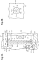
Fig. 2A is an enlarged cross-sectional side view showing the periphery of a first oil supply member. -
Fig. 2B is an enlarged plan view showing the periphery of the first oil supply member. -
Fig. 3A is an enlarged cross-sectional side view showing the periphery of a second oil supply member. -
Fig. 3B is an enlarged plan view showing the periphery of the second oil supply member. -
Fig. 4 is an enlarged plan view showing the periphery of an oil supply member according to another embodiment. -
Fig. 5 is a cross-sectional side view showing part of an electric turbomachine according to a further embodiment. - One embodiment of an electric turbomachine will now be described with reference to
Figs. 1 to 3B . The electric turbomachine in the present embodiment is an electric supercharger mounted in the engine compartment of an automobile and used to compress and supply air as fluid to the engine. - As shown in
Fig. 1 , ahousing 11 of anelectric turbomachine 10 includes atubular motor housing 12 having a closed end. Themotor housing 12 includes a disc-like end wall 12a and acircumferential wall 12b extending from the circumferential edge of the end wall 12a in a tubular manner. Further, thehousing 11 includes a first disc-like seal plate 13 connected to the outer surface of the end wall 12a of themotor housing 12 and a second disc-like seal plate 14 connected to an open end of thecircumferential wall 12b of themotor housing 12. Thehousing 11 also includes acompressor housing 15 connected to the side of thefirst seal plate 13 opposite to themotor housing 12. Themotor housing 12, thefirst seal plate 13, thesecond seal plate 14, and thecompressor housing 15 are made of aluminum. - A first through
hole 12h extends through the end wall 12a of themotor housing 12. A firsttubular bearing case 16 is attached to the first throughhole 12h. Anannular engagement portion 16a protrudes from the inner circumferential surface of the first bearingcase 16. A second throughhole 14h extends through thesecond seal plate 14. A second tubular bearingcase 17 is attached to the second throughhole 14h. Thefirst bearing case 16 and the second bearingcase 17 are made of iron. Thehousing 11 includes acover 18 attached to thesecond seal plate 14. - The
electric turbomachine 10 includes arotary shaft 20 rotationally supported in thehousing 11. Therotary shaft 20 extends from the inside of the second bearingcase 17 into themotor housing 12, passes through thefirst bearing case 16 and thefirst seal plate 13, and then protrudes into thecompressor housing 15. A seal member 13a having a labyrinth seal is located between therotary shaft 20 and thefirst seal plate 13. In the present embodiment, the side of therotary shaft 20 that protrudes into thecompressor housing 15 corresponds to one axial side of therotary shaft 20, namely, the first side. The side of therotary shaft 20 that is adjacent to the second bearingcase 17 corresponds to the other axial side of therotary shaft 20, namely, the second side. An impeller 21 is connected to one axial side of therotary shaft 20, namely, the first side. - A space surrounded by the end wall 12a and the
circumferential wall 12b of themotor housing 12 and thesecond seal plate 14 defines amotor chamber 121. Themotor chamber 121 accommodates anelectric motor 22 that rotates therotary shaft 20. Theelectric motor 22 includes arotor 22a rotated integrally with therotary shaft 20, and astator 22b surrounding therotor 22a.Coils 22c are wound around thestator 22b. Therotary shaft 20 rotates integrally with therotor 22a when thecoils 22c are supplied with current. - The
electric turbomachine 10 includes a first rolling bearing 31 serving as a rolling bearing that rotationally supports a portion of therotary shaft 20 close to the impeller 21 in the axial direction of therotary shaft 20. The first rolling bearing 31 is accommodated in thefirst bearing case 16. - The first rolling bearing 31 is an angular contact ball bearing including a first
inner race 31a serving as an inner race, a firstouter race 31b serving as an outer race, and a plurality offirst balls 31c serving as rolling elements. The firstinner race 31a is fixed to therotary shaft 20. The firstouter race 31b is arranged outward from the firstinner race 31a. Thefirst balls 31c are arranged between the firstinner race 31a and the firstouter race 31b. The firstinner race 31a is press-fitted to therotary shaft 20. The firstouter race 31b is press-fitted to the inner circumferential surface of thefirst bearing case 16. - The
electric turbomachine 10 includes a second rolling bearing 32 serving as a rolling bearing that rotationally supports a portion of therotary shaft 20 further distant from the impeller 21 than the first rolling bearing 31 in the axial direction of therotary shaft 20. Thus, therotary shaft 20 is rotationally supported in thehousing 11 by the first rolling bearing 31 and the second rolling bearing 32. The second rolling bearing 32 is accommodated in thesecond bearing case 17. The second rolling bearing 32 is arranged in thesecond bearing case 17 at an end opposite to thecover 18 in the axial direction of therotary shaft 20. - The second rolling bearing 32 is an angular contact ball bearing including a second
inner race 32a serving as an inner race, a secondouter race 32b serving as an outer race, and a plurality ofsecond balls 32c serving as rolling elements. The secondinner race 32a is fixed to therotary shaft 20. The secondouter race 32b is arranged outward from the secondinner race 32a. Thesecond balls 32c are arranged between the secondinner race 32a and the secondouter race 32b. The secondinner race 32a is press-fitted to therotary shaft 20. The secondouter race 32b is loosely fitted to the inner circumferential surface of thesecond bearing case 17. - The
second bearing case 17 includes anaccommodation chamber 33 between the second rolling bearing 32 and thecover 18 in the axial direction of therotary shaft 20. Theaccommodation chamber 33 accommodates anannular washer 34 and apressurization spring 35. - One end of the
pressurization spring 35 abuts on thecover 18 and the other end of thepressurization spring 35 abuts on an end face of the secondouter race 32b of the second rolling bearing 32 with thewasher 34 located in between. Thepressurization spring 35 is compressed in the axial direction of therotary shaft 20 and arranged between thecover 18 and thewasher 34. Thus, thecover 18 holds thepressurization spring 35. Thepressurization spring 35 biases the second rolling bearing 32 in the axial direction of therotary shaft 20 with the force of thecompressed pressurization spring 35 acting to restore its original shape. - The biasing force of the
pressurization spring 35 is transmitted to the secondouter race 32b via thewasher 34. The biasing force transmitted to the secondouter race 32b is transmitted to the secondinner race 32a via thesecond balls 32c to force the secondinner race 32a toward the impeller 21 in the axial direction of therotary shaft 20. The biasing force of thepressurization spring 35 is transmitted from the secondinner race 32a to therotary shaft 20, and therotary shaft 20 moves toward the impeller 21 in the axial direction of therotary shaft 20. Therotary shaft 20 abuts on the firstinner race 31a of the first rollingbearing 31. Thefirst balls 31c are forced toward the impeller 21 by the firstinner race 31a in the axial direction of therotary shaft 20 and pressed against the firstouter race 31b. The firstouter race 31b abuts on theengagement portion 16a of thefirst bearing case 16 when pressed by thefirst balls 31c. - In the
electric turbomachine 10, when the impeller 21 is rotated, the impeller 21 generates a thrust force that acts to pull therotary shaft 20 from the second rolling bearing 32 toward the first rolling bearing 31 in the axial direction of therotary shaft 20. The first rolling bearing 31 and the second rolling bearing 32 rotationally support therotary shaft 20 while receiving the thrust force via therotary shaft 20. - The
compressor housing 15 includes asuction port 15a, animpeller chamber 15b, adischarge chamber 15c, and adiffuser passage 15d. Thesuction port 15a suctions air (fresh air). Theimpeller chamber 15b is in communication with thesuction port 15a and accommodates the impeller 21. Air compressed by the impeller 21 is discharged into thedischarge chamber 15c. Thediffuser passage 15d connects theimpeller chamber 15b with thedischarge chamber 15c. The impeller 21 rotates when theelectric motor 22 is driven and therotary shaft 20 is rotated. The centrifugal force of the rotating impeller 21 imparts velocity energy to the air suctioned from thesuction port 15a. The air, which is provided with the velocity energy and increased in speed, is decelerated in thediffuser passage 15d arranged at the outlet of the impeller 21. This converts the velocity energy of the air into pressure energy. The air, which has been increased in pressure, is discharged from thedischarge chamber 15c and supplied to the engine (not shown). - Part of the outer circumferential surface of the
circumferential wall 12b of themotor housing 12 includes arecess 12c. Therecess 12c includes aflat bottom surface 12d extending in the axial direction of therotary shaft 20. Thebottom surface 12d of therecess 12c has afirst edge 121d in the axial direction of therotary shaft 20 located at a position overlapping the first rolling bearing 31 in the radial direction of therotary shaft 20. Further, thebottom surface 12d of therecess 12c has asecond edge 122d in the axial direction of therotary shaft 20 located at a position overlapping the second rolling bearing 32 in the radial direction of therotary shaft 20. - A
lid member 36 that closes therecess 12c is attached to the outer circumferential surface of themotor housing 12. Thelid member 36 and therecess 12c define anoil supply unit 37 having empty space supplied with lubricant. Thus, in the present embodiment, thehousing 11 includes theoil supply unit 37 supplied with lubricant. Thelid member 36 has asupply hole 36a for supplying lubricant to theoil supply unit 37. Thesupply hole 36a is supplied with a portion of the engine oil serving as the lubricant. - As shown in
Fig. 2A , thebottom surface 12d of therecess 12c includes afirst positioning recess 38 located toward thefirst edge 121d in the axial direction of therotary shaft 20. Thefirst positioning recess 38 includes abottom surface 38e with afirst insertion hole 41 serving as an insertion hole that extends in the radial direction of therotary shaft 20. Thefirst insertion hole 41 is in communication with theoil supply unit 37 via thefirst positioning recess 38. Thefirst insertion hole 41 has the shape of a circular hole in a plan view and is in communication with themotor chamber 121. - As shown in
Fig. 2B , the inner circumferential surface of thefirst positioning recess 38 has a wider diameter than thefirst insertion hole 41. The inner circumferential surface of thefirst positioning recess 38 partially includes a first straight portion 38a that extends straight. As shown inFig. 2A , in the axial direction of therotary shaft 20, the first straight portion 38a is located on a side of thebottom surface 12d of therecess 12c that faces thefirst edge 121d in the axial direction of therotary shaft 20. - A circular-pipe shaped first
oil supply member 51 is attached to the oil supply unit 37 (motor housing 12). The firstoil supply member 51 extends straight. The firstoil supply member 51 is inserted, from the outer side of theoil supply unit 37, into thefirst insertion hole 41 and protruded into themotor chamber 121 between the end wall 12a of themotor housing 12 and theelectric motor 22 in the axial direction of therotary shaft 20. - The first
oil supply member 51 has an annular first securingportion 51a, which serves as a securing portion, at a first end adjacent to theoil supply unit 37. Thefirst securing portion 51a extends in a direction orthogonal to the axial direction of the firstoil supply member 51. Thefirst securing portion 51a is secured to thebottom surface 38e of thefirst positioning recess 38, which is a wall facing theoil supply unit 37, around thefirst insertion hole 41 in themotor housing 12. Thus, the firstoil supply member 51 is inserted, from the outer side of theoil supply unit 37, into thefirst insertion hole 41. Thefirst securing portion 51a is secured to thebottom surface 38e of thefirst positioning recess 38 around thefirst insertion hole 41 to attach the firstoil supply member 51 to themotor housing 12. As a result, the firstoil supply member 51 is attached to themotor housing 12 such that the firstoil supply member 51 extends in the radial direction of therotary shaft 20. - The first
oil supply member 51 has afirst supply passage 51b serving as a supply passage. Thefirst supply passage 51b extends inside the firstoil supply member 51 in the axial direction in communication with theoil supply unit 37 at a first end of the firstoil supply member 51. Thefirst supply passage 51b has a circular shape in a plan view. Further, the firstoil supply member 51 has afirst ejection hole 51c serving as an ejection hole. Thefirst ejection hole 51c is configured to be in communication with thefirst supply passage 51b and eject lubricant toward a portion between the firstinner race 31a and the firstouter race 31b of the first rollingbearing 31. Thefirst ejection hole 51c is a circular hole. Thefirst supply passage 51b extends in the radial direction of therotary shaft 20, and thefirst supply passage 51b opens in the axial direction of the firstoil supply member 51 at an end face of the first end of the firstoil supply member 51. Thefirst ejection hole 51c extends in the axial direction of therotary shaft 20 and opens in an outer circumferential surface of the firstoil supply member 51 at an end opposite to theoil supply unit 37 in the axial direction. The flow passage cross-sectional area of thefirst ejection hole 51c is smaller than the flow passage cross-sectional area of thefirst supply passage 51b. Specifically, the diameter r1 of thefirst ejection hole 51c is smaller than the diameter r2 of thefirst supply passage 51b. - As shown in
Fig. 2B , the outer circumferential surface of the first securingportion 51a has a first outercircumferential portion 51d that extends straight along the first straight portion 38a of thefirst positioning recess 38. Thefirst securing portion 51a is located in thefirst positioning recess 38, and the first outercircumferential portion 51d contacts the first straight portion 38a. This restricts movement of the firstoil supply member 51 in the circumferential direction. - As shown in
Fig. 2A , the first outercircumferential portion 51d contacts the first straight portion 38a to restrict movement of the firstoil supply member 51 in the circumferential direction. In this state, thefirst ejection hole 51c opens in the outer circumferential surface of the firstoil supply member 51 such that thefirst ejection hole 51c faces a portion between the firstinner race 31a and the firstouter race 31b in the axial direction of therotary shaft 20. The first outercircumferential portion 51d and the first straight portion 38a form a positioning mechanism that positions the firstoil supply member 51 relative to themotor housing 12 such that thefirst ejection hole 51c faces the portion between the firstinner race 31a and the firstouter race 31b. - As shown in
Fig. 3A , thebottom surface 12d of therecess 12c includes asecond positioning recess 39 located toward thesecond edge 122d in the axial direction of therotary shaft 20. Thesecond positioning recess 39 includes abottom surface 39e with asecond insertion hole 42 serving as an insertion hole that extends in the radial direction of therotary shaft 20. Thesecond insertion hole 42 is in communication with theoil supply unit 37 via thesecond positioning recess 39. Thesecond insertion hole 42 has the shape of a circular hole in a plan view and is in communication with themotor chamber 121. - As shown in
Fig. 3B , the inner circumferential surface of thesecond positioning recess 39 has a wider diameter than thesecond insertion hole 42. The inner circumferential surface of thesecond positioning recess 39 partially includes a secondstraight portion 39a that extends straight. As shown inFig. 3A , in the axial direction of therotary shaft 20, the secondstraight portion 39a is located on a side of thebottom surface 12d of therecess 12c that faces thesecond edge 122d in the axial direction of therotary shaft 20. - A second
oil supply member 52 is attached, as a circular-pipe shaped oil supply member, to the oil supply unit 37 (motor housing 12). The secondoil supply member 52 extends straight. The secondoil supply member 52 is inserted, from the outer side of theoil supply unit 37, into thesecond insertion hole 42 and protruded into themotor chamber 121 between thesecond seal plate 14 and theelectric motor 22 in the axial direction of therotary shaft 20. - The second
oil supply member 52 has an annularsecond securing portion 52a, which serves as a securing portion, at a first end adjacent to theoil supply unit 37. Thesecond securing portion 52a extends in a direction orthogonal to the axial direction of the secondoil supply member 52. Thesecond securing portion 52a is secured to thebottom surface 39e of thesecond positioning recess 39, which is a wall facing theoil supply unit 37, around thesecond insertion hole 42 in themotor housing 12. Thus, the secondoil supply member 52 is inserted, from the outer side of theoil supply unit 37, into thesecond insertion hole 42. Thesecond securing portion 52a is secured to thebottom surface 39e of thesecond positioning recess 39 around thesecond insertion hole 42 to attach the secondoil supply member 52 to themotor housing 12. As a result, the secondoil supply member 52 is attached to themotor housing 12 such that the secondoil supply member 52 extends in the radial direction of therotary shaft 20. - The second
oil supply member 52 has asecond supply passage 52b serving as a supply passage. Thesecond supply passage 52b extends inside the secondoil supply member 52 in the axial direction in communication with theoil supply unit 37 at a first end of the secondoil supply member 52. Further, the secondoil supply member 52 has asecond ejection hole 52c serving as an ejection hole. Thesecond ejection hole 52c is configured to be in communication with thesecond supply passage 52b and eject lubricant toward a portion between the secondinner race 32a and the secondouter race 32b of the second rolling bearing 32. Thesecond ejection hole 52c is a circular hole. Thesecond supply passage 52b extends in the radial direction of therotary shaft 20, and thesecond supply passage 52b opens in the axial direction of the secondoil supply member 52 at an end face of the first end of the secondoil supply member 52. Thesecond ejection hole 52c extends in the axial direction of therotary shaft 20 and opens in an outer circumferential surface of the secondoil supply member 52 at an end opposite to theoil supply unit 37 in the axial direction. The flow passage cross-sectional area of thesecond ejection hole 52c is smaller than the flow passage cross-sectional area of thesecond supply passage 52b. Specifically, the diameter r3 of thesecond ejection hole 52c is smaller than the diameter r4 of thesecond supply passage 52b. - As shown in
Fig. 3B , the outer circumferential surface of thesecond securing portion 52a has a second outercircumferential portion 52d that extends straight along the secondstraight portion 39a of thesecond positioning recess 39. Thesecond securing portion 52a is located in thesecond positioning recess 39 and the second outercircumferential portion 52d contacts the secondstraight portion 39a. This restricts movement of the secondoil supply member 52 in the circumferential direction. - As shown in
Fig. 3A , the second outercircumferential portion 52d contacts the secondstraight portion 39a to restrict movement of the secondoil supply member 52 in the circumferential direction. In this state, thesecond ejection hole 52c opens in the outer circumferential surface of the secondoil supply member 52 such that thesecond ejection hole 52c faces a portion between the secondinner race 32a and the secondouter race 32b in the axial direction of therotary shaft 20. The second outercircumferential portion 52d and the secondstraight portion 39a form a positioning mechanism that positions the secondoil supply member 52 relative to themotor housing 12 such that thesecond ejection hole 52c faces the portion between the secondinner race 32a and the secondouter race 32b. - The operation of the present embodiment will now be described.
- Lubricant supplied from the
supply hole 36a to theoil supply unit 37 flows into thefirst supply passage 51b of the firstoil supply member 51 and thesecond supply passage 52b of the secondoil supply member 52. The lubricant, which has entered thefirst supply passage 51b and thesecond supply passage 52b, passes through thefirst supply passage 51b and thesecond supply passage 52b. - The lubricant, which has passed through the
first supply passage 51b, is ejected from thefirst ejection hole 51c toward the portion between the firstinner race 31a and the firstouter race 31b. In this case, the flow passage cross-sectional area of thefirst ejection hole 51c is smaller than the flow passage cross-sectional area of thefirst supply passage 51b. Thus, the lubricant is constricted when passing through thefirst ejection hole 51c and forcefully ejected from thefirst ejection hole 51c toward the portion between the firstinner race 31a and the firstouter race 31b. In this manner, the lubricant is efficiently supplied to the portion between the firstinner race 31a and the firstouter race 31b to improve the slidability between the firstouter race 31b and thefirst balls 31c and the slidability between the firstinner race 31a and thefirst balls 31c. - The lubricant, which has passed through the
second supply passage 52b, is ejected from thesecond ejection hole 52c toward the portion between the secondinner race 32a and the secondouter race 32b. In this case, the flow passage cross-sectional area of thesecond ejection hole 52c is smaller than the flow passage cross-sectional area of thesecond supply passage 52b. Thus, the lubricant is constricted when passing through thesecond ejection hole 52c and forcefully ejected from thesecond ejection hole 52c toward the portion between the secondinner race 32a and the secondouter race 32b. In this manner, the lubricant is efficiently supplied to the portion between the secondinner race 32a and the secondouter race 32b to improve the slidability between the secondouter race 32b and thesecond balls 32c and the slidability between the secondinner race 32a and thesecond balls 32c. - The above embodiment provides the following advantages.
- (1) The first
oil supply member 51 and the secondoil supply member 52 are attached to themotor housing 12. The firstoil supply member 51 includes thefirst supply passage 51b and thefirst ejection hole 51c. Thefirst supply passage 51b extends inside the firstoil supply member 51 in the axial direction in communication with theoil supply unit 37. Thefirst ejection hole 51c is configured to be in communication with thefirst supply passage 51b and eject lubricant toward the portion between the firstinner race 31a and the firstouter race 31b.
The secondoil supply member 52 includes thesecond supply passage 52b and thesecond ejection hole 52c. Thesecond supply passage 52b extends inside the secondoil supply member 52 in the axial direction in communication with theoil supply unit 37. Thesecond ejection hole 52c is configured to be in communication with thesecond supply passage 52b and eject lubricant toward the portion between the secondinner race 32a and the secondouter race 32b.
With this structure, the lubricant from theoil supply unit 37 is ejected from thefirst ejection hole 51c via thefirst supply passage 51b toward the portion between the firstinner race 31a and the firstouter race 31b. Further, the lubricant is ejected from thesecond ejection hole 52c via thesecond supply passage 52b toward the portion between the secondinner race 32a and the secondouter race 32b.
For example, after the lubricant is supplied to the outer circumferential surface of the firstouter race 31b, the lubricant supplied to the outer circumferential surface of the firstouter race 31b may flow into the portion between the firstinner race 31a and the firstouter race 31b. Alternatively, after the lubricant is supplied to the outer circumferential surface of the secondouter race 32b, the lubricant supplied to the outer circumferential surface of the secondouter race 32b may flow into the portion between the secondinner race 32a and the secondouter race 32b. In comparison with such cases, the lubricant is efficiently supplied to the portion between the firstinner race 31a and the firstouter race 31b and to the portion between the secondinner race 32a and the secondouter race 32b. - (2) The flow passage cross-sectional areas of the
first ejection hole 51c and thesecond ejection hole 52c are smaller than the flow passage cross-sectional areas of thefirst supply passage 51b and thesecond supply passage 52b. With this structure, the lubricant from theoil supply unit 37 flows into thefirst supply passage 51b and thesecond supply passage 52b and is constricted when passing through thefirst ejection hole 51c and thesecond ejection hole 52c to be forcefully ejected from thefirst ejection hole 51c and thesecond ejection hole 52c toward the portion between the firstinner race 31a and the firstouter race 31b and the portion between the secondinner race 32a and the secondouter race 32b. As a result, the lubricant is supplied with improved efficiency to the portion between the firstinner race 31a and the firstouter race 31b and the portion between the secondinner race 32a and the secondouter race 32b. - (3) The first
oil supply member 51 has the first securingportion 51a secured to themotor housing 12. The secondoil supply member 52 has thesecond securing portion 52a secured to themotor housing 12. With this structure, the firstoil supply member 51 is attached to themotor housing 12 by merely inserting the firstoil supply member 51 into thefirst insertion hole 41 and securing the first securingportion 51a to themotor housing 12. The secondoil supply member 52 is likewise attached to themotor housing 12 by merely inserting the secondoil supply member 52 into thesecond insertion hole 42 and securing thesecond securing portion 52a to themotor housing 12. - (4) The first outer
circumferential portion 51d and the first straight portion 38a form a positioning mechanism that positions the firstoil supply member 51 relative to themotor housing 12 such that thefirst ejection hole 51c faces the portion between the firstinner race 31a and the firstouter race 31b. The second outercircumferential portion 52d and the secondstraight portion 39a form a positioning mechanism that positions the secondoil supply member 52 relative to themotor housing 12 such that thesecond ejection hole 52c faces the portion between the secondinner race 32a and the secondouter race 32b.
With this structure, the firstoil supply member 51 is attached to themotor housing 12 with the first outercircumferential portion 51d and the first straight portion 38a in a state where the firstoil supply member 51 is positioned relative to themotor housing 12 such that thefirst ejection hole 51c faces the portion between the firstinner race 31a and the firstouter race 31b. This allows the lubricant ejected from thefirst ejection hole 51c to be more readily supplied to the portion between the firstinner race 31a and the firstouter race 31b. Further, the secondoil supply member 52 is attached to themotor housing 12 with the second outercircumferential portion 52d and the secondstraight portion 39a in a state where the secondoil supply member 52 is positioned relative to themotor housing 12 such that thesecond ejection hole 52c faces the portion between the secondinner race 32a and the secondouter race 32b. This allows the lubricant ejected from thesecond ejection hole 52c to be more readily supplied to the portion between the secondinner race 32a and the secondouter race 32b. - (5) The present embodiment eliminates the need to attach a guide member, which guides lubricant toward the portion between the first
inner race 31a and the firstouter race 31b, to an end face facing themotor chamber 121 in thefirst bearing case 16. Further, the present embodiment also eliminates the need to attach a guide member, which guides lubricant toward the portion between the secondinner race 32a and the secondouter race 32b, to an end face facing themotor chamber 121 in thesecond bearing case 17. This simplifies the structure of theelectric turbomachine 10. - The above embodiment may be modified as follows.
- As shown in
Fig. 4 , the inner circumferential surface of thefirst positioning recess 38 may partially include aprotrusion 38f that protrudes inwardly in thefirst positioning recess 38. The outer circumferential surface of the first securingportion 51a may include arecess 51f configured to be secured to theprotrusion 38f.
Movement of the firstoil supply member 51 in the circumferential direction may be restricted when theprotrusion 38f is secured to therecess 51f. The movement of the firstoil supply member 51 in the circumferential direction is restricted when theprotrusion 38f is secured to therecess 51f. In this state, thefirst ejection hole 51c opens in the outer circumferential surface of the firstoil supply member 51 such that thefirst ejection hole 51c faces the portion between the firstinner race 31a and the firstouter race 31b in the axial direction of therotary shaft 20. In this manner, theprotrusion 38f and therecess 51f may form a positioning mechanism that positions the firstoil supply member 51 relative to themotor housing 12 such that thefirst ejection hole 51c faces the portion between the firstinner race 31a and the firstouter race 31b.
In addition, the inner circumferential surface of thesecond positioning recess 39 may partially include aprotrusion 39f that protrudes inwardly in thesecond positioning recess 39. The outer circumferential surface of thesecond securing portion 52a may include arecess 52f configured to be secured to theprotrusion 39f. - As shown in
Fig. 5 , the firstoil supply member 51 and the secondoil supply member 52 may be attached to themotor housing 12 so as to be inclined relative to the axial direction of therotary shaft 20. Thestator 22b includesannular cutouts rotary shaft 20, toward the inner circumferential surface of thestator 22b from the two end faces in the axial direction of therotary shaft 20. The firstoil supply member 51 and the secondoil supply member 52 extend along thecutouts oil supply unit 37. Axial ends of the firstoil supply member 51 and the secondoil supply member 52 located at sides opposite to theoil supply unit 37 are arranged inside thecutouts rotary shaft 20, the distance between theelectric motor 22 and the first rolling bearing 31 is reduced and the distance between theelectric motor 22 and the second rolling bearing 32 is reduced. This reduces the size of theelectric turbomachine 10 in the axial direction of therotary shaft 20. - In the embodiment, the
first positioning recess 38 and thesecond positioning recess 39 may be omitted from thebottom surface 12d of therecess 12c. In this case, contact portions may project from thebottom surface 12d of therecess 12c and be configured to contact the first outercircumferential portion 51d of the first securingportion 51a and the second outercircumferential portion 52d of thesecond securing portion 52a. Movement of the firstoil supply member 51 and the secondoil supply member 52 in the circumferential direction may be restricted by arranging the first securingportion 51a and thesecond securing portion 52a on thebottom surface 12d of therecess 12c and having the first outercircumferential portion 51d and the second outercircumferential portion 52d contact the contact portions, which project from thebottom surface 12d of therecess 12c. - In the embodiment, the
first ejection hole 51c may open in an end face of the firstoil supply member 51 opposite to theoil supply unit 37 in the axial direction. Likewise, thesecond ejection hole 52c may open in an end face of the secondoil supply member 52 opposite to theoil supply unit 37 in the axial direction. In this case, the firstoil supply member 51 and the secondoil supply member 52 need to be attached to themotor housing 12 inclined relative to the axial direction of therotary shaft 20. Further, thefirst ejection hole 51c needs to face the portion between the firstinner race 31a and the firstouter race 31b, and thesecond ejection hole 52c needs to face the portion between the secondinner race 32a and the secondouter race 32b. - In the embodiment, the first
oil supply member 51 and the secondoil supply member 52 do not need to extend straight and may be, for example, curved or bent to be L-shaped. - In the embodiment, the first outer
circumferential portion 51d of the first securingportion 51a may be omitted. The first straight portion 38a of thefirst positioning recess 38 may be omitted. Likewise, the second outercircumferential portion 52d of thesecond securing portion 52a may be omitted. The secondstraight portion 39a of thesecond positioning recess 39 may be omitted. - In the embodiment, the first
oil supply member 51 and the secondoil supply member 52 may be attached to the inner circumferential surface of thecircumferential wall 12b of themotor housing 12 by a fastening member such as a bolt. - In the embodiment, the flow passage cross-sectional areas of the
first ejection hole 51c and thesecond ejection hole 52c may be the same as the flow passage cross-sectional areas of thefirst supply passage 51b and thesecond supply passage 52b. The flow passage cross-sectional areas of thefirst ejection hole 51c and thesecond ejection hole 52c may be greater than the flow passage cross-sectional areas of thefirst supply passage 51b and thesecond supply passage 52b. - In the embodiment, the first rolling bearing 31 and the second rolling bearing 32 may be, for example, a roller bearing including cylindrical rolling elements.
- In the embodiment, the
electric turbomachine 10 may include a rolling bearing in either the first bearing that rotationally supports a portion of therotary shaft 20, which is close to the impeller 21 in the axial direction of therotary shaft 20, or the second bearing that rotationally supports a portion of therotary shaft 20, which is further distant from the impeller 21 than the first bearing in the axial direction of therotary shaft 20. - In the embodiment, the
electric turbomachine 10 may be used as an electric compressor that configures part of an air conditioner and compresses a refrigerant as a fluid, for example.
Claims (4)
- An electric turbomachine comprising:a housinga rotary shaft rotationally supported in the housing by a rolling bearing;an impeller connected to one side of the rotary shaft in an axial direction; andan electric motor that is accommodated in the housing and rotates the rotary shaft, whereinthe rolling bearing includes an inner race fixed to the rotary shaft, an outer race arranged outward from the inner race, and a rolling element arranged between the inner race and the outer race,the housing includes an oil supply unit supplied with lubricant, wherein a tubular oil supply member is attached to the oil supply unit,the oil supply member includesa supply passage that extends inside the oil supply member in an axial direction of the oil supply member in communication with the oil supply unit at a first end of the oil supply member, andan ejection hole configured to be in communication with the supply passage and eject the lubricant toward a portion between the inner race and the outer race of the rolling bearing.
- The electric turbomachine according to claim 1, wherein a flow passage cross-sectional area of the ejection hole is smaller than a flow passage cross-sectional area of the supply passage.
- The electric turbomachine according to claim 1 or 2, wherein
the oil supply member extends straight,
the housing includes an insertion hole into which the oil supply member is inserted, and
the oil supply member includes a securing portion secured to the housing at the first end. - The electric turbomachine according to any one of claims 1 to 3, comprising a positioning mechanism that positions the oil supply member relative to the housing such that the ejection hole faces a portion between the inner race and the outer race.
Applications Claiming Priority (2)
| Application Number | Priority Date | Filing Date | Title |
|---|---|---|---|
| JP2016102486A JP6269728B2 (en) | 2016-05-23 | 2016-05-23 | Electric turbomachine |
| PCT/JP2017/015156 WO2017203881A1 (en) | 2016-05-23 | 2017-04-13 | Electric turbo-machine |
Publications (3)
| Publication Number | Publication Date |
|---|---|
| EP3467282A1 true EP3467282A1 (en) | 2019-04-10 |
| EP3467282A4 EP3467282A4 (en) | 2019-04-10 |
| EP3467282B1 EP3467282B1 (en) | 2020-05-13 |
Family
ID=60411174
Family Applications (1)
| Application Number | Title | Priority Date | Filing Date |
|---|---|---|---|
| EP17802480.8A Not-in-force EP3467282B1 (en) | 2016-05-23 | 2017-04-13 | Electric turbo-machine |
Country Status (4)
| Country | Link |
|---|---|
| US (1) | US20190288576A1 (en) |
| EP (1) | EP3467282B1 (en) |
| JP (1) | JP6269728B2 (en) |
| WO (1) | WO2017203881A1 (en) |
Families Citing this family (9)
| Publication number | Priority date | Publication date | Assignee | Title |
|---|---|---|---|---|
| JP6794922B2 (en) | 2017-05-12 | 2020-12-02 | 株式会社豊田自動織機 | Electric supercharger |
| JP7087677B2 (en) * | 2018-05-25 | 2022-06-21 | トヨタ自動車株式会社 | motor |
| US10495144B1 (en) * | 2018-05-25 | 2019-12-03 | Borgwarner Inc. | Single-row ball bearing with integrated squeeze-film damper |
| JP2020007931A (en) * | 2018-07-05 | 2020-01-16 | 株式会社豊田自動織機 | Electric turbocharger |
| JP7004175B2 (en) * | 2018-10-02 | 2022-01-21 | 株式会社豊田自動織機 | Electric supercharger |
| JP2020090898A (en) * | 2018-12-03 | 2020-06-11 | 株式会社豊田自動織機 | Electric supercharger |
| US10998792B2 (en) * | 2018-12-21 | 2021-05-04 | Abb Schweiz Ag | Polymeric industrial electrical machine |
| DE102020205860A1 (en) * | 2020-05-11 | 2021-11-11 | Aktiebolaget Skf | Bearing arrangement |
| JP7529609B2 (en) * | 2021-03-31 | 2024-08-06 | 本田技研工業株式会社 | Combined Power System |
Family Cites Families (11)
| Publication number | Priority date | Publication date | Assignee | Title |
|---|---|---|---|---|
| JPS5991425U (en) * | 1982-12-14 | 1984-06-21 | トヨタ自動車株式会社 | Turbocharger bearing oil supply path structure |
| DE3817290A1 (en) * | 1988-05-20 | 1989-11-30 | Leybold Ag | TURBOMOLECULAR PUMP |
| US6032466A (en) * | 1996-07-16 | 2000-03-07 | Turbodyne Systems, Inc. | Motor-assisted turbochargers for internal combustion engines |
| JP4372511B2 (en) * | 2003-10-17 | 2009-11-25 | トヨタ自動車株式会社 | Supercharger with rotating electric machine having a cylindrical member extending between bearings |
| JP2006009685A (en) * | 2004-06-25 | 2006-01-12 | Toyota Motor Corp | Turbocharger |
| TWI315382B (en) * | 2006-12-26 | 2009-10-01 | Ind Tech Res Inst | The rotor mechanism of the centrifugal compressor |
| US20100175377A1 (en) * | 2009-01-12 | 2010-07-15 | Will Hippen | Cooling an electrically controlled turbocharger |
| JP5533318B2 (en) * | 2010-06-17 | 2014-06-25 | 株式会社Ihi | Turbo machine |
| JP5529714B2 (en) * | 2010-11-12 | 2014-06-25 | 三菱重工業株式会社 | Electric supercharger rotating shaft support structure |
| JP6102589B2 (en) * | 2013-07-10 | 2017-03-29 | ダイキン工業株式会社 | Turbo compressor and turbo refrigerator |
| JP2015116113A (en) * | 2013-12-16 | 2015-06-22 | ファナック株式会社 | Motor for turbo blower |
-
2016
- 2016-05-23 JP JP2016102486A patent/JP6269728B2/en not_active Expired - Fee Related
-
2017
- 2017-04-13 US US16/301,535 patent/US20190288576A1/en not_active Abandoned
- 2017-04-13 WO PCT/JP2017/015156 patent/WO2017203881A1/en not_active Ceased
- 2017-04-13 EP EP17802480.8A patent/EP3467282B1/en not_active Not-in-force
Also Published As
| Publication number | Publication date |
|---|---|
| EP3467282A4 (en) | 2019-04-10 |
| JP6269728B2 (en) | 2018-01-31 |
| EP3467282B1 (en) | 2020-05-13 |
| US20190288576A1 (en) | 2019-09-19 |
| JP2017210879A (en) | 2017-11-30 |
| WO2017203881A1 (en) | 2017-11-30 |
Similar Documents
| Publication | Publication Date | Title |
|---|---|---|
| EP3467282B1 (en) | Electric turbo-machine | |
| EP2235423B1 (en) | Oil pump for a refrigeration compressor | |
| US20200123968A1 (en) | Electric supercharger | |
| US11624364B2 (en) | Electric compressor | |
| US10294995B2 (en) | Oil seal structure and turbocharger | |
| US10400824B2 (en) | Oil seal structure and turbocharger | |
| EP3486490B1 (en) | Motor-integrated fluid machine | |
| JPWO2017057482A1 (en) | Centrifugal compressor | |
| CN117597855A (en) | Coolant supply system for electric motors | |
| JP2005171860A (en) | Compressor | |
| US7854601B2 (en) | Lubricant-tight vane rotary vacuum pump | |
| US20160160861A1 (en) | Scroll compressor | |
| EP3390828B1 (en) | Oil return with non-circular tube | |
| EP2034187A1 (en) | Compressor | |
| US10816000B2 (en) | Compressor having centrifugation structure for supplying oil | |
| RU2563651C1 (en) | Compressor | |
| US4502854A (en) | Vane compressor having rearwardly located suction connector and discharge connector | |
| EP3128150B1 (en) | Electrically driven supercharger, and supercharging system | |
| CN211737452U (en) | Compressor with a compressor housing having a plurality of compressor blades | |
| CN100408856C (en) | hermetic compressor | |
| CN109386467B (en) | Oil separation device and horizontal compressor | |
| US12018685B2 (en) | Scroll compressor provided with an hydrostatic lower bearing arrangement | |
| WO2023228760A1 (en) | Centrifugal compressor | |
| JP2020070751A (en) | Electric supercharger | |
| CN117514773A (en) | Scroll for scroll compressor and scroll compressor |
Legal Events
| Date | Code | Title | Description |
|---|---|---|---|
| STAA | Information on the status of an ep patent application or granted ep patent |
Free format text: STATUS: THE INTERNATIONAL PUBLICATION HAS BEEN MADE |
|
| PUAI | Public reference made under article 153(3) epc to a published international application that has entered the european phase |
Free format text: ORIGINAL CODE: 0009012 |
|
| STAA | Information on the status of an ep patent application or granted ep patent |
Free format text: STATUS: REQUEST FOR EXAMINATION WAS MADE |
|
| 17P | Request for examination filed |
Effective date: 20181113 |
|
| A4 | Supplementary search report drawn up and despatched |
Effective date: 20190213 |
|
| AK | Designated contracting states |
Kind code of ref document: A1 Designated state(s): AL AT BE BG CH CY CZ DE DK EE ES FI FR GB GR HR HU IE IS IT LI LT LU LV MC MK MT NL NO PL PT RO RS SE SI SK SM TR |
|
| AX | Request for extension of the european patent |
Extension state: BA ME |
|
| DAV | Request for validation of the european patent (deleted) | ||
| DAX | Request for extension of the european patent (deleted) | ||
| RIC1 | Information provided on ipc code assigned before grant |
Ipc: F16C 35/06 20060101ALN20191010BHEP Ipc: F02B 39/14 20060101AFI20191010BHEP Ipc: F02B 39/00 20060101ALI20191010BHEP Ipc: F02B 33/40 20060101ALI20191010BHEP Ipc: F02B 39/10 20060101ALN20191010BHEP Ipc: H02K 1/28 20060101ALN20191010BHEP |
|
| GRAP | Despatch of communication of intention to grant a patent |
Free format text: ORIGINAL CODE: EPIDOSNIGR1 |
|
| STAA | Information on the status of an ep patent application or granted ep patent |
Free format text: STATUS: GRANT OF PATENT IS INTENDED |
|
| INTG | Intention to grant announced |
Effective date: 20191129 |
|
| GRAS | Grant fee paid |
Free format text: ORIGINAL CODE: EPIDOSNIGR3 |
|
| GRAA | (expected) grant |
Free format text: ORIGINAL CODE: 0009210 |
|
| STAA | Information on the status of an ep patent application or granted ep patent |
Free format text: STATUS: THE PATENT HAS BEEN GRANTED |
|
| AK | Designated contracting states |
Kind code of ref document: B1 Designated state(s): AL AT BE BG CH CY CZ DE DK EE ES FI FR GB GR HR HU IE IS IT LI LT LU LV MC MK MT NL NO PL PT RO RS SE SI SK SM TR |
|
| REG | Reference to a national code |
Ref country code: GB Ref legal event code: FG4D |
|
| REG | Reference to a national code |
Ref country code: CH Ref legal event code: EP |
|
| REG | Reference to a national code |
Ref country code: DE Ref legal event code: R096 Ref document number: 602017016825 Country of ref document: DE |
|
| REG | Reference to a national code |
Ref country code: AT Ref legal event code: REF Ref document number: 1270583 Country of ref document: AT Kind code of ref document: T Effective date: 20200615 |
|
| REG | Reference to a national code |
Ref country code: LT Ref legal event code: MG4D |
|
| REG | Reference to a national code |
Ref country code: NL Ref legal event code: MP Effective date: 20200513 |
|
| PG25 | Lapsed in a contracting state [announced via postgrant information from national office to epo] |
Ref country code: NO Free format text: LAPSE BECAUSE OF FAILURE TO SUBMIT A TRANSLATION OF THE DESCRIPTION OR TO PAY THE FEE WITHIN THE PRESCRIBED TIME-LIMIT Effective date: 20200813 Ref country code: FI Free format text: LAPSE BECAUSE OF FAILURE TO SUBMIT A TRANSLATION OF THE DESCRIPTION OR TO PAY THE FEE WITHIN THE PRESCRIBED TIME-LIMIT Effective date: 20200513 Ref country code: GR Free format text: LAPSE BECAUSE OF FAILURE TO SUBMIT A TRANSLATION OF THE DESCRIPTION OR TO PAY THE FEE WITHIN THE PRESCRIBED TIME-LIMIT Effective date: 20200814 Ref country code: IS Free format text: LAPSE BECAUSE OF FAILURE TO SUBMIT A TRANSLATION OF THE DESCRIPTION OR TO PAY THE FEE WITHIN THE PRESCRIBED TIME-LIMIT Effective date: 20200913 Ref country code: PT Free format text: LAPSE BECAUSE OF FAILURE TO SUBMIT A TRANSLATION OF THE DESCRIPTION OR TO PAY THE FEE WITHIN THE PRESCRIBED TIME-LIMIT Effective date: 20200914 Ref country code: SE Free format text: LAPSE BECAUSE OF FAILURE TO SUBMIT A TRANSLATION OF THE DESCRIPTION OR TO PAY THE FEE WITHIN THE PRESCRIBED TIME-LIMIT Effective date: 20200513 Ref country code: LT Free format text: LAPSE BECAUSE OF FAILURE TO SUBMIT A TRANSLATION OF THE DESCRIPTION OR TO PAY THE FEE WITHIN THE PRESCRIBED TIME-LIMIT Effective date: 20200513 |
|
| PG25 | Lapsed in a contracting state [announced via postgrant information from national office to epo] |
Ref country code: RS Free format text: LAPSE BECAUSE OF FAILURE TO SUBMIT A TRANSLATION OF THE DESCRIPTION OR TO PAY THE FEE WITHIN THE PRESCRIBED TIME-LIMIT Effective date: 20200513 Ref country code: HR Free format text: LAPSE BECAUSE OF FAILURE TO SUBMIT A TRANSLATION OF THE DESCRIPTION OR TO PAY THE FEE WITHIN THE PRESCRIBED TIME-LIMIT Effective date: 20200513 Ref country code: BG Free format text: LAPSE BECAUSE OF FAILURE TO SUBMIT A TRANSLATION OF THE DESCRIPTION OR TO PAY THE FEE WITHIN THE PRESCRIBED TIME-LIMIT Effective date: 20200813 Ref country code: LV Free format text: LAPSE BECAUSE OF FAILURE TO SUBMIT A TRANSLATION OF THE DESCRIPTION OR TO PAY THE FEE WITHIN THE PRESCRIBED TIME-LIMIT Effective date: 20200513 |
|
| REG | Reference to a national code |
Ref country code: AT Ref legal event code: MK05 Ref document number: 1270583 Country of ref document: AT Kind code of ref document: T Effective date: 20200513 |
|
| PG25 | Lapsed in a contracting state [announced via postgrant information from national office to epo] |
Ref country code: NL Free format text: LAPSE BECAUSE OF FAILURE TO SUBMIT A TRANSLATION OF THE DESCRIPTION OR TO PAY THE FEE WITHIN THE PRESCRIBED TIME-LIMIT Effective date: 20200513 Ref country code: AL Free format text: LAPSE BECAUSE OF FAILURE TO SUBMIT A TRANSLATION OF THE DESCRIPTION OR TO PAY THE FEE WITHIN THE PRESCRIBED TIME-LIMIT Effective date: 20200513 |
|
| PG25 | Lapsed in a contracting state [announced via postgrant information from national office to epo] |
Ref country code: AT Free format text: LAPSE BECAUSE OF FAILURE TO SUBMIT A TRANSLATION OF THE DESCRIPTION OR TO PAY THE FEE WITHIN THE PRESCRIBED TIME-LIMIT Effective date: 20200513 Ref country code: DK Free format text: LAPSE BECAUSE OF FAILURE TO SUBMIT A TRANSLATION OF THE DESCRIPTION OR TO PAY THE FEE WITHIN THE PRESCRIBED TIME-LIMIT Effective date: 20200513 Ref country code: SM Free format text: LAPSE BECAUSE OF FAILURE TO SUBMIT A TRANSLATION OF THE DESCRIPTION OR TO PAY THE FEE WITHIN THE PRESCRIBED TIME-LIMIT Effective date: 20200513 Ref country code: EE Free format text: LAPSE BECAUSE OF FAILURE TO SUBMIT A TRANSLATION OF THE DESCRIPTION OR TO PAY THE FEE WITHIN THE PRESCRIBED TIME-LIMIT Effective date: 20200513 Ref country code: RO Free format text: LAPSE BECAUSE OF FAILURE TO SUBMIT A TRANSLATION OF THE DESCRIPTION OR TO PAY THE FEE WITHIN THE PRESCRIBED TIME-LIMIT Effective date: 20200513 Ref country code: ES Free format text: LAPSE BECAUSE OF FAILURE TO SUBMIT A TRANSLATION OF THE DESCRIPTION OR TO PAY THE FEE WITHIN THE PRESCRIBED TIME-LIMIT Effective date: 20200513 Ref country code: CZ Free format text: LAPSE BECAUSE OF FAILURE TO SUBMIT A TRANSLATION OF THE DESCRIPTION OR TO PAY THE FEE WITHIN THE PRESCRIBED TIME-LIMIT Effective date: 20200513 |
|
| REG | Reference to a national code |
Ref country code: DE Ref legal event code: R097 Ref document number: 602017016825 Country of ref document: DE |
|
| PG25 | Lapsed in a contracting state [announced via postgrant information from national office to epo] |
Ref country code: PL Free format text: LAPSE BECAUSE OF FAILURE TO SUBMIT A TRANSLATION OF THE DESCRIPTION OR TO PAY THE FEE WITHIN THE PRESCRIBED TIME-LIMIT Effective date: 20200513 Ref country code: SK Free format text: LAPSE BECAUSE OF FAILURE TO SUBMIT A TRANSLATION OF THE DESCRIPTION OR TO PAY THE FEE WITHIN THE PRESCRIBED TIME-LIMIT Effective date: 20200513 |
|
| PLBE | No opposition filed within time limit |
Free format text: ORIGINAL CODE: 0009261 |
|
| STAA | Information on the status of an ep patent application or granted ep patent |
Free format text: STATUS: NO OPPOSITION FILED WITHIN TIME LIMIT |
|
| 26N | No opposition filed |
Effective date: 20210216 |
|
| PGFP | Annual fee paid to national office [announced via postgrant information from national office to epo] |
Ref country code: FR Payment date: 20210309 Year of fee payment: 5 Ref country code: IT Payment date: 20210310 Year of fee payment: 5 |
|
| PG25 | Lapsed in a contracting state [announced via postgrant information from national office to epo] |
Ref country code: SI Free format text: LAPSE BECAUSE OF FAILURE TO SUBMIT A TRANSLATION OF THE DESCRIPTION OR TO PAY THE FEE WITHIN THE PRESCRIBED TIME-LIMIT Effective date: 20200513 |
|
| PGFP | Annual fee paid to national office [announced via postgrant information from national office to epo] |
Ref country code: GB Payment date: 20210318 Year of fee payment: 5 |
|
| PGFP | Annual fee paid to national office [announced via postgrant information from national office to epo] |
Ref country code: DE Payment date: 20210316 Year of fee payment: 5 |
|
| PG25 | Lapsed in a contracting state [announced via postgrant information from national office to epo] |
Ref country code: MC Free format text: LAPSE BECAUSE OF FAILURE TO SUBMIT A TRANSLATION OF THE DESCRIPTION OR TO PAY THE FEE WITHIN THE PRESCRIBED TIME-LIMIT Effective date: 20200513 |
|
| PG25 | Lapsed in a contracting state [announced via postgrant information from national office to epo] |
Ref country code: LU Free format text: LAPSE BECAUSE OF NON-PAYMENT OF DUE FEES Effective date: 20210413 |
|
| REG | Reference to a national code |
Ref country code: BE Ref legal event code: MM Effective date: 20210430 |
|
| PG25 | Lapsed in a contracting state [announced via postgrant information from national office to epo] |
Ref country code: LI Free format text: LAPSE BECAUSE OF NON-PAYMENT OF DUE FEES Effective date: 20210430 Ref country code: CH Free format text: LAPSE BECAUSE OF NON-PAYMENT OF DUE FEES Effective date: 20210430 |
|
| PG25 | Lapsed in a contracting state [announced via postgrant information from national office to epo] |
Ref country code: IE Free format text: LAPSE BECAUSE OF NON-PAYMENT OF DUE FEES Effective date: 20210413 |
|
| PG25 | Lapsed in a contracting state [announced via postgrant information from national office to epo] |
Ref country code: BE Free format text: LAPSE BECAUSE OF NON-PAYMENT OF DUE FEES Effective date: 20210430 |
|
| REG | Reference to a national code |
Ref country code: DE Ref legal event code: R119 Ref document number: 602017016825 Country of ref document: DE |
|
| GBPC | Gb: european patent ceased through non-payment of renewal fee |
Effective date: 20220413 |
|
| PG25 | Lapsed in a contracting state [announced via postgrant information from national office to epo] |
Ref country code: GB Free format text: LAPSE BECAUSE OF NON-PAYMENT OF DUE FEES Effective date: 20220413 Ref country code: FR Free format text: LAPSE BECAUSE OF NON-PAYMENT OF DUE FEES Effective date: 20220430 Ref country code: DE Free format text: LAPSE BECAUSE OF NON-PAYMENT OF DUE FEES Effective date: 20221103 |
|
| PG25 | Lapsed in a contracting state [announced via postgrant information from national office to epo] |
Ref country code: IT Free format text: LAPSE BECAUSE OF NON-PAYMENT OF DUE FEES Effective date: 20220413 |
|
| PG25 | Lapsed in a contracting state [announced via postgrant information from national office to epo] |
Ref country code: CY Free format text: LAPSE BECAUSE OF FAILURE TO SUBMIT A TRANSLATION OF THE DESCRIPTION OR TO PAY THE FEE WITHIN THE PRESCRIBED TIME-LIMIT Effective date: 20200513 |
|
| PG25 | Lapsed in a contracting state [announced via postgrant information from national office to epo] |
Ref country code: HU Free format text: LAPSE BECAUSE OF FAILURE TO SUBMIT A TRANSLATION OF THE DESCRIPTION OR TO PAY THE FEE WITHIN THE PRESCRIBED TIME-LIMIT; INVALID AB INITIO Effective date: 20170413 |
|
| PG25 | Lapsed in a contracting state [announced via postgrant information from national office to epo] |
Ref country code: MK Free format text: LAPSE BECAUSE OF FAILURE TO SUBMIT A TRANSLATION OF THE DESCRIPTION OR TO PAY THE FEE WITHIN THE PRESCRIBED TIME-LIMIT Effective date: 20200513 |
|
| PG25 | Lapsed in a contracting state [announced via postgrant information from national office to epo] |
Ref country code: TR Free format text: LAPSE BECAUSE OF FAILURE TO SUBMIT A TRANSLATION OF THE DESCRIPTION OR TO PAY THE FEE WITHIN THE PRESCRIBED TIME-LIMIT Effective date: 20200513 |
|
| PG25 | Lapsed in a contracting state [announced via postgrant information from national office to epo] |
Ref country code: MT Free format text: LAPSE BECAUSE OF FAILURE TO SUBMIT A TRANSLATION OF THE DESCRIPTION OR TO PAY THE FEE WITHIN THE PRESCRIBED TIME-LIMIT Effective date: 20200513 |