EP3467145A2 - Gasverteilung für chemische dampfabscheidung/-infiltration - Google Patents
Gasverteilung für chemische dampfabscheidung/-infiltration Download PDFInfo
- Publication number
- EP3467145A2 EP3467145A2 EP18194913.2A EP18194913A EP3467145A2 EP 3467145 A2 EP3467145 A2 EP 3467145A2 EP 18194913 A EP18194913 A EP 18194913A EP 3467145 A2 EP3467145 A2 EP 3467145A2
- Authority
- EP
- European Patent Office
- Prior art keywords
- distribution plate
- gas distribution
- cavity
- inlet
- internal cavity
- Prior art date
- Legal status (The legal status is an assumption and is not a legal conclusion. Google has not performed a legal analysis and makes no representation as to the accuracy of the status listed.)
- Granted
Links
Images





Classifications
-
- C—CHEMISTRY; METALLURGY
- C23—COATING METALLIC MATERIAL; COATING MATERIAL WITH METALLIC MATERIAL; CHEMICAL SURFACE TREATMENT; DIFFUSION TREATMENT OF METALLIC MATERIAL; COATING BY VACUUM EVAPORATION, BY SPUTTERING, BY ION IMPLANTATION OR BY CHEMICAL VAPOUR DEPOSITION, IN GENERAL; INHIBITING CORROSION OF METALLIC MATERIAL OR INCRUSTATION IN GENERAL
- C23C—COATING METALLIC MATERIAL; COATING MATERIAL WITH METALLIC MATERIAL; SURFACE TREATMENT OF METALLIC MATERIAL BY DIFFUSION INTO THE SURFACE, BY CHEMICAL CONVERSION OR SUBSTITUTION; COATING BY VACUUM EVAPORATION, BY SPUTTERING, BY ION IMPLANTATION OR BY CHEMICAL VAPOUR DEPOSITION, IN GENERAL
- C23C16/00—Chemical coating by decomposition of gaseous compounds, without leaving reaction products of surface material in the coating, i.e. chemical vapour deposition [CVD] processes
- C23C16/04—Coating on selected surface areas, e.g. using masks
- C23C16/045—Coating cavities or hollow spaces, e.g. interior of tubes; Infiltration of porous substrates
-
- C—CHEMISTRY; METALLURGY
- C04—CEMENTS; CONCRETE; ARTIFICIAL STONE; CERAMICS; REFRACTORIES
- C04B—LIME, MAGNESIA; SLAG; CEMENTS; COMPOSITIONS THEREOF, e.g. MORTARS, CONCRETE OR LIKE BUILDING MATERIALS; ARTIFICIAL STONE; CERAMICS; REFRACTORIES; TREATMENT OF NATURAL STONE
- C04B35/00—Shaped ceramic products characterised by their composition; Ceramics compositions; Processing powders of inorganic compounds preparatory to the manufacturing of ceramic products
- C04B35/515—Shaped ceramic products characterised by their composition; Ceramics compositions; Processing powders of inorganic compounds preparatory to the manufacturing of ceramic products based on non-oxide ceramics
-
- C—CHEMISTRY; METALLURGY
- C04—CEMENTS; CONCRETE; ARTIFICIAL STONE; CERAMICS; REFRACTORIES
- C04B—LIME, MAGNESIA; SLAG; CEMENTS; COMPOSITIONS THEREOF, e.g. MORTARS, CONCRETE OR LIKE BUILDING MATERIALS; ARTIFICIAL STONE; CERAMICS; REFRACTORIES; TREATMENT OF NATURAL STONE
- C04B35/00—Shaped ceramic products characterised by their composition; Ceramics compositions; Processing powders of inorganic compounds preparatory to the manufacturing of ceramic products
- C04B35/515—Shaped ceramic products characterised by their composition; Ceramics compositions; Processing powders of inorganic compounds preparatory to the manufacturing of ceramic products based on non-oxide ceramics
- C04B35/56—Shaped ceramic products characterised by their composition; Ceramics compositions; Processing powders of inorganic compounds preparatory to the manufacturing of ceramic products based on non-oxide ceramics based on carbides or oxycarbides
- C04B35/565—Shaped ceramic products characterised by their composition; Ceramics compositions; Processing powders of inorganic compounds preparatory to the manufacturing of ceramic products based on non-oxide ceramics based on carbides or oxycarbides based on silicon carbide
- C04B35/571—Shaped ceramic products characterised by their composition; Ceramics compositions; Processing powders of inorganic compounds preparatory to the manufacturing of ceramic products based on non-oxide ceramics based on carbides or oxycarbides based on silicon carbide obtained from Si-containing polymer precursors or organosilicon monomers
-
- C—CHEMISTRY; METALLURGY
- C04—CEMENTS; CONCRETE; ARTIFICIAL STONE; CERAMICS; REFRACTORIES
- C04B—LIME, MAGNESIA; SLAG; CEMENTS; COMPOSITIONS THEREOF, e.g. MORTARS, CONCRETE OR LIKE BUILDING MATERIALS; ARTIFICIAL STONE; CERAMICS; REFRACTORIES; TREATMENT OF NATURAL STONE
- C04B35/00—Shaped ceramic products characterised by their composition; Ceramics compositions; Processing powders of inorganic compounds preparatory to the manufacturing of ceramic products
- C04B35/622—Forming processes; Processing powders of inorganic compounds preparatory to the manufacturing of ceramic products
- C04B35/626—Preparing or treating the powders individually or as batches ; preparing or treating macroscopic reinforcing agents for ceramic products, e.g. fibres; mechanical aspects section B
- C04B35/628—Coating the powders or the macroscopic reinforcing agents
- C04B35/62844—Coating fibres
- C04B35/62857—Coating fibres with non-oxide ceramics
- C04B35/6286—Carbides
- C04B35/62863—Silicon carbide
-
- C—CHEMISTRY; METALLURGY
- C04—CEMENTS; CONCRETE; ARTIFICIAL STONE; CERAMICS; REFRACTORIES
- C04B—LIME, MAGNESIA; SLAG; CEMENTS; COMPOSITIONS THEREOF, e.g. MORTARS, CONCRETE OR LIKE BUILDING MATERIALS; ARTIFICIAL STONE; CERAMICS; REFRACTORIES; TREATMENT OF NATURAL STONE
- C04B35/00—Shaped ceramic products characterised by their composition; Ceramics compositions; Processing powders of inorganic compounds preparatory to the manufacturing of ceramic products
- C04B35/622—Forming processes; Processing powders of inorganic compounds preparatory to the manufacturing of ceramic products
- C04B35/626—Preparing or treating the powders individually or as batches ; preparing or treating macroscopic reinforcing agents for ceramic products, e.g. fibres; mechanical aspects section B
- C04B35/628—Coating the powders or the macroscopic reinforcing agents
- C04B35/62884—Coating the powders or the macroscopic reinforcing agents by gas phase techniques
-
- C—CHEMISTRY; METALLURGY
- C04—CEMENTS; CONCRETE; ARTIFICIAL STONE; CERAMICS; REFRACTORIES
- C04B—LIME, MAGNESIA; SLAG; CEMENTS; COMPOSITIONS THEREOF, e.g. MORTARS, CONCRETE OR LIKE BUILDING MATERIALS; ARTIFICIAL STONE; CERAMICS; REFRACTORIES; TREATMENT OF NATURAL STONE
- C04B35/00—Shaped ceramic products characterised by their composition; Ceramics compositions; Processing powders of inorganic compounds preparatory to the manufacturing of ceramic products
- C04B35/71—Ceramic products containing macroscopic reinforcing agents
- C04B35/78—Ceramic products containing macroscopic reinforcing agents containing non-metallic materials
- C04B35/80—Fibres, filaments, whiskers, platelets, or the like
-
- C—CHEMISTRY; METALLURGY
- C23—COATING METALLIC MATERIAL; COATING MATERIAL WITH METALLIC MATERIAL; CHEMICAL SURFACE TREATMENT; DIFFUSION TREATMENT OF METALLIC MATERIAL; COATING BY VACUUM EVAPORATION, BY SPUTTERING, BY ION IMPLANTATION OR BY CHEMICAL VAPOUR DEPOSITION, IN GENERAL; INHIBITING CORROSION OF METALLIC MATERIAL OR INCRUSTATION IN GENERAL
- C23C—COATING METALLIC MATERIAL; COATING MATERIAL WITH METALLIC MATERIAL; SURFACE TREATMENT OF METALLIC MATERIAL BY DIFFUSION INTO THE SURFACE, BY CHEMICAL CONVERSION OR SUBSTITUTION; COATING BY VACUUM EVAPORATION, BY SPUTTERING, BY ION IMPLANTATION OR BY CHEMICAL VAPOUR DEPOSITION, IN GENERAL
- C23C16/00—Chemical coating by decomposition of gaseous compounds, without leaving reaction products of surface material in the coating, i.e. chemical vapour deposition [CVD] processes
- C23C16/22—Chemical coating by decomposition of gaseous compounds, without leaving reaction products of surface material in the coating, i.e. chemical vapour deposition [CVD] processes characterised by the deposition of inorganic material, other than metallic material
- C23C16/30—Deposition of compounds, mixtures or solid solutions, e.g. borides, carbides, nitrides
- C23C16/32—Carbides
- C23C16/325—Silicon carbide
-
- C—CHEMISTRY; METALLURGY
- C23—COATING METALLIC MATERIAL; COATING MATERIAL WITH METALLIC MATERIAL; CHEMICAL SURFACE TREATMENT; DIFFUSION TREATMENT OF METALLIC MATERIAL; COATING BY VACUUM EVAPORATION, BY SPUTTERING, BY ION IMPLANTATION OR BY CHEMICAL VAPOUR DEPOSITION, IN GENERAL; INHIBITING CORROSION OF METALLIC MATERIAL OR INCRUSTATION IN GENERAL
- C23C—COATING METALLIC MATERIAL; COATING MATERIAL WITH METALLIC MATERIAL; SURFACE TREATMENT OF METALLIC MATERIAL BY DIFFUSION INTO THE SURFACE, BY CHEMICAL CONVERSION OR SUBSTITUTION; COATING BY VACUUM EVAPORATION, BY SPUTTERING, BY ION IMPLANTATION OR BY CHEMICAL VAPOUR DEPOSITION, IN GENERAL
- C23C16/00—Chemical coating by decomposition of gaseous compounds, without leaving reaction products of surface material in the coating, i.e. chemical vapour deposition [CVD] processes
- C23C16/44—Chemical coating by decomposition of gaseous compounds, without leaving reaction products of surface material in the coating, i.e. chemical vapour deposition [CVD] processes characterised by the method of coating
- C23C16/4401—Means for minimising impurities, e.g. dust, moisture or residual gas, in the reaction chamber
- C23C16/4405—Cleaning of reactor or parts inside the reactor by using reactive gases
-
- C—CHEMISTRY; METALLURGY
- C23—COATING METALLIC MATERIAL; COATING MATERIAL WITH METALLIC MATERIAL; CHEMICAL SURFACE TREATMENT; DIFFUSION TREATMENT OF METALLIC MATERIAL; COATING BY VACUUM EVAPORATION, BY SPUTTERING, BY ION IMPLANTATION OR BY CHEMICAL VAPOUR DEPOSITION, IN GENERAL; INHIBITING CORROSION OF METALLIC MATERIAL OR INCRUSTATION IN GENERAL
- C23C—COATING METALLIC MATERIAL; COATING MATERIAL WITH METALLIC MATERIAL; SURFACE TREATMENT OF METALLIC MATERIAL BY DIFFUSION INTO THE SURFACE, BY CHEMICAL CONVERSION OR SUBSTITUTION; COATING BY VACUUM EVAPORATION, BY SPUTTERING, BY ION IMPLANTATION OR BY CHEMICAL VAPOUR DEPOSITION, IN GENERAL
- C23C16/00—Chemical coating by decomposition of gaseous compounds, without leaving reaction products of surface material in the coating, i.e. chemical vapour deposition [CVD] processes
- C23C16/44—Chemical coating by decomposition of gaseous compounds, without leaving reaction products of surface material in the coating, i.e. chemical vapour deposition [CVD] processes characterised by the method of coating
- C23C16/4412—Details relating to the exhausts, e.g. pumps, filters, scrubbers, particle traps
-
- C—CHEMISTRY; METALLURGY
- C23—COATING METALLIC MATERIAL; COATING MATERIAL WITH METALLIC MATERIAL; CHEMICAL SURFACE TREATMENT; DIFFUSION TREATMENT OF METALLIC MATERIAL; COATING BY VACUUM EVAPORATION, BY SPUTTERING, BY ION IMPLANTATION OR BY CHEMICAL VAPOUR DEPOSITION, IN GENERAL; INHIBITING CORROSION OF METALLIC MATERIAL OR INCRUSTATION IN GENERAL
- C23C—COATING METALLIC MATERIAL; COATING MATERIAL WITH METALLIC MATERIAL; SURFACE TREATMENT OF METALLIC MATERIAL BY DIFFUSION INTO THE SURFACE, BY CHEMICAL CONVERSION OR SUBSTITUTION; COATING BY VACUUM EVAPORATION, BY SPUTTERING, BY ION IMPLANTATION OR BY CHEMICAL VAPOUR DEPOSITION, IN GENERAL
- C23C16/00—Chemical coating by decomposition of gaseous compounds, without leaving reaction products of surface material in the coating, i.e. chemical vapour deposition [CVD] processes
- C23C16/44—Chemical coating by decomposition of gaseous compounds, without leaving reaction products of surface material in the coating, i.e. chemical vapour deposition [CVD] processes characterised by the method of coating
- C23C16/455—Chemical coating by decomposition of gaseous compounds, without leaving reaction products of surface material in the coating, i.e. chemical vapour deposition [CVD] processes characterised by the method of coating characterised by the method used for introducing gases into reaction chamber or for modifying gas flows in reaction chamber
- C23C16/45502—Flow conditions in reaction chamber
-
- C—CHEMISTRY; METALLURGY
- C23—COATING METALLIC MATERIAL; COATING MATERIAL WITH METALLIC MATERIAL; CHEMICAL SURFACE TREATMENT; DIFFUSION TREATMENT OF METALLIC MATERIAL; COATING BY VACUUM EVAPORATION, BY SPUTTERING, BY ION IMPLANTATION OR BY CHEMICAL VAPOUR DEPOSITION, IN GENERAL; INHIBITING CORROSION OF METALLIC MATERIAL OR INCRUSTATION IN GENERAL
- C23C—COATING METALLIC MATERIAL; COATING MATERIAL WITH METALLIC MATERIAL; SURFACE TREATMENT OF METALLIC MATERIAL BY DIFFUSION INTO THE SURFACE, BY CHEMICAL CONVERSION OR SUBSTITUTION; COATING BY VACUUM EVAPORATION, BY SPUTTERING, BY ION IMPLANTATION OR BY CHEMICAL VAPOUR DEPOSITION, IN GENERAL
- C23C16/00—Chemical coating by decomposition of gaseous compounds, without leaving reaction products of surface material in the coating, i.e. chemical vapour deposition [CVD] processes
- C23C16/44—Chemical coating by decomposition of gaseous compounds, without leaving reaction products of surface material in the coating, i.e. chemical vapour deposition [CVD] processes characterised by the method of coating
- C23C16/455—Chemical coating by decomposition of gaseous compounds, without leaving reaction products of surface material in the coating, i.e. chemical vapour deposition [CVD] processes characterised by the method of coating characterised by the method used for introducing gases into reaction chamber or for modifying gas flows in reaction chamber
- C23C16/45563—Gas nozzles
- C23C16/45565—Shower nozzles
-
- C—CHEMISTRY; METALLURGY
- C23—COATING METALLIC MATERIAL; COATING MATERIAL WITH METALLIC MATERIAL; CHEMICAL SURFACE TREATMENT; DIFFUSION TREATMENT OF METALLIC MATERIAL; COATING BY VACUUM EVAPORATION, BY SPUTTERING, BY ION IMPLANTATION OR BY CHEMICAL VAPOUR DEPOSITION, IN GENERAL; INHIBITING CORROSION OF METALLIC MATERIAL OR INCRUSTATION IN GENERAL
- C23C—COATING METALLIC MATERIAL; COATING MATERIAL WITH METALLIC MATERIAL; SURFACE TREATMENT OF METALLIC MATERIAL BY DIFFUSION INTO THE SURFACE, BY CHEMICAL CONVERSION OR SUBSTITUTION; COATING BY VACUUM EVAPORATION, BY SPUTTERING, BY ION IMPLANTATION OR BY CHEMICAL VAPOUR DEPOSITION, IN GENERAL
- C23C16/00—Chemical coating by decomposition of gaseous compounds, without leaving reaction products of surface material in the coating, i.e. chemical vapour deposition [CVD] processes
- C23C16/44—Chemical coating by decomposition of gaseous compounds, without leaving reaction products of surface material in the coating, i.e. chemical vapour deposition [CVD] processes characterised by the method of coating
- C23C16/455—Chemical coating by decomposition of gaseous compounds, without leaving reaction products of surface material in the coating, i.e. chemical vapour deposition [CVD] processes characterised by the method of coating characterised by the method used for introducing gases into reaction chamber or for modifying gas flows in reaction chamber
- C23C16/45563—Gas nozzles
- C23C16/45574—Nozzles for more than one gas
-
- C—CHEMISTRY; METALLURGY
- C04—CEMENTS; CONCRETE; ARTIFICIAL STONE; CERAMICS; REFRACTORIES
- C04B—LIME, MAGNESIA; SLAG; CEMENTS; COMPOSITIONS THEREOF, e.g. MORTARS, CONCRETE OR LIKE BUILDING MATERIALS; ARTIFICIAL STONE; CERAMICS; REFRACTORIES; TREATMENT OF NATURAL STONE
- C04B2235/00—Aspects relating to ceramic starting mixtures or sintered ceramic products
- C04B2235/02—Composition of constituents of the starting material or of secondary phases of the final product
- C04B2235/30—Constituents and secondary phases not being of a fibrous nature
- C04B2235/38—Non-oxide ceramic constituents or additives
- C04B2235/3817—Carbides
- C04B2235/3826—Silicon carbides
-
- C—CHEMISTRY; METALLURGY
- C04—CEMENTS; CONCRETE; ARTIFICIAL STONE; CERAMICS; REFRACTORIES
- C04B—LIME, MAGNESIA; SLAG; CEMENTS; COMPOSITIONS THEREOF, e.g. MORTARS, CONCRETE OR LIKE BUILDING MATERIALS; ARTIFICIAL STONE; CERAMICS; REFRACTORIES; TREATMENT OF NATURAL STONE
- C04B2235/00—Aspects relating to ceramic starting mixtures or sintered ceramic products
- C04B2235/02—Composition of constituents of the starting material or of secondary phases of the final product
- C04B2235/30—Constituents and secondary phases not being of a fibrous nature
- C04B2235/44—Metal salt constituents or additives chosen for the nature of the anions, e.g. hydrides or acetylacetonate
- C04B2235/444—Halide containing anions, e.g. bromide, iodate, chlorite
-
- C—CHEMISTRY; METALLURGY
- C04—CEMENTS; CONCRETE; ARTIFICIAL STONE; CERAMICS; REFRACTORIES
- C04B—LIME, MAGNESIA; SLAG; CEMENTS; COMPOSITIONS THEREOF, e.g. MORTARS, CONCRETE OR LIKE BUILDING MATERIALS; ARTIFICIAL STONE; CERAMICS; REFRACTORIES; TREATMENT OF NATURAL STONE
- C04B2235/00—Aspects relating to ceramic starting mixtures or sintered ceramic products
- C04B2235/02—Composition of constituents of the starting material or of secondary phases of the final product
- C04B2235/30—Constituents and secondary phases not being of a fibrous nature
- C04B2235/48—Organic compounds becoming part of a ceramic after heat treatment, e.g. carbonising phenol resins
- C04B2235/483—Si-containing organic compounds, e.g. silicone resins, (poly)silanes, (poly)siloxanes or (poly)silazanes
-
- C—CHEMISTRY; METALLURGY
- C04—CEMENTS; CONCRETE; ARTIFICIAL STONE; CERAMICS; REFRACTORIES
- C04B—LIME, MAGNESIA; SLAG; CEMENTS; COMPOSITIONS THEREOF, e.g. MORTARS, CONCRETE OR LIKE BUILDING MATERIALS; ARTIFICIAL STONE; CERAMICS; REFRACTORIES; TREATMENT OF NATURAL STONE
- C04B2235/00—Aspects relating to ceramic starting mixtures or sintered ceramic products
- C04B2235/02—Composition of constituents of the starting material or of secondary phases of the final product
- C04B2235/50—Constituents or additives of the starting mixture chosen for their shape or used because of their shape or their physical appearance
- C04B2235/52—Constituents or additives characterised by their shapes
- C04B2235/5208—Fibers
- C04B2235/5216—Inorganic
- C04B2235/524—Non-oxidic, e.g. borides, carbides, silicides or nitrides
- C04B2235/5244—Silicon carbide
-
- C—CHEMISTRY; METALLURGY
- C04—CEMENTS; CONCRETE; ARTIFICIAL STONE; CERAMICS; REFRACTORIES
- C04B—LIME, MAGNESIA; SLAG; CEMENTS; COMPOSITIONS THEREOF, e.g. MORTARS, CONCRETE OR LIKE BUILDING MATERIALS; ARTIFICIAL STONE; CERAMICS; REFRACTORIES; TREATMENT OF NATURAL STONE
- C04B2235/00—Aspects relating to ceramic starting mixtures or sintered ceramic products
- C04B2235/02—Composition of constituents of the starting material or of secondary phases of the final product
- C04B2235/50—Constituents or additives of the starting mixture chosen for their shape or used because of their shape or their physical appearance
- C04B2235/52—Constituents or additives characterised by their shapes
- C04B2235/5208—Fibers
- C04B2235/5216—Inorganic
- C04B2235/524—Non-oxidic, e.g. borides, carbides, silicides or nitrides
- C04B2235/5248—Carbon, e.g. graphite
-
- C—CHEMISTRY; METALLURGY
- C04—CEMENTS; CONCRETE; ARTIFICIAL STONE; CERAMICS; REFRACTORIES
- C04B—LIME, MAGNESIA; SLAG; CEMENTS; COMPOSITIONS THEREOF, e.g. MORTARS, CONCRETE OR LIKE BUILDING MATERIALS; ARTIFICIAL STONE; CERAMICS; REFRACTORIES; TREATMENT OF NATURAL STONE
- C04B2235/00—Aspects relating to ceramic starting mixtures or sintered ceramic products
- C04B2235/60—Aspects relating to the preparation, properties or mechanical treatment of green bodies or pre-forms
- C04B2235/614—Gas infiltration of green bodies or pre-forms
Definitions
- the present disclosure relates to composite manufacturing, and more specifically, to gas distribution devices for chemical vapor deposition/infiltration systems and methods.
- Carbon/carbon (C/C) composites are used in the aerospace industry for aircraft brake heat sink materials, among other applications.
- Silicon carbide (SiC) based ceramic matrix composites (CMCs) have found use as brake materials and other components in automotive and locomotive industries. These composites are typically produced using, for example, chemical vapor infiltration (CVI) or chemical vapor deposition (CVD).
- CVI chemical vapor infiltration
- CVD chemical vapor deposition
- Such processes generally include placing porous preforms into a reactor and introducing a gaseous precursor to form silicon carbide depositions within the pores of the preform.
- the present disclosure provides a gas distribution plate for a chemical vapor deposition/infiltration system.
- the gas distribution plate includes a body having a first side and a second side opposite the first side, according to various embodiments.
- the body may be hollow and may define an internal cavity.
- the gas distribution plate may further include a plurality of pass-through tubes extending through the internal cavity, with each pass-through tube of the plurality of pass-through tubes extending from a first opening defined in the first side of the body to a second opening defined in the second side of the body.
- a reaction gas may be configured to flow through the plurality of pass-through tubes.
- the gas distribution plate may further include a cavity inlet defined in the body and a plurality of cavity outlets defined in the second side of the body.
- a gaseous mitigation agent may be configured to flow into the internal cavity of the body via the cavity inlet and the gaseous mitigation agent is configured to flow out the internal cavity via the plurality of cavity outlets.
- the reaction gas in the plurality of pass-through tubes is isolated from the gaseous mitigation agent in the internal cavity.
- the plurality of cavity outlets are distributed among the second opening of the plurality of pass-through tubes.
- the gas distribution plate further includes a plurality of static mixing features extending from the second side of the gas distribution plate, wherein the plurality of static mixing features facilitates mixing of the gaseous mitigation agent with the reaction gas.
- Each static mixing feature of the plurality of static mixing features may be "T" shaped.
- the body includes a conical distribution feature protruding into the internal cavity from the second side of the body opposite the cavity inlet.
- a footprint of the conical distribution feature on the second side of the body is solid.
- the plurality of cavity outlets and the second opening of the plurality of pass-through tubes are disposed outward of a footprint of the conical distribution feature on the second side of the body.
- the system may include a chamber having an inlet portion and an outlet portion, wherein the inlet portion is configured to house a porous preform.
- the system may also include a first inlet for introducing a gaseous precursor into the inlet portion of the chamber, a gas distribution plate disposed between the inlet portion and the outlet portion of the chamber, and a second inlet for introducing a gaseous mitigation agent into an internal cavity defined in the gas distribution plate.
- the gas distribution plate may facilitate mixing the gaseous mitigation agent with a reaction gas from the inlet portion of the chamber.
- the system may further include an exhaust conduit coupled in fluidic communication with the outlet portion of the chamber.
- the gas distribution plate includes a plurality of pass-through tubes, wherein the gas distribution plate facilitates mixing the gaseous mitigation agent with the reaction gas from the plurality of pass-through tubes.
- the gas distribution plate may be a first gas distribution plate, and the system further may further include a second gas distribution plate.
- the second gas distribution plate may be disposed between the first gas distribution plate and the outlet portion of the chamber.
- the internal cavity may be a first internal cavity and the second gas distribution plate may include defines a second internal cavity, wherein the gaseous mitigation agent is configured to sequentially flow through both the first internal cavity and the second internal cavity before mixing with the reaction gas.
- the second inlet is configured to introduce the gaseous mitigation agent into the first internal cavity via a first cavity inlet.
- the gaseous mitigation agent may be configured to flow from the first internal cavity to the second internal cavity via a plurality of second cavity inlets extending between the first gas distribution plate and the second gas distribution plate.
- the first cavity inlet is a central conduit and the plurality of second cavity inlets are offshoot conduits that are positioned around the central conduit.
- the second gas distribution plate is disposed between the inlet portion of the chamber and the first gas distribution plate.
- the second gas distribution plate may include a second plurality of pass-through tubes, and the second inlet may include a pass-through conduit that extends through the second gas distribution plate and is configured to introduce the gaseous mitigation agent into the internal cavity via a cavity inlet.
- the pass-through conduit is a central conduit and the cavity inlet is one of a plurality of cavity inlets, wherein the plurality of cavity inlets are offshoot conduits that are positioned around the central conduit.
- the method may include introducing a gaseous precursor into an inlet portion of a chamber that is configured to house a porous preform and introducing a gaseous mitigation agent into an internal cavity of a gas distribution plate disposed between the inlet portion and an outlet portion of the chamber that is downstream of the inlet portion of the chamber.
- the gaseous mitigation agent may be configured to mix with a reaction gas downstream of the gas distribution plate.
- the gaseous precursor may include methyltrichlorosilane (MTS) and the gaseous mitigation agent may include hydrogen gas.
- MTS methyltrichlorosilane
- a manufacturing system(s) and associated method(s) for chemical vapor deposition/infiltration processes such as may be utilized in the fabrication of ceramic matrix composite components.
- the disclosed systems and methods generally mitigate the formation and accumulation of harmful/hazardous byproduct deposits. While numerous details are included herein pertaining to aircraft components, such as brake components, the manufacturing system(s) and method(s) disclosed herein can be applied to fabricate other ceramic matrix composite components and to other chemical vapor deposition/infiltration processes.
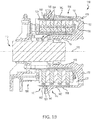
- an aircraft 10 may include landing gear such as left main landing gear 12, right main landing gear 14 and nose landing gear 16.
- Left main landing gear 12, right main landing gear 14, and nose landing gear 16 may generally support aircraft 10 when aircraft 10 is not flying, allowing aircraft 10 to taxi, take off and land without damage.
- Left main landing gear 12 may include wheel 13A and wheel 13B coupled by an axle 20.
- Right main landing gear 14 may include wheel 15A and wheel 15B coupled by an axle 22.
- Nose landing gear 16 may include nose wheel 17A and nose wheel 17B coupled by an axle 24.
- aircraft 10 may comprise any number of landing gears and each landing gear may comprise any number of wheels.
- Left main landing gear 12, right main landing gear 14, and nose landing gear 16 may each be retracted for flight.
- the landing gear may extend from an underside of the fuselage 28 or from an underside of the wings 30.
- the brakes of an aircraft 10 may include a non-rotatable wheel support, a wheel (e.g., wheel 13A, wheel 13B, wheel 15A, wheel 15B, wheel 17A, and/or wheel 17B) mounted to the wheel support for rotation, and a brake disk stack.
- a wheel e.g., wheel 13A, wheel 13B, wheel 15A, wheel 15B, wheel 17A, and/or wheel 17B mounted to the wheel support for rotation
- a brake disk stack e.g., a brake disk stack.
- brake assembly 110 may be found on an aircraft, in accordance with various embodiments.
- Brake assembly 110 may comprise a bogie axle 112, a wheel 114 including a hub 116 and a wheel well 118, a web 120, a torque take-out assembly 122, one or more torque bars 124, a wheel rotational axis 126, a wheel well recess 128, an actuator 130, multiple brake rotors 32, multiple brake stators 34, a pressure plate 36, an end plate 38, a heat shield 140, multiple heat shield sections 142, multiple heat shield carriers 144, an air gap 146, multiple torque bar bolts 148, a torque bar pin 151, a wheel web hole 152, multiple heat shield fasteners 153, multiple rotor lugs 154, and multiple stator slots 156.
- Brake disks e.g., interleaved rotors 32 and stators 34
- Rotors 32 are secured to torque bars 124 for rotation with wheel 114, while stators 34 are engaged with torque take-out assembly 122.
- At least one actuator 130 is operable to compress interleaved rotors 32 and stators 34 for stopping the aircraft.
- actuator 130 is shown as a hydraulically actuated piston.
- Pressure plate 36 and end plate 38 are disposed at opposite ends of the interleaved rotors 32 and stators 34.
- Torque take-out assembly 122 is secured to a stationary portion of the landing gear truck such as a bogie beam or other landing gear strut, such that torque take-out assembly 122 and stators 34 are prevented from rotating during braking of the aircraft.
- Rotors 32 and stators 34 may be fabricated from various materials, such as ceramic matrix composites. The brake disks may withstand and dissipate the heat generated from contact between the brake disks during braking.
- a method 290 of manufacturing a ceramic matrix composite component, such as a brake disk is provided.
- the method 290 may include utilizing the manufacturing apparatus and manufacturing system 305 disclosed herein, as described in greater detail below with reference to FIGS. 3A and 3B .
- the method 290 includes introducing a gaseous precursor into an inlet portion 312 of a chamber 310 at step 292 and introducing a gaseous mitigation agent into an outlet portion 313 of the chamber 310 at step 294, according to various embodiments.
- the inlet portion 312 of the chamber 310 houses one or more porous preforms 315, made from carbon or silicon carbide (SiC) fibers.
- the porous preforms 315 may be loaded into the inlet portion 312 of the chamber 310, which may be a reactor furnace or other reaction compartment.
- the introduction of the gaseous precursor at step 292 results in densification of the porous preforms 315 and the introduction of the gaseous mitigation agent at step 294 shifts the reaction equilibrium to disfavor the formation of harmful and/or pyrophoric deposits, which can accumulate in the exhaust conduit 340 that is coupled in fluidic communication to the outlet portion of the chamber 310, as described in greater detail below.
- the gaseous precursor may be introduced via a first inlet 320 into the inlet portion 312 of the chamber 310 and the gaseous mitigation agent may be introduced via a second inlet 330 into the outlet portion 313 of the chamber 310.
- these two steps 292, 294 are performed simultaneously to fabricate ceramic matrix composite components.
- both the gaseous precursor and the gaseous mitigation agent may be flowing into the respective portions 312, 313 of the chamber 310 during fabrication.
- the inlet portion 312 of the chamber 310 is upstream of the outlet portion 313 of the chamber 310.
- the gaseous precursor is introduced via the first inlet 320 at an inlet upstream side 311 of the inlet portion 312 of the chamber 310 and the gaseous mitigation agent is introduced via the second inlet 330 into an outlet upstream side 314 of the outlet portion 313 of the chamber 310.
- the gaseous mitigation agent may not directly interact with the fibrous/porous preforms 315 and thus may not directly affect the reaction chemistry, as described below, in the inlet portion 312 of the chamber 310.
- the gaseous mitigation agent generally conditions the effluent gas flowing from the inlet portion 312 to inhibit and/or mitigate the formation of harmful byproduct deposits in the exhaust piping (e.g., exhaust conduit 340), according to various embodiments.
- the respective flow rates of gaseous precursor and gaseous mitigation agent are different.
- Introducing the gaseous precursor at step 292 is performed at a first flow rate (e.g., a first molar flow rate, which refers to the number of moles per unit time that passes through an area) and introducing the gaseous mitigation agent at step 294 is performed at a second flow rate (e.g., a second molar flow rate).
- the second molar flow rate is between about 50% and about 300% higher than the gaseous precursor flow rate in the first stream.
- the second molar flow rate is between about 100% and about 200% higher than the gaseous precursor flow rate in the first stream.
- the method 290 includes controlling the temperature and pressure within pressurizing the chamber 310 to specific values.
- the method 290 may include heating the chamber 310 to above 1,000 degrees Celsius (1830 degrees Fahrenheit) and may include maintaining the chamber 310 at 10 torr (1.33 kilopascal).
- the gaseous precursor includes, according to various embodiments, one or more reactants/reagents that react within the inlet portion 312 of the chamber 310 and infiltrate the pores of the porous preforms 315 to densify the porous preforms 315.
- the gaseous precursor may include methyltrichlorosilane (MTS), dimethyldichlorosilane or trimethylchlorosilane, among others.
- MTS may decompose in response to being introduced via the first inlet 320 into the inlet portion 312 of the chamber 310 and, via various intermediate reactions, may result in SiC deposits forming inside the pores of the porous preforms 315.
- the gaseous precursor stream may also include hydrogen gas, according to various embodiments.
- the MTS constitutes about 5% of the gaseous precursor stream.
- the gaseous mitigation agent is hydrogen gas.
- the gaseous mitigation agent introduced at step 294 of the method 290 interacts with the effluent from the inlet portion 312 of the chamber 310 (i.e., interacts with the gaseous stream exiting the inlet portion 312 after passing over and through the porous preforms 315).
- the gaseous mitigation agent shifts the reaction equilibrium of the above listed equations to disfavor the formation of harmful and/or pyrophoric deposits in the exhaust conduit 340. That is, the gaseous mitigation agent alters the stoichiometric ratios of the various/intermediate reactions to mitigate the formation of harmful byproducts which can accumulate within the exhaust conduit 340 of the system 305.
- the harmful byproduct deposits that conventionally form in the exhaust conduit are, for example, polychlorosilanes and cyclic carbosilanes that result from the free radicals and double bonded intermediate species produced in the equations above.
- the "extra" hydrogen gas introduced at step 294 into the outlet portion 313 of the chamber 310 may drive production of HCl via Equation (9), and which may shift the reaction equilibrium to disfavor the formation of the free radical and double bond intermediate species formed in Equations (5), (6), and (8).
- the gaseous precursor may be dimethyldichlorosilane or trimethylchlorosilane, among others.
- the gaseous mitigation agent may include water vapor, NH 3 gas, BCl 3 gas, or air, among others.
- the system 305 which may be a chemical vapor deposition/infiltration apparatus, may include a first supply conduit 322 and a second supply conduit 323.
- the first supply conduit 322 may deliver the gaseous precursor from a source to the inlet portion 312 of the chamber 310 via the first inlet 320.
- the second supply conduit 323 may deliver the gaseous mitigation agent from a source to the outlet portion 313 of the chamber 310 via the second inlet 330.
- a first valve 327 may be coupled to the first supply conduit 322 to control flow of the gaseous precursor and a second valve 328 may be coupled to the second supply conduit 323 to control flow of the gaseous mitigation agent.
- the system 305 may also include a purge valve 329 that is configured to control flow of a purge gas, through one or both of the first and second supply conduits 322, 323, into the chamber 310 for purging the chamber after a completed CVD process.
- a purge valve 329 that is configured to control flow of a purge gas, through one or both of the first and second supply conduits 322, 323, into the chamber 310 for purging the chamber after a completed CVD process.
- the second supply conduit 323 may extend into and through the inlet portion 312 of the chamber 310 to deliver the gaseous mitigation agent to the outlet portion 313 of the chamber 310. That is, the second inlet 330 may be an outlet end of the second supply conduit 323. In various embodiments, the second supply conduit 323 extends through the first inlet 320. For example, the second supply conduit 323 may extend into the chamber 310 so as to deliver the gaseous mitigation agent to a central, upstream section of the outlet portion 313 of the chamber 310. In various embodiments, the second inlet 330 is defined and disposed in a side wall of the chamber 310.
- the inlet portion 312 of the chamber 310 of the manufacturing system 305 may include one or more retention spacers 316 for retaining one or of the porous preforms 315.
- the retention spacers 316 may facilitate distributing the porous preforms 315 throughout the inlet portion 312 of the chamber 310.
- the retention spacers 316 may be porous themselves, thus further allowing sufficient infiltration and deposition.
- the chamber 310 may include one or more gas distributors 318 that facilitate the mixing and distribution of the gaseous precursor flowing through the housed porous preforms 315.
- the gas distributors 318 may also function to divide the inlet portion 312 into sub-compartments.
- the outlet portion 313 of the chamber 310 may define a gas mixing space 319 that may house a gas mixing substrate (e.g., a reaction sub-chamber).
- the gas mixing space 319 may facilitate mixing of the effluent gas from the inlet portion 312 with the gaseous mitigation agent introduced into the outlet portion 313 via the second inlet 330.
- the gas mixing space 319 may include a porous substrate.
- the gas mixing space 319 may be loaded with a gas mixing substrate, such as volcanic rock or graphite, among other materials.
- a gas distribution plate 500 may be utilized to facilitate intermixing of the gaseous mitigation agent with the reaction gas that is produced via the densification of the porous preforms (e.g., the reaction gas is the resultant gas from a chemical vapor deposition/infiltration system).
- the mitigation agent generally shifts the reaction equilibrium to disfavor the formation of harmful and/or pyrophoric deposits, which can accumulate in the exhaust conduit 340 that is coupled in fluidic communication to the outlet portion of the chamber 310.
- the gas distribution plate 500 is disposed between the inlet portion 312 and the outlet portion 313 of the chamber 310.
- a chemical vapor deposition/infiltration method 490 such as a method of manufacturing a ceramic matrix composite component, includes introducing a gaseous precursor into the inlet portion 312 of the chamber 310 at step 492 and introducing a gaseous mitigation agent into an internal cavity 514 ( FIGS. 5A and 5B ) of the gas distribution plate 500 at step 494.
- the gaseous mitigation agent is configured to mix with the reaction gas downstream of the gas distribution plate 500, as described in greater detail immediately below.
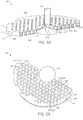
- the gas distribution plate 500 includes a body 510 having a first side 511 and a second side 512 opposite the first side 511.
- the body 510 may have and define an internal cavity 514.
- a plurality of pass-through tubes 520 extend through the internal cavity 514. Said differently, each pass-through tube 520 of the plurality of pass-through tubes extends from a first opening 521 defined in the first side 511 of the body 510 to a second opening 522 defined in the second side 512 of the body 510.
- the reaction gas that results from the chemical vapor deposition/infiltration process in the inlet portion 312 of the chamber 310 is configured to flow through the plurality of pass-through tubes 520, in accordance with various embodiments.
- the gaseous mitigation agent is configured to flow into the internal cavity 514 via a cavity inlet 530, which may be coupled in fluid receiving communication with second inlet 330 ( FIGS. 3A and 3B ).
- the gas distribution plate 500 may further include a plurality of cavity outlets 540 defined in the second side 512 of the body 510 through which the gaseous mitigation agent flows out of the internal cavity 514. Accordingly, the intermixing of the gaseous mitigation agent with the reaction gas is facilitated by distributing the second openings 522 of the plurality of pass-through tubes 520 among the cavity outlets 540.
- the reaction gas configured to flow through the plurality of pass-through tubes 520 is isolated from the gaseous mitigation agent in the internal cavity 514. That is, the reaction gas and the gaseous mitigation agent may not mix within the internal cavity 514, but instead may be configured to mix downstream of the second side 512 of the body 510 of the gas distribution plate 500.
- the body 510 of the gas distribution plate 500 further includes a conical distribution feature 550 that protrudes into the internal cavity 514 from the second side 512 of the body 510 opposite the cavity inlet 530.
- the conical distribution feature 550 may facilitate radially outward flow of the gaseous mitigation agent, thereby promoting distribution of the gaseous mitigation agent through the plurality of cavity outlets 540.
- the body 510 of the gas distribution plate 500 does not have any cavity outlets 540 or pass-through tubes 520 positioned in the footprint of the conical distribution feature 550. That is, the region of the body 510 that falls within the footprint of the conical distribution feature 550 may be solid and may be free of pass-through tubes, openings, apertures, etc.
- the plurality of cavity outlets 540 and the second openings 522 of the plurality of pass-through tubes 520 are disposed outward of the footprint of the conical distribution feature 550 and may be distributed circumferentially around the conical distribution feature 550.
- the gas distribution plate 500 may further include a plurality of static mixing features 560 extending from the second side 512 of the body 510 of the gas distribution plate 500.
- the static mixing features 560 defined herein as non-moving, fixed elements, may be shaped and configured to augment mixing of the gaseous mitigation agent with the reaction gas. Said differently, the plurality of static mixing features facilitates intermixing of the gaseous mitigation agent with the reaction gas.
- the static mixing features 560 may be "T" shaped.
- the static mixing features 560 may extend from the second side 512 of the body 510 of the gas distribution plate 500 adjacent the cavity outlets 540.
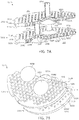
- a dual plate system 50 includes, according to various embodiments, a first gas distribution plate 500A and a second gas distribution plate 500B.
- the dual plate system 50 may be incorporated and utilized with a system of manufacturing a ceramic matrix composite, such as the system of FIGS. 3A and 3B .
- the first gas distribution plate 500A may be upstream of the second gas distribution plate 500B.
- the second gas distribution plate 500B may be disposed between the first gas distribution plate 500A and the outlet portion 313 of the chamber 310.
- the first gas distribution plate 500A may have a first body 510A having a first side 511A and a second side 512A.
- the first body 510A of the first gas distribution plate 500A may define a first internal cavity 514A, and a first plurality of pass-through tubes 520A may extend through the first internal cavity 514A from first openings 521A defined in the first side 511A of the first body 510A to second openings 522A defined in the second side 512A of the first body 510A.
- the second gas distribution plate 500B may have a second body 510B having a first side 511B and a second side 512B.
- the second body 510B of the second gas distribution plate 500B may define a second internal cavity 514B, and a second plurality of pass-through tubes 520B may extend through the second internal cavity 514B from first openings 521B defined in the first side 511B of the second body 510B to second openings 522B defined in the second side 512B of the second body 510B.
- the gaseous mitigation agent may be configured to flow into the internal cavity 514A via cavity inlet 530A (which may be coupled to or a component of second inlet 330).
- the gaseous mitigation agent may be configured to be distributed throughout the internal cavity 514A of the body 510A of the first gas distribution plate 500A.
- the gaseous mitigation agent may instead flow from the internal cavity 514A via a plurality of second cavity inlets 530B that extend between and fluidly couple the first internal cavity 514A of the first body 510A of the first gas distribution plate 500A to a second internal cavity 514B defined in the second body 510B of the second gas distribution plate 500B.
- the first cavity inlet 530A may be a central conduit and the plurality of cavity inlets 530B may be offshoot conduits that are positioned around the central conduit.
- the first body 510A of the first gas distribution plate 500A may not have cavity outlets, such as cavity outlets 540 described above with reference to FIGS. 3A and 3B , defined in the second side 512A of the first body 510A of the first gas distribution plate 500A.
- the gaseous mitigation agent may flow sequentially through both the first internal cavity 514A and the second internal cavity 514B before mixing with the reaction gas.
- the second gas distribution plate 500B may further include a plurality of static mixing features 560 (e.g., described above with reference to FIG. 6 ).
- the dual plate system 60 includes, according to various embodiments, a first gas distribution plate 600A and a second gas distribution plate 600B.
- the dual plate system 60 may be similar to dual plate system 50 described above, and may accordingly be incorporated and utilized with a system of manufacturing a ceramic matrix composite, such as the system of FIGS. 3A and 3B .
- the first gas distribution plate 600A may have a first body 610A having a first side 611A and a second side 612A.
- the first body 610A of the first gas distribution plate 600A may not define an internal cavity (i.e., may not be hollow) and instead may be solid, except for a first plurality of pass-through tubes 620A may extend through the first body 610A from the first side 611A of the first body 610A to the second side 612A of the first body 610A.
- the second gas distribution plate 600B may have a second body 610B having a first side 611B and a second side 612B.
- the second body 610B of the second gas distribution plate 600B may define an internal cavity 614B, and a second plurality of pass-through tubes 620B may extend through the internal cavity 614B from first openings 621B defined in the first side 611B of the second body 610B to second openings 622B defined in the second side 612B of the second body 610B.
- the gaseous mitigation agent may flow through the first gas distribution plate 600A via central pass-through conduit 630A and flows to the internal cavity 614B of the second gas distribution plate 600B via one or more offshoot conduits 630B that are positioned around the central conduit 630A.
- the gaseous mitigation agent is then distributed throughout the internal cavity 614B of the second gas distribution plate 600B and then flows out of the internal cavity 614B via a plurality of cavity outlets 640 to mix with the reaction gas that passed through the two stages of pass-through tubes 620A, 620B.
- the second gas distribution plate 600B may further include a plurality of static mixing features 560 (e.g., described above with reference to FIG. 6 ).
- any of the method or process descriptions may be executed in any order and are not necessarily limited to the order presented.
- any reference to singular includes plural embodiments, and any reference to more than one component or step may include a singular embodiment or step.
- Elements and steps in the figures are illustrated for simplicity and clarity and have not necessarily been rendered according to any particular sequence. For example, steps that may be performed concurrently or in different order are illustrated in the figures to help to improve understanding of embodiments of the present disclosure.
- Any reference to attached, fixed, connected or the like may include permanent, removable, temporary, partial, full and/or any other possible attachment option. Additionally, any reference to without contact (or similar phrases) may also include reduced contact or minimal contact. Surface shading lines may be used throughout the figures to denote different parts or areas but not necessarily to denote the same or different materials. In some cases, reference coordinates may be specific to each figure.
- references to "one embodiment,” “an embodiment,” “various embodiments,” etc. indicate that the embodiment described may include a particular feature, structure, or characteristic, but every embodiment may not necessarily include the particular feature, structure, or characteristic. Moreover, such phrases are not necessarily referring to the same embodiment. Further, when a particular feature, structure, or characteristic is described in connection with an embodiment, it is submitted that it is within the knowledge of one skilled in the art to affect such feature, structure, or characteristic in connection with other embodiments whether or not explicitly described. After reading the description, it will be apparent to one skilled in the relevant art(s) how to implement the disclosure in alternative embodiments.
Landscapes
- Chemical & Material Sciences (AREA)
- Engineering & Computer Science (AREA)
- Organic Chemistry (AREA)
- Materials Engineering (AREA)
- Chemical Kinetics & Catalysis (AREA)
- Metallurgy (AREA)
- Mechanical Engineering (AREA)
- General Chemical & Material Sciences (AREA)
- Ceramic Engineering (AREA)
- Manufacturing & Machinery (AREA)
- Structural Engineering (AREA)
- Inorganic Chemistry (AREA)
- Chemical Vapour Deposition (AREA)
Priority Applications (1)
| Application Number | Priority Date | Filing Date | Title |
|---|---|---|---|
| EP21206030.5A EP3988685A1 (de) | 2017-09-19 | 2018-09-17 | Gasverteilung für chemische dampfabscheidung/-infiltration |
Applications Claiming Priority (1)
| Application Number | Priority Date | Filing Date | Title |
|---|---|---|---|
| US15/709,338 US10480065B2 (en) | 2017-09-19 | 2017-09-19 | Gas distribution for chemical vapor deposition/infiltration |
Related Child Applications (1)
| Application Number | Title | Priority Date | Filing Date |
|---|---|---|---|
| EP21206030.5A Division EP3988685A1 (de) | 2017-09-19 | 2018-09-17 | Gasverteilung für chemische dampfabscheidung/-infiltration |
Publications (3)
| Publication Number | Publication Date |
|---|---|
| EP3467145A2 true EP3467145A2 (de) | 2019-04-10 |
| EP3467145A3 EP3467145A3 (de) | 2019-06-26 |
| EP3467145B1 EP3467145B1 (de) | 2021-11-17 |
Family
ID=63637796
Family Applications (2)
| Application Number | Title | Priority Date | Filing Date |
|---|---|---|---|
| EP18194913.2A Active EP3467145B1 (de) | 2017-09-19 | 2018-09-17 | Gasverteilung für chemische dampfabscheidung/-infiltration |
| EP21206030.5A Pending EP3988685A1 (de) | 2017-09-19 | 2018-09-17 | Gasverteilung für chemische dampfabscheidung/-infiltration |
Family Applications After (1)
| Application Number | Title | Priority Date | Filing Date |
|---|---|---|---|
| EP21206030.5A Pending EP3988685A1 (de) | 2017-09-19 | 2018-09-17 | Gasverteilung für chemische dampfabscheidung/-infiltration |
Country Status (2)
| Country | Link |
|---|---|
| US (2) | US10480065B2 (de) |
| EP (2) | EP3467145B1 (de) |
Families Citing this family (3)
| Publication number | Priority date | Publication date | Assignee | Title |
|---|---|---|---|---|
| KR20260046529A (ko) | 2019-08-23 | 2026-04-07 | 램 리써치 코포레이션 | 열 제어된 샹들리에 샤워헤드 |
| CN119980191A (zh) * | 2019-08-28 | 2025-05-13 | 朗姆研究公司 | 金属沉积 |
| CN113293356A (zh) * | 2021-04-09 | 2021-08-24 | 郭李梁 | 一种制备碳碳复合材料的装置 |
Family Cites Families (26)
| Publication number | Priority date | Publication date | Assignee | Title |
|---|---|---|---|---|
| US4340636A (en) | 1980-07-30 | 1982-07-20 | Avco Corporation | Coated stoichiometric silicon carbide |
| JPS5998295A (ja) * | 1982-11-27 | 1984-06-06 | 能美防災工業株式会社 | 半導体工場などにおける警報および制御装置 |
| JPH03257167A (ja) | 1990-03-06 | 1991-11-15 | Hitachi Electron Eng Co Ltd | 常圧バッチ式cvd装置の反応ガスフロー機構 |
| FR2671797B1 (fr) * | 1991-01-18 | 1994-02-25 | Propulsion Ste Europeenne | Procede de densification d'un substrat poreux par une matrice contenant du carbone. |
| US5527747A (en) * | 1991-10-04 | 1996-06-18 | Georgia Tech Research Corporation | Rapid process for the preparation of diamond articles |
| FR2714076B1 (fr) | 1993-12-16 | 1996-03-15 | Europ Propulsion | Procédé de densification de substrats poreux par infiltration chimique en phase vapeur de carbure de silicium. |
| US5609721A (en) | 1994-03-11 | 1997-03-11 | Fujitsu Limited | Semiconductor device manufacturing apparatus and its cleaning method |
| FR2733254B1 (fr) * | 1995-04-18 | 1997-07-18 | Europ Propulsion | Procede d'infiltration chimique en phase vapeur pour la densification de substrats poreux disposes en piles annulaires |
| DE19646094C2 (de) | 1996-11-08 | 1999-03-18 | Sintec Keramik Gmbh | Verfahren zur chemischen Gasphaseninfiltration von refraktären Stoffen, insbesondere Kohlenstoff und Siliziumkarbid, sowie Verwendung des Verfahrens |
| JP4382265B2 (ja) | 2000-07-12 | 2009-12-09 | 日本電気株式会社 | 酸化シリコン膜の形成方法及びその形成装置 |
| US6630029B2 (en) | 2000-12-04 | 2003-10-07 | General Electric Company | Fiber coating method and reactor |
| JP3991315B2 (ja) | 2002-09-17 | 2007-10-17 | キヤノンアネルバ株式会社 | 薄膜形成装置及び方法 |
| JP4285108B2 (ja) * | 2003-06-25 | 2009-06-24 | 東京エレクトロン株式会社 | トラップ装置、処理システム及び不純物除去方法 |
| JP4306403B2 (ja) * | 2003-10-23 | 2009-08-05 | 東京エレクトロン株式会社 | シャワーヘッド構造及びこれを用いた成膜装置 |
| JP4707959B2 (ja) | 2004-02-20 | 2011-06-22 | 日本エー・エス・エム株式会社 | シャワープレート、プラズマ処理装置及びプラズマ処理方法 |
| US7429410B2 (en) * | 2004-09-20 | 2008-09-30 | Applied Materials, Inc. | Diffuser gravity support |
| GB0516695D0 (en) * | 2005-08-15 | 2005-09-21 | Boc Group Plc | Microwave plasma reactor |
| KR100849929B1 (ko) * | 2006-09-16 | 2008-08-26 | 주식회사 피에조닉스 | 반응 기체의 분사 속도를 적극적으로 조절하는 샤워헤드를구비한 화학기상 증착 방법 및 장치 |
| JP5696348B2 (ja) * | 2008-08-09 | 2015-04-08 | 東京エレクトロン株式会社 | 金属回収方法、金属回収装置、排気系及びこれを用いた成膜装置 |
| US7871587B2 (en) * | 2008-12-23 | 2011-01-18 | Mks Instruments, Inc. | Reactive chemical containment system |
| EP2934732A1 (de) * | 2012-12-18 | 2015-10-28 | Invista Technologies S.à.r.l. | Verfahren zur herstellung von blausäure mit statischem mischer |
| JP6249815B2 (ja) | 2014-02-17 | 2017-12-20 | 株式会社Ihi | 耐熱複合材料の製造方法及び製造装置 |
| WO2015129772A1 (ja) | 2014-02-25 | 2015-09-03 | 株式会社Ihi | 耐熱複合材料の製造方法及び製造装置 |
| DE102015101462A1 (de) | 2015-02-02 | 2016-08-04 | Aixtron Se | Verfahren und Vorrichtung zum Abscheiden einer III-V-Halbleiterschicht |
| US20160229758A1 (en) | 2015-02-11 | 2016-08-11 | United Technologies Corporation | Continuous chemical vapor deposition/infiltration coater |
| US9963779B2 (en) * | 2016-02-29 | 2018-05-08 | Goodrich Corporation | Methods for modifying pressure differential in a chemical vapor process |
-
2017
- 2017-09-19 US US15/709,338 patent/US10480065B2/en active Active
-
2018
- 2018-09-17 EP EP18194913.2A patent/EP3467145B1/de active Active
- 2018-09-17 EP EP21206030.5A patent/EP3988685A1/de active Pending
-
2019
- 2019-10-10 US US16/598,843 patent/US10975467B2/en active Active
Non-Patent Citations (1)
| Title |
|---|
| None |
Also Published As
| Publication number | Publication date |
|---|---|
| EP3467145A3 (de) | 2019-06-26 |
| EP3467145B1 (de) | 2021-11-17 |
| US10975467B2 (en) | 2021-04-13 |
| US10480065B2 (en) | 2019-11-19 |
| US20200040447A1 (en) | 2020-02-06 |
| EP3988685A1 (de) | 2022-04-27 |
| US20190085446A1 (en) | 2019-03-21 |
Similar Documents
| Publication | Publication Date | Title |
|---|---|---|
| US10975467B2 (en) | Gas distribution for chemical vapor deposition/infiltration | |
| US11713281B2 (en) | Mitigating pyrophoric deposits during SiC CVI/CVD processes by introducing a mitigation agent into an exhaust conduit downstream of a reaction chamber | |
| EP3712122A1 (de) | Systeme und verfahren für generativ gefertigte keramische verbundstoffe | |
| CN101120116B (zh) | 通过气相化学渗透对薄形多孔基片进行密实的方法以及这种基片的装载设备 | |
| CN103930594B (zh) | 通过定向流动的蒸汽相化学渗透致密化三维多孔基材的装载设备 | |
| EP3650424B1 (de) | Beschleunigte cvi-verdichtung von cmc durch infiltration | |
| US20080199681A1 (en) | Material For a Brake Disc | |
| US20210156440A1 (en) | Brake disc assembly | |
| EP2810710A1 (de) | Siliko-Alumino-Phosphat | |
| US10731252B2 (en) | Apparatus and method for coating specimens | |
| CN104540980A (zh) | 具有高负载容量的化学气相渗透装置 | |
| US11286209B2 (en) | Ceramic matrix composite manufacturing | |
| EP4361031A1 (de) | Hochtemperaturhartlötung von metallen und keramiken auf kohlenstoffsubstraten | |
| Chawla | Carbon fiber/carbon matrix composites | |
| EP3093278B1 (de) | Verfahren zur herstellung einer kohlenstoff-kohlenstoff-verbundkomponente mit antioxidativer beschichtung | |
| JP7102355B2 (ja) | 化学蒸気含浸又は化学蒸着の方法 | |
| GB2444927A (en) | A ventilated brake disc | |
| EP2745935A1 (de) | Wabenstruktur, herstellungsverfahren dafür, abgasreinigungsvorrichtung und silicoaluminophosphatteilchen | |
| US20240417333A1 (en) | Method for covering fiber body | |
| CN100526670C (zh) | 复合材料制品 | |
| US20240279129A1 (en) | High temperature metal carbide coatings | |
| Childers et al. | Chemical Vapor Deposition Methane Pyrolysis Enables Closed-Loop Oxygen Recovery: Path to Flight | |
| US20240140881A1 (en) | High temperature brazing of metals and ceramics to carbon substrates | |
| WO2017062356A1 (en) | Isostatic graphite liner for fluidized bed reactors | |
| CN105856076B (zh) | 一种催化剂载体内孔壁表面打磨方法 |
Legal Events
| Date | Code | Title | Description |
|---|---|---|---|
| PUAI | Public reference made under article 153(3) epc to a published international application that has entered the european phase |
Free format text: ORIGINAL CODE: 0009012 |
|
| STAA | Information on the status of an ep patent application or granted ep patent |
Free format text: STATUS: THE APPLICATION HAS BEEN PUBLISHED |
|
| AK | Designated contracting states |
Kind code of ref document: A2 Designated state(s): AL AT BE BG CH CY CZ DE DK EE ES FI FR GB GR HR HU IE IS IT LI LT LU LV MC MK MT NL NO PL PT RO RS SE SI SK SM TR |
|
| AX | Request for extension of the european patent |
Extension state: BA ME |
|
| PUAL | Search report despatched |
Free format text: ORIGINAL CODE: 0009013 |
|
| AK | Designated contracting states |
Kind code of ref document: A3 Designated state(s): AL AT BE BG CH CY CZ DE DK EE ES FI FR GB GR HR HU IE IS IT LI LT LU LV MC MK MT NL NO PL PT RO RS SE SI SK SM TR |
|
| AX | Request for extension of the european patent |
Extension state: BA ME |
|
| RIC1 | Information provided on ipc code assigned before grant |
Ipc: C23C 16/455 20060101ALI20190517BHEP Ipc: C23C 16/44 20060101ALI20190517BHEP Ipc: C23C 16/32 20060101ALI20190517BHEP Ipc: C23C 16/04 20060101AFI20190517BHEP |
|
| STAA | Information on the status of an ep patent application or granted ep patent |
Free format text: STATUS: REQUEST FOR EXAMINATION WAS MADE |
|
| 17P | Request for examination filed |
Effective date: 20191227 |
|
| RBV | Designated contracting states (corrected) |
Designated state(s): AL AT BE BG CH CY CZ DE DK EE ES FI FR GB GR HR HU IE IS IT LI LT LU LV MC MK MT NL NO PL PT RO RS SE SI SK SM TR |
|
| RIC1 | Information provided on ipc code assigned before grant |
Ipc: C23C 16/04 20060101AFI20210428BHEP Ipc: C23C 16/32 20060101ALI20210428BHEP Ipc: C23C 16/455 20060101ALI20210428BHEP Ipc: C23C 16/44 20060101ALI20210428BHEP Ipc: C04B 35/571 20060101ALI20210428BHEP Ipc: C04B 35/80 20060101ALI20210428BHEP |
|
| GRAP | Despatch of communication of intention to grant a patent |
Free format text: ORIGINAL CODE: EPIDOSNIGR1 |
|
| STAA | Information on the status of an ep patent application or granted ep patent |
Free format text: STATUS: GRANT OF PATENT IS INTENDED |
|
| INTG | Intention to grant announced |
Effective date: 20210610 |
|
| GRAS | Grant fee paid |
Free format text: ORIGINAL CODE: EPIDOSNIGR3 |
|
| GRAA | (expected) grant |
Free format text: ORIGINAL CODE: 0009210 |
|
| STAA | Information on the status of an ep patent application or granted ep patent |
Free format text: STATUS: THE PATENT HAS BEEN GRANTED |
|
| AK | Designated contracting states |
Kind code of ref document: B1 Designated state(s): AL AT BE BG CH CY CZ DE DK EE ES FI FR GB GR HR HU IE IS IT LI LT LU LV MC MK MT NL NO PL PT RO RS SE SI SK SM TR |
|
| REG | Reference to a national code |
Ref country code: GB Ref legal event code: FG4D |
|
| REG | Reference to a national code |
Ref country code: IE Ref legal event code: FG4D |
|
| REG | Reference to a national code |
Ref country code: DE Ref legal event code: R096 Ref document number: 602018026741 Country of ref document: DE |
|
| REG | Reference to a national code |
Ref country code: AT Ref legal event code: REF Ref document number: 1448116 Country of ref document: AT Kind code of ref document: T Effective date: 20211215 |
|
| REG | Reference to a national code |
Ref country code: LT Ref legal event code: MG9D |
|
| REG | Reference to a national code |
Ref country code: NL Ref legal event code: MP Effective date: 20211117 |
|
| REG | Reference to a national code |
Ref country code: AT Ref legal event code: MK05 Ref document number: 1448116 Country of ref document: AT Kind code of ref document: T Effective date: 20211117 |
|
| PG25 | Lapsed in a contracting state [announced via postgrant information from national office to epo] |
Ref country code: RS Free format text: LAPSE BECAUSE OF FAILURE TO SUBMIT A TRANSLATION OF THE DESCRIPTION OR TO PAY THE FEE WITHIN THE PRESCRIBED TIME-LIMIT Effective date: 20211117 Ref country code: LT Free format text: LAPSE BECAUSE OF FAILURE TO SUBMIT A TRANSLATION OF THE DESCRIPTION OR TO PAY THE FEE WITHIN THE PRESCRIBED TIME-LIMIT Effective date: 20211117 Ref country code: FI Free format text: LAPSE BECAUSE OF FAILURE TO SUBMIT A TRANSLATION OF THE DESCRIPTION OR TO PAY THE FEE WITHIN THE PRESCRIBED TIME-LIMIT Effective date: 20211117 Ref country code: BG Free format text: LAPSE BECAUSE OF FAILURE TO SUBMIT A TRANSLATION OF THE DESCRIPTION OR TO PAY THE FEE WITHIN THE PRESCRIBED TIME-LIMIT Effective date: 20220217 Ref country code: AT Free format text: LAPSE BECAUSE OF FAILURE TO SUBMIT A TRANSLATION OF THE DESCRIPTION OR TO PAY THE FEE WITHIN THE PRESCRIBED TIME-LIMIT Effective date: 20211117 |
|
| PG25 | Lapsed in a contracting state [announced via postgrant information from national office to epo] |
Ref country code: IS Free format text: LAPSE BECAUSE OF FAILURE TO SUBMIT A TRANSLATION OF THE DESCRIPTION OR TO PAY THE FEE WITHIN THE PRESCRIBED TIME-LIMIT Effective date: 20220317 Ref country code: SE Free format text: LAPSE BECAUSE OF FAILURE TO SUBMIT A TRANSLATION OF THE DESCRIPTION OR TO PAY THE FEE WITHIN THE PRESCRIBED TIME-LIMIT Effective date: 20211117 Ref country code: PT Free format text: LAPSE BECAUSE OF FAILURE TO SUBMIT A TRANSLATION OF THE DESCRIPTION OR TO PAY THE FEE WITHIN THE PRESCRIBED TIME-LIMIT Effective date: 20220317 Ref country code: PL Free format text: LAPSE BECAUSE OF FAILURE TO SUBMIT A TRANSLATION OF THE DESCRIPTION OR TO PAY THE FEE WITHIN THE PRESCRIBED TIME-LIMIT Effective date: 20211117 Ref country code: NO Free format text: LAPSE BECAUSE OF FAILURE TO SUBMIT A TRANSLATION OF THE DESCRIPTION OR TO PAY THE FEE WITHIN THE PRESCRIBED TIME-LIMIT Effective date: 20220217 Ref country code: NL Free format text: LAPSE BECAUSE OF FAILURE TO SUBMIT A TRANSLATION OF THE DESCRIPTION OR TO PAY THE FEE WITHIN THE PRESCRIBED TIME-LIMIT Effective date: 20211117 Ref country code: LV Free format text: LAPSE BECAUSE OF FAILURE TO SUBMIT A TRANSLATION OF THE DESCRIPTION OR TO PAY THE FEE WITHIN THE PRESCRIBED TIME-LIMIT Effective date: 20211117 Ref country code: HR Free format text: LAPSE BECAUSE OF FAILURE TO SUBMIT A TRANSLATION OF THE DESCRIPTION OR TO PAY THE FEE WITHIN THE PRESCRIBED TIME-LIMIT Effective date: 20211117 Ref country code: GR Free format text: LAPSE BECAUSE OF FAILURE TO SUBMIT A TRANSLATION OF THE DESCRIPTION OR TO PAY THE FEE WITHIN THE PRESCRIBED TIME-LIMIT Effective date: 20220218 Ref country code: ES Free format text: LAPSE BECAUSE OF FAILURE TO SUBMIT A TRANSLATION OF THE DESCRIPTION OR TO PAY THE FEE WITHIN THE PRESCRIBED TIME-LIMIT Effective date: 20211117 |
|
| PG25 | Lapsed in a contracting state [announced via postgrant information from national office to epo] |
Ref country code: SM Free format text: LAPSE BECAUSE OF FAILURE TO SUBMIT A TRANSLATION OF THE DESCRIPTION OR TO PAY THE FEE WITHIN THE PRESCRIBED TIME-LIMIT Effective date: 20211117 Ref country code: SK Free format text: LAPSE BECAUSE OF FAILURE TO SUBMIT A TRANSLATION OF THE DESCRIPTION OR TO PAY THE FEE WITHIN THE PRESCRIBED TIME-LIMIT Effective date: 20211117 Ref country code: RO Free format text: LAPSE BECAUSE OF FAILURE TO SUBMIT A TRANSLATION OF THE DESCRIPTION OR TO PAY THE FEE WITHIN THE PRESCRIBED TIME-LIMIT Effective date: 20211117 Ref country code: EE Free format text: LAPSE BECAUSE OF FAILURE TO SUBMIT A TRANSLATION OF THE DESCRIPTION OR TO PAY THE FEE WITHIN THE PRESCRIBED TIME-LIMIT Effective date: 20211117 Ref country code: DK Free format text: LAPSE BECAUSE OF FAILURE TO SUBMIT A TRANSLATION OF THE DESCRIPTION OR TO PAY THE FEE WITHIN THE PRESCRIBED TIME-LIMIT Effective date: 20211117 Ref country code: CZ Free format text: LAPSE BECAUSE OF FAILURE TO SUBMIT A TRANSLATION OF THE DESCRIPTION OR TO PAY THE FEE WITHIN THE PRESCRIBED TIME-LIMIT Effective date: 20211117 |
|
| REG | Reference to a national code |
Ref country code: DE Ref legal event code: R097 Ref document number: 602018026741 Country of ref document: DE |
|
| PLBE | No opposition filed within time limit |
Free format text: ORIGINAL CODE: 0009261 |
|
| STAA | Information on the status of an ep patent application or granted ep patent |
Free format text: STATUS: NO OPPOSITION FILED WITHIN TIME LIMIT |
|
| 26N | No opposition filed |
Effective date: 20220818 |
|
| PG25 | Lapsed in a contracting state [announced via postgrant information from national office to epo] |
Ref country code: AL Free format text: LAPSE BECAUSE OF FAILURE TO SUBMIT A TRANSLATION OF THE DESCRIPTION OR TO PAY THE FEE WITHIN THE PRESCRIBED TIME-LIMIT Effective date: 20211117 |
|
| PG25 | Lapsed in a contracting state [announced via postgrant information from national office to epo] |
Ref country code: SI Free format text: LAPSE BECAUSE OF FAILURE TO SUBMIT A TRANSLATION OF THE DESCRIPTION OR TO PAY THE FEE WITHIN THE PRESCRIBED TIME-LIMIT Effective date: 20211117 |
|
| REG | Reference to a national code |
Ref country code: DE Ref legal event code: R119 Ref document number: 602018026741 Country of ref document: DE |
|
| PG25 | Lapsed in a contracting state [announced via postgrant information from national office to epo] |
Ref country code: MC Free format text: LAPSE BECAUSE OF FAILURE TO SUBMIT A TRANSLATION OF THE DESCRIPTION OR TO PAY THE FEE WITHIN THE PRESCRIBED TIME-LIMIT Effective date: 20211117 |
|
| REG | Reference to a national code |
Ref country code: CH Ref legal event code: PL |
|
| REG | Reference to a national code |
Ref country code: BE Ref legal event code: MM Effective date: 20220930 |
|
| PG25 | Lapsed in a contracting state [announced via postgrant information from national office to epo] |
Ref country code: IT Free format text: LAPSE BECAUSE OF FAILURE TO SUBMIT A TRANSLATION OF THE DESCRIPTION OR TO PAY THE FEE WITHIN THE PRESCRIBED TIME-LIMIT Effective date: 20211117 |
|
| P01 | Opt-out of the competence of the unified patent court (upc) registered |
Effective date: 20230521 |
|
| PG25 | Lapsed in a contracting state [announced via postgrant information from national office to epo] |
Ref country code: LU Free format text: LAPSE BECAUSE OF NON-PAYMENT OF DUE FEES Effective date: 20220917 |
|
| PG25 | Lapsed in a contracting state [announced via postgrant information from national office to epo] |
Ref country code: LI Free format text: LAPSE BECAUSE OF NON-PAYMENT OF DUE FEES Effective date: 20220930 Ref country code: IE Free format text: LAPSE BECAUSE OF NON-PAYMENT OF DUE FEES Effective date: 20220917 Ref country code: DE Free format text: LAPSE BECAUSE OF NON-PAYMENT OF DUE FEES Effective date: 20230401 Ref country code: CH Free format text: LAPSE BECAUSE OF NON-PAYMENT OF DUE FEES Effective date: 20220930 |
|
| PG25 | Lapsed in a contracting state [announced via postgrant information from national office to epo] |
Ref country code: BE Free format text: LAPSE BECAUSE OF NON-PAYMENT OF DUE FEES Effective date: 20220930 |
|
| PG25 | Lapsed in a contracting state [announced via postgrant information from national office to epo] |
Ref country code: HU Free format text: LAPSE BECAUSE OF FAILURE TO SUBMIT A TRANSLATION OF THE DESCRIPTION OR TO PAY THE FEE WITHIN THE PRESCRIBED TIME-LIMIT; INVALID AB INITIO Effective date: 20180917 |
|
| PG25 | Lapsed in a contracting state [announced via postgrant information from national office to epo] |
Ref country code: CY Free format text: LAPSE BECAUSE OF FAILURE TO SUBMIT A TRANSLATION OF THE DESCRIPTION OR TO PAY THE FEE WITHIN THE PRESCRIBED TIME-LIMIT Effective date: 20211117 |
|
| PG25 | Lapsed in a contracting state [announced via postgrant information from national office to epo] |
Ref country code: MK Free format text: LAPSE BECAUSE OF FAILURE TO SUBMIT A TRANSLATION OF THE DESCRIPTION OR TO PAY THE FEE WITHIN THE PRESCRIBED TIME-LIMIT Effective date: 20211117 |
|
| PG25 | Lapsed in a contracting state [announced via postgrant information from national office to epo] |
Ref country code: MT Free format text: LAPSE BECAUSE OF FAILURE TO SUBMIT A TRANSLATION OF THE DESCRIPTION OR TO PAY THE FEE WITHIN THE PRESCRIBED TIME-LIMIT Effective date: 20211117 |
|
| PGFP | Annual fee paid to national office [announced via postgrant information from national office to epo] |
Ref country code: GB Payment date: 20250820 Year of fee payment: 8 |
|
| PGFP | Annual fee paid to national office [announced via postgrant information from national office to epo] |
Ref country code: FR Payment date: 20250820 Year of fee payment: 8 |
|
| PG25 | Lapsed in a contracting state [announced via postgrant information from national office to epo] |
Ref country code: TR Free format text: LAPSE BECAUSE OF FAILURE TO SUBMIT A TRANSLATION OF THE DESCRIPTION OR TO PAY THE FEE WITHIN THE PRESCRIBED TIME-LIMIT Effective date: 20211117 |