EP3466794A1 - Industrial carriage, in particular for transporting loads on pallet - Google Patents
Industrial carriage, in particular for transporting loads on pallet Download PDFInfo
- Publication number
- EP3466794A1 EP3466794A1 EP17194825.0A EP17194825A EP3466794A1 EP 3466794 A1 EP3466794 A1 EP 3466794A1 EP 17194825 A EP17194825 A EP 17194825A EP 3466794 A1 EP3466794 A1 EP 3466794A1
- Authority
- EP
- European Patent Office
- Prior art keywords
- carriage
- arm
- industrial
- wheel
- respect
- Prior art date
- Legal status (The legal status is an assumption and is not a legal conclusion. Google has not performed a legal analysis and makes no representation as to the accuracy of the status listed.)
- Granted
Links
Images


Classifications
-
- B—PERFORMING OPERATIONS; TRANSPORTING
- B62—LAND VEHICLES FOR TRAVELLING OTHERWISE THAN ON RAILS
- B62B—HAND-PROPELLED VEHICLES, e.g. HAND CARTS OR PERAMBULATORS; SLEDGES
- B62B3/00—Hand carts having more than one axis carrying transport wheels; Steering devices therefor; Equipment therefor
- B62B3/04—Hand carts having more than one axis carrying transport wheels; Steering devices therefor; Equipment therefor involving means for grappling or securing in place objects to be carried; Loading or unloading equipment
- B62B3/06—Hand carts having more than one axis carrying transport wheels; Steering devices therefor; Equipment therefor involving means for grappling or securing in place objects to be carried; Loading or unloading equipment for simply clearing the load from the ground
- B62B3/0618—Hand carts having more than one axis carrying transport wheels; Steering devices therefor; Equipment therefor involving means for grappling or securing in place objects to be carried; Loading or unloading equipment for simply clearing the load from the ground using fluid lifting mechanisms
-
- B—PERFORMING OPERATIONS; TRANSPORTING
- B62—LAND VEHICLES FOR TRAVELLING OTHERWISE THAN ON RAILS
- B62B—HAND-PROPELLED VEHICLES, e.g. HAND CARTS OR PERAMBULATORS; SLEDGES
- B62B3/00—Hand carts having more than one axis carrying transport wheels; Steering devices therefor; Equipment therefor
- B62B3/04—Hand carts having more than one axis carrying transport wheels; Steering devices therefor; Equipment therefor involving means for grappling or securing in place objects to be carried; Loading or unloading equipment
- B62B3/06—Hand carts having more than one axis carrying transport wheels; Steering devices therefor; Equipment therefor involving means for grappling or securing in place objects to be carried; Loading or unloading equipment for simply clearing the load from the ground
- B62B3/0612—Hand carts having more than one axis carrying transport wheels; Steering devices therefor; Equipment therefor involving means for grappling or securing in place objects to be carried; Loading or unloading equipment for simply clearing the load from the ground power operated
-
- B—PERFORMING OPERATIONS; TRANSPORTING
- B62—LAND VEHICLES FOR TRAVELLING OTHERWISE THAN ON RAILS
- B62B—HAND-PROPELLED VEHICLES, e.g. HAND CARTS OR PERAMBULATORS; SLEDGES
- B62B2203/00—Grasping, holding, supporting the objects
- B62B2203/20—Grasping, holding, supporting the objects using forks or tines
-
- B—PERFORMING OPERATIONS; TRANSPORTING
- B62—LAND VEHICLES FOR TRAVELLING OTHERWISE THAN ON RAILS
- B62B—HAND-PROPELLED VEHICLES, e.g. HAND CARTS OR PERAMBULATORS; SLEDGES
- B62B2203/00—Grasping, holding, supporting the objects
- B62B2203/20—Grasping, holding, supporting the objects using forks or tines
- B62B2203/26—Grasping, holding, supporting the objects using forks or tines the fork being independent from the supporting arms in which the wheels are incorporated
-
- B—PERFORMING OPERATIONS; TRANSPORTING
- B62—LAND VEHICLES FOR TRAVELLING OTHERWISE THAN ON RAILS
- B62B—HAND-PROPELLED VEHICLES, e.g. HAND CARTS OR PERAMBULATORS; SLEDGES
- B62B5/00—Accessories or details specially adapted for hand carts
- B62B5/0026—Propulsion aids
- B62B5/0033—Electric motors
- B62B5/0036—Arrangements of motors
- B62B5/0043—One motor drives one wheel
Definitions
- the invention refers to an industrial carriage, and in particular refers to an industrial carriage for transporting loads on pallet or for transporting free loads, of various sizes, also with relevant weight, and in particular with unbalanced center of gravity.
- the industrial carriages typically comprise a rudder that controls a wheeled carriage that is pivotally installed on a supporting frame from which departs a fork, provided with two arms, suitable in use to enter inside the pallet itself.
- each arm of the fork is provided with a roller or wheel, positioned in correspondence with an ending portion of the fork itself; the purpose of said roller or wheel is to support the weight of the load, with a wheeled carriage, by avoiding the creation of a huge lever on the fork itself.
- the rudder comprises a function of lifting of the fork that permits in use, when the fork is opportunely introduced in the pallet, to lift the pallet itself, permitting then the displacement.
- the document DE9205223U1 describes an industrial carriage comprising a system for compensating the slope of a ramp.
- the Applicant has in particular observed that for these products or loads, the unbalance given by the load or by the product affects also the transportability of the load or of the product on ramps.
- the purpose of the present invention is then to describe an industrial carriage that permits to solve the above described drawbacks.
- an industrial carriage in particular for the transport of loads on pallet comprising:
- the industrial carriage (1) comprises also a second carriage (3b) installed on said supporting frame (2).
- said at least first carriage (3a) is pivotally installed on said supporting frame (2) and rotates with respect to a second reference axis (X) orthogonal with respect to said first reference axis (Y).
- said first carriage (3a) and said second carriage (3b) are pivotally installed on said supporting frame (2) and rotate with respect to a second reference axis (X) orthogonal with respect to said first reference axis (Y).
- said industrial carriage (1) comprises a system of compensation of load unbalances and/or of compensation of slope, said system of compensation being designed for operating along said first reference axis (Y) and/or along a third reference axis (Z) orthogonal with respect to said first reference axis (Y).
- the third reference axis (Z) is also orthogonal with respect to said second reference axis (X).
- said system of compensation comprises also an actuator for said first carriage (3a), said actuator (19) comprising at least a first operating configuration with a first linear extension, in correspondence of which of said first carriage (3a) is in a first position with respect to said supporting frame and a second operating configuration with a second linear extension, preferably longer than said first linear extension, in correspondence of which said first carriage (3a) is in a second position with respect to said supporting frame (2), said second position being different from said first position.
- said actuator for said first carriage (3a) is a linear actuator.
- said system of compensation comprises at least an actuator (19), preferably linear, for said first carriage (3a), and optionally an actuator, preferably linear, for said second carriage (3b), said actuator (19), preferably linear, being configured for arranging in at least a first operating configuration in correspondence of which said first carriage (3a), and optionally said second carriage (3b) are in a first position with respect to said supporting frame, and in a second operating configuration in correspondence of which said first carriage (3a), and optionally said second carriage (3b), are in a second position with respect to said supporting frame (2), said second position being different from said first position.
- said system of compensation comprises at least an actuator (19), for said first carriage (3a), and an actuator (19) for said second carriage (3b), and wherein each one of said actuators (19) is configured for arranging in at least a first operating configuration in correspondence of which said first carriage (3a) and/or said second carriage (3b) are in a first position with respect to said supporting frame, and in a second operating configuration in correspondence of which said first carriage (3a) and/or said second carriage (3b) are in a second position with respect to said supporting frame (2), said second position being different from said first position,
- said linear actuator for said first carriage and/or second carriage (3a, 3b) is a piston.
- said piston is a hydraulic piston.
- said actuator for said first carriage (3a) is operable independently from said actuator for said second carriage (3b).
- said actuator for said first carriage being operable independently from said actuator for said second carriage.
- said first carriage (3a) comprises a first and a second wheel (10) and at least a first motor (11) connected to said first wheel (10) and/or to said second wheel.
- said first carriage (3a) and said second carriage (3b) comprise each one a first and a second wheel (10) and at least a first motor (11) connected to said first wheel (10) and/or to said second wheel.
- said first carriage (3a) and/or said second carriage (3b) comprise each one a first and a second wheel (10) and a first motor (11) connected to said first wheel (10) and a second motor connected to said second wheel (10).
- said first carriage (3a) and said second carriage (3b) comprise each one a first and a second wheel (10) a first motor (11) connected to said first wheel (10) and a second motor connected to said second wheel (10) wherein said first and said second motor are configured:
- said industrial carriage (1) for each first or second arm (4a, 4b), comprises at least an actuator (6), that in said first operating configuration causes a first extension of said second portion (4d) of the respective arm with respect to said first portion (4c), and in said second operating configuration it causes a second extension of said second portion (4d) of the respective arm with respect to said first portion (4c), said second extension being longer than said first extension, and being in particular a maximal extension.
- said actuator (6) comprises a first ending in use constrained to said first portion (4c) of the respective arm (4a; 4b) and a second ending constrained to said second portion (4d) of the respective arm (4a; 4b).
- said second ending is movable with respect to said first ending.
- said actuator (6) is a linear actuator.
- said actuator (6) is a piston.
- said piston is a hydraulic piston.
- said first arm (4a) and/or said second arm (4b) are carriaged arms equipped with at least a wheel or roller (5) configured for supporting the respective arm with respect to a supporting plan or ground upon which in use the respective arm lies.
- said at least a wheel or roller (5) being idly installed on said arm.
- said at least a wheel or roller is installed in correspondence with said second portion (4d) of said first arm (4a) and of said second arm (4b).
- said system of compensation comprises a movable support for said at least a wheel or roller, said movable support being installed in correspondence with said first arm (4a) and/or said second arm (4b);
- the movable support is configured to permit to said wheel of roller (5) a movement between a first position wherein the axis of said wheel of roller (5) is in a first position with respect to said arm and a second position wherein the axis of said wheel or roller (5) is in a second position with respect to said arm.
- said actuator (13) preferably linear, is installed in correspondence with the second portion (4d) of said first and/or second arm (4a; 4b), said actuator (13) being configured for operating during the movement said movable support (14) of the wheel or roller (5) at least between said first and second position.
- said industrial carriage (1) comprises also a system of transversal movement for said first and second arm (4a, 4b), configured for permitting to vary the positioning of the first and second arm (4a, 4b) at least between a first reciprocal distance and a second reciprocal distance.
- the system of transversal movement comprises at least a linear actuator (6) of preferably pneumatic or hydraulic type.
- said industrial carriage (1) is a self-propelled carriage.
- said industrial carriage (1) is a self-supplied carriage.
- the self-supplied carriage is to be intended as a carriage the supply of which, preferably electrical, for the movement and/or the functioning of each active part, is supplied by an energy source installed on board, without supply at least temporarily by external sources.
- said industrial carriage (1) is a carriage suitable for being controlled by an operator remotely positioned with respect to the industrial carriage (1) itself and has a connection system for data exchange with a remote controller electrically connected to it or wireless connected to it.
- said industrial carriage (1) comprises a hydraulic supply center (30), comprising supply conduits of pressurized liquid towards said actuators when of hydraulic type.
- said hydraulic supply unit comprises at least a flow distributor.
- said industrial carriage (1) comprises a data processing unit (20) configured for arranging in at least a first operating configuration wherein it controls said system of compensation in a substantially automatic way.
- said data processing unit (20) is connected to said hydraulic supply unit (30).
- said system of compensation of load unbalances and/or of slope compensation is configured for permitting to vary the height that said first and second arm (4a, 4b) have in use with respect to the ground.
- said system of compensation of load unbalances and/or of slope compensation is configured for permitting to vary the height that said first and second arm (4a, 4b) have in use with respect to the ground by means of an action on said actuators (19) of said first and second carriage (3a, 3b) and by means of an action on said secondary actuators (13).
- figure 1 it is indicated in its entirety an industrial carriage, suitable for transporting and lifting loads installed and/or positioned on pallet.
- the pallet it is intended a tool used for supporting various types of material, designed to be stored in industries, to be moved with specific tools.
- the pallet has a wood structure provided with at least a pair of holes, passing preferably from part to part, such as to permit the introduction or insertion of a fork comprising a pair of arms.
- the industrial carriage 1 object of the invention is then advantageously configured for permitting the transport of loads both on pallet of European standard size, that is equal to 800x1200mm, and on pallet of other size, sensibly bigger also in the order of 2 meters per side.
- the industrial carriage 1 object of the invention is also configured for operating as carriage for transporting relevant weight loads, also in the order of 20t.
- the industrial carriage 1 that is configured as a transpallet machine, is a carriage that comprises a metallic supporting frame 2, in particular preferably realized at least partially in stainless steel, on which is fixed a pair of carriages that comprises a first and a second carriage 3a, 3b.
- the first and the second carriage 3a, 3b are positioned on the rear side on the supporting frame 2 and are substantially installed in correspondence with the left and right ending of this supporting frame 2, such that to maximize the reciprocal distance and define a rear support base for the distribution of the weight that is the maximum possible.
- Peculiar characteristics of the industrial carriage 1 object of the invention are having a fork the arms 4a, 4b of which have adjustable length and reciprocal distance, and having a system of compensation of unbalances of load and/or of compensation of the slope, in particular of biaxial type.
- the arms 4a, 4b of the fork will be defined as "carriaged arms” because preferably provided with a wheel or roller for the support of the load. This configuration is not to be intended as limiting.
- a load portion 4 comprising a first carriaged arm 4a and a second carriaged arm 4b configured for permitting the loading of at least one pallet.
- first and second carriaged arm 4a, 4b are realized in metallic material that can advantageously comprise stainless steel or its alloys.
- the first and second carriaged arm 4a, 4b extend parallely the one with respect to the other and have parallel alignment to a first reference axis Y that detects the longitudinal axis of the industrial carriage 1. In particular, if observed from the upper side, the first and second carriaged arm 4a, 4b lay respectively on the left and on the right of the first reference axis Y.
- the first carriaged arm 4a and the second carriaged arm 4b have each one a wheel or roller 5 as support to the load.
- the contemporary presence of a wheel or roller 5 on each carriaged arm 4a, 4b with the at least a carriage 3a, 3b advantageously permits to distribute uniformly the weight of the load on the structure of the carriage, in particular on the front portion of the industrial carriage 1; this front portion is the one that - in use - as first receives the weight of the load to transport.
- first and second rear carriage 3a, 3b with the wheels or rollers 5 on each of the carriaged arms 4a, 4b advantageously allows to have at least four main points of distribution of the weight of the load and/or of the pallet on the industrial carriage 1, that permits an optimal distribution of the load and a good stability of the assembly load and industrial carriages 1 also in presence of a ground with a non-uniform surface.
- the Applicant has provided for positioning the wheels or rollers 5 in correspondence with a substantial correspondence of the ending of arms 4a, 4b that is opposed with respect to the ending jointed with the supporting frame 2; in particular, this ending is the front ending of each of said first carriaged arm 4a and second carriaged arm 4b.
- the Applicant has advantageously conceived the fork such that the first and second carriaged arm 4a, 4b have each one a first portion 4c and a second portion 4d.
- the first portion 4c is the one nearest the supporting frame 2
- the second portion 4d is the one most distant with respect to the supporting frame 2.
- the second portion 4d of each arm is configured for sliding with respect to the first portion 4c of the arm itself.
- the first and the second portion 4c, 4d of each of the first and second carriaged arm 4a, 4b permit to define a first operating configuration wherein they define, for the respective arm, a first length, and at least a second operating configuration wherein they define, for the respective arm, a second length. More in particular, the definition of said first and second length is given by a reciprocal sliding between the first and the second portion 4c, 4d of each of the arms, preferably by means of an at least partial introduction.
- the sliding of the second portion 4d with respect to the first portion 4c takes place along a direction substantially parallel to the first reference axis Y, between at least a first configuration wherein the second portion 4d enters for a first, and preferably maximal, measure within the first portion 4c and a second configuration wherein the second portion 4d enters for a second, and preferably minimal, measure inside the first portion 4c.
- the use of arms the extension of which is adjustable permits to reduce the risk of wrong positioning of the load, and in particular permits to reduce the levers that are created with loads the center of gravity of which is unbalanced.
- the extension of the second portion 4d with respect to the first portion 4c permits thus advantageously to make the assembly formed by the first and second portion as long as at least the depth of pallets of also different sizes, avoiding from one side that the fork rises significantly further than the shape in plane view of the pallet or load and at the same time, through an opportune adjustment, permitting to avoid the risk of collapse and consequent tipping of the load; in case on the industrial carriage 1 are loaded shorter pallets, the second portion 4d can be further introduced in the first portion 4c, whereas in case on the industrial carriage 1 are loaded deeper pallets, the second portion 4d can be further extracted from the first portion 4d.
- the first and the second portion 4c, 4d of the first and second arm 4a, 4b have a boxed shape, preferably but in a non-limiting ectent of square or rectangular cross-section with preferably beveled corners; thanks to the boxed shape, it is possible to introduce the actuators in the cavity realized by the boxing itself.
- the two portions slide linearly the one with respect to the other having the possibility to enter at least partially the one inside the other.
- actuators 6 are - as schematically shown in the attached figures - linear actuators comprising at least a hydraulic piston.
- the boxed shape is not to be intended as limiting, because it is possible to realize the first and the second portion of each arm 4a, 4b in whole shape, and to position the actuator on a side of each arm.
- actuators 6 are linear actuators comprising at least a hydraulic piston
- these actuators have a first ending constrained to the first portion 4c of a respective arm and a second ending 4d constrained instead to the second portion 4d of the respective arm.
- the extension and the shortening of the movable portion of the hydraulic piston determines the possibility of movement of the second portion 4d with respect to the first portion 4c of each of the first and second carriaged arm 4a, 4b and also between said first and second configuration, and more in particular also in a plurality of configurations of intermediate extension between the first and the second configuration.
- the wheels or rollers 5 are installed in correspondence with the second portion 4d of each arm 4a, 4b. This permits to adapt the supporting area of the industrial carriage 1 according to the extension or shortening of the first and second carriaged arm 4a, 4b.
- the Applicant has designed to install the wheels or rollers 5 in a movable way with respect to respective first arm 4a, or second arm 4b.
- the wheels are installed on supports 14 that permit a movement at least between a position with respect to respective first or second carriaged arm 4a, 4b, and in particular with respect to the second portion 4d of the respective first or second carriaged arm 4a, 4b, and a second position with respect to respective first or second carriaged arm 4a, 4b.
- This adjustment of position causes a movement such that the axis of the wheel or roller 5 can be at least at a first distance q 1 from the second portion 4d of the respective carriaged arm 4a, 4b and a second distance q 2 from the second portion 4d of the respective carriaged arm 4a, 4b.
- Figures 5 and 6 show two configurations wherein the axis of the wheel or roller 5 is nearer to the second portion 4d of the respective arm ( figure 5 ) and more distant with respect to the second portion 4d of the respective arm ( figure 6 ) and show heights for said first and second distances q 1 , q 2 .
- the wheels or rollers 5 with the respective supports 14 form therefore part of the system of compensation of unbalances of load and/or compensation of the slope.
- this distance is a distance that when the industrial carriage 1 is in use is substantially vertical, and is therefore measured along a second reference axis X that is orthogonal with respect to the first reference axis Y.
- the variation of this distance determines a variation of the distance from the ground of the second portion of each arm.
- the movement of the axis of the wheel or roller 5 of the first and second carriaged arm 4a, 4b can be simultaneous. This causes a simultaneous and preferably symmetrical lifting or lowering of the second portion 4d both of the first and of the second carriaged arm 4a, 4b with respect to ground that advantageously permits to compensate slopes in the direction detected by the first reference axis Y.
- the movement of the axis of the wheel or roller 5 of the first or of the second carriaged arm 4a, 4b can also be not simultaneous, and more generally be independent from the movement of the axis of the wheel or roller 5 of the opposed carriaged arm; this configuration permits to compensate the slope also in transversal direction with respect to the direction detected by the first reference axis Y.
- each of the arms 4a, 4b of the industrial carriage 1 comprises also a secondary actuator 13 for the movement of the wheel or roller 5.
- the wheel or roller 5 of each of said first and second arm 4a, 4b is operated in movement by a secondary actuator 13 of linear type, more preferably comprising at least a hydraulic piston.
- a secondary actuator 13 of linear type more preferably comprising at least a hydraulic piston.
- the independent functioning of the secondary actuators 13 permits to realize a compensation both along the first reference axis Y - in case of simultaneous functioning - and a compensation along the first reference axis and along the second reference axis Z - in case of an independent and not simultaneous actuation.
- the secondary actuator 13 is contained in the respective arm, more in particular resulting installed completely within the second portion 4d of the respective first, second arm 4d.
- the at least a hydraulic piston comprises a first ending constrained to the second portion 4d and a second ending, mobile with respect to the first ending.
- the second ending is, in detail, fixed to the support 14 of the wheel or roller 5.
- the Applicant has observed that the compensation of the unbalance of the load, with the flexibility of operability for the movement of pallets also of non standard sizes is advantageously optimized also by a possibility of adjustment of the transversal distance between the first and second arm 4a, 4b; this distance is adjustable in direction detected by a third reference axis Z orthogonal both to the first and to the second reference axis Y, X.
- the industrial carriage 1 has a first and a second carriaged arm 4a, 4b the reciprocal distance of which can be varied at least between a first, and preferably minimal distance, and a second and preferably maximal distance.
- transversal actuator 23 conjoined to the first and to the second arm 4a, 4b or, as in the case of the embodiment shown in the attached figures, by means of a pair of transversal actuators 24.
- transversal actuators 23 are preferably but not limiting parallel the one to the other, overlaid or juxtaposed, and extended in direction opposed the one with respect to the other. They have in fact a first ending fixed to said supporting frame 2 and a second ending, mobile with respect to the first ending, constrained to the respective first carriaged arm 4a or second carriaged arm 4b.
- the first and the second transversal actuator are linear actuators comprising a hydraulic piston.
- the first and second arm 4a, 4b move the one with respect to the other in a movement preferably symmetrical with respect to first reference axis Y.
- the two transversal actuators must be activated contemporarily and extend in mutual and symmetrical way the one with respect to the other.
- the first and the second carriage 3a, 3b are movable with respect to the supporting frame 2, specifically movable along said second reference axis X between at least a first and a second position different between them.
- each one between the first and the second carriage 3a, 3b has an actuator 19 that permits to vary the position with respect to the supporting frame 2.
- the actuator 19 of each carriage permits to vary the position that the axis of the wheel 10 of each carriage 3a, 3b assumes with respect to the supporting frame 2, in particular to vary the position with respect to the first direction detected by the second reference axis X. This advantageously permits to increase or lower the supporting frame 2 and/or the rear side of the industrial carriage 1 with respect to the ground.
- the actuators 19 are linear actuators that comprise a hydraulic piston, the direction of which of substantial and/or main development is parallel to the second reference axis X.
- the hydraulic piston comprises a first ending with the respective first carriage 3a or second carriage 3b and a second ending, mobile with respect to said first ending, united to the supporting frame.
- the industrial carriage 1 here described is preferably a self-propelled carriage; in this advantageous case, each between the first and the second carriage 3a, 3b has at least one and preferably two wheels 10 opposed the one to the other united to a mechanism of active movement, that permits the clockwise and counterclockwise rotation of them.
- the Applicant for this reason has designed carriages 3a, 3b whose body has sufficient space for installing at least a motor 11 for carriage and preferably two motors per carriage.
- the first and the second carriage 3a, 3b have each one at least a motor comprising a rotating shaft mechanically connected with at least a wheel 10 of the respective carriage 3a, 3b.
- the shaft of the motor 11 is coupled with a transmission system, in particular a chain transmission 18 that permits to transfer the movement toward the respective wheel 10.
- the chain transmission 18 takes place on at least a pinion-crown pair that advantageously can be opportunely sized in order to reduce, if necessary, the transmission ratio toward the respective wheel.
- the use of a chain transmission must not be intended as limiting, since it is possible alternatively to use a belted or other type of transmission, provided that it is capable of transferring the movement in a substantially rigid way from the motor 11 to the wheel 10.
- each motor will control a respective wheel 10, preferably by means of its chain transmission 18 respectively positioned on the left and/or right side of the carriage 3a, 3b.
- This configuration permits to activate in the movement the wheels 10 not only in a mutual way but also in a non mutual way, advantageously permitting to the carriage 3a or 3b to rotate on itself.
- This possibility of movement is also given by the presence of an actuator in form of hydraulic piston, that even if determines a definition of the capacity of movement of the carriage along said second reference axis X, permits to it a whole 360° rotation freedom around said second reference axis X.
- the motor 11 of each carriage 3a, 3b is of hydraulic type. This configuration is not to be intended as limiting, because this motor can be also of electrical type.
- the Applicant has in particular observed that when the actuators previously described are hydraulic pistons, there is particular convenience in the use of a hydraulic motor 11 also in this case.
- the industrial carriage 1 comprises also a data processing unit 20, electrically connected with the hydraulic control unit 30 that in turn comprises a liquid pump preferably of electro-actuated type.
- This data processing unit is configured for causing the opening and/or closing, total or partial of the electro-valves of the supplier in the hydraulic control unit 30, alternatively according to a movement program carried out autonomously or according to control signals deriving from a remote controller controlled by the user.
- the remote controller controlled by the user can be a cabled remote controller electrically connected to the data processing unit, or alternatively be a wireless remote controller.
- the data processing unit 20 will be provided with an antenna 21 for the radio data transmission.
- the data processing unit can be a processor of general purpose type specifically configured through said software program or firmware for carrying out one or more parts of the method detected in the present invention or be an ASIC or dedicated processor, specifically programmed for executing at least part of the operations of the method or control process of the industrial carriage 1 object of the invention.
- the industrial carriage 1 can be used as follows.
- the user provides for detecting the pitch of holes of the pallet where it must be introduced the fork. If the pitch of the pallet that must be transported is not equal to the pitch of the fork, the reciprocal distance between the first and second carriaged arm 4a, 4b is opportunely adjusted by the user by means of functioning of the transversal actuator or actuator.
- the functioning of the transversal actuators is advantageously carried out by means of the use of the remote controller.
- the user can also adjust the height of the front portion of the industrial carriage 1, by means of the control of the auxiliary actuators 13 such as to bring the axis of the wheels or rollers 5 to a height sufficient for permitting the introduction of the first and second carriaged arm 4a, 4b within the pallet itself.
- the user through the use of the remote controller can adjust the length of arms in particular by letting out a portion bigger than the portion 4d with respect to the first portion 4c.
- the extension can be ended when the length of the first portion 4c and the length of the second portion 4d are equal or substantially equal to the depth of the pallet.
- the user can actuate the actuators of the first and second carriage 3a, 3b and of wheels or rollers 5 such as to cause a uniform substantially lifting of the pallet and then of the load from the ground.
- This operation substantially causes that the movement of the actuators of the first and second carriage 3a, 3b with the actuators of the wheels or rollers 5 is substantially simultaneous.
- lifting of the carriage is intended a lifting of the height at which are positioned the at least first and the second carriaged arm 4a, 4b, along a direction substantially parallel to the direction detected by the second reference axis X; after the completion of the lifting, the first and second arm 4a, 4b lay ideally on a plan parallel to the plan on which lay before said lifting but the two plans are rigidly translated along said second reference axis.
- the load on the industrial carriage 1 can be moved without effort; through the functioning of the remote controller, the user can control the industrial carriage 1 both in substantially linear translation on curved paths in direction parallel to the first reference axis Y or diagonally with respect to this last one.
- the auxiliary actuators 13 for the wheels or rollers 5 and the actuators 19 of the first and second carriage 3a, 3b are actuated according to the specific configuration of the slope, advantageously compensating: slopes parallel to the first reference axis Y, slopes parallel to the third reference axis Z and then orthogonal to the first reference axis Y, or slopes diagonally oriented to the first and third reference axis Y,Z that then have a part both on the first and on the third reference axis.
- a compensation of slopes substantially parallel to the first reference axis Y takes place with a simultaneous functioning of the auxiliary actuators 13 for wheels or rollers 5, during the lifting of the second portion 4d with respect to the ground (by compensating a descent) or during the lowering of the second portion 4d with respect to the ground (by compensating an ascent) and/or with a simultaneous functioning of the actuators 19 of the first and second carriage 3a, 3b, such as to cause a lowering of the height at which there is the rear portion of the industrial carriage 1 (by compensating a descent) or a lifting of the height at which there is the rear portion of the industrial carriage 1 (by compensating an ascent).
- a compensation of slopes substantially parallel to the third reference axis Z takes place with a simultaneous functioning of the secondary actuator 13 for the wheels or rollers 5 and of the actuator 19 for the carriage 3a or 3b of the same side; if the actuators are operated for causing a lifting of a specific left or right side of the industrial carriage 1 with respect to the opposite side, the slopes toward said specific side are compensated.
- an embodiment of the industrial carriage 1 comprises sensors for positioning and/or inclination configured for detecting inclinations at least of the first and second carriaged arm 4a, 4b along said first reference axis Y and third reference axis Z. These sensors are electrically connected to the data processing unit 20 with known technique that is then here not described.
- this data processing unit 20 is configured also for permitting the commutation between this automatic compensation and a manual compensation of the slope and/or of the unbalance of the load.
- this data processing unit 20 configures itself in an operating configuration wherein at regular intervals it receives from the sensors positioning and/or inclination data of the industrial carriage along the first reference axis Y and along the third reference axis Z, and according to these inclination data, provides for compensating it by means of an activation of the actuators 19 of the first and/or second carriage 3a, 3b and of the secondary actuators 13 of the first and/or of the second carriaged arm 4a, 4b.
- the control unit and the hydraulic control unit 30 are preferably supplied by a battery or a plurality of batteries installed on board.
- This battery or plurality of batteries is typically of rechargeable type and when enough recharged autonomously provides energy to the industrial carriage 1, making it an operationally self-supplied carriage, that is free from needing a connection to an external energy source, in particular free from needing a continuous connection to an external energy source.
- the industrial carriage 1 here described can be defined as a self-supplied carriage.
- the carriage for having an auxiliary supply supplied from the outside, for example and in a non-limiting extent, deriving from a domestic net electrical supply source - 230v - or industrial - 380 V - of a single or three phase type, as aid and support to the battery.
Landscapes
- Engineering & Computer Science (AREA)
- Chemical & Material Sciences (AREA)
- Combustion & Propulsion (AREA)
- Transportation (AREA)
- Mechanical Engineering (AREA)
- Handcart (AREA)
Abstract
Description
- The invention refers to an industrial carriage, and in particular refers to an industrial carriage for transporting loads on pallet or for transporting free loads, of various sizes, also with relevant weight, and in particular with unbalanced center of gravity.
- There are known industrial carriages, in particular for transporting loads specifically positioned on pallet. The first purpose of the big spread of pallets is to speed the movement of blocks or free loads of huge goods quantities from one place to another, from one region to another, from one nation to another and, last but not least, from one continent to another. Another purpose in its use is in the storage of goods at the companies where, thanks to the use of suitable shelves, it permits a better use of the available space by using the height of the industrial building. The industrial carriages typically comprise a rudder that controls a wheeled carriage that is pivotally installed on a supporting frame from which departs a fork, provided with two arms, suitable in use to enter inside the pallet itself.
- Typically, each arm of the fork is provided with a roller or wheel, positioned in correspondence with an ending portion of the fork itself; the purpose of said roller or wheel is to support the weight of the load, with a wheeled carriage, by avoiding the creation of a huge lever on the fork itself.
- In industrial carriages of known type, the rudder comprises a function of lifting of the fork that permits in use, when the fork is opportunely introduced in the pallet, to lift the pallet itself, permitting then the displacement.
- There are also known industrial carriages that permit to compensate the load slope that sometimes can be in stations for loading goods.
- The document
DE9205223U1 describes an industrial carriage comprising a system for compensating the slope of a ramp. - The Applicant has noticed that the pallets and the loads typically loaded on industrial carriages can have different sizes, according to various standard today in use. Loads and products particularly big can need pallets of not ordinary sizes, not compatible with the sizes and in particular the pitch, i.e. the distance between the two arms, of the fork.
- Furthermore, the Applicant has noticed that particularly big loads or products can have strongly unbalanced mass portions, in particular with an unbalance proportional to the sizes of the load and of the product itself.
- The Applicant, has in particular observed that for these products or loads, the unbalance given by the load or by the product affects also the transportability of the load or of the product on ramps.
- The purpose of the present invention is then to describe an industrial carriage that permits to solve the above described drawbacks.
- In order to solve the above described drawbacks, according to a first aspect of the invention is realized an industrial carriage, in particular for the transport of loads on pallet comprising:
- a supporting frame (2)
- at least a first carriage (3a) installed on said supporting frame (2)
- a load portion (4), comprising a first arm (4a) and a second arm (4b) designer for permitting the loading of at least one pallet; said first arm and said second arm (4a, 4b) developing each one substantially linearly along a direction detected by a first reference axis (Y);
- According to a second preferred but not limiting aspect, the industrial carriage (1) comprises also a second carriage (3b) installed on said supporting frame (2).
- According to a third preferred but not limiting aspect, said at least first carriage (3a) is pivotally installed on said supporting frame (2) and rotates with respect to a second reference axis (X) orthogonal with respect to said first reference axis (Y).
- According to a fourth preferred but not limiting aspect, said first carriage (3a) and said second carriage (3b) are pivotally installed on said supporting frame (2) and rotate with respect to a second reference axis (X) orthogonal with respect to said first reference axis (Y).
- According to a fifth preferred but not limiting aspect, said industrial carriage (1) comprises a system of compensation of load unbalances and/or of compensation of slope, said system of compensation being designed for operating along said first reference axis (Y) and/or along a third reference axis (Z) orthogonal with respect to said first reference axis (Y). In particular the third reference axis (Z) is also orthogonal with respect to said second reference axis (X).
- According to a sixth preferred but not limiting aspect, said system of compensation comprises also an actuator for said first carriage (3a), said actuator (19) comprising at least a first operating configuration with a first linear extension, in correspondence of which of said first carriage (3a) is in a first position with respect to said supporting frame and a second operating configuration with a second linear extension, preferably longer than said first linear extension, in correspondence of which said first carriage (3a) is in a second position with respect to said supporting frame (2), said second position being different from said first position.
- According to a seventh preferred but not limiting aspect, said actuator for said first carriage (3a) is a linear actuator.
- According to a eighth preferred but not limiting aspect, said system of compensation comprises at least an actuator (19), preferably linear, for said first carriage (3a), and optionally an actuator, preferably linear, for said second carriage (3b), said actuator (19), preferably linear, being configured for arranging in at least a first operating configuration in correspondence of which said first carriage (3a), and optionally said second carriage (3b) are in a first position with respect to said supporting frame, and in a second operating configuration in correspondence of which said first carriage (3a), and optionally said second carriage (3b), are in a second position with respect to said supporting frame (2), said second position being different from said first position.
- According to a ninth preferred but not limiting aspect, said system of compensation comprises at least an actuator (19), for said first carriage (3a), and an actuator (19) for said second carriage (3b), and wherein each one of said actuators (19) is configured for arranging in at least a first operating configuration in correspondence of which said first carriage (3a) and/or said second carriage (3b) are in a first position with respect to said supporting frame, and in a second operating configuration in correspondence of which said first carriage (3a) and/or said second carriage (3b) are in a second position with respect to said supporting frame (2), said second position being different from said first position,
- According to a tenth preferred but not limiting aspect, said linear actuator for said first carriage and/or second carriage (3a, 3b) is a piston.
- According to an eleventh preferred but not limiting aspect, said piston is a hydraulic piston.
- According to a twelfth preferred but not limiting aspect, and wherein said actuator for said first carriage (3a) is operable independently from said actuator for said second carriage (3b).
- According to a thirteenth preferred but not limiting aspect, said actuator for said first carriage being operable independently from said actuator for said second carriage.
- According to a fourteenth preferred but not limiting aspect, said first carriage (3a) comprises a first and a second wheel (10) and at least a first motor (11) connected to said first wheel (10) and/or to said second wheel.
- According to a fifteenth preferred but not limiting aspect, said first carriage (3a) and said second carriage (3b) comprise each one a first and a second wheel (10) and at least a first motor (11) connected to said first wheel (10) and/or to said second wheel.
- According to a sixteenth preferred but not limiting aspect, said first carriage (3a) and/or said second carriage (3b) comprise each one a first and a second wheel (10) and a first motor (11) connected to said first wheel (10) and a second motor connected to said second wheel (10).
- According to a seventeenth preferred but not limiting aspect, said first carriage (3a) and said second carriage (3b) comprise each one a first and a second wheel (10) a first motor (11) connected to said first wheel (10) and a second motor connected to said second wheel (10) wherein said first and said second motor are configured:
- for actuating in rotation said first and said second wheel (10) in a same sense of rotation;
- for actuating in rotation said first wheel in a sense of rotation opposed with respect to the rotation of said second wheel.
- According to an eighteenth preferred but not limiting aspect, said industrial carriage (1) for each first or second arm (4a, 4b), comprises at least an actuator (6), that in said first operating configuration causes a first extension of said second portion (4d) of the respective arm with respect to said first portion (4c), and in said second operating configuration it causes a second extension of said second portion (4d) of the respective arm with respect to said first portion (4c), said second extension being longer than said first extension, and being in particular a maximal extension.
- According to a nineteenth preferred but not limiting aspect, said actuator (6) comprises a first ending in use constrained to said first portion (4c) of the respective arm (4a; 4b) and a second ending constrained to said second portion (4d) of the respective arm (4a; 4b).
- According to a twentieth preferred but not limiting aspect, said second ending is movable with respect to said first ending.
- According to a nineteenth preferred but not limiting aspect, said actuator (6) is a linear actuator.
- According to a twenty-first preferred but not limiting aspect, said actuator (6) is a piston.
- According to a twenty-second preferred but not limiting aspect, said piston is a hydraulic piston.
- According to a twenty-third preferred but not limiting aspect, said first arm (4a) and/or said second arm (4b) are carriaged arms equipped with at least a wheel or roller (5) configured for supporting the respective arm with respect to a supporting plan or ground upon which in use the respective arm lies.
- According to a twenty-fourth preferred but not limiting aspect, said at least a wheel or roller (5) being idly installed on said arm.
- According to a twenty-fifth preferred but not limiting aspect, said at least a wheel or roller is installed in correspondence with said second portion (4d) of said first arm (4a) and of said second arm (4b).
- According to a twenty-sixth preferred but not limiting aspect, said system of compensation comprises a movable support for said at least a wheel or roller, said movable support being installed in correspondence with said first arm (4a) and/or said second arm (4b);
- According to a twenty-seventh preferred but not limiting aspect, the movable support is configured to permit to said wheel of roller (5) a movement between a first position wherein the axis of said wheel of roller (5) is in a first position with respect to said arm and a second position wherein the axis of said wheel or roller (5) is in a second position with respect to said arm.
- According to a twenty-eighth preferred but not limiting aspect, said actuator (13) preferably linear, is installed in correspondence with the second portion (4d) of said first and/or second arm (4a; 4b), said actuator (13) being configured for operating during the movement said movable support (14) of the wheel or roller (5) at least between said first and second position.
- According to a twenty-ninth preferred but not limiting aspect, said industrial carriage (1) comprises also a system of transversal movement for said first and second arm (4a, 4b), configured for permitting to vary the positioning of the first and second arm (4a, 4b) at least between a first reciprocal distance and a second reciprocal distance.
- According to a thirtieth preferred but not limiting aspect, in said industrial carriage (1) the system of transversal movement comprises at least a linear actuator (6) of preferably pneumatic or hydraulic type.
- According to a thirty-first preferred but not limiting aspect, said industrial carriage (1) is a self-propelled carriage.
- According to a thirty-second preferred but not limiting aspect, said industrial carriage (1) is a self-supplied carriage.
- According to the present invention, the self-supplied carriage is to be intended as a carriage the supply of which, preferably electrical, for the movement and/or the functioning of each active part, is supplied by an energy source installed on board, without supply at least temporarily by external sources.
- According to a thirty-third preferred but not limiting aspect, said industrial carriage (1) is a carriage suitable for being controlled by an operator remotely positioned with respect to the industrial carriage (1) itself and has a connection system for data exchange with a remote controller electrically connected to it or wireless connected to it.
- According to a thirty-fourth preferred but not limiting aspect, said industrial carriage (1) comprises a hydraulic supply center (30), comprising supply conduits of pressurized liquid towards said actuators when of hydraulic type.
- According to a thirty-fifth preferred but not limiting aspect, said hydraulic supply unit comprises at least a flow distributor.
- According to a thirty-sixth preferred but not limiting aspect, said industrial carriage (1) comprises a data processing unit (20) configured for arranging in at least a first operating configuration wherein it controls said system of compensation in a substantially automatic way.
According to a thirty-seventh preferred but not limiting aspect, said data processing unit (20) is connected to said hydraulic supply unit (30). - According to a thirty-ninth preferred but not limiting aspect, said system of compensation of load unbalances and/or of slope compensation is configured for permitting to vary the height that said first and second arm (4a, 4b) have in use with respect to the ground.
- According to a fortieth preferred but not limiting aspect, said system of compensation of load unbalances and/or of slope compensation is configured for permitting to vary the height that said first and second arm (4a, 4b) have in use with respect to the ground by means of an action on said actuators (19) of said first and second carriage (3a, 3b) and by means of an action on said secondary actuators (13).
- The above mentioned aspects and other aspects of the invention will be better described in the following part of the detailed description of a preferred and non-limiting embodiment of the invention, thanks to the attached figures, wherein:
-
Figure 1 shows a lateral view of the industrial carriage according to the present divulgation; -
Figure 2 shows an upper view of the industrial carriage according to the present divulgation; -
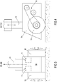
Figure 3 shows a first detailed view of a portion of the industrial carriage offigure 1 ; -
Figure 4 shows a second detailed view of a portion of the industrial carriage offigure 1 ; -
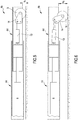
Figure 5 shows a third detailed view of a portion of the industrial carriage offigure 1 , in a first operating configuration; and -
Figure 6 shows a fourth detailed view of a portion of the industrial carriage offigure 1 , in a second operating configuration. - With reference to the attached figures, and in particular to
figure 1 it is indicated in its entirety an industrial carriage, suitable for transporting and lifting loads installed and/or positioned on pallet. - With reference to the present description, for "pallet" it is intended a tool used for supporting various types of material, designed to be stored in industries, to be moved with specific tools. Preferably but in a non-limiting extent, the pallet has a wood structure provided with at least a pair of holes, passing preferably from part to part, such as to permit the introduction or insertion of a fork comprising a pair of arms.
- The industrial carriage 1 object of the invention is then advantageously configured for permitting the transport of loads both on pallet of European standard size, that is equal to 800x1200mm, and on pallet of other size, sensibly bigger also in the order of 2 meters per side. The industrial carriage 1 object of the invention is also configured for operating as carriage for transporting relevant weight loads, also in the order of 20t.
- The industrial carriage 1, that is configured as a transpallet machine, is a carriage that comprises a metallic supporting
frame 2, in particular preferably realized at least partially in stainless steel, on which is fixed a pair of carriages that comprises a first and asecond carriage second carriage frame 2 and are substantially installed in correspondence with the left and right ending of this supportingframe 2, such that to maximize the reciprocal distance and define a rear support base for the distribution of the weight that is the maximum possible. - The Applicant underlines that even if in the attached figures there is reference to an industrial carriage provided with a first and a
second carriage second carriage single carriage 3a, still positioned in the rear position on the industrial carriage 1; if there is asingle carriage 3a, this carriage is preferably but in a non-limiting extent centered on the longitudinal axis of the industrial carriage 1 itself, then on the first reference axis Y. If there is asingle carriage 3a, the industrial carriage 1 has three supporting points on the ground, of which one on the rear side and two on the front side, in correspondence with arms, as it will be better described by the following part of description. - Peculiar characteristics of the industrial carriage 1 object of the invention are having a fork the
arms arms - In order to reach the aforementioned purposes, to the supporting
frame 2 is connected aload portion 4, comprising a firstcarriaged arm 4a and a secondcarriaged arm 4b configured for permitting the loading of at least one pallet. Preferably but in a non-limiting extent also the first and secondcarriaged arm - The first and second
carriaged arm carriaged arm - According to an important aspect of the invention, the first
carriaged arm 4a and the secondcarriaged arm 4b have each one a wheel orroller 5 as support to the load. Advantageously, the contemporary presence of a wheel orroller 5 on eachcarriaged arm carriage - The use of a first and second
rear carriage rollers 5 on each of thecarriaged arms - In order to maximize the area upon which the weight of the load is distributed in use, advantageously the Applicant has provided for positioning the wheels or
rollers 5 in correspondence with a substantial correspondence of the ending ofarms frame 2; in particular, this ending is the front ending of each of said firstcarriaged arm 4a and secondcarriaged arm 4b. - In order to distribute the weight of also big loads, in particular when installed on pallets of non standard size, and particularly bigger than the standard sized pallets, the Applicant has advantageously conceived the fork such that the first and second
carriaged arm first portion 4c and asecond portion 4d. Thefirst portion 4c is the one nearest the supportingframe 2, whereas thesecond portion 4d is the one most distant with respect to the supportingframe 2. In particular thesecond portion 4d of each arm is configured for sliding with respect to thefirst portion 4c of the arm itself. - The first and the
second portion carriaged arm second portion second portion 4d with respect to thefirst portion 4c takes place along a direction substantially parallel to the first reference axis Y, between at least a first configuration wherein thesecond portion 4d enters for a first, and preferably maximal, measure within thefirst portion 4c and a second configuration wherein thesecond portion 4d enters for a second, and preferably minimal, measure inside thefirst portion 4c. The use of arms the extension of which is adjustable permits to reduce the risk of wrong positioning of the load, and in particular permits to reduce the levers that are created with loads the center of gravity of which is unbalanced. - The extension of the
second portion 4d with respect to thefirst portion 4c permits thus advantageously to make the assembly formed by the first and second portion as long as at least the depth of pallets of also different sizes, avoiding from one side that the fork rises significantly further than the shape in plane view of the pallet or load and at the same time, through an opportune adjustment, permitting to avoid the risk of collapse and consequent tipping of the load; in case on the industrial carriage 1 are loaded shorter pallets, thesecond portion 4d can be further introduced in thefirst portion 4c, whereas in case on the industrial carriage 1 are loaded deeper pallets, thesecond portion 4d can be further extracted from thefirst portion 4d. - With the first and the second portion of each
carriaged arm actuators 6 that control the movement of thesecond portion 4d with respect to thefirst portion 4c. In a preferred embodiment, the first and thesecond portion second arm second portion carriaged arm actuators 6 are - as schematically shown in the attached figures - linear actuators comprising at least a hydraulic piston. The boxed shape is not to be intended as limiting, because it is possible to realize the first and the second portion of eacharm - When the
actuators 6 are linear actuators comprising at least a hydraulic piston, these actuators have a first ending constrained to thefirst portion 4c of a respective arm and asecond ending 4d constrained instead to thesecond portion 4d of the respective arm. The extension and the shortening of the movable portion of the hydraulic piston determines the possibility of movement of thesecond portion 4d with respect to thefirst portion 4c of each of the first and secondcarriaged arm - The wheels or
rollers 5 are installed in correspondence with thesecond portion 4d of eacharm carriaged arm - In particular, in order to compensate the unbalance of big loads and, in association, to permit to compensate the non-uniformity of the ground on which in use the industrial carriage 1 lies, the Applicant has designed to install the wheels or
rollers 5 in a movable way with respect to respectivefirst arm 4a, orsecond arm 4b. Particularly, the wheels are installed onsupports 14 that permit a movement at least between a position with respect to respective first or secondcarriaged arm second portion 4d of the respective first or secondcarriaged arm carriaged arm roller 5 can be at least at a first distance q1 from thesecond portion 4d of the respectivecarriaged arm second portion 4d of the respectivecarriaged arm Figures 5 and 6 show two configurations wherein the axis of the wheel orroller 5 is nearer to thesecond portion 4d of the respective arm (figure 5 ) and more distant with respect to thesecond portion 4d of the respective arm (figure 6 ) and show heights for said first and second distances q1, q2. The wheels orrollers 5 with therespective supports 14 form therefore part of the system of compensation of unbalances of load and/or compensation of the slope. - Preferably, this distance is a distance that when the industrial carriage 1 is in use is substantially vertical, and is therefore measured along a second reference axis X that is orthogonal with respect to the first reference axis Y. The variation of this distance determines a variation of the distance from the ground of the second portion of each arm. By assuming a substantial rigidity of the assembly formed by each first and
second portion carriaged arm roller 5 has with respect to the first andsecond portion carriaged arm - The movement of the axis of the wheel or
roller 5 of the first and secondcarriaged arm second portion 4d both of the first and of the secondcarriaged arm roller 5 of the first or of the secondcarriaged arm roller 5 of the opposed carriaged arm; this configuration permits to compensate the slope also in transversal direction with respect to the direction detected by the first reference axis Y. - According to a preferred and non-limiting embodiment of the invention here described and shown in the attached figures, each of the
arms secondary actuator 13 for the movement of the wheel orroller 5. In particular, the wheel orroller 5 of each of said first andsecond arm secondary actuator 13 of linear type, more preferably comprising at least a hydraulic piston. By using an actuator with hydraulic piston is advantageously possible to vary the position of the wheel orroller 5, in particular the position of its axis with respect to thesecond portion 4d of each one between the first andsecond arm secondary actuators 13 are parts of the system of compensation of unbalances of load and/or compensation of the slope. It is to be noticed that the independent functioning of thesecondary actuators 13 permits to realize a compensation both along the first reference axis Y - in case of simultaneous functioning - and a compensation along the first reference axis and along the second reference axis Z - in case of an independent and not simultaneous actuation. - In the preferred and not-limiting embodiment shown in the attached figures, also the
secondary actuator 13 is contained in the respective arm, more in particular resulting installed completely within thesecond portion 4d of the respective first,second arm 4d. Clearly this solution is possible when at least thesecond portion 4d of each one between the first andsecond arm second portion 4d and a second ending, mobile with respect to the first ending. The second ending is, in detail, fixed to thesupport 14 of the wheel orroller 5. - The Applicant has observed that the compensation of the unbalance of the load, with the flexibility of operability for the movement of pallets also of non standard sizes is advantageously optimized also by a possibility of adjustment of the transversal distance between the first and
second arm carriaged arm second arm transversal actuator 23, conjoined to the first and to thesecond arm transversal actuators 23 are preferably but not limiting parallel the one to the other, overlaid or juxtaposed, and extended in direction opposed the one with respect to the other. They have in fact a first ending fixed to said supportingframe 2 and a second ending, mobile with respect to the first ending, constrained to the respective firstcarriaged arm 4a or secondcarriaged arm 4b. Preferably, but not limiting, the first and the second transversal actuator are linear actuators comprising a hydraulic piston. - The first and
second arm - In order to optimize the stability of big loads, big sizes, particularly unbalanced, and in particular if of relevant weight, and for obtaining a stability that can compensate also the not uniformity of the ground on which in use the industrial carriage 1 lies and moves, the first and the
second carriage frame 2, specifically movable along said second reference axis X between at least a first and a second position different between them. - More in particular, as it is possible to notice from
figures 1 ,3 and 4 , each one between the first and thesecond carriage actuator 19 that permits to vary the position with respect to the supportingframe 2. In particular, theactuator 19 of each carriage permits to vary the position that the axis of thewheel 10 of eachcarriage frame 2, in particular to vary the position with respect to the first direction detected by the second reference axis X. This advantageously permits to increase or lower the supportingframe 2 and/or the rear side of the industrial carriage 1 with respect to the ground. - Preferably but not limiting, the
actuators 19 are linear actuators that comprise a hydraulic piston, the direction of which of substantial and/or main development is parallel to the second reference axis X. In detail, the hydraulic piston comprises a first ending with the respectivefirst carriage 3a orsecond carriage 3b and a second ending, mobile with respect to said first ending, united to the supporting frame. - The use of two
separate actuators 19, one for thefirst carriage 3a, and one for thesecond carriage 3b advantageously permits to obtain independence of movement of the first and of thesecond carriage - The independence of functioning of the
actuators 19 for the first and thesecond carriage auxiliary actuators 13 for the wheels orrollers 5 of the first andsecond arm - The industrial carriage 1 here described is preferably a self-propelled carriage; in this advantageous case, each between the first and the
second carriage wheels 10 opposed the one to the other united to a mechanism of active movement, that permits the clockwise and counterclockwise rotation of them. Advantageously, the Applicant for this reason has designedcarriages motor 11 for carriage and preferably two motors per carriage. - As it is shown in
figure 3 and infigure 4 , the first and thesecond carriage wheel 10 of therespective carriage figure 4 , the shaft of themotor 11 is coupled with a transmission system, in particular achain transmission 18 that permits to transfer the movement toward therespective wheel 10. Thechain transmission 18 takes place on at least a pinion-crown pair that advantageously can be opportunely sized in order to reduce, if necessary, the transmission ratio toward the respective wheel. The use of a chain transmission must not be intended as limiting, since it is possible alternatively to use a belted or other type of transmission, provided that it is capable of transferring the movement in a substantially rigid way from themotor 11 to thewheel 10. - If each
carriage motors 11, each motor will control arespective wheel 10, preferably by means of itschain transmission 18 respectively positioned on the left and/or right side of thecarriage wheels 10 not only in a mutual way but also in a non mutual way, advantageously permitting to thecarriage - Preferably but in a non-limiting extent, the
motor 11 of eachcarriage - The Applicant has in particular observed that when the actuators previously described are hydraulic pistons, there is particular convenience in the use of a
hydraulic motor 11 also in this case. In this way it is possible to define a uniquehydraulic control unit 30, conveniently positioned on the supportingframe 2, provided with suppliers suitable to give pressure in a selective way to at least part of the actuators of the industrial carriage 1 according to the control needs. - Preferably but in a non-limiting extent, the industrial carriage 1 comprises also a
data processing unit 20, electrically connected with thehydraulic control unit 30 that in turn comprises a liquid pump preferably of electro-actuated type. This data processing unit is configured for causing the opening and/or closing, total or partial of the electro-valves of the supplier in thehydraulic control unit 30, alternatively according to a movement program carried out autonomously or according to control signals deriving from a remote controller controlled by the user. - The remote controller controlled by the user can be a cabled remote controller electrically connected to the data processing unit, or alternatively be a wireless remote controller. In this case, conveniently, the
data processing unit 20 will be provided with anantenna 21 for the radio data transmission. The data processing unit can be a processor of general purpose type specifically configured through said software program or firmware for carrying out one or more parts of the method detected in the present invention or be an ASIC or dedicated processor, specifically programmed for executing at least part of the operations of the method or control process of the industrial carriage 1 object of the invention. - In use the industrial carriage 1 can be used as follows. When a load on a pallet must be transported, at first the user provides for detecting the pitch of holes of the pallet where it must be introduced the fork. If the pitch of the pallet that must be transported is not equal to the pitch of the fork, the reciprocal distance between the first and second
carriaged arm - By means of operating the remote controller the user can also adjust the height of the front portion of the industrial carriage 1, by means of the control of the
auxiliary actuators 13 such as to bring the axis of the wheels orrollers 5 to a height sufficient for permitting the introduction of the first and secondcarriaged arm - If the length of the
carriaged arms first portion 4c and of thesecond portion 4d, the user through the use of the remote controller can adjust the length of arms in particular by letting out a portion bigger than theportion 4d with respect to thefirst portion 4c. Conveniently the extension can be ended when the length of thefirst portion 4c and the length of thesecond portion 4d are equal or substantially equal to the depth of the pallet. - At this point, through a new action on the remote controller, the user can actuate the actuators of the first and
second carriage rollers 5 such as to cause a uniform substantially lifting of the pallet and then of the load from the ground. This operation substantially causes that the movement of the actuators of the first andsecond carriage rollers 5 is substantially simultaneous. According to the present invention, as lifting of the carriage is intended a lifting of the height at which are positioned the at least first and the secondcarriaged arm second arm - Thanks to the possibility of actuating
motors 11, the load on the industrial carriage 1 can be moved without effort; through the functioning of the remote controller, the user can control the industrial carriage 1 both in substantially linear translation on curved paths in direction parallel to the first reference axis Y or diagonally with respect to this last one. - If the industrial carriage 1 encounters slopes, the
auxiliary actuators 13 for the wheels orrollers 5 and theactuators 19 of the first andsecond carriage auxiliary actuators 13 for wheels orrollers 5, during the lifting of thesecond portion 4d with respect to the ground (by compensating a descent) or during the lowering of thesecond portion 4d with respect to the ground (by compensating an ascent) and/or with a simultaneous functioning of theactuators 19 of the first andsecond carriage - A compensation of slopes substantially parallel to the third reference axis Z takes place with a simultaneous functioning of the
secondary actuator 13 for the wheels orrollers 5 and of theactuator 19 for thecarriage - The compensation of the slope along said first and second reference axis Y, Z can be then carried out manually through said remote controller; alternatively, the compensation of the slope along said first and third reference axis can be automatically carried out. In this case, conveniently, an embodiment of the industrial carriage 1 comprises sensors for positioning and/or inclination configured for detecting inclinations at least of the first and second
carriaged arm data processing unit 20 with known technique that is then here not described. If the industrial carriage 1 is provided with a data processing unit configured for operating an automatic compensation along the first reference axis Y and the third reference axis Z, advantageously thisdata processing unit 20 is configured also for permitting the commutation between this automatic compensation and a manual compensation of the slope and/or of the unbalance of the load. - When the
data processing unit 20 is configured for carrying out an automatic compensation along said first reference axis Y and along said third reference axis Z, thisdata processing unit 20 configures itself in an operating configuration wherein at regular intervals it receives from the sensors positioning and/or inclination data of the industrial carriage along the first reference axis Y and along the third reference axis Z, and according to these inclination data, provides for compensating it by means of an activation of theactuators 19 of the first and/orsecond carriage secondary actuators 13 of the first and/or of the secondcarriaged arm - The control unit and the
hydraulic control unit 30 are preferably supplied by a battery or a plurality of batteries installed on board. This battery or plurality of batteries is typically of rechargeable type and when enough recharged autonomously provides energy to the industrial carriage 1, making it an operationally self-supplied carriage, that is free from needing a connection to an external energy source, in particular free from needing a continuous connection to an external energy source. For this reason, the industrial carriage 1 here described can be defined as a self-supplied carriage. However, it is possible to configure the carriage for having an auxiliary supply supplied from the outside, for example and in a non-limiting extent, deriving from a domestic net electrical supply source - 230v - or industrial - 380 V - of a single or three phase type, as aid and support to the battery. - It is finally clear that to the industrial carriage object of the invention can be applied additions, changes or variants obvious for an expert in the art without editing from the scope provided by the attached claims.
Claims (15)
- Industrial carriage, in particular for transporting loads on pallet comprising:- a supporting frame (2);- at least a first carriage (3a), installed on said supporting frame (2);- a loading portion (4), comprising a first arm (4a) and a second arm (4b) designed for permitting the loading of at least one pallet; said first arm and said second arm (4a, 4b) developing themselves each one substantially linearly along a direction detected by a first reference axis (Y);
said industrial carriage (1) being characterized by the fact that said first and said second arm (4a, 4b) comprise each one at least a first portion (4c) and a second portion (4d); said first and second arm (4a, 4b) comprising at least a first operating configuration within which said first portion (4c) and second portion (4d) define a first length of the respective first and/or second arm (4a, 4b) and a second operating configuration within which said first portion (4c) and second portion (4d) define a second length of the respective first and/or second arm (4a, 4b). - Industrial carriage according to claim 1, further comprising a second carriage (2) installed on said supporting frame, and wherein the first carriage (3a), and optionally said second carriage (3b) are pivotally installed on said supporting frame (2) and rotate with respect to a second reference axis (X) orthogonal with respect to said first reference axis (Y).
- Industrial carriage according to claim 1 or claim 2, comprising a compensation system of load unbalances and/or of slope compensation, said compensation system being configured for operating along said first reference axis (Y) and/or along a third reference axis (Z) orthogonal with respect to said first reference axis (Y).
- Industrial carriage according to claim 3, wherein said compensation system comprises at least an actuator (19), preferably linear, for said first carriage (3a), and optionally an actuator, preferably linear, for said second carriage (3b), said actuator (19), preferably linear, being configured for arranging in at least a first operating configuration in correspondence of which said first carriage (3a), and optionally said second carriage (3b) are in a first position with respect to said supporting frame, and in a second operating configuration in correspondence of which said first carriage (3a), and optionally said second carriage (3b), are in a second position with respect to said supporting frame (2), said second position being different from said first position.
- Industrial carriage according to claim 4, wherein said compensation system comprises at least a linear actuator (19), for said first carriage (3a), and a linear actuator (19) for said second carriage (3b), and wherein each one of said linear actuators (19) is configured for arranging in at least a first operating configuration in correspondence of which said first carriage (3a) and/or said second carriage (3b) are in a first position with respect to said supporting frame, and in a second operating configuration in correspondence of which said first carriage (3a) and/or said second carriage (3b) are in a second position with respect to said supporting frame (2), said second position being different from said first position and wherein said actuator for said first carriage (3a) is operable independently from said actuator for said second carriage (3b).
- Industrial carriage according to one of the previous claims 2-5, wherein said first carriage (3a) and optionally said second carriage (3b) comprise each one a first and a second wheel (10) and at least a first motor (11) connected to said first wheel (10) and/or to said second wheel.
- Industrial carriage according to claim 6, wherein said first carriage (3a) and said second carriage (3b) comprise each one a first and a second wheel (10) a first motor (11) connected to said first wheel (10) and a second motor connected to said second wheel (10) wherein said first and said second motor are configured:- for actuating in rotation said first and said second wheel (10) in the same sense of rotation;- for actuating in rotation said first wheel in a sense of rotation opposed with respect to the rotation of said second wheel.
- Industrial carriage according to any of the previous claims, comprising for each first or second arm (4a, 4b), at least an actuator (6), optionally linear, comprising a first portion of ending constrained to said first portion (4c) of the respective installation arm, and a second portion of ending constrained to said second portion (4d) of the respective installation arm, and wherein said actuator (6), optionally linear, in said first operating configuration causes a first extension of said second portion (4d) of the respective arm with respect to said first portion (4c), and in said second operating configuration it causes a second extension of said second portion (4d) of the respective arm respective to said first portion (4c), said second extension being longer than said first extension, and being in particular a maximal extension.
- Industrial carriage according to any of the previous claims, wherein said first arm (4a) and/or said second arm (4b) are carriaged arms provided with at least a wheel or roller (5) configured for supporting the respective arm with respect to a supporting plan or ground upon which in use the respective arm lies, said at least a wheel or roller (5) being idly installed on said arm.
- Industrial carriage according to claim 8, wherein said at least a wheel or roller is installed in correspondence of said second portion (4d) of said first arm (4a) and of said second arm (4b).
- Industrial carriage according to claim 9 or claim 10, comprising a compensation system of load unbalances and/or of slope compensation, said compensation system being configured for operating along said first reference axis (Y) and/or along a third reference axis (Z) orthogonal with respect to said first reference axis (Y), wherein said compensation system comprises a movable support (14) for said at least a wheel or roller (5), said movable support being installed in correspondence of said first arm (4a) and/or of said second arm (4b); said movable support being configured for allowing said wheel or roller a movement between a first position wherein the axis of said wheel or roller is in a first position with respect to said arm and a second position wherein the axis of said wheel or roller is in a second position with respect to said arm.
- Industrial carriage according to claim comprising an actuator (13) preferably linear, installed in correspondence of the second portion (4d) of said first and/or second arm (4a; 4b), said actuator (13) being configured for operating in movement said movable support (14) at least between said first and said second position.
- Industrial carriage according to any of the previous claims, comprising also a system of transversal movement for said first and second arm (4a, 4b), configured for permitting to vary the positioning of the first and second arm (4a, 4b) at least between a first reciprocal distance and a second reciprocal distance; said system of transversal movement comprising at least a linear actuator (6) of preferably pneumatic or hydraulic type.
- Industrial carriage according to any of the previous claims 3-5, comprising a data processing unit (20) configured for arranging in at least a first operating configuration wherein it controls said compensation system in a substantially automatic way.
- Industrial carriage according to any of the previous claims 3-5, wherein said compensation system of load unbalances and/or of slope compensation is configured for permitting to vary the height that said first and second arm (4a, 4b) have in use with respect to the ground.
Priority Applications (1)
| Application Number | Priority Date | Filing Date | Title |
|---|---|---|---|
| EP17194825.0A EP3466794B1 (en) | 2017-10-04 | 2017-10-04 | Industrial carriage, in particular for transporting loads on pallet |
Applications Claiming Priority (1)
| Application Number | Priority Date | Filing Date | Title |
|---|---|---|---|
| EP17194825.0A EP3466794B1 (en) | 2017-10-04 | 2017-10-04 | Industrial carriage, in particular for transporting loads on pallet |
Publications (2)
| Publication Number | Publication Date |
|---|---|
| EP3466794A1 true EP3466794A1 (en) | 2019-04-10 |
| EP3466794B1 EP3466794B1 (en) | 2022-12-07 |
Family
ID=60201296
Family Applications (1)
| Application Number | Title | Priority Date | Filing Date |
|---|---|---|---|
| EP17194825.0A Active EP3466794B1 (en) | 2017-10-04 | 2017-10-04 | Industrial carriage, in particular for transporting loads on pallet |
Country Status (1)
| Country | Link |
|---|---|
| EP (1) | EP3466794B1 (en) |
Cited By (5)
| Publication number | Priority date | Publication date | Assignee | Title |
|---|---|---|---|---|
| CN109987554A (en) * | 2019-05-06 | 2019-07-09 | 杭州易博特科技有限公司 | Reverse telescopic system and automatic handling equipment |
| US20210114644A1 (en) * | 2019-10-18 | 2021-04-22 | Hyster-Yale Group, Inc. | Load wheel designs for pallet entry |
| US12077421B2 (en) | 2019-03-27 | 2024-09-03 | Hyster-Yale Materials Handling, Inc. | Load wheel module for a forked material-handling vehicle |
| US12397836B2 (en) | 2019-03-27 | 2025-08-26 | Hyster-Yale Materials Handling, Inc. | Modular fork assembly for a forked material-handling vehicle |
| WO2026005596A1 (en) * | 2024-06-27 | 2026-01-02 | Meijer Holding B.V. | Pallet truck provided with extendable forks with extending equalizer, system and method therefor |
Citations (7)
| Publication number | Priority date | Publication date | Assignee | Title |
|---|---|---|---|---|
| GB902898A (en) * | 1957-11-21 | 1962-08-09 | C Coupler & Engineering Co Ltd | Improvements in or relating to pallet trucks |
| GB2121759A (en) * | 1982-06-09 | 1984-01-04 | Jungheinrich | Low-level pallet or stillage mover |
| DE9205223U1 (en) | 1992-04-15 | 1992-06-25 | Balduin, Franz, 52076 Aachen | Forklift truck |
| WO2007145508A2 (en) * | 2006-06-15 | 2007-12-21 | Gebr. Meijer St. Jabik B.V. | Pallet truck with extending forks |
| US7744335B1 (en) * | 2003-10-08 | 2010-06-29 | Tamara Cleary | Pallet jack with independently elevatable fork arms |
| DE102009059949A1 (en) * | 2009-12-22 | 2011-06-30 | Jungheinrich Aktiengesellschaft, 22047 | Ground conveyor has lifting device, which is arranged on each of wheel arms and cooperates with wheel arm lever, where drive part is tilted over its drive wheel |
| WO2012171079A1 (en) * | 2011-06-17 | 2012-12-20 | Austech And Design Pty Ltd | Lifting and transporting device for wheeled objects including hospital beds |
-
2017
- 2017-10-04 EP EP17194825.0A patent/EP3466794B1/en active Active
Patent Citations (7)
| Publication number | Priority date | Publication date | Assignee | Title |
|---|---|---|---|---|
| GB902898A (en) * | 1957-11-21 | 1962-08-09 | C Coupler & Engineering Co Ltd | Improvements in or relating to pallet trucks |
| GB2121759A (en) * | 1982-06-09 | 1984-01-04 | Jungheinrich | Low-level pallet or stillage mover |
| DE9205223U1 (en) | 1992-04-15 | 1992-06-25 | Balduin, Franz, 52076 Aachen | Forklift truck |
| US7744335B1 (en) * | 2003-10-08 | 2010-06-29 | Tamara Cleary | Pallet jack with independently elevatable fork arms |
| WO2007145508A2 (en) * | 2006-06-15 | 2007-12-21 | Gebr. Meijer St. Jabik B.V. | Pallet truck with extending forks |
| DE102009059949A1 (en) * | 2009-12-22 | 2011-06-30 | Jungheinrich Aktiengesellschaft, 22047 | Ground conveyor has lifting device, which is arranged on each of wheel arms and cooperates with wheel arm lever, where drive part is tilted over its drive wheel |
| WO2012171079A1 (en) * | 2011-06-17 | 2012-12-20 | Austech And Design Pty Ltd | Lifting and transporting device for wheeled objects including hospital beds |
Cited By (9)
| Publication number | Priority date | Publication date | Assignee | Title |
|---|---|---|---|---|
| US12077421B2 (en) | 2019-03-27 | 2024-09-03 | Hyster-Yale Materials Handling, Inc. | Load wheel module for a forked material-handling vehicle |
| US12397836B2 (en) | 2019-03-27 | 2025-08-26 | Hyster-Yale Materials Handling, Inc. | Modular fork assembly for a forked material-handling vehicle |
| CN109987554A (en) * | 2019-05-06 | 2019-07-09 | 杭州易博特科技有限公司 | Reverse telescopic system and automatic handling equipment |
| EP3967645A4 (en) * | 2019-05-06 | 2022-06-29 | Hangzhou Eiorobot Technology Co., Ltd. | Inverse telescopic system and automatic transportation apparatus |
| JP2022531014A (en) * | 2019-05-06 | 2022-07-05 | 杭州易博特科技有限公司 | Reverse telescopic system and automated conveyor |
| JP7193185B2 (en) | 2019-05-06 | 2022-12-20 | 杭州易博特科技有限公司 | Reverse telescopic system and automatic carrier |
| US20210114644A1 (en) * | 2019-10-18 | 2021-04-22 | Hyster-Yale Group, Inc. | Load wheel designs for pallet entry |
| US11745778B2 (en) * | 2019-10-18 | 2023-09-05 | Hyster-Yale Group, Inc. | Load wheel designs for pallet entry |
| WO2026005596A1 (en) * | 2024-06-27 | 2026-01-02 | Meijer Holding B.V. | Pallet truck provided with extendable forks with extending equalizer, system and method therefor |
Also Published As
| Publication number | Publication date |
|---|---|
| EP3466794B1 (en) | 2022-12-07 |
Similar Documents
| Publication | Publication Date | Title |
|---|---|---|
| EP3466794B1 (en) | Industrial carriage, in particular for transporting loads on pallet | |
| JP7138507B2 (en) | Cart assembly used for workpieces and method of use | |
| US4103795A (en) | Lifting and loading device | |
| KR101707202B1 (en) | Automatic Transfer Vehicle | |
| SI3033295T1 (en) | Device and method for transporting heavy duty racks by means of a transport vehicle on an uneven ground surface | |
| JP5963183B1 (en) | Belt conveyor equipment | |
| JP2009539732A (en) | Pallet truck with extension fork | |
| JP2016113283A (en) | Carriage | |
| TW202313443A (en) | Dolly for gas container | |
| JP2018165188A (en) | Horizontal transport cart | |
| US11377240B2 (en) | Self-propelled wrapping machine | |
| EP3974372B1 (en) | Mobile elevating work platform | |
| CN105452147A (en) | Decentralized linear motor regulation for transport systems | |
| IT201900018926A1 (en) | APPARATUS FOR OPERATING THE FORK SUPPORTS OF A FORKLIFT | |
| JP5765577B2 (en) | Stacker crane | |
| CN114435976B (en) | Automatic container packing system and method | |
| EP3882459A1 (en) | Mobile lifting apparatus and method and system for transporting a component of a wind turbine | |
| JP2021017131A (en) | Carriage | |
| EP0577172B1 (en) | Automated apparatus for loading and unloading motor vehicles | |
| KR101626146B1 (en) | Spider lift carrier | |
| CN106829551A (en) | Automatic roller machine truck-loading facilities | |
| CN218023497U (en) | Carrying robot and warehousing system | |
| JP2019099064A (en) | Heavy cargo carrying carriage and cargo handling method of heavy cargo | |
| WO2012080755A1 (en) | Improvements in or relating to load handling apparatus | |
| KR20130127316A (en) | Handcart |
Legal Events
| Date | Code | Title | Description |
|---|---|---|---|
| PUAI | Public reference made under article 153(3) epc to a published international application that has entered the european phase |
Free format text: ORIGINAL CODE: 0009012 |
|
| STAA | Information on the status of an ep patent application or granted ep patent |
Free format text: STATUS: THE APPLICATION HAS BEEN PUBLISHED |
|
| AK | Designated contracting states |
Kind code of ref document: A1 Designated state(s): AL AT BE BG CH CY CZ DE DK EE ES FI FR GB GR HR HU IE IS IT LI LT LU LV MC MK MT NL NO PL PT RO RS SE SI SK SM TR |
|
| AX | Request for extension of the european patent |
Extension state: BA ME |
|
| STAA | Information on the status of an ep patent application or granted ep patent |
Free format text: STATUS: REQUEST FOR EXAMINATION WAS MADE |
|
| 17P | Request for examination filed |
Effective date: 20191009 |
|
| RBV | Designated contracting states (corrected) |
Designated state(s): AL AT BE BG CH CY CZ DE DK EE ES FI FR GB GR HR HU IE IS IT LI LT LU LV MC MK MT NL NO PL PT RO RS SE SI SK SM TR |
|
| REG | Reference to a national code |
Ref country code: DE Ref legal event code: R079 Ref document number: 602017064328 Country of ref document: DE Free format text: PREVIOUS MAIN CLASS: B62B0003060000 Ipc: B62B0005000000 |
|
| RIC1 | Information provided on ipc code assigned before grant |
Ipc: B62B 3/06 20060101ALI20211022BHEP Ipc: B62B 5/00 20060101AFI20211022BHEP |
|
| GRAP | Despatch of communication of intention to grant a patent |
Free format text: ORIGINAL CODE: EPIDOSNIGR1 |
|
| STAA | Information on the status of an ep patent application or granted ep patent |
Free format text: STATUS: GRANT OF PATENT IS INTENDED |
|
| GRAJ | Information related to disapproval of communication of intention to grant by the applicant or resumption of examination proceedings by the epo deleted |
Free format text: ORIGINAL CODE: EPIDOSDIGR1 |
|
| INTG | Intention to grant announced |
Effective date: 20220202 |
|
| STAA | Information on the status of an ep patent application or granted ep patent |
Free format text: STATUS: REQUEST FOR EXAMINATION WAS MADE |
|
| INTC | Intention to grant announced (deleted) | ||
| GRAP | Despatch of communication of intention to grant a patent |
Free format text: ORIGINAL CODE: EPIDOSNIGR1 |
|
| STAA | Information on the status of an ep patent application or granted ep patent |
Free format text: STATUS: GRANT OF PATENT IS INTENDED |
|
| INTG | Intention to grant announced |
Effective date: 20220511 |
|
| GRAS | Grant fee paid |
Free format text: ORIGINAL CODE: EPIDOSNIGR3 |
|
| GRAA | (expected) grant |
Free format text: ORIGINAL CODE: 0009210 |
|
| STAA | Information on the status of an ep patent application or granted ep patent |
Free format text: STATUS: THE PATENT HAS BEEN GRANTED |
|
| AK | Designated contracting states |
Kind code of ref document: B1 Designated state(s): AL AT BE BG CH CY CZ DE DK EE ES FI FR GB GR HR HU IE IS IT LI LT LU LV MC MK MT NL NO PL PT RO RS SE SI SK SM TR |
|
| REG | Reference to a national code |
Ref country code: GB Ref legal event code: FG4D |
|
| REG | Reference to a national code |
Ref country code: CH Ref legal event code: EP Ref country code: AT Ref legal event code: REF Ref document number: 1536150 Country of ref document: AT Kind code of ref document: T Effective date: 20221215 |
|
| REG | Reference to a national code |
Ref country code: DE Ref legal event code: R096 Ref document number: 602017064328 Country of ref document: DE |
|
| REG | Reference to a national code |
Ref country code: IE Ref legal event code: FG4D |
|
| REG | Reference to a national code |
Ref country code: LT Ref legal event code: MG9D |
|
| REG | Reference to a national code |
Ref country code: NL Ref legal event code: MP Effective date: 20221207 |
|
| PG25 | Lapsed in a contracting state [announced via postgrant information from national office to epo] |
Ref country code: SE Free format text: LAPSE BECAUSE OF FAILURE TO SUBMIT A TRANSLATION OF THE DESCRIPTION OR TO PAY THE FEE WITHIN THE PRESCRIBED TIME-LIMIT Effective date: 20221207 Ref country code: NO Free format text: LAPSE BECAUSE OF FAILURE TO SUBMIT A TRANSLATION OF THE DESCRIPTION OR TO PAY THE FEE WITHIN THE PRESCRIBED TIME-LIMIT Effective date: 20230307 Ref country code: LT Free format text: LAPSE BECAUSE OF FAILURE TO SUBMIT A TRANSLATION OF THE DESCRIPTION OR TO PAY THE FEE WITHIN THE PRESCRIBED TIME-LIMIT Effective date: 20221207 Ref country code: FI Free format text: LAPSE BECAUSE OF FAILURE TO SUBMIT A TRANSLATION OF THE DESCRIPTION OR TO PAY THE FEE WITHIN THE PRESCRIBED TIME-LIMIT Effective date: 20221207 Ref country code: ES Free format text: LAPSE BECAUSE OF FAILURE TO SUBMIT A TRANSLATION OF THE DESCRIPTION OR TO PAY THE FEE WITHIN THE PRESCRIBED TIME-LIMIT Effective date: 20221207 |
|
| REG | Reference to a national code |
Ref country code: AT Ref legal event code: MK05 Ref document number: 1536150 Country of ref document: AT Kind code of ref document: T Effective date: 20221207 |
|
| PG25 | Lapsed in a contracting state [announced via postgrant information from national office to epo] |
Ref country code: RS Free format text: LAPSE BECAUSE OF FAILURE TO SUBMIT A TRANSLATION OF THE DESCRIPTION OR TO PAY THE FEE WITHIN THE PRESCRIBED TIME-LIMIT Effective date: 20221207 Ref country code: PL Free format text: LAPSE BECAUSE OF FAILURE TO SUBMIT A TRANSLATION OF THE DESCRIPTION OR TO PAY THE FEE WITHIN THE PRESCRIBED TIME-LIMIT Effective date: 20221207 Ref country code: LV Free format text: LAPSE BECAUSE OF FAILURE TO SUBMIT A TRANSLATION OF THE DESCRIPTION OR TO PAY THE FEE WITHIN THE PRESCRIBED TIME-LIMIT Effective date: 20221207 Ref country code: HR Free format text: LAPSE BECAUSE OF FAILURE TO SUBMIT A TRANSLATION OF THE DESCRIPTION OR TO PAY THE FEE WITHIN THE PRESCRIBED TIME-LIMIT Effective date: 20221207 Ref country code: GR Free format text: LAPSE BECAUSE OF FAILURE TO SUBMIT A TRANSLATION OF THE DESCRIPTION OR TO PAY THE FEE WITHIN THE PRESCRIBED TIME-LIMIT Effective date: 20230308 |
|
| P01 | Opt-out of the competence of the unified patent court (upc) registered |
Effective date: 20230414 |
|
| PG25 | Lapsed in a contracting state [announced via postgrant information from national office to epo] |
Ref country code: NL Free format text: LAPSE BECAUSE OF FAILURE TO SUBMIT A TRANSLATION OF THE DESCRIPTION OR TO PAY THE FEE WITHIN THE PRESCRIBED TIME-LIMIT Effective date: 20221207 |
|
| PG25 | Lapsed in a contracting state [announced via postgrant information from national office to epo] |
Ref country code: SM Free format text: LAPSE BECAUSE OF FAILURE TO SUBMIT A TRANSLATION OF THE DESCRIPTION OR TO PAY THE FEE WITHIN THE PRESCRIBED TIME-LIMIT Effective date: 20221207 Ref country code: RO Free format text: LAPSE BECAUSE OF FAILURE TO SUBMIT A TRANSLATION OF THE DESCRIPTION OR TO PAY THE FEE WITHIN THE PRESCRIBED TIME-LIMIT Effective date: 20221207 Ref country code: PT Free format text: LAPSE BECAUSE OF FAILURE TO SUBMIT A TRANSLATION OF THE DESCRIPTION OR TO PAY THE FEE WITHIN THE PRESCRIBED TIME-LIMIT Effective date: 20230410 Ref country code: EE Free format text: LAPSE BECAUSE OF FAILURE TO SUBMIT A TRANSLATION OF THE DESCRIPTION OR TO PAY THE FEE WITHIN THE PRESCRIBED TIME-LIMIT Effective date: 20221207 Ref country code: CZ Free format text: LAPSE BECAUSE OF FAILURE TO SUBMIT A TRANSLATION OF THE DESCRIPTION OR TO PAY THE FEE WITHIN THE PRESCRIBED TIME-LIMIT Effective date: 20221207 Ref country code: AT Free format text: LAPSE BECAUSE OF FAILURE TO SUBMIT A TRANSLATION OF THE DESCRIPTION OR TO PAY THE FEE WITHIN THE PRESCRIBED TIME-LIMIT Effective date: 20221207 |
|
| PG25 | Lapsed in a contracting state [announced via postgrant information from national office to epo] |
Ref country code: SK Free format text: LAPSE BECAUSE OF FAILURE TO SUBMIT A TRANSLATION OF THE DESCRIPTION OR TO PAY THE FEE WITHIN THE PRESCRIBED TIME-LIMIT Effective date: 20221207 Ref country code: IS Free format text: LAPSE BECAUSE OF FAILURE TO SUBMIT A TRANSLATION OF THE DESCRIPTION OR TO PAY THE FEE WITHIN THE PRESCRIBED TIME-LIMIT Effective date: 20230407 Ref country code: AL Free format text: LAPSE BECAUSE OF FAILURE TO SUBMIT A TRANSLATION OF THE DESCRIPTION OR TO PAY THE FEE WITHIN THE PRESCRIBED TIME-LIMIT Effective date: 20221207 |
|
| REG | Reference to a national code |
Ref country code: DE Ref legal event code: R097 Ref document number: 602017064328 Country of ref document: DE |
|
| PLBE | No opposition filed within time limit |
Free format text: ORIGINAL CODE: 0009261 |
|
| STAA | Information on the status of an ep patent application or granted ep patent |
Free format text: STATUS: NO OPPOSITION FILED WITHIN TIME LIMIT |
|
| PG25 | Lapsed in a contracting state [announced via postgrant information from national office to epo] |
Ref country code: DK Free format text: LAPSE BECAUSE OF FAILURE TO SUBMIT A TRANSLATION OF THE DESCRIPTION OR TO PAY THE FEE WITHIN THE PRESCRIBED TIME-LIMIT Effective date: 20221207 |
|
| 26N | No opposition filed |
Effective date: 20230908 |
|
| PG25 | Lapsed in a contracting state [announced via postgrant information from national office to epo] |
Ref country code: SI Free format text: LAPSE BECAUSE OF FAILURE TO SUBMIT A TRANSLATION OF THE DESCRIPTION OR TO PAY THE FEE WITHIN THE PRESCRIBED TIME-LIMIT Effective date: 20221207 |
|
| REG | Reference to a national code |
Ref country code: DE Ref legal event code: R119 Ref document number: 602017064328 Country of ref document: DE |
|
| PG25 | Lapsed in a contracting state [announced via postgrant information from national office to epo] |
Ref country code: MC Free format text: LAPSE BECAUSE OF FAILURE TO SUBMIT A TRANSLATION OF THE DESCRIPTION OR TO PAY THE FEE WITHIN THE PRESCRIBED TIME-LIMIT Effective date: 20221207 |
|
| REG | Reference to a national code |
Ref country code: CH Ref legal event code: PL |
|
| REG | Reference to a national code |
Ref country code: BE Ref legal event code: MM Effective date: 20231031 |
|
| PG25 | Lapsed in a contracting state [announced via postgrant information from national office to epo] |
Ref country code: LU Free format text: LAPSE BECAUSE OF NON-PAYMENT OF DUE FEES Effective date: 20231004 |
|
| GBPC | Gb: european patent ceased through non-payment of renewal fee |
Effective date: 20231004 |
|
| PG25 | Lapsed in a contracting state [announced via postgrant information from national office to epo] |
Ref country code: LU Free format text: LAPSE BECAUSE OF NON-PAYMENT OF DUE FEES Effective date: 20231004 |
|
| PG25 | Lapsed in a contracting state [announced via postgrant information from national office to epo] |
Ref country code: GB Free format text: LAPSE BECAUSE OF NON-PAYMENT OF DUE FEES Effective date: 20231004 |
|
| PG25 | Lapsed in a contracting state [announced via postgrant information from national office to epo] |
Ref country code: CH Free format text: LAPSE BECAUSE OF NON-PAYMENT OF DUE FEES Effective date: 20231031 |
|
| PG25 | Lapsed in a contracting state [announced via postgrant information from national office to epo] |
Ref country code: GB Free format text: LAPSE BECAUSE OF NON-PAYMENT OF DUE FEES Effective date: 20231004 Ref country code: FR Free format text: LAPSE BECAUSE OF NON-PAYMENT OF DUE FEES Effective date: 20231031 Ref country code: DE Free format text: LAPSE BECAUSE OF NON-PAYMENT OF DUE FEES Effective date: 20240501 Ref country code: CH Free format text: LAPSE BECAUSE OF NON-PAYMENT OF DUE FEES Effective date: 20231031 |
|
| PG25 | Lapsed in a contracting state [announced via postgrant information from national office to epo] |
Ref country code: BE Free format text: LAPSE BECAUSE OF NON-PAYMENT OF DUE FEES Effective date: 20231031 |
|
| PG25 | Lapsed in a contracting state [announced via postgrant information from national office to epo] |
Ref country code: IE Free format text: LAPSE BECAUSE OF NON-PAYMENT OF DUE FEES Effective date: 20231004 |
|
| PG25 | Lapsed in a contracting state [announced via postgrant information from national office to epo] |
Ref country code: IE Free format text: LAPSE BECAUSE OF NON-PAYMENT OF DUE FEES Effective date: 20231004 |
|
| PG25 | Lapsed in a contracting state [announced via postgrant information from national office to epo] |
Ref country code: BG Free format text: LAPSE BECAUSE OF FAILURE TO SUBMIT A TRANSLATION OF THE DESCRIPTION OR TO PAY THE FEE WITHIN THE PRESCRIBED TIME-LIMIT Effective date: 20221207 |
|
| PG25 | Lapsed in a contracting state [announced via postgrant information from national office to epo] |
Ref country code: BG Free format text: LAPSE BECAUSE OF FAILURE TO SUBMIT A TRANSLATION OF THE DESCRIPTION OR TO PAY THE FEE WITHIN THE PRESCRIBED TIME-LIMIT Effective date: 20221207 |
|
| PG25 | Lapsed in a contracting state [announced via postgrant information from national office to epo] |
Ref country code: IT Free format text: LAPSE BECAUSE OF NON-PAYMENT OF DUE FEES Effective date: 20231004 |
|
| PG25 | Lapsed in a contracting state [announced via postgrant information from national office to epo] |
Ref country code: IT Free format text: LAPSE BECAUSE OF NON-PAYMENT OF DUE FEES Effective date: 20231004 |
|
| PG25 | Lapsed in a contracting state [announced via postgrant information from national office to epo] |
Ref country code: CY Free format text: LAPSE BECAUSE OF FAILURE TO SUBMIT A TRANSLATION OF THE DESCRIPTION OR TO PAY THE FEE WITHIN THE PRESCRIBED TIME-LIMIT; INVALID AB INITIO Effective date: 20171004 |
|
| PG25 | Lapsed in a contracting state [announced via postgrant information from national office to epo] |
Ref country code: HU Free format text: LAPSE BECAUSE OF FAILURE TO SUBMIT A TRANSLATION OF THE DESCRIPTION OR TO PAY THE FEE WITHIN THE PRESCRIBED TIME-LIMIT; INVALID AB INITIO Effective date: 20171004 |
|
| PG25 | Lapsed in a contracting state [announced via postgrant information from national office to epo] |
Ref country code: TR Free format text: LAPSE BECAUSE OF FAILURE TO SUBMIT A TRANSLATION OF THE DESCRIPTION OR TO PAY THE FEE WITHIN THE PRESCRIBED TIME-LIMIT Effective date: 20221207 |