EP3466755A2 - Lamp for vehicle and vehicle comprising thereof - Google Patents
Lamp for vehicle and vehicle comprising thereof Download PDFInfo
- Publication number
- EP3466755A2 EP3466755A2 EP18189191.2A EP18189191A EP3466755A2 EP 3466755 A2 EP3466755 A2 EP 3466755A2 EP 18189191 A EP18189191 A EP 18189191A EP 3466755 A2 EP3466755 A2 EP 3466755A2
- Authority
- EP
- European Patent Office
- Prior art keywords
- vehicle
- controller
- lamp
- information
- signal
- Prior art date
- Legal status (The legal status is an assumption and is not a legal conclusion. Google has not performed a legal analysis and makes no representation as to the accuracy of the status listed.)
- Granted
Links
Images







Classifications
-
- B—PERFORMING OPERATIONS; TRANSPORTING
- B60—VEHICLES IN GENERAL
- B60Q—ARRANGEMENT OF SIGNALLING OR LIGHTING DEVICES, THE MOUNTING OR SUPPORTING THEREOF OR CIRCUITS THEREFOR, FOR VEHICLES IN GENERAL
- B60Q1/00—Arrangement of optical signalling or lighting devices, the mounting or supporting thereof or circuits therefor
- B60Q1/02—Arrangement of optical signalling or lighting devices, the mounting or supporting thereof or circuits therefor the devices being primarily intended to illuminate the way ahead or to illuminate other areas of way or environments
- B60Q1/04—Arrangement of optical signalling or lighting devices, the mounting or supporting thereof or circuits therefor the devices being primarily intended to illuminate the way ahead or to illuminate other areas of way or environments the devices being headlights
- B60Q1/14—Arrangement of optical signalling or lighting devices, the mounting or supporting thereof or circuits therefor the devices being primarily intended to illuminate the way ahead or to illuminate other areas of way or environments the devices being headlights having dimming means
- B60Q1/1415—Dimming circuits
- B60Q1/1423—Automatic dimming circuits, i.e. switching between high beam and low beam due to change of ambient light or light level in road traffic
- B60Q1/143—Automatic dimming circuits, i.e. switching between high beam and low beam due to change of ambient light or light level in road traffic combined with another condition, e.g. using vehicle recognition from camera images or activation of wipers
-
- B—PERFORMING OPERATIONS; TRANSPORTING
- B60—VEHICLES IN GENERAL
- B60Q—ARRANGEMENT OF SIGNALLING OR LIGHTING DEVICES, THE MOUNTING OR SUPPORTING THEREOF OR CIRCUITS THEREFOR, FOR VEHICLES IN GENERAL
- B60Q1/00—Arrangement of optical signalling or lighting devices, the mounting or supporting thereof or circuits therefor
- B60Q1/02—Arrangement of optical signalling or lighting devices, the mounting or supporting thereof or circuits therefor the devices being primarily intended to illuminate the way ahead or to illuminate other areas of way or environments
- B60Q1/04—Arrangement of optical signalling or lighting devices, the mounting or supporting thereof or circuits therefor the devices being primarily intended to illuminate the way ahead or to illuminate other areas of way or environments the devices being headlights
- B60Q1/14—Arrangement of optical signalling or lighting devices, the mounting or supporting thereof or circuits therefor the devices being primarily intended to illuminate the way ahead or to illuminate other areas of way or environments the devices being headlights having dimming means
- B60Q1/1446—Arrangement of optical signalling or lighting devices, the mounting or supporting thereof or circuits therefor the devices being primarily intended to illuminate the way ahead or to illuminate other areas of way or environments the devices being headlights having dimming means controlled by mechanically actuated switches
- B60Q1/1492—Foot actuated switches
-
- B—PERFORMING OPERATIONS; TRANSPORTING
- B60—VEHICLES IN GENERAL
- B60Q—ARRANGEMENT OF SIGNALLING OR LIGHTING DEVICES, THE MOUNTING OR SUPPORTING THEREOF OR CIRCUITS THEREFOR, FOR VEHICLES IN GENERAL
- B60Q1/00—Arrangement of optical signalling or lighting devices, the mounting or supporting thereof or circuits therefor
- B60Q1/02—Arrangement of optical signalling or lighting devices, the mounting or supporting thereof or circuits therefor the devices being primarily intended to illuminate the way ahead or to illuminate other areas of way or environments
- B60Q1/04—Arrangement of optical signalling or lighting devices, the mounting or supporting thereof or circuits therefor the devices being primarily intended to illuminate the way ahead or to illuminate other areas of way or environments the devices being headlights
- B60Q1/06—Arrangement of optical signalling or lighting devices, the mounting or supporting thereof or circuits therefor the devices being primarily intended to illuminate the way ahead or to illuminate other areas of way or environments the devices being headlights adjustable, e.g. remotely-controlled from inside vehicle
- B60Q1/08—Arrangement of optical signalling or lighting devices, the mounting or supporting thereof or circuits therefor the devices being primarily intended to illuminate the way ahead or to illuminate other areas of way or environments the devices being headlights adjustable, e.g. remotely-controlled from inside vehicle automatically
- B60Q1/085—Arrangement of optical signalling or lighting devices, the mounting or supporting thereof or circuits therefor the devices being primarily intended to illuminate the way ahead or to illuminate other areas of way or environments the devices being headlights adjustable, e.g. remotely-controlled from inside vehicle automatically due to special conditions, e.g. adverse weather, type of road, badly illuminated road signs or potential dangers
-
- B—PERFORMING OPERATIONS; TRANSPORTING
- B60—VEHICLES IN GENERAL
- B60Q—ARRANGEMENT OF SIGNALLING OR LIGHTING DEVICES, THE MOUNTING OR SUPPORTING THEREOF OR CIRCUITS THEREFOR, FOR VEHICLES IN GENERAL
- B60Q1/00—Arrangement of optical signalling or lighting devices, the mounting or supporting thereof or circuits therefor
- B60Q1/02—Arrangement of optical signalling or lighting devices, the mounting or supporting thereof or circuits therefor the devices being primarily intended to illuminate the way ahead or to illuminate other areas of way or environments
- B60Q1/04—Arrangement of optical signalling or lighting devices, the mounting or supporting thereof or circuits therefor the devices being primarily intended to illuminate the way ahead or to illuminate other areas of way or environments the devices being headlights
- B60Q1/06—Arrangement of optical signalling or lighting devices, the mounting or supporting thereof or circuits therefor the devices being primarily intended to illuminate the way ahead or to illuminate other areas of way or environments the devices being headlights adjustable, e.g. remotely-controlled from inside vehicle
- B60Q1/08—Arrangement of optical signalling or lighting devices, the mounting or supporting thereof or circuits therefor the devices being primarily intended to illuminate the way ahead or to illuminate other areas of way or environments the devices being headlights adjustable, e.g. remotely-controlled from inside vehicle automatically
- B60Q1/10—Arrangement of optical signalling or lighting devices, the mounting or supporting thereof or circuits therefor the devices being primarily intended to illuminate the way ahead or to illuminate other areas of way or environments the devices being headlights adjustable, e.g. remotely-controlled from inside vehicle automatically due to vehicle inclination, e.g. due to load distribution
- B60Q1/115—Arrangement of optical signalling or lighting devices, the mounting or supporting thereof or circuits therefor the devices being primarily intended to illuminate the way ahead or to illuminate other areas of way or environments the devices being headlights adjustable, e.g. remotely-controlled from inside vehicle automatically due to vehicle inclination, e.g. due to load distribution by electric means
-
- B—PERFORMING OPERATIONS; TRANSPORTING
- B60—VEHICLES IN GENERAL
- B60Q—ARRANGEMENT OF SIGNALLING OR LIGHTING DEVICES, THE MOUNTING OR SUPPORTING THEREOF OR CIRCUITS THEREFOR, FOR VEHICLES IN GENERAL
- B60Q1/00—Arrangement of optical signalling or lighting devices, the mounting or supporting thereof or circuits therefor
- B60Q1/02—Arrangement of optical signalling or lighting devices, the mounting or supporting thereof or circuits therefor the devices being primarily intended to illuminate the way ahead or to illuminate other areas of way or environments
- B60Q1/04—Arrangement of optical signalling or lighting devices, the mounting or supporting thereof or circuits therefor the devices being primarily intended to illuminate the way ahead or to illuminate other areas of way or environments the devices being headlights
- B60Q1/06—Arrangement of optical signalling or lighting devices, the mounting or supporting thereof or circuits therefor the devices being primarily intended to illuminate the way ahead or to illuminate other areas of way or environments the devices being headlights adjustable, e.g. remotely-controlled from inside vehicle
- B60Q1/08—Arrangement of optical signalling or lighting devices, the mounting or supporting thereof or circuits therefor the devices being primarily intended to illuminate the way ahead or to illuminate other areas of way or environments the devices being headlights adjustable, e.g. remotely-controlled from inside vehicle automatically
- B60Q1/12—Arrangement of optical signalling or lighting devices, the mounting or supporting thereof or circuits therefor the devices being primarily intended to illuminate the way ahead or to illuminate other areas of way or environments the devices being headlights adjustable, e.g. remotely-controlled from inside vehicle automatically due to steering position
- B60Q1/122—Arrangement of optical signalling or lighting devices, the mounting or supporting thereof or circuits therefor the devices being primarily intended to illuminate the way ahead or to illuminate other areas of way or environments the devices being headlights adjustable, e.g. remotely-controlled from inside vehicle automatically due to steering position with electrical actuating means
-
- B—PERFORMING OPERATIONS; TRANSPORTING
- B60—VEHICLES IN GENERAL
- B60Q—ARRANGEMENT OF SIGNALLING OR LIGHTING DEVICES, THE MOUNTING OR SUPPORTING THEREOF OR CIRCUITS THEREFOR, FOR VEHICLES IN GENERAL
- B60Q1/00—Arrangement of optical signalling or lighting devices, the mounting or supporting thereof or circuits therefor
- B60Q1/26—Arrangement of optical signalling or lighting devices, the mounting or supporting thereof or circuits therefor the devices being primarily intended to indicate the vehicle, or parts thereof, or to give signals, to other traffic
- B60Q1/44—Arrangement of optical signalling or lighting devices, the mounting or supporting thereof or circuits therefor the devices being primarily intended to indicate the vehicle, or parts thereof, or to give signals, to other traffic for indicating braking action or preparation for braking, e.g. by detection of the foot approaching the brake pedal
-
- B—PERFORMING OPERATIONS; TRANSPORTING
- B60—VEHICLES IN GENERAL
- B60Q—ARRANGEMENT OF SIGNALLING OR LIGHTING DEVICES, THE MOUNTING OR SUPPORTING THEREOF OR CIRCUITS THEREFOR, FOR VEHICLES IN GENERAL
- B60Q11/00—Arrangement of monitoring devices for devices provided for in groups B60Q1/00 - B60Q9/00
- B60Q11/005—Arrangement of monitoring devices for devices provided for in groups B60Q1/00 - B60Q9/00 for lighting devices, e.g. indicating if lamps are burning or not
-
- F—MECHANICAL ENGINEERING; LIGHTING; HEATING; WEAPONS; BLASTING
- F21—LIGHTING
- F21S—NON-PORTABLE LIGHTING DEVICES; SYSTEMS THEREOF; VEHICLE LIGHTING DEVICES SPECIALLY ADAPTED FOR VEHICLE EXTERIORS
- F21S41/00—Illuminating devices specially adapted for vehicle exteriors, e.g. headlamps
- F21S41/10—Illuminating devices specially adapted for vehicle exteriors, e.g. headlamps characterised by the light source
- F21S41/14—Illuminating devices specially adapted for vehicle exteriors, e.g. headlamps characterised by the light source characterised by the type of light source
- F21S41/16—Laser light sources
-
- F—MECHANICAL ENGINEERING; LIGHTING; HEATING; WEAPONS; BLASTING
- F21—LIGHTING
- F21S—NON-PORTABLE LIGHTING DEVICES; SYSTEMS THEREOF; VEHICLE LIGHTING DEVICES SPECIALLY ADAPTED FOR VEHICLE EXTERIORS
- F21S45/00—Arrangements within vehicle lighting devices specially adapted for vehicle exteriors, for purposes other than emission or distribution of light
- F21S45/70—Prevention of harmful light leakage
-
- H—ELECTRICITY
- H01—ELECTRIC ELEMENTS
- H01S—DEVICES USING THE PROCESS OF LIGHT AMPLIFICATION BY STIMULATED EMISSION OF RADIATION [LASER] TO AMPLIFY OR GENERATE LIGHT; DEVICES USING STIMULATED EMISSION OF ELECTROMAGNETIC RADIATION IN WAVE RANGES OTHER THAN OPTICAL
- H01S5/00—Semiconductor lasers
-
- B—PERFORMING OPERATIONS; TRANSPORTING
- B60—VEHICLES IN GENERAL
- B60Q—ARRANGEMENT OF SIGNALLING OR LIGHTING DEVICES, THE MOUNTING OR SUPPORTING THEREOF OR CIRCUITS THEREFOR, FOR VEHICLES IN GENERAL
- B60Q2300/00—Indexing codes for automatically adjustable headlamps or automatically dimmable headlamps
- B60Q2300/05—Special features for controlling or switching of the light beam
- B60Q2300/056—Special anti-blinding beams, e.g. a standard beam is chopped or moved in order not to blind
-
- B—PERFORMING OPERATIONS; TRANSPORTING
- B60—VEHICLES IN GENERAL
- B60Q—ARRANGEMENT OF SIGNALLING OR LIGHTING DEVICES, THE MOUNTING OR SUPPORTING THEREOF OR CIRCUITS THEREFOR, FOR VEHICLES IN GENERAL
- B60Q2300/00—Indexing codes for automatically adjustable headlamps or automatically dimmable headlamps
- B60Q2300/10—Indexing codes relating to particular vehicle conditions
- B60Q2300/11—Linear movements of the vehicle
- B60Q2300/114—Vehicle acceleration or deceleration
-
- B—PERFORMING OPERATIONS; TRANSPORTING
- B60—VEHICLES IN GENERAL
- B60Q—ARRANGEMENT OF SIGNALLING OR LIGHTING DEVICES, THE MOUNTING OR SUPPORTING THEREOF OR CIRCUITS THEREFOR, FOR VEHICLES IN GENERAL
- B60Q2300/00—Indexing codes for automatically adjustable headlamps or automatically dimmable headlamps
- B60Q2300/10—Indexing codes relating to particular vehicle conditions
- B60Q2300/13—Attitude of the vehicle body
-
- B—PERFORMING OPERATIONS; TRANSPORTING
- B60—VEHICLES IN GENERAL
- B60Q—ARRANGEMENT OF SIGNALLING OR LIGHTING DEVICES, THE MOUNTING OR SUPPORTING THEREOF OR CIRCUITS THEREFOR, FOR VEHICLES IN GENERAL
- B60Q2300/00—Indexing codes for automatically adjustable headlamps or automatically dimmable headlamps
- B60Q2300/10—Indexing codes relating to particular vehicle conditions
- B60Q2300/13—Attitude of the vehicle body
- B60Q2300/132—Pitch
-
- B—PERFORMING OPERATIONS; TRANSPORTING
- B60—VEHICLES IN GENERAL
- B60Q—ARRANGEMENT OF SIGNALLING OR LIGHTING DEVICES, THE MOUNTING OR SUPPORTING THEREOF OR CIRCUITS THEREFOR, FOR VEHICLES IN GENERAL
- B60Q2300/00—Indexing codes for automatically adjustable headlamps or automatically dimmable headlamps
- B60Q2300/10—Indexing codes relating to particular vehicle conditions
- B60Q2300/14—Other vehicle conditions
-
- B—PERFORMING OPERATIONS; TRANSPORTING
- B60—VEHICLES IN GENERAL
- B60Q—ARRANGEMENT OF SIGNALLING OR LIGHTING DEVICES, THE MOUNTING OR SUPPORTING THEREOF OR CIRCUITS THEREFOR, FOR VEHICLES IN GENERAL
- B60Q2300/00—Indexing codes for automatically adjustable headlamps or automatically dimmable headlamps
- B60Q2300/10—Indexing codes relating to particular vehicle conditions
- B60Q2300/14—Other vehicle conditions
- B60Q2300/146—Abnormalities, e.g. fail-safe
-
- B—PERFORMING OPERATIONS; TRANSPORTING
- B60—VEHICLES IN GENERAL
- B60Q—ARRANGEMENT OF SIGNALLING OR LIGHTING DEVICES, THE MOUNTING OR SUPPORTING THEREOF OR CIRCUITS THEREFOR, FOR VEHICLES IN GENERAL
- B60Q2300/00—Indexing codes for automatically adjustable headlamps or automatically dimmable headlamps
- B60Q2300/40—Indexing codes relating to other road users or special conditions
- B60Q2300/45—Special conditions, e.g. pedestrians, road signs or potential dangers
-
- B—PERFORMING OPERATIONS; TRANSPORTING
- B60—VEHICLES IN GENERAL
- B60Q—ARRANGEMENT OF SIGNALLING OR LIGHTING DEVICES, THE MOUNTING OR SUPPORTING THEREOF OR CIRCUITS THEREFOR, FOR VEHICLES IN GENERAL
- B60Q2400/00—Special features or arrangements of exterior signal lamps for vehicles
- B60Q2400/10—Electro- or photo- luminescent surfaces, e.g. signalling by way of electroluminescent strips or panels
-
- F—MECHANICAL ENGINEERING; LIGHTING; HEATING; WEAPONS; BLASTING
- F21—LIGHTING
- F21Y—INDEXING SCHEME ASSOCIATED WITH SUBCLASSES F21K, F21L, F21S and F21V, RELATING TO THE FORM OR THE KIND OF THE LIGHT SOURCES OR OF THE COLOUR OF THE LIGHT EMITTED
- F21Y2115/00—Light-generating elements of semiconductor light sources
- F21Y2115/30—Semiconductor lasers
Definitions
- the present invention relates to a lamp for vehicle having a laser light source.
- a vehicle refers to a device that carries a passenger in a passenger-intended direction.
- a car is a major example of the vehicle.
- a vehicle is equipped with various sensors, electronic devices and the like.
- ADAS Advanced Driver Assistance System
- an autonomous vehicle are under active study to increase the driving convenience of users.
- Such a laser light source has a size smaller than that of a conventional light source such as an LED, and thus advantageously may have high utilization efficiency and may increase the density of light output from a lamp.
- a laser diode (LD) used for a vehicle headlamp is several watts, but animals' eyes, including humans' eyes, may be seriously damaged even if they are exposed to a laser of only 2 mW or more. Therefore, in order to protect the eyes of people and other living things, a lamp for vehicle does not directly radiate a laser beam, but converts and uses the laser beam. For example, as a headlamp using a laser light source, there is one that converts blue light into white light using an intermediate medium including phosphors when in use.
- the laser lamp when the laser lamp is damaged due to, for example, the shock of an accident, the laser beam may be directly exposed to the outside of the lamp. Therefore, there is demand for a method of controlling the laser lamp in order to prevent damage to the eyes of people and living things due to the laser beam.
- An object of embodiments of the present invention is to safely control a laser lamp before an accident occurs, in order to prevent a laser beam, which may very harmful to the visual system of a living thing, from being discharged to the outside of the lamp.
- an object of embodiments of the present invention is to safely control a laser lamp before an accident occurs and to secure the driver's view effectively.
- an object of embodiments of the present invention is to enable a laser lamp to be used safely and effectively through control after the laser lamp is controlled so as to be turned off.
- an object of embodiments of the present invention is to minimize the inconvenience of a user such as, for example, a driver, while safely controlling a laser lamp.
- a lamp for vehicle includes a laser diode, an interface, and a controller.
- the controller is configured to receive brake operation information from a brake device via the interface.
- the controller is configured to control a light output of the laser diode based on the brake operation information.
- the controller may control the laser diode so as to be turned off when it is determined that a full braking operation is performed.
- the controller may control the laser diode so as to be dimmed when it is determined that a braking operation is performed with a preset value or more of force.
- the controller may receive the object information including whether or not an object is a living thing.
- the controller may also control the light output of the laser diode based on whether or not the object is the living thing.
- the controller may receive vehicle shock information from a sensing unit via the interface.
- the controller may control the laser diode so as to be turned on when it is determined that a vehicle receives no shock in a state in which the laser diode is turned off.
- the present invention also relates to a lamp for a vehicle comprising at least one laser diode configured to output light; at least one controller configured to receive a signal comprising brake operation information, and based on the signal comprising brake operation information, generate a signal to control on/off or a light intensity of the at least one laser diode.
- the at least one controller is further configured to when a signal indicating a full braking operation is received, generate a signal to control the at least one laser diode to be turned off.
- the at least one controller is further configured to, when a signal indicating that a braking operation is performed with a preset value of force or more is received, generate a signal to control the at least one laser diode to reduce the light intensity.
- the at least one controller is further configured to receive a signal comprising object information.
- the at least one controller is further configured to generate a signal to control on/off or the light intensity of the at least one laser diode based on the signal comprising object information.
- the object information includes an expected time to collision, TTC, between the vehicle and an object.
- TTC expected time to collision
- the at least one controller is further configured to generate a signal to control on/off or the light intensity of the at least one laser diode based on the signal comprising information on TTC.
- the at least one controller is further configured to generate a signal to control the at least one laser diode to be turned off before the TTC is exceeded.
- the at least one controller is further configured to generate a signal to control the at least one laser diode to be turned off after being dimmed.
- the object information includes information on whether an object is a living object.
- the at least one controller is further configured to based on the signal comprising information whether an object is a living object, generate a signal to control on/off or the light intensity of the at least one laser diode.
- the vehicle further comprises an autonomous emergency braking system, AEBS.
- AEBS autonomous emergency braking system
- the at least one controller is further configured to generate a signal to control on/off or the light intensity of the at least one laser diode based on the signal about brake operation generated from the AEBS.
- the at least one controller is further configured to receive a signal comprising vehicle shock information.
- the at least one controller is further configured to generate a signal to control on/off or the light intensity of the at least one laser diode based on the signal comprising vehicle shock information.
- the vehicle shock information includes shock position information regarding a position at which the vehicle receives a shock.
- the at least one controller is further configured to generate a signal to control on/off or the light intensity of the at least one laser diode based on the signal comprising shock position information.
- the at least one controller is further configured to generate a signal to control the at least one laser diode to be turned on when a signal indicating that the vehicle receives no shock is received.
- the at least one controller is further configured to receive a signal comprising lamp information received from a sensing unit.
- the at least one controller is further configured to, based on the signal comprising lamp information, generate a signal to control on/off or the light intensity of the at least one laser diode.
- the lamp information includes information on a state of light output emitted from the lamp.
- the at least one controller is further configured to based on the signal comprising information on the state of light output, generate a signal to control on/off or the light intensity of the at least one laser diode.
- the at least one controller is further configured to, when a detected pattern of light emitted from the lamp deviates from an expected pattern of light based on a control signal produced by the at least one controller, generate a signal to control the at least one laser diode to be turned off.
- the at least one controller is further configured to, when detected variation in an output of light emitted from the lamp deviates from expected variation in an output of light based on a control signal produced by the at least one controller, generate a signal to control the at least one laser diode to be turned off.
- the at least one controller is further configured to generate a signal to control the at least one laser diode individually.
- the at least one controller is further configured to, when the laser diode is controlled to be turned off, generate a signal to an output unit of the vehicle, the output unit being configured to, in response to reception of the signal from the at least one controller, generate an alarm.
- the term 'have', 'may have', 'include', or 'may include' signifies the presence of a specific feature, number, step, operation, component, or part, or their combinations, not excluding the presence or addition of one or more other features, numbers, steps, operations, components, or parts, or their combinations.
- 'vehicle' used in the present disclosure may cover a car and a motorbike in concept.
- the following description is given with the appreciation that a vehicle is a car, by way of example.
- a vehicle may be any of an internal combustion vehicle equipped with an engine as a power source, a hybrid vehicle equipped with an engine and an electrical motor as power sources, an electric vehicle equipped with an electrical motor as a power source, and the like.
- the left of a vehicle means the left of a driving direction of the vehicle
- the right of the vehicle means the right of the driving direction of the vehicle.
- FIG. 1 is a view illustrating the exterior of a vehicle according to an embodiment of the present invention.
- FIG. 2 is a view illustrating exteriors of a vehicle, seen at various angles from the outside of the vehicle according to an embodiment of the present invention.
- FIGs. 3 and 4 are views illustrating interiors of a vehicle according to an embodiment of the present invention.
- FIGs. 5 and 6 are views referred to for describing objects according to an embodiment of the present invention.
- FIG. 7 is a block diagram of a vehicle according to an embodiment of the present invention.
- a vehicle 100 may include wheels rotated by a power source, and a steering input device 510 for controlling a heading direction of the vehicle 100.
- the vehicle 100 may be an autonomous vehicle.
- the vehicle 100 may switch to an autonomous driving mode or a manual mode based on a user input.
- the vehicle 100 may switch from the manual mode to the autonomous driving mode or from the autonomous driving mode to the manual mode, based on a user input received through a User Interface (UI) device 200.
- UI User Interface
- the vehicle 100 may switch to the autonomous driving mode or the manual mode based on driving situation information.
- the driving situation information may include at least one of information on objects outside the vehicle 100, navigation information, or vehicle state information.
- the vehicle 100 may switch from the manual mode to the autonomous driving mode or from the autonomous driving mode to the manual mode, based on driving situation information generated from an object detection device 300.
- the vehicle 100 may switch from the manual mode to the autonomous driving mode or from the autonomous driving mode to the manual mode, based on driving situation information received through a communication device 400.
- the vehicle 100 may switch from the manual mode to the autonomous driving mode or from the autonomous driving mode to the manual mode, based on information, data, or signals provided from external devices.
- the autonomous vehicle 100 may drive based on an operation system 700.
- the autonomous vehicle 100 may drive based on information, data, or signals generated from a driving system 710, a park-out system 740, and a park-in system 750.
- the autonomous vehicle 100 may receive a user input for driving through a maneuvering device 500.
- the vehicle 100 may drive based on the user input received through the maneuvering device 500.
- an overall length refers to a length from the front side to the rear side of the vehicle 100
- an overall width refers to a width of the vehicle 100
- an overall height refers to a length from the bottom of a wheel to the roof of the vehicle 100.
- an overall length direction L may refer to a direction based on which the overall length of the vehicle 100 is measured
- an overall width direction W may refer to a direction based on which the overall width of the vehicle 100 is measured
- an overall height direction H may refer to a direction based on which the overall height of the vehicle 100 is measured.
- the vehicle 100 may include the user interface device 200, the object detection device 300, the communication device 400, the maneuvering device 500, a vehicle driving device 600, the operation system 700, a navigation system 770, a sensing unit 120, an interface 130, a memory 140, a controller 170, a power supply unit 190, and a lamp for vehicle 800.
- the vehicle 100 may further include a new component in addition to the components described in the present disclosure, or may not include some of the described components.
- the user interface device 200 is a device used to enable the vehicle 100 to communicate with a user.
- the user interface device 200 may receive a user input, and provide information generated from the vehicle 100 to the user.
- the vehicle 100 may implement UIs or User Experience (UX) through the user interface device 200.
- UX User Experience
- the user interface device 200 may include an input unit 210, an internal camera 220, a biometric sensing unit 230, an output unit 250, and a processor 270.
- the user interface device 200 may further include a new component in addition to components described below, or may not include some of the described components.
- the input unit 210 is intended to receive information from a user. Data collected by the input unit 210 may be analyzed and processed as a control command from the user by the processor 270.
- the input unit 210 may be disposed inside the vehicle 100.
- the input unit 210 may be disposed in an area of a steering wheel, an area of an instrument panel, an area of a seat, an area of each pillar, an area of a door, an area of a center console, an area of a head lining, an area of a sun visor, an area of a windshield, an area of a window, or the like.
- the input unit 210 may include a voice input unit 211, a gesture input unit 212, a touch input unit 213, and a mechanical input unit 214.
- the voice input unit 211 may convert a voice input of the user to an electrical signal.
- the electrical signal may be provided to the processor 270 or the controller 170.
- the voice input unit 211 may include one or more microphones.
- the gesture input unit 212 may convert a gesture input of the user to an electrical signal.
- the electrical signal may be provided to the processor 270 or the controller 170.
- the gesture input unit 212 may include at least one of an InfraRed (IR) sensor or an image sensor, for sensing a gesture input of the user.
- IR InfraRed
- the gesture input unit 212 may sense a Three-Dimensional (3D) gesture input of the user.
- the gesture input unit 212 may include a light output unit for emitting multiple IR rays or multiple image sensors.
- the gesture input unit 212 may sense a 3D gesture input of the user by Time of Flight (ToF), structured light, or disparity.
- ToF Time of Flight
- structured light structured light
- disparity disparity
- the touch input unit 213 may convert a touch input of the user to an electrical signal.
- the electrical signal may be provided to the processor 270 or the controller 170.
- the touch input unit 213 may include a touch sensor for sensing a touch input of the user.
- a touch screen may be configured by integrating the touch input unit 213 with a display unit 251. This touch screen may provide both an input interface and an output interface between the vehicle 100 and the user.
- the mechanical input unit 214 may include at least one of a button, a dome switch, a jog wheel, or a jog switch. An electrical signal generated by the mechanical input unit 214 may be provided to the processor 270 or the controller 170.
- the mechanical input unit 214 may be disposed on a steering wheel, a center fascia, the center console, a cockpit module, a door, or the like.
- the internal camera 220 may acquire a vehicle interior image.
- the processor 270 may sense the state of a user based on the vehicle interior image.
- the processor 270 may acquire information on the gaze of the user in the vehicle interior image.
- the processor 270 may sense a gesture of the user in the vehicle interior image.
- the biometric sensing unit 230 may acquire biometric information on the user.
- the biometric sensing unit 230 may include a sensor for acquiring biometric information on the user, and acquire information on a fingerprint, heart beats, and the like of the user, using the sensor.
- the biometric information may be used for user authentication.
- the output unit 250 is intended to generate a visual output, an acoustic output, or a haptic output.
- the output unit 250 may include at least one of the display unit 251, an audio output unit 252, or a haptic output unit 253.
- the display unit 251 may display graphic objects corresponding to various pieces of information.
- the display unit 251 may include at least one of a Liquid Crystal Display (LCD), a Thin-Film Transistor LCD (TFT LCD), an Organic Light Emitting Diode (OLED) display, a flexible display, a 3D display, or an e-ink display.
- LCD Liquid Crystal Display
- TFT LCD Thin-Film Transistor LCD
- OLED Organic Light Emitting Diode
- a touch screen may be configured by forming a multilayered structure of the display unit 251 and the touch input unit 213, or by integrating the display unit 251 with the touch input unit 213.
- the display unit 251 may be configured as a Head Up Display (HUD).
- HUD Head Up Display
- the display unit 251 may be provided with a projection module to output information by an image projected onto the windshield or the window.
- the display unit 251 may include a transparent display.
- the transparent display may be attached onto the windshield or the window.
- the transparent display may display a specific screen with a specific transparency.
- the transparent display may include at least one of a transparent Thin Film Electroluminescent (TFFL) display, a transparent OLED display, a transparent LCD, a transmissive transparent display, or a transparent LED display.
- TFFL Thin Film Electroluminescent
- OLED organic light-emitting diode
- LCD liquid crystal display
- transmissive transparent display a transparent LED display.
- the transparency of the transparent display is controllable.
- the user interface device 200 may include multiple display units 251a to 251g.
- the display unit 251 may be disposed in an area of the steering wheel, areas 251a, 251b and 251e of the instrument panel, an area 251d of a seat, an area 251f of each pillar, an area 251g of a door, an area of the center console, an area of a head lining, or an area of a sun visor, or may be implemented in an area 251c of the windshield and an area 251h of the window.
- the audio output unit 252 converts an electrical signal received from the processor 270 or the controller 170 to an audio signal, and outputs the audio signal. To this end, the audio output unit 252 may include one or more speakers.
- the haptic output unit 253 generates a haptic output.
- the haptic output unit 253 may vibrate the steering wheel, a safety belt, a seat 110FL, 110FR, 110RL, or 110RR, so that the user may perceive the output.
- the processor 270 may provide overall control to each unit of the user interface device 200.
- the user interface device 200 may include multiple processors 270 or no processor 270.
- the user interface device 200 may operate under the control of a processor of another device in the vehicle 100, or under the control of the controller 170.
- the user interface device 200 may be referred to as a vehicle display device.
- the user interface device 200 may operate under the control of the controller 170.
- the object detection device 300 is a device used to detect an object outside the vehicle 100.
- the object detection device 300 may generate object information based on sensing data.
- the object information may include information indicating the presence or absence of an object, information on the location of an object, information indicating the distance between the vehicle 100 and an object, and information on the speed of the vehicle 100 relative to an object.
- An object may be any of various items related to driving of the vehicle 100.
- objects O may include lanes OB10, another vehicle OB11, a pedestrian OB12, a 2-wheel vehicle OB13, traffic signals OB14 and OB15, light, a road, a structure, a speed bump, topography, an animal, and the like.
- the lanes OB10 may include a driving lane, a lane next to the driving lane, and a lane in which an opposite vehicle is driving.
- the lanes OB10 may conceptually include left and right lines that define each of the lanes.
- the lane may conceptually include the crossroad.
- the other vehicle OB11 may be a vehicle driving in the vicinity of the vehicle 100.
- the other vehicle OB11 may be located within a predetermined distance from the vehicle 100.
- the other vehicle OB11 may precede or follow the vehicle 100.
- the pedestrian OB12 may be a person located around the vehicle 100.
- the pedestrian OB12 may be a person located within a predetermined distance from the vehicle 100.
- the pedestrian OB12 may be a person on a sidewalk or a roadway.
- the 2-wheel vehicle OB13 may refer to a transportation means moving on two wheels, located around the vehicle 100.
- the 2-wheel vehicle OB13 may be a transportation means having two wheels, located within a predetermined distance from the vehicle 100.
- the 2-wheel vehicle OB13 may be a motorbike or bicycle on a sidewalk or a roadway.
- the traffic signals may include a traffic signal lamp OB15, a traffic sign OB14, and a symbol or text drawn or written on a road surface.
- the light may be light generated from a lamp of another vehicle.
- the light may be generated from a street lamp.
- the light may be sunlight.
- the road may include a road surface, a curb, a ramp such as a down-ramp or an up-ramp, and the like.
- the structure may be an object fixed on the ground, near to a road.
- the structure may be any of a street lamp, a street tree, a building, a telephone pole, a signal lamp, and a bridge.
- the topography may include a mountain, a hill, and the like.
- objects may be classified into mobile objects and fixed objects.
- the mobile objects may conceptually include another vehicle, which is moving, and a pedestrian who is moving.
- the fixed objects may conceptually include a traffic signal, a road, a structure, a vehicle, each of which stops, and a pedestrian who stops.
- the object detection device 300 may include a camera 310, a Radio Detection and Ranging (RADAR) 320, a Light Detection and Ranging (LiDAR) 330, an ultrasonic sensor 340, an infrared sensor 350, and a processor 370.
- RADAR Radio Detection and Ranging
- LiDAR Light Detection and Ranging
- the object detection device 300 may further include a new component in addition to components described below or may not include a part of the described components.
- the camera 310 may be disposed at an appropriate position on the exterior of the vehicle 100.
- the camera 310 may be a mono camera, a stereo camera 310a, Around View Monitoring (AVM) cameras 310b, or a 360-degree camera.
- AVM Around View Monitoring
- the camera 310 may acquire information on the location of an object, information on the distance to the object, or information on the relative speed of the object using any of various image processing algorithms.
- the camera 310 may acquire information on the distance to an object and information on the speed relative to the object in an acquired image, based on a variation in the size of the object over time.
- the camera 310 may acquire information on the distance to an object and information regarding the speed relative to the object through a pin hole model, road surface profiling, or the like.
- the camera 310 may acquire information on the distance to an object and information regarding the speed relative to the object, based on disparity information in a stereo image acquired by the stereo camera 310a.
- the camera 310 may be disposed in the vicinity of a front windshield inside the vehicle 100.
- the camera 310 may be disposed around a front bumper or a radiator grill.
- the camera 310 may be disposed in the vicinity of a rear glass inside the vehicle 100.
- the camera 310 may be disposed around a rear bumper, a trunk, or a tail gate.
- the camera 310 may be disposed in the vicinity of at least one of side windows inside the vehicle 100.
- the camera 310 may be disposed around a side mirror, a fender, or a door.
- the camera 310 may provide an acquired image to the processor 370.
- the RADAR 320 may include an electromagnetic wave transmitter and an electromagnetic wave receiver.
- the RADAR 320 may be implemented by pulse RADAR or continuous wave RADAR.
- the RADAR 320 may be implemented by Frequency Modulated Continuous Wave (FMCW) or Frequency Shift Keying (FSK) as a pulse RADAR scheme according to a signal waveform.
- FMCW Frequency Modulated Continuous Wave
- FSK Frequency Shift Keying
- the RADAR 320 may detect an object in TOF or phase shifting by electromagnetic waves, and determine the location, distance, and relative speed of the detected object.
- the RADAR 320 may be disposed at an appropriate position on the exterior of the vehicle 100, in order to sense an object ahead of, behind, or beside the vehicle 100.
- the LiDAR 330 may include a laser transmitter and a laser receiver.
- the LiDAR 330 may be implemented in TOF or phase shifting.
- the LiDAR 330 may be implemented in a driven or non-driven manner.
- the LiDAR 330 When the LiDAR 330 is implemented in a driven manner, the LiDAR 330 may be rotated by a motor and detect an object around the vehicle 100.
- the LiDAR 330 may detect an object within a predetermined range from the vehicle 100 by optical steering.
- the vehicle 100 may include multiple non-driven LiDARs 330.
- the LiDAR 330 may detect an object in TOF or phase shifting by laser light, and determine the location, distance, and relative speed of the detected object.
- the LiDAR 330 may be disposed at an appropriate position on the exterior of the vehicle 100 in order to sense an object ahead of, behind, or beside the vehicle 100.
- the ultrasonic sensor 340 may include an ultrasonic wave transmitter and an ultrasonic wave receiver.
- the ultrasonic sensor 340 may detect an object by ultrasonic waves, and determine the location, distance, and relative speed of the detected object.
- the ultrasonic sensor 340 may be disposed at an appropriate position on the exterior of the vehicle 100, in order to sense an object ahead of, behind, or beside the vehicle 100.
- the infrared sensor 350 may include an IR transmitter and an IR receiver.
- the infrared sensor 350 may detect an object by IR light, and determine the location, distance, and relative speed of the detected object.
- the infrared sensor 350 may be disposed at an appropriate position on the exterior of the vehicle 100, in order to sense an object ahead of, behind, or beside the vehicle 100.
- the processor 370 may provide overall control to each unit of the object detection device 300.
- the processor 370 may detect or classify an object by comparing data sensed by the camera 310, the RADAR 320, the LiDAR 330, the ultrasonic sensor 340, and the infrared sensor 350 with pre-stored data.
- the processor 370 may detect an object and track the detected object, based on an acquired image.
- the processor 370 may calculate the distance to the object, the speed of the vehicle 100 relative to the object, and the like by an image processing algorithm.
- the processor 370 may acquire information on the distance to an object and information regarding the speed of the vehicle 100 relative to the object from an acquired image, based on a variation in the size of the object over time.
- the processor 370 may acquire information on the distance to an object and information regarding the speed of the vehicle 100 relative to the object via a pin hole model, road surface profiling, or the like.
- the processor 370 may acquire information on the distance to an object and information regarding the speed of the vehicle 100 relative to the object from an image acquired from the stereo camera 310a, based on disparity information.
- the processor 370 may detect an object and track the detected object based on electromagnetic waves, which are transmitted, are reflected from the object, and then return.
- the processor 370 may calculate the distance to the object and the speed of the vehicle 100 relative to the object, based on the electromagnetic waves.
- the processor 370 may detect an object and track the detected object based on laser light, which is transmitted, is reflected from the object, and then returns.
- the processor 370 may calculate the distance to the object and the speed of the vehicle 100 relative to the object, based on the laser light.
- the processor 370 may detect an object and track the detected object based on ultrasonic waves, which are transmitted, are reflected from the object, and then return.
- the processor 370 may calculate the distance to the object and the speed of the vehicle 100 relative to the object, based on the ultrasonic waves.
- the processor 370 may detect an object and track the detected object based on IR light, which is transmitted, is reflected from the object, and then returns.
- the processor 370 may calculate the distance to the object and the speed of the vehicle 100 relative to the object, based on the IR light.
- the object detection device 300 may include multiple processors 370 or no processor 370.
- the camera 310, the RADAR 320, the LiDAR 330, the ultrasonic sensor 340, and the infrared sensor 350 may include individual processors.
- the object detection device 300 may operate under the control of a processor of another device in the vehicle 100 or under the control of the controller 170.
- the object detection device 300 may operate under the control of the controller 170.
- the communication device 400 is used to communicate with an external device.
- the external device may be another vehicle, a mobile terminal, or a server.
- the communication device 400 may include at least one of a transmission antenna and a reception antenna, for communication, and a Radio Frequency (RF) circuit and device, for implementing various communication protocols.
- RF Radio Frequency
- the communication device 400 may include a short-range communication unit 410, a location information unit 420, a Vehicle to Everything (V2X) communication unit 430, an optical communication unit 440, a broadcasting transceiver unit 450, an Intelligent Transport System (ITS) communication unit 460, and a processor 470.
- V2X Vehicle to Everything
- ITS Intelligent Transport System
- the communication device 400 may further include a new component in addition to components described below, or may not include a part of the described components.
- the short-range communication module 410 is a unit for conducting short-range communication.
- the short-range communication module 410 may support short-range communication, using at least one of BluetoothTM, Radio Frequency Identification (RFID), Infrared Data Association (IrDA), Ultra Wideband (UWB), ZigBee, Near Field Communication (NFC), Wireless Fidelity (Wi-Fi), Wi-Fi Direct, or Wireless Universal Serial Bus (Wireless USB).
- RFID Radio Frequency Identification
- IrDA Infrared Data Association
- UWB Ultra Wideband
- ZigBee Near Field Communication
- NFC Near Field Communication
- Wi-Fi Wireless Fidelity
- Wi-Fi Direct Wireless Universal Serial Bus
- the short-range communication unit 410 may conduct short-range communication between the vehicle 100 and at least one external device by establishing a wireless area network.
- the location information unit 420 is a unit configured to acquire information on the location of the vehicle 100.
- the location information unit 420 may include a GPS module or a Differential Global Positioning System (DGPS) module.
- DGPS Differential Global Positioning System
- the V2X communication unit 430 is a unit used for wireless communication with a server (by Vehicle to Infrastructure (V2I)), another vehicle (by Vehicle to Vehicle (V2V)), or a pedestrian (by Vehicle to Pedestrian (V2P)).
- the V2X communication unit 430 may include an RF circuit capable of implementing a V2I protocol, a V2V protocol, and a V2P protocol.
- the optical communication unit 440 is a unit used to communicate with an external device by light.
- the optical communication unit 440 may include an optical transmitter for converting an electrical signal to an optical signal and emitting the optical signal to the outside, and an optical receiver for converting a received optical signal to an electrical signal.
- the optical transmitter may be integrated with a lamp included in the vehicle 100.
- the broadcasting transceiver unit 450 is a unit used to receive a broadcast signal from an external broadcasting management server or transmit a broadcast signal to the broadcasting management server, on a broadcast channel.
- the broadcast channel may include a satellite channel and a terrestrial channel.
- the broadcast signal may include a TV broadcast signal, a radio broadcast signal, and a data broadcast signal.
- the ITS communication unit 460 may exchange information, data, or signals with a traffic system.
- the ITS communication unit 460 may provide acquired information, data or signals to the traffic system.
- the ITS communication unit 460 may receive information, data, or a signal from the traffic system.
- the ITS communication unit 460 may receive traffic information from the traffic system and provide the received traffic information to the controller 170.
- the ITS communication unit 460 may receive a control signal from the traffic system, and provide the received control signal to the controller 170 or a processor in the vehicle 100.
- the processor 470 may provide overall control to each unit of the communication device 400.
- the communication device 400 may include multiple processors 470 or no processor 470.
- the communication device 400 may operate under the control of a processor of another device in the vehicle 100 or under the control of the controller 170.
- the communication device 400 may be configured, along with the user interface device 200, as a vehicle multimedia device.
- the vehicle multimedia device may be referred to as a telematics device or an Audio Video Navigation (AVN) device.
- APN Audio Video Navigation
- the communication device 400 may operate under the control of the controller 170.
- the maneuvering device 500 is a device used to receive a user command for driving the vehicle 100.
- the vehicle 100 may drive based on a signal provided by the maneuvering device 500.
- the maneuvering device 500 may include the steering input device 510, an acceleration input device 530, and a brake input device 570.
- the steering input device 510 may receive a heading direction input for the vehicle 100 from the user.
- the steering input device 510 may be configured as a wheel for enabling a steering input by rotation.
- the steering input device 510 may be configured as a touch screen, a touchpad, or a button.
- the acceleration input device 530 may receive an input for acceleration of the vehicle 100 from the user.
- the brake input device 570 may receive an input for deceleration of the vehicle 100 from the user.
- the acceleration input device 530 and the brake input device 570 may be formed into pedals.
- the acceleration input device 530 or the brake input device 570 may be configured as a touch screen, a touchpad, or a button.
- the maneuvering device 500 may operate under the control of the controller 170.
- the vehicle driving device 600 is a device used to electrically control driving of various devices of the vehicle 100.
- the vehicle driving device 600 may include a power train driving unit 610, a chassis driving unit 620, a door/window driving unit 630, a safety device driving unit 640, a lamp driving unit 650, and an air conditioner driving unit 660.
- the vehicle driving device 600 may further include a new component in addition to components described below or may not include a part of the components.
- the vehicle driving device 600 may include a processor. Each individual unit of the vehicle driving device 600 may include a processor.
- the power train driving unit 610 may control the operation of a power train device.
- the power train driving unit 610 may include a power source driver 611 and a transmission driver 612.
- the power source driver 611 may control a power source of the vehicle 100.
- the power source driver 611 may perform electronic control on the engine. Therefore, the power source driver 611 may control an output torque of the engine, and the like. The power source driver 611 may adjust the engine output torque under the control of the controller 170.
- the power source driver 611 may control the motor.
- the power source driver 611 may adjust the rotation speed, torque, and the like of the motor under the control of the controller 170.
- the transmission driver 612 may control a transmission.
- the transmission driver 612 may adjust the state of the transmission.
- the transmission driver 612 may adjust the state of the transmission to drive D, reverse R, neutral N, or park P.
- the transmission driver 612 may adjust the engagement state of a gear in the drive state D.
- the chassis driving unit 620 may control the operation of a chassis device.
- the chassis driving unit 620 may include a steering driver 621, a brake driver 622, and a suspension driver 623.
- the steering driver 621 may perform electronic control on a steering device in the vehicle 100.
- the steering driver 621 may change a heading direction of the vehicle 100.
- the brake driver 622 may perform electronic control on a brake device in the vehicle 100. For example, the brake driver 622 may decrease the speed of the vehicle 100 by controlling the operation of a brake disposed at a tire.
- the brake driver 622 may control multiple brakes individually.
- the brake driver 622 may differentiate braking power applied to multiple wheels.
- the suspension driver 623 may perform electronic control on a suspension device in the vehicle 100. For example, when the surface of a road is rugged, the suspension driver 623 may control the suspension device to reduce jerk of the vehicle 100.
- the suspension driver 623 may control multiple suspensions individually.
- the door/window driving unit 630 may perform electronic control on a door device or a window device in the vehicle 100.
- the door/window driving unit 630 may include a door driver 631 and a window driver 632.
- the door driver 631 may perform electronic control on a door device. For example, the door driver 631 may control opening and closing of multiple doors in the vehicle 100. The door driver 631 may control opening or closing of the trunk or the tail gate. The door driver 631 may control opening or closing of the sunroof.
- the window driver 632 may perform electronic control on a window device in the vehicle 100.
- the window driver 632 may control opening or closing of multiple windows in the vehicle 100.
- the safety device driving unit 640 may perform electronic control on various safety devices in the vehicle 100.
- the safety device driving unit 640 may include an airbag driver 641, a seatbelt driver 642, and a pedestrian protection device driver 643.
- the airbag driver 641 may perform electronic control on an airbag device in the vehicle 100.
- the airbag driver 641 may control inflation of an airbag, upon sensing an emergency situation.
- the seatbelt driver 642 may perform electronic control on a seatbelt device in the vehicle 100.
- the seatbelt driver 642 may control securing of passengers on the seats 110FL, 110FR, 110RL, and 110RR by means of seatbelts, upon sensing a danger.
- the pedestrian protection device driver 643 may perform electronic control on a hood lift and a pedestrian airbag in the vehicle 100.
- the pedestrian protection device driver 643 may control hood lift-up and inflation of the pedestrian airbag, upon sensing collision with a pedestrian.
- the lamp driving unit 650 may perform electronic control on various lamp devices in the vehicle 100.
- the air conditioner driving unit 660 may perform electronic control on an air conditioner in the vehicle 100. For example, when a vehicle internal temperature is high, the air conditioner driver 660 may control the air conditioner to operate and supply cool air into the vehicle 100.
- the vehicle driving device 600 may include a processor. Each individual unit of the vehicle driving device 600 may include a processor.
- the vehicle driving device 600 may operate under the control of the controller 170.
- the operation system 700 is a system that controls various operations of the vehicle 100.
- the operation system 700 may operate in the autonomous driving mode.
- the operation system 700 may include the driving system 710, the park-out system 740, and the park-in system 750.
- the operation system 700 may further include a new component in addition to components described below or may not include a part of the described components.
- the operation system 700 may include a processor.
- Each individual unit of the operation system 700 may include a processor.
- the operation system 700 when the operation system 700 is implemented in software, the operation system 700 may lie under the controller 170 in concept.
- the operation system 700 may conceptually include at least one of the user interface device 200, the object detection device 300, the communication device 400, the maneuvering device 500, the vehicle driving device 600, the navigation system 770, the sensing unit 120, or the controller 170.
- the driving system 710 may drive the vehicle 100.
- the driving system 710 may drive the vehicle 100 by providing a control signal to the vehicle driving device 600 based on navigation information received from the navigation system 770.
- the driving system 710 may drive the vehicle 100 by providing a control signal to the vehicle driving device 600 based on object information received from the object detection device 300.
- the driving system 710 may drive the vehicle 100 by receiving a signal from an external device through the communication device 400 and providing a control signal to the vehicle driving device 600.
- the driving system 710 may be a system that drives the vehicle 100, including at least one of the user interface device 200, the object detection device 300, the communication device 400, the maneuvering device 500, the vehicle driving device 600, the navigation system 770, the sensing unit 120, or the controller 170.
- the driving system 710 may be referred to as a vehicle driving control device.
- the park-out system 740 may perform park-out of the vehicle 100.
- the park-out system 740 may perform park-out of the vehicle 100 by providing a control signal to the vehicle driving device 600 based on navigation information received from the navigation system 770.
- the park-out system 740 may perform park-out of the vehicle 100 by providing a control signal to the vehicle driving device 600 based on object information received from the object detection device 300.
- the park-out system 740 may perform park-out of the vehicle 100 by receiving a signal from an external device through the communication device 400 and providing a control signal to the vehicle driving device 600.
- the park-out system 740 may be a system that performs park-out of the vehicle 100, including at least one of the user interface device 200, the object detection device 300, the communication device 400, the maneuvering device 500, the vehicle driving device 600, the navigation system 770, the sensing unit 120, or the controller 170.
- the park-out system 740 may be referred to as a vehicle park-out control device.
- the park-in system 750 may perform park-in of the vehicle 100.
- the park-in system 750 may perform park-in of the vehicle 100 by providing a control signal to the vehicle driving device 600 based on navigation information received from the navigation system 770.
- the park-in system 750 may perform park-in of the vehicle 100 by providing a control signal to the vehicle driving device 600 based on object information received from the object detection device 300.
- the park-in system 750 may perform park-in of the vehicle 100 by receiving a signal from an external device through the communication device 400 and providing a control signal to the vehicle driving device 600.
- the park-in system 750 may be a system that performs park-in of the vehicle 100, including at least one of the user interface device 200, the object detection device 300, the communication device 400, the maneuvering device 500, the vehicle driving device 600, the navigation system 770, the sensing unit 120, or the controller 170.
- the park-in system 750 may be referred to as a vehicle park-in control device.
- the navigation system 770 may provide navigation information.
- the navigation information may include at least one of map information, set destination information, route information based on setting of a destination, information regarding various objects on a route, lane information, or information regarding a current location of a vehicle.
- the navigation system 770 may include a memory and a processor.
- the memory may store navigation information.
- the processor may control operation of the navigation system 770.
- the navigation system 770 may receive information from an external device through the communication device 400 and update pre-stored information using the received information.
- the navigation system 770 may be classified as a lower-layer component of the user interface device 200.
- the sensing unit 120 may sense the state of the vehicle 100.
- the sensing unit 120 may include an inertial navigation unit (IMU) sensor, a collision sensor, a wheel sensor, a speed sensor, an inclination sensor, a weight sensor, a heading sensor, a position module, a vehicle forwarding/backwarding sensor, a battery sensor, a fuel sensor, a tire sensor, a handle rotation-based steering sensor, a vehicle internal temperature sensor, a vehicle internal humidity sensor, an ultrasonic sensor, an illumination sensor, an accelerator pedal position sensor, a brake pedal position sensor, and the like.
- IMU inertial navigation unit
- the IMU sensor may include one or more of an acceleration sensor, a gyro sensor, and a magnetic sensor.
- the sensing unit 120 may acquire sensing signals for vehicle posture information, vehicle motion information, vehicle yaw information, vehicle roll information, vehicle pitch information, vehicle collision information, vehicle heading information, vehicle location information (Global Positioning System (GPS) information), vehicle angle information, vehicle speed information, vehicle acceleration information, vehicle inclination information, vehicle forwarding/backwarding information, battery information, fuel information, tire information, lamp for vehicle information, vehicle internal temperature information, vehicle internal humidity information, a steering wheel rotation angle, a vehicle external illuminance, a pressure applied to an accelerator pedal, a pressure applied to a brake pedal, and the like.
- GPS Global Positioning System
- the sensing unit 120 may further include an accelerator pedal sensor, a pressure sensor, an engine speed sensor, an Air Flow Sensor (AFS), an Air Temperature Sensor (ATS), a Water Temperature Sensor (WTS), a Throttle Position Sensor (TPS), a Top Dead Center (TDC) sensor, a Crank Angle Sensor (CAS), and the like.
- AFS Air Flow Sensor
- ATS Air Temperature Sensor
- WTS Water Temperature Sensor
- TPS Throttle Position Sensor
- TDC Top Dead Center
- CAS Crank Angle Sensor
- the sensing unit 120 may generate vehicle state information based on sensing data.
- the vehicle state information may be information generated based on data sensed by various sensors in the vehicle 100.
- the vehicle state information may include vehicle posture information, vehicle speed information, vehicle inclination information, vehicle weight information, vehicle heading information, vehicle battery information, vehicle fuel information, vehicle tire pressure information, vehicle steering information, vehicle internal temperature information, vehicle internal humidity information, pedal position information, vehicle engine temperature information, and the like.
- the interface 130 may serve paths to various types of external devices connected to the vehicle 100.
- the interface 130 may be provided with a port connectable to a mobile terminal, and may be connected to a mobile terminal through the port.
- the interface 130 may exchange data with the mobile terminal.
- the interface 130 may serve as a path in which electric energy is supplied to a connected mobile terminal.
- the interface 130 may supply electric energy received from the power supply unit 190 to the mobile terminal under the control of the controller 170.
- the memory 140 is electrically connected to the controller 170.
- the memory 140 may store basic data for a unit, control data for controlling an operation of the unit, and input and output data.
- the memory 140 may be any of various storage devices in hardware, such as a Read Only Memory (ROM), a Random Access Memory (RAM), an Erasable and Programmable ROM (EPROM), a flash drive, and a hard drive.
- ROM Read Only Memory
- RAM Random Access Memory
- EPROM Erasable and Programmable ROM
- flash drive and a hard drive.
- the memory 140 may store various data for overall operations of the vehicle 100, such as programs for processing or controlling in the controller 170.
- the memory 140 may be integrated with the controller 170, or configured as a lower-layer component of the controller 170.
- the controller 170 may provide overall control to each unit inside the vehicle 100.
- the controller 170 may be referred to as an Electronic Control Unit (ECU).
- ECU Electronic Control Unit
- the power supply unit 190 may supply power needed for operating each component under the control of the controller 170. Particularly, the power supply unit 190 may receive power from a battery within the vehicle 100.
- One or more processors and the controller 170 in the vehicle 100 may be implemented using at least one of Application Specific Integrated Circuits (ASICs), Digital Signal Processors (DSPs), Digital Signal Processing Devices (DSPDs), Programmable Logic Device (PLDs), Field Programmable Gate Arrays (FPGAs), processors, controllers, microcontrollers, microprocessors, and an electrical unit for executing other functions.
- ASICs Application Specific Integrated Circuits
- DSPs Digital Signal Processors
- DSPDs Digital Signal Processing Devices
- PLDs Programmable Logic Device
- FPGAs Field Programmable Gate Arrays
- processors controllers, microcontrollers, microprocessors, and an electrical unit for executing other functions.
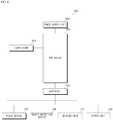
- FIG. 8 is a block diagram referred to for describing a lamp for vehicle according to an embodiment of the present invention.
- the vehicle 100 may include a lamp for vehicle 800.
- the lamp for vehicle 800 may include a laser diode 810, an interface 830, a controller 850, and a power supply unit 890.
- the lamp for vehicle 800 may further include a new component in addition to the components described in the present disclosure, or may not include some of the described components.
- the lamp for vehicle 800 may include a light collecting system for collecting light emitted from the laser diode 810 into a predetermined direction.
- the light collecting system may include multiple lenses and phosphors.
- the lamp for vehicle 800 is a headlamp of the vehicle 100
- the lamp for vehicle 800 may be any other type of lamp used in the vehicle 100, such as, for example, a fog lamp, a tail lamp, or a turn signal.
- the case in which the lamp for vehicle 800 is a headlamp will be described as a representative example.
- the lamp for vehicle 800 may be a pair of headlamps 800a and 800b provided on the left and right sides of the front of the vehicle 100.
- the lamp for vehicle 800 may output light to the region ahead of the vehicle 100.
- the laser diode 810 may be a diode that emits laser light, and may emit a predetermined wavelength of light.
- the laser diode 810 may emit various colors of light depending on the wavelength thereof.
- the laser diode 810 may be controlled so as to be turned on or off by supplying or interrupting power to the laser diode 810.
- the amount of light output from the laser diode 810 may be controlled by adjusting the voltage and/or current supplied to the laser diode 810.
- the laser diode 810 may be controlled so as to be turned off after being dimmed.
- the light output of the laser diode 810 may be controlled by the controller 850.
- the light output of the laser diode 810 may be controlled by the controller 850 based on brake operation information.
- the brake operation information may be information including at least one of whether or not a brake is operated, the force of operation of the brake, or the brake operation time.
- the light output of the laser diode 810 may be controlled by the controller 850 based on object information.
- the object information may be at least one of the distance between the vehicle 100 and an object, the speed of an object relative to the vehicle 100, the absolute speed of an object, the size of an object, the type of an object, whether or not an object is a living thing, or whether an object is a fixed object or a mobile object.
- the light output of the laser diode 810 may be controlled by the controller 850 based on an expected time to collision (TTC).
- TTC expected time to collision
- the expected time to collision may be a value that is a result of predicting the time remaining until the vehicle 100 collides with an object.
- the expected time to collision may be calculated by the processor 370 in the object detection device 300 based on the object information.
- the expected time to collision may be calculated by the controller 850 based on the distance between an object O and the vehicle 100, the speed of the object O relative to the vehicle 100, and the acceleration of the vehicle 100.
- the light output of the laser diode 810 may be controlled by the controller 850 based on whether or not an object is a living thing.
- the light output of the laser diode 810 may be controlled by the controller 850 based on vehicle shock information.
- the shock information may be information regarding whether or not the vehicle 100 receives shocks.
- the shock information may include information regarding whether there is a broken part of mechanisms provided in the vehicle 100 when the vehicle 100 receives shocks.
- the light output of the laser diode 810 may be controlled by the controller 850 based on shock position information.
- the shock position information may be information regarding the position at which the vehicle 100 receives shocks, and may be expressed in left/right/front/rear directions and combinations thereof.
- the shock position information is about the incidence of shocks applied to each mechanism provided in the vehicle 100.
- the light output of the laser diode 810 may be controlled by the controller 850 based on lamp information.
- the lamp information may include at least one of information regarding whether or not a lamp is damaged, or information regarding the output state of light emitted from a lamp.
- the light output of the laser diode 810 may be controlled by the controller 850 based on light output state information.
- the light output state information may include at least one of the pattern of light emitted from a lamp, the amount of light, the color of light, or variation in the output of light in response to a control signal.
- the controller 850 may perform a control operation to differentiate the light output of multiple laser diodes 810.
- the interface 830 may serve as paths to various types of external devices connected to the lamp for vehicle 800.
- the interface 830 may exchange information, signals, or data with other devices included in the vehicle 100.
- the interface 830 may transmit received information, signals, or data to the controller 850.
- the interface 830 may transmit information, signals, or data, produced or processed in the controller 850, to other devices included in the vehicle 100.
- the interface 830 may be the same as the interface 130.
- the interface 830 may be provided in the lamp for vehicle 800, separately from the interface 130.
- the interface 830 may serve as paths to various types of external devices connected to the vehicle 100.
- the controller 850 may provide overall control to each unit inside the lamp for vehicle 800.
- the controller 850 may be implemented using at least one of Application Specific Integrated Circuits (ASICs), Digital Signal Processors (DSPs), Digital Signal Processing Devices (DSPDs), Programmable Logic Device (PLDs), Field Programmable Gate Arrays (FPGAs), processors, controllers, microcontrollers, microprocessors, and electrical units for executing other functions.
- ASICs Application Specific Integrated Circuits
- DSPs Digital Signal Processors
- DSPDs Digital Signal Processing Devices
- PLDs Programmable Logic Device
- FPGAs Field Programmable Gate Arrays
- processors controllers, microcontrollers, microprocessors, and electrical units for executing other functions.
- the controller 850 may be the same as the controller 170 of the vehicle 100.
- the controller 850 may be provided in the lamp for vehicle 800, separately from the controller 170.
- a brake device 105 may be a device used to brake the vehicle 100, and may be driven by the brake driver 622.
- the brake driver 622 may control the brake device 105 upon receiving a signal from the brake input device 570.
- the brake device 105 may be controlled by an autonomous emergency braking system (AEBS).
- AEBS autonomous emergency braking system
- the brake driver 622 may control the brake device 105 upon receiving a signal from the autonomous emergency braking system.
- the controller 850 may receive brake operation information from the brake device 105 via the interface 830.
- the brake operation information may be information including at least one of whether or not a brake is operated, the force of operation of the brake, or the brake operation time.
- the controller 850 may receive the brake operation information from the brake device 105.
- the controller 850 may receive the brake operation information, which is produced in the brake driver 622 and is provided to the brake device 105, from the brake device 105.
- the controller 850 may receive the brake operation information from the brake driver 622.
- the controller 850 may receive the brake operation information from the brake input device 570.
- the controller 850 may receive the brake operation information, which is produced in the autonomous emergency braking system and is provided to the brake device 105, from the brake device 105.
- the controller 850 may receive the brake operation information from the autonomous emergency braking system.
- the controller 850 may control the light output of the laser diode 810 based on the brake operation information.
- the controller 850 may control at least one of the On/Off operation, the output amount of light, the output pattern of light, and the operation time of the laser diode 810 based on the brake operation information.
- the lamp for vehicle 800 provided as described above may control the laser diode 810 in advance before the lamp for vehicle 800 is damaged due to an accident, thereby preventing a laser, which may be very harmful to the visual system of a living thing, from being discharged outward from the lamp for vehicle 800.
- the controller 850 may control the laser diode 810 so as to be turned off when a full braking operation is determined, thereby preventing a laser from being discharged outward from the lamp for vehicle 800 when an accident occurs.
- the full braking operation may mean that a brake is operated with the maximum force.
- the full braking operation may mean that a brake is operated with the maximum force that the user can input.
- the controller 850 may control the laser diode 810 so as to be dimmed when it is determined that a braking operation is performed with a preset value or more of force.
- the preset value may be set to a value that is lower than the brake force upon a full braking operation.
- the controller 850 may control the laser diode 810 so as to be dimmed when it is determined that the brake force is equal to or greater than the preset value and is less than the maximum force.
- the controller 850 may control the brightness of the laser diode 810 so as to be reduced in inverse proportion when the brake force continuously increases to the preset value or more.
- the lamp for vehicle 800 provided as described above may control the laser diode 810 in advance before an accident occurs so that the laser diode 810 outputs light in a dimmed state for a predetermined period so as to secure the driver's view.
- the controller 850 may receive object information from the object detection device 300 via the interface 830.
- the controller 850 may control the light output of the laser diode 810 based on the object information.
- the object information may be information regarding at least one of the distance between the vehicle 100 and an object, the speed of an object relative to the vehicle 100, the absolute speed of an object, the size of an object, the type of an object, whether or not an object is a living thing, or whether an object is a fixed object or a mobile object.
- the controller 850 may determine the degree of danger with respect to each of one or more objects O based on object information.
- the controller 850 may control the laser diode 810 so as to be turned off at a longer distance to one object O, which is determined to have a high degree of danger, than a distance to another object O, which is determined to have a low degree of danger.
- the controller 850 may determine a dangerous object based on object information, and may control the sensing unit 120 so as to sense a dangerous object first.
- the controller 850 may receive object information including the expected time to collision (TTC) between the vehicle 100 and an object O.
- TTC expected time to collision
- the expected time to collision may be calculated by the processor 370 in the object detection device 300 based on the object information.
- the expected time to collision may be calculated by the controller 850 based on the object information including the distance between the object O and the vehicle 100, the speed of the object O relative to the vehicle 100, and the acceleration of the object O.
- the controller 850 may control the light output of the laser diode 810 based on the expected time to collision.
- the controller 850 may control the light output of the laser diode 810 based on the expected time to collision. In this case, the controller 850 may control the light output of the laser diode 810 based on the expected time to collision, instead of brake operation information.
- the controller 850 may control the laser diode 810 so as to be turned off before the expected time to collision arrives.
- the controller 850 may control the laser diode 810 so as to be turned off when the expected time to collision (TTC) is below a preset Off time T off .
- TTC expected time to collision
- the Off time T off may be a preset time.
- the Off time T off may be set based on object information.
- the Off time T off when the object O is a mobile object may be set to be longer than the Off time T off when the object O is a fixed object.
- the lamp for vehicle 800 configured as described above may control the laser diode 810 in advance before the lamp for vehicle 800 is damaged due to an accident, thereby preventing a laser, which may be very harmful to the visual system of a living thing, from being discharged outward from the lamp for vehicle 800.
- the controller 850 may control the laser diode 810 so as to be turned off after being dimmed.
- the controller 850 may control the laser diode 810 so as to be dimmed from a predetermined time before the expected time to collision (TCC) arrives.
- TCC expected time to collision
- the controller 850 may control the laser diode 810 so as to be dimmed when the expected time to collision TTC is equal to or greater than a preset Off time T off and less than a dimming time T dim .
- the dimming time T dim may be a preset time.
- the dimming time T dim may be set based on object information.
- the dimming time T dim when the object O is a mobile object may be set to be longer than the diming time T dim when the object O is a fixed object.
- the lamp for vehicle 800 configured as described above may control the laser diode 810 in advance before an accident occurs so that the laser diode 810 outputs light in a dimmed state for a predetermined period so as to secure the driver's view.
- the controller 850 may receive object information including whether or not the object O is a living thing.
- the controller 850 may control the light output of the laser diode 810 based on whether or not the object O is a living thing.
- the controller 850 may control the laser diode 810 so as to be dimmed to a greater amount when the object O is a living thing than that when the object O is not a living thing.
- the controller 850 may set the Off time Toff so as to be longer when the object O is a living thing than that when the object O is not a living thing.
- the controller 850 may control the laser diode 810 so as to be dimmed in response to a braking operation performed with a preset value or more of force.
- the controller 850 may keep the laser diode 810 in an On state, rather than being dimmed, even if a braking operation is performed with a preset value or more of force.
- the lamp for vehicle 800 provided as described above may control the laser diode 810 so as to prevent, for example, the visual system of a living thing from sustaining serious damage due to a laser, or to secure first the driver's view, when the object O is not a living thing.
- the controller 850 may control the light output of the laser diode 810 based on brake operation information of the autonomous emergency braking system.
- the controller 850 may receive the brake operation information from the autonomous emergency braking system.
- the controller 850 may control the light output of the laser diode 810 based on the received brake operation information.
- the controller 850 may control the laser diode 810 so as to be turned off earlier when the autonomous emergency braking system senses the object O, compared to the case in which no object O is sensed.
- the controller 850 may control the laser diode 810 so as to be turned off even if no brake operation is sensed. In this case, the vehicle 100 may be safely braked by the autonomous emergency braking system even if the user inputs no brake signal.
- the lamp for vehicle 800 provided as described above may effectively control the laser diode 810 in advance because the light output of the laser diode 810 is automatically controlled in connection with the autonomous emergency braking system.
- the controller 850 may receive shock information of the vehicle 100 from the sensing unit 120 via the interface 830.
- the shock information may be information regarding whether or not the vehicle 100 receives shocks.
- the shock information may include information regarding whether there is a broken part of mechanisms provided in the vehicle 100 when the vehicle 100 receives shocks.
- the shock information may be produced by the sensing unit 120, which includes a collision sensor capable of sensing a collision.
- the controller 850 may control the light output of the laser diode 810 based on the shock information of the vehicle 100.
- the controller 850 may control the laser diode 810 so as to be turned off when it is determined that the vehicle 100 receives shocks.
- the shock information of the vehicle 100 may include shock position information regarding the position at which the vehicle 100 receives shocks.
- the shock information is information regarding the position at which the vehicle 100 receives shocks, and the shock position information may be expressed in left/right/front/rear directions and combinations thereof.
- the shock position information may be about the incidence of shocks applied to each mechanism provided in the vehicle 100.
- the controller 850 may receive the shock position information from the sensing unit 120.
- the controller 850 may control the light output of the laser diode 810 based on the shock position information.
- the controller 850 may control the laser diode 810, which is disposed at the position at which the vehicle receives shocks, so as to be turned off when it is determined that the vehicle receives shocks.
- the controller 850 may control the laser diode 810 so as to be turned on when it is determined that the vehicle 100 receives no shock.
- the controller 850 may control the laser diode 810 so as to be turned on when it is determined that the vehicle 100 receives no shock, so as to secure the driver's view.
- the controller 850 may control the laser diode 810 so as to be kept in the Off state when it is determined that the vehicle 100 receives shocks, so as to prevent a laser from being discharged outward from the lamp for vehicle 800.
- the controller 850 may control the laser diode 810, which is disposed at a position at which the vehicle receives shocks, so as to be kept in the Off state, but may control the laser diode 810, which is disposed at a position at which the vehicle receives no shocks, so as to be turned on.
- the controller 850 may control the laser diode 810 so as to be turned on when it is determined that the vehicle 100 receives shocks, but the lamp for vehicle 800 including the laser diode 810 is normal.
- the controller 850 may receive lamp information from the sensing unit 120 via the interface 830.
- the lamp information may include at least one of information regarding whether or not a lamp is damaged, or information regarding the output state of light emitted from a lamp.
- the controller 850 may control the light output of the laser diode 810 based on the lamp information.
- the controller 850 may control the laser diode 810 provided in a corresponding lamp so as to be turned off.
- the controller 850 may control the laser diode 810 so as to be turned off when it is determined, as a result of comparing reference information with lamp information received from the sensing unit 120, that a lamp including the laser diode 810 is abnormal.
- the reference information may be lamp information of the laser diode 810, which is in the normal state, and may be calculated by the controller 850, based on a control signal provided from the controller 850 to the lamp for vehicle 800.
- the reference information may be pre-stored information in a memory.
- Whether or not a lamp including the laser diode 810 is normal may be determined by the controller 850 based on the fact that the difference between reference information and lamp information exceeds a threshold value, as a result of comparing the reference information with the lamp information received from the sensing unit 120.
- the controller 850 may receive the lamp information, including information on the output state of light emitted from the lamp for vehicle 800, from the camera 310 of the vehicle 100 via the interface 830.
- the controller 850 may control the light output of the laser diode 810 based on light output state information.
- the light output state information may include at least one of the pattern of light emitted from a lamp, the amount of light, the color of light, or variation in light output in response to a control signal.
- the light output state information may be generated using a camera provided in the sensing unit 120.
- the output state information of light emitted from a lamp may be generated using the camera provided in the sensing unit 120 by sensing an image of light emitted to the object O outside the vehicle.
- the controller 850 may control the laser diode 810 so as to be turned off when it is determined that a lamp is abnormal, as a result of comparing reference information with light output state information received from the sensing unit 120.
- the controller 850 may control the laser diode 810 so as to be turned off when the difference between reference information and lamp information exceeds a threshold value, as a result of comparing the preset reference information with light output state information received from the sensing unit 120.
- the controller 850 may control the laser diode 810 so as to be turned off when it is determined that the pattern of light emitted from the lamp for vehicle 800 is not the same as the pattern of light based on a produced control signal.
- Information regarding the pattern of light emitted from the lamp for vehicle 800 may be acquired from a pattern image of light emitted to an object on, for example, the road photographed by the camera provided in the sensing unit 120.
- the pattern of light based on the produced control signal may be calculated by the controller 850 based on a control signal provided from the controller 850 to the laser diode 810 for controlling the output of light.
- the pattern of light based on the produced control signal may be pre-stored information in the controller 850.
- Whether or not the pattern of light emitted from the lamp for vehicle 800 is the same as the pattern of light based on the produced control signal may be determined by the controller 850 based on whether or not the difference between the pattern of light emitted from the lamp for vehicle 800 and the pattern of light based on the produced control signal exceeds a threshold value.
- the lamp for vehicle 800 may determine whether or not a lamp is faulty, and when it is determined that a lamp is faulty, may turn off the laser diode 810 of the lamp, thereby reducing the risk of a laser being discharged outward from the lamp.
- the controller 850 may control the laser diode 810 so as to be turned off when variation in the output of light emitted from the lamp for vehicle 800 is not the same as variation in the output of light based on a produced control signal.
- Variation in the output of light may mean variation over time in at least one of the pattern, amount, or color of light emitted from the lamp for vehicle 800.
- Information regarding variation in the output of light emitted from the lamp for vehicle 800 may be produced using the camera provided in the sensing unit 120 by sensing an image of light emitted to the object O outside the vehicle.
- Variation in the output of light based on the produced control signal may be calculated by the controller 850 based on a control signal provided from the controller 850 to the laser diode 810 for controlling the output of light.
- the controller 850 may control the laser diode 810 so as to be turned off when it is determined that the output of light emitted from the lamp for vehicle 800 does not correspond to that in the on state even though the laser diode 810 switches from the Off state to the On state.
- the controller 850 may control the laser diode 810 so as to be turned off when it is determined that variation in the amount of light emitted from the lamp for vehicle 800 is not the same as variation in the amount of light based on the produced control signal.
- the controller 850 may control the laser diode 810 so as to be turned off when it is determined that the difference between variation in the amount of light emitted from the lamp for vehicle 800 and variation in the amount of light based on the produced control signal exceeds a threshold value.
- the controller 850 may control multiple laser diodes 810 differently.
- the controller 850 may control the multiple laser diodes 810 differently based on information regarding an object O.
- the controller 850 may control the multiple laser diodes 810, which are provided respectively in multiple lamp for vehicles 800, differently.
- the controller 850 may control a laser diode 810, which is provided on the front of the vehicle 100, and a laser diode 810, which is provided on the rear of the vehicle, differently.
- the lamp for vehicle 800 provided as described above may prevent in advance the risk of a laser being discharged outward from the lamp for vehicle 800 when an accident occurs and furthermore may secure the driver's view.
- the controller 850 may control multiple laser diodes 810 provided in the lamp for vehicle 800 differently.
- the controller 850 may control the laser diode 810, which is determined to be abnormal, so as to be turned off, and may control the laser diode 810, which is determined to be normal, so as to be turned on.
- the lamp for vehicle 800 provided as described above may control multiple laser diodes 810 differently based on whether or not the laser diodes 810 are abnormal, thereby preventing a laser from being discharged outward from the lamp and effectively securing the driver's view.
- the controller 850 may control an auxiliary light source so as to be turned on when controlling the laser diode 810 so as to be turned off.
- the auxiliary light source may be configured to emit light other than a laser, and may include a light output element.
- the auxiliary light source may be, for example, a light emitting diode (LED).
- LED light emitting diode
- the controller 850 configured as described above may secure the driver's view using the auxiliary light source when it becomes difficult for the driver to secure the view because the laser diode 810 is controlled so as to be turned off.
- the controller 850 may control the interface 830 so as to transmit a signal for causing the vehicle output unit 250 to generate an alarm when the laser diode 810 is controlled so as to be turned off.
- the controller 850 provided as described above may inform the user, such as the driver, about the turning off of the laser diode 810 in advance, thereby minimizing the user inconvenience.
- the power supply unit 890 may supply power required for the operation of respective components under the control of the controller 850.
- the power supply unit 890 may receive power from, for example, a battery inside the vehicle 100.
- the power supply unit 890 may be the power supply unit 190.
- the power supply unit 890 may be provided inside an operation assistance system, separately from the power supply unit 190.
- FIG. 9 is a flowchart illustrating the operation of the lamp for vehicle according to an embodiment of the present invention.
- the controller 850 may receive brake operation information from the brake device 105 via the interface 830 (S910) .
- the brake operation information may be information including at least one of whether or not a brake is operated, the force of operation of a brake, or the brake operation time.
- the controller 850 may receive object information from the object detection device 300 via the interface 830 (S920).
- the object information may be information regarding at least one of the distance between the vehicle 100 and an object, the speed of an object relative to the vehicle 100, the absolute speed of an object, the size of an object, the type of an object, whether or not an object is a living thing, or whether an object is a fixed object or a mobile object.
- the object information may include the expected time to collision (TTC) between the vehicle 100 and an object O.
- TTC expected time to collision
- the controller 850 may receive shock information of the vehicle 100 from the sensing unit 120 via the interface 830 (S930) .
- the shock information may be information regarding whether or not the vehicle 100 receives shocks.
- the shock information may include information regarding whether there is a broken part of mechanisms provided in the vehicle 100 when the vehicle 100 receives shocks.
- the shock position information may include shock position information regarding the position at which the vehicle 100 receives shocks.
- the controller 850 may receive lamp information from the sensing unit 120 via the interface 830 (S940).
- the lamp information may include at least one of information regarding whether or not a lamp is damaged, or information regarding the output state of light emitted from a lamp.
- the light output state information may include at least one of the pattern of light emitted from a lamp, the amount of light, the color of light, or variation in light output in response to a control signal.
- the controller 850 may control the light output of the laser diode 810 based on the brake operation information (S950) .
- the controller 850 may also control the light output of the laser diode 810 based on the object information.
- the controller 850 may also control the light output of the laser diode 810 based on the shock information of the vehicle 100.
- the controller 850 may also control the light output of the laser diode 810 based on the lamp information.
- the controller 850 may control an auxiliary light source so as to be turned on when the laser diode 810 is controlled so as to be turned off (S960).
- the controller 850 may control the interface 830 so as to transmit a signal to the vehicle output unit 250 for generating an alarm when the laser diode 810 is controlled so as to be turned off (S970).
- FIGs. 10A, 10B and 10C are views referred to for describing the operation of the lamp for vehicle when braking is sensed according to an embodiment of the present invention.
- the controller 850 may receive brake operation information from the brake device 105 via the interface 830.
- the controller 850 may control the light output of the laser diode 810 based on the brake operation information.
- the brake operation information may be information including at least one of whether or not a brake is operated, the force of operation of a brake, or the brake operation time.
- the brake operation information may be information, which is generated in the brake driver 622 in response to an input to the brake input device 570 and is provided to the brake device 105.
- the brake operation information may be information, which is generated in the automatic emergency braking device and provided to the brake device 105.
- the controller 850 may control the laser diode 810 so that light A1031 is output from a left lamp for vehicle 800a and light A1032 is output from a right lamp for vehicle 800b.
- the controller 850 may control the laser diode 810 so that the amounts of light A1041 and A1042 output from the lamp for vehicles 800a and 800b are reduced.
- the controller 850 may control the laser diode 810 so that the lamp for vehicles 800a and 800b are turned off.
- controller 850 may differently control the amount of dimming of the laser diode 810 based on the type of the object O.
- the controller 850 may control the laser diode 810 so as to be dimmed to a greater amount when the light emitted from the lamp for vehicle 800 illuminates a pedestrian OB12 than that when the light emitted from the lamp for vehicle 800 illuminates a vehicle OB11.
- the lamp for vehicle 800 provided as described above may control the laser diode 810 in advance before the lamp for vehicle 800 is damaged due to an accident, thereby preventing a laser, which may be very harmful to the visual system of a living thing, from being discharged outward from the lamp for vehicle 800.
- FIGs. 11A, 11B and 11C are views referred to for describing the operation of the lamp for vehicle depending on an expected collision time according to an embodiment of the present invention.
- the controller 850 may receive object information from the object detection device 300 via the interface 830.
- the object information may include the expected time to collision (TTC) between the vehicle 100 and an object OB1111.
- TTC expected time to collision
- the controller 850 may control the light output of the laser diode 810 based on the expected time to collision.
- the controller 850 may control the laser diode 810 so that light A1131 is output from the left lamp for vehicle 800a and light A1132 is output from the right lamp for vehicle 800b.
- the controller 850 may control the laser diode 810 so that the amounts of light A1141 and A1142 output from the lamp for vehicles 800a and 800b are reduced.
- the Off time T off may be a preset time.
- the Off time T off may be set based on object information.
- the Off time T off when the object O is a mobile object may be set to be longer than the Off time T off when the object O is a fixed object.
- the Off time T off when the object O is a living thing may be set to be longer than the Off time T off when the object O is an inanimate object.
- the dimming time T dim may be a preset time.
- the dimming time T dim may be set based on object information.
- the dimming time T dim when the object O is a mobile object may be set to be longer than the diming time T dim when the object O is a fixed object.
- the dimming time T dim when the object O is a living thing may be set to be longer than the diming time T dim when the object O is an inanimate object.
- the controller 850 may control the laser diode 810 so that the lamp for vehicles 800a and 800b are turned off.
- the controller 850 may control the laser diode 810 so as to be gradually dimmed within a period during which the expected time to collision is less than 7 seconds and is equal to or greater than 2 seconds, and thereafter may control the laser diode 810 so as to be turned off when the expected time to collision is less than 2 seconds.
- the lamp for vehicle 800 provided as described above may control the laser diode 810 in advance before the lamp for vehicle 800 is damaged due to an accident, thereby preventing a laser, which may be very harmful to the visual system of a living thing, from being discharged outward from the lamp for vehicle 800.
- FIGs. 12A and 12B are views referred to for describing the operation of the lamp for vehicle depending on the types of objects according to an embodiment of the present invention.
- the controller 850 may receive brake operation information from the brake device 105 via the interface 830.
- the brake operation information may be information including at least one of whether or not a brake is operated, the force of operation of a brake, or the brake operation time.
- the controller 850 may receive object information from the object detection device 300 via the interface 830.
- the object information may include information regarding whether or not the object O is a living thing.
- the controller 850 may control the light output of the laser diode 810 based on the brake operation information.
- the controller 850 may also control the light output of the laser diode 810 based on whether or not the object O is a living thing.
- the controller 850 may control the laser diode 810 so that the amounts of light A1231 and A1232 output from the lamps 800a and 800b are reduced.
- the controller 850 may set the amount of dimming of the laser diode 810 based on information regarding the distance to the pedestrian OB1211.
- the controller 850 may control the laser diode 810 so that the amounts of light A1241 and A1242 output from the lamps 800a and 800b are maintained, rather than being reduced.
- the controller 850 may control the laser diode 810 so as not to be dimmed even if a braking operation is performed with a preset value or more of force, and may control the laser diode 810 so as to be turned off when a full braking operation is performed.
- the lamp for vehicle 800 provided as described above may prevent, for example, the visual system of a living thing from sustaining serious damage due to a laser, but may control the laser diode 810 so as to secure first the driver's view when the object is not a living thing.
- FIGs. 13A and 13B are views referred to for describing the operation of the lamp for vehicle upon automatic emergency braking according to an embodiment of the present invention.
- the controller 850 may receive brake operation information from the brake device 105 via the interface 830.
- the brake operation information may be produced in an autonomous emergency braking system and may be provided to the brake device 105.
- the controller 850 may control the light output of the laser diode 810 based on the brake operation information.
- the controller 850 may also control the light output of the laser diode 810 based on brake operation information A1351 of the autonomous emergency braking system.
- the controller 850 may control the laser diode 810 differently when the autonomous emergency braking system senses an object O and when the autonomous emergency braking system senses no object O.
- the controller 850 may control the laser diode 810 so as to be turned off.
- the controller 850 may control the laser diode 810 so as to be dimmed.
- the controller 850 may control the laser diode 810 so as to be dimmed to a greater amount in the case A1351 in which the autonomous emergency braking system senses an object O than in the case where the autonomous emergency braking system senses no object O.
- the lamp for vehicle 800 configured as described above may more safely control the laser diode 810 when the autonomous emergency braking system secures safe braking.
- FIGs. 14A, 14B , 14C and 14D are views referred to for describing the operation of the lamp for vehicle when no collision is sensed after turn-off control according to an embodiment of the present invention.
- the controller 850 may receive brake operation information from the brake device 105 via the interface 830.
- the brake operation information may be produced in an autonomous emergency braking system and may be provided to the brake device 105.
- the controller 850 may receive shock information of the vehicle 100 from the sensing unit 120 via the interface 830.
- the shock information may be information regarding whether or not the vehicle 100 receives shocks.
- the controller 850 may control the light output of the laser diode 810 based on the brake operation information.
- the controller 850 may also control the light output of the laser diode 810 based on the shock information of the vehicle 100.
- the controller 850 may control the laser diode 810 so that the lamps 800a and 800b emit light A1421 and A1422.
- the controller 850 may control the laser diode 810 so as to be turned off.
- FIG. 14C illustrates the case in which the vehicle 100 stops without colliding with another vehicle OB1411.
- the controller 850 may control the laser diode 810 so as to be turned on.
- the controller 850 may also control the laser diode 810 based on object information.
- the controller 850 may control the laser diode 810 so as to be turned on and dimmed.
- the controller 850 may control the laser diode 810 so as to be turned on and dimmed.
- the controller 850 may control the laser diode 810 so as to be kept in the Off state.
- the lamp for vehicle 800 configured as described above may control the laser diode 810 so as to rapidly secure the driver's view when there is no risk of a laser being directly discharged outwards.
- FIGs. 15A, 15B , 15C and 15C are views referred to for describing the operation of the lamp for vehicle when a collision is sensed after turn-off control according to an embodiment of the present invention.
- the controller 850 may receive brake operation information from the brake device 105 via the interface 830.
- the brake operation information may be produced in an autonomous emergency braking system and may be provided to the brake device 105.
- the controller 850 may receive shock information of the vehicle 100 from the sensing unit 120 via the interface 830.
- the shock information may be information regarding whether or not the vehicle 100 receives shocks.
- the shock information may include shock position information regarding the position at which the vehicle 100 receives shocks.
- the controller 850 may control the light output of the laser diode 810 based on the brake operation information.
- the controller 850 may also control the light output of the laser diode 810 based on the shock information of the vehicle 100.
- the controller 850 may control the laser diode 810 so that the lamps 800a and 800b emit light A1521 and A1522.
- the controller 850 may control the laser diode 810 so as to be turned off.
- FIG. 15C illustrates the case in which a collision between the vehicle 100 and another vehicle OB1511 occurs, and illustrates a collision C between the left front side of the vehicle 100 and the rear side of the other vehicle OB1511.
- the controller 850 may control the laser diode 810 based on the shock information received from the sensing unit 120 so that the left lamp for vehicle 800a, which is determined to be receiving shocks, is kept in the Off state and so that the right lamp for vehicle 800b, which is determined not to be receiving shocks, is turned on so as to emit light A1531.
- the lamp for vehicle 800 configured as described above may control the laser diode 810 so that the lamp 800, which is not damaged even when the vehicle 100 receives shocks, is rapidly turned on so as to rapidly secure the driver's view.
- FIGs. 16A and 16B are views referred to for describing the operation of the lamp for vehicle depending on optical patterns according to an embodiment of the present invention.
- the controller 850 may receive lamp information from the sensing unit 120 via the interface 830.
- the lamp information may include at least one of information regarding whether or not a lamp is damaged, or information regarding the output state of light emitted from a lamp.
- the light output state information may include at least one of the pattern of light emitted from a lamp, the amount of light, the color of light, or variation in light output in response to a control signal.
- FIG. 16A illustrates patterns A1521 and A1522 of light emitted from the lamp for vehicle 800, which is normal, to a road OB1610.
- the controller 850 may receive, from the sensing unit 120, information regarding patterns A1621 and A1622 of light emitted from the lamp for vehicles 800a and 800b to a road
- the controller 850 may control the laser diode 810 so as to be turned off when it is determined that patterns A1631 and A1632 of light emitted from the lamp for vehicle 800 are not the same as the patterns A1621 and A1622 of light based on a produced control signal.
- the patterns A1631 and A1632 of light emitted from the lamp for vehicle 800 are patterns of light emitted to an actual road OB1610 as information received from the sensing unit 120.
- the patterns A1621 and A1622 of light based on the produced control signal may be calculated by the controller 850 based on a control signal provided from the controller 850 to the laser diode 810 in order to control the light output.
- the patterns A1621 and A1622 of light based on the produced control signal may be pre-stored information in the controller 850.
- the patterns A1621 and A1622 of light based on the produced control signal may be pre-stored information regarding the patterns A1521 and A1522 of light emitted from the lamp for vehicle 800, which is normal, to the road OB1610 in a memory.
- the controller 850 may compare the patterns A1631 and A1632 of light emitted from the lamp for vehicle 800 with the patterns A1621 and A1622 of light based on the produced control signal, and may control the laser diode 810 of the left lamp for vehicle 800a so as to be turned off when it is determined that the difference therebetween exceeds a threshold value.
- the controller 850 may compare the patterns A1631 and A1632 of light emitted from the lamp for vehicle 800 with the patterns A1621 and A1622 of light based on the produced control signal with respect to at least one of the amount of light, the color of light, or variation in the output of light in response to a control signal, and may control the laser diode 810 of the left lamp for vehicle 800a so as to be turned off when it is determined that the difference therebetween exceeds a threshold value.
- the lamp for vehicle 800 may determine whether or not the lamp is faulty, and may turn off the laser diode 810 of the lamp when it is determined that the lamp is faulty, thereby reducing the risk of a laser being discharged outward from the lamp.
- FIG. 17 is a view referred to for describing the control of multiple laser diodes in the lamp for vehicle according to an embodiment of the present invention.
- the controller 850 may receive brake operation information from the brake device 105 via the interface 830.
- the brake operation information may be produced in an autonomous emergency braking system and may be provided to the brake device 105.
- the controller 850 may receive object information from the object detection device 300 via the interface 830.
- the object information may be information regarding at least one of the distance between the vehicle 100 and an object, the speed of an object relative to the vehicle 100, the absolute speed of an object, the size of an object, the type of an object, whether or not an object is a living thing, or whether an object is a fixed object or a mobile object.
- the controller 850 may control the light output of the laser diode 810 based on the brake operation information.
- the controller 850 may also control the light output of the laser diode 810 based on the object information.
- the controller 850 may control multiple laser diodes 810 differently.
- the multiple laser diodes 810 may be respectively provided in multiple lamp for vehicles 800.
- the controller 850 may control the laser diode 810 so that only the lamp for vehicle 800b, which emits light toward an object OB1711, among the multiple lamp for vehicles 800a and 800b is dimmed.
- the controller 850 may control the laser diode 810 so that only the lamp for vehicle 800, which is at the position at which the vehicle 100 receives shocks, among multiple lamp for vehicles 800, is turned off.
- the controller 850 may control the laser diode 810 so that only the lamp for vehicle 800, which is determined to be abnormal, among multiple lamp for vehicles 800 is turned off, based on lamp information received from the sensing unit 120.
- the lamp for vehicle 800 configured as described above may safely control the multiple laser diodes 810 so as to secure the driver's view effectively.
- the invention described above may be realized as a computer-readable code in a medium in which programs are recorded.
- the computer-readable medium includes all types of recording device in which data, which may be read by a computer system, are stored. Examples of the computer-readable medium may include a hard disk drive (HDD), solid state disk (SSD), silicon disk drive (SDD), ROM, RAM, CD-ROM, magnetic tape, floppy disc, or optical data storage device.
- the computer-readable medium may be realized in a carrier wave (e.g., transmission via the Internet).
- the computer may include the controller 180 of the terminal.
Landscapes
- Engineering & Computer Science (AREA)
- Mechanical Engineering (AREA)
- Physics & Mathematics (AREA)
- General Engineering & Computer Science (AREA)
- Optics & Photonics (AREA)
- Condensed Matter Physics & Semiconductors (AREA)
- General Physics & Mathematics (AREA)
- Electromagnetism (AREA)
- Lighting Device Outwards From Vehicle And Optical Signal (AREA)
- Traffic Control Systems (AREA)
Abstract
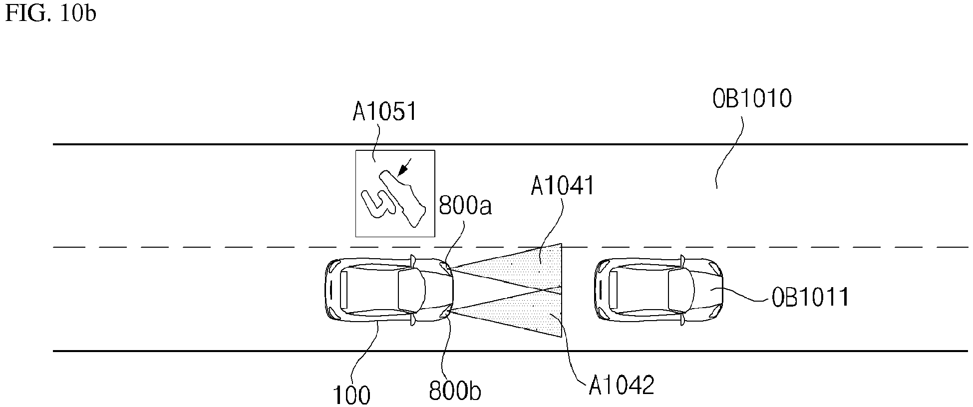
Description
- This application claims the priority benefit of Korean Patent Application No.
10-2017-0103750, filed on Aug 16, 2017 - The present invention relates to a lamp for vehicle having a laser light source.
- A vehicle refers to a device that carries a passenger in a passenger-intended direction. A car is a major example of the vehicle.
- To increase the convenience of vehicle users, a vehicle is equipped with various sensors, electronic devices and the like. In particular, an Advanced Driver Assistance System (ADAS) and an autonomous vehicle are under active study to increase the driving convenience of users.
- In recent years, the use of a laser light source in a vehicle has become important. Such a laser light source has a size smaller than that of a conventional light source such as an LED, and thus advantageously may have high utilization efficiency and may increase the density of light output from a lamp.
- A laser diode (LD) used for a vehicle headlamp is several watts, but animals' eyes, including humans' eyes, may be seriously damaged even if they are exposed to a laser of only 2 mW or more. Therefore, in order to protect the eyes of people and other living things, a lamp for vehicle does not directly radiate a laser beam, but converts and uses the laser beam. For example, as a headlamp using a laser light source, there is one that converts blue light into white light using an intermediate medium including phosphors when in use.
- However, when the laser lamp is damaged due to, for example, the shock of an accident, the laser beam may be directly exposed to the outside of the lamp. Therefore, there is demand for a method of controlling the laser lamp in order to prevent damage to the eyes of people and living things due to the laser beam.
- An object of embodiments of the present invention is to safely control a laser lamp before an accident occurs, in order to prevent a laser beam, which may very harmful to the visual system of a living thing, from being discharged to the outside of the lamp.
- In addition, an object of embodiments of the present invention is to safely control a laser lamp before an accident occurs and to secure the driver's view effectively.
- In addition, an object of embodiments of the present invention is to enable a laser lamp to be used safely and effectively through control after the laser lamp is controlled so as to be turned off.
- In addition, an object of embodiments of the present invention is to minimize the inconvenience of a user such as, for example, a driver, while safely controlling a laser lamp.
- The objects of the present invention are not limited to the objects as mentioned above, and other unmentioned objects will be clearly understood by those skilled in the art from the following description. The aforementioned objects are achieved by the independent claim. Dependent claims refer to preferred embodiments.
- In accordance with an aspect of the present invention, a lamp for vehicle includes a laser diode, an interface, and a controller. The controller is configured to receive brake operation information from a brake device via the interface. The controller is configured to control a light output of the laser diode based on the brake operation information.
- The controller may control the laser diode so as to be turned off when it is determined that a full braking operation is performed.
- The controller may control the laser diode so as to be dimmed when it is determined that a braking operation is performed with a preset value or more of force.
- The controller may receive the object information including whether or not an object is a living thing. The controller may also control the light output of the laser diode based on whether or not the object is the living thing.
- The controller may receive vehicle shock information from a sensing unit via the interface. The controller may control the laser diode so as to be turned on when it is determined that a vehicle receives no shock in a state in which the laser diode is turned off.
- The present invention also relates to a lamp for a vehicle comprising at least one laser diode configured to output light; at least one controller configured to receive a signal comprising brake operation information, and based on the signal comprising brake operation information, generate a signal to control on/off or a light intensity of the at least one laser diode.
- Preferably, the at least one controller is further configured to when a signal indicating a full braking operation is received, generate a signal to control the at least one laser diode to be turned off.
- Preferably, the at least one controller is further configured to, when a signal indicating that a braking operation is performed with a preset value of force or more is received, generate a signal to control the at least one laser diode to reduce the light intensity.
- Preferably, the at least one controller is further configured to receive a signal comprising object information.
- Preferably, the at least one controller is further configured to generate a signal to control on/off or the light intensity of the at least one laser diode based on the signal comprising object information.
- Preferably, the object information includes an expected time to collision, TTC, between the vehicle and an object.
- Preferably, the at least one controller is further configured to generate a signal to control on/off or the light intensity of the at least one laser diode based on the signal comprising information on TTC.
- Preferably, the at least one controller is further configured to generate a signal to control the at least one laser diode to be turned off before the TTC is exceeded.
- Preferably, the at least one controller is further configured to generate a signal to control the at least one laser diode to be turned off after being dimmed.
- Preferably, the object information includes information on whether an object is a living object.
- Preferably, the at least one controller is further configured to based on the signal comprising information whether an object is a living object, generate a signal to control on/off or the light intensity of the at least one laser diode.
- Preferably, the vehicle further comprises an autonomous emergency braking system, AEBS.
- Preferably, the at least one controller is further configured to generate a signal to control on/off or the light intensity of the at least one laser diode based on the signal about brake operation generated from the AEBS.
- Preferably, the at least one controller is further configured to receive a signal comprising vehicle shock information.
- Preferably, the at least one controller is further configured to generate a signal to control on/off or the light intensity of the at least one laser diode based on the signal comprising vehicle shock information.
- Preferably, the vehicle shock information includes shock position information regarding a position at which the vehicle receives a shock.
- Preferably, the at least one controller is further configured to generate a signal to control on/off or the light intensity of the at least one laser diode based on the signal comprising shock position information.
- Preferably, in a state in which the at least one laser diode is turned off, the at least one controller is further configured to generate a signal to control the at least one laser diode to be turned on when a signal indicating that the vehicle receives no shock is received.
- Preferably, the at least one controller is further configured to receive a signal comprising lamp information received from a sensing unit.
- Preferably, the at least one controller is further configured to, based on the signal comprising lamp information, generate a signal to control on/off or the light intensity of the at least one laser diode.
- Preferably, the lamp information includes information on a state of light output emitted from the lamp.
- Preferably, the at least one controller is further configured to based on the signal comprising information on the state of light output, generate a signal to control on/off or the light intensity of the at least one laser diode.
- Preferably, the at least one controller is further configured to, when a detected pattern of light emitted from the lamp deviates from an expected pattern of light based on a control signal produced by the at least one controller, generate a signal to control the at least one laser diode to be turned off.
- Preferably, the at least one controller is further configured to, when detected variation in an output of light emitted from the lamp deviates from expected variation in an output of light based on a control signal produced by the at least one controller, generate a signal to control the at least one laser diode to be turned off.
- Preferably, the at least one controller is further configured to generate a signal to control the at least one laser diode individually.
- Preferably, the at least one controller is further configured to, when the laser diode is controlled to be turned off, generate a signal to an output unit of the vehicle, the output unit being configured to, in response to reception of the signal from the at least one controller, generate an alarm.
- Concrete details of other embodiments are included in the detailed description and the drawings.
- The above and other objects, features and other advantages of the present invention will be more clearly understood from the following detailed description taken in conjunction with the accompanying drawings, in which:
-
FIG. 1 is a view illustrating the exterior of a vehicle according to an embodiment of the present invention; -
FIG. 2 is a view illustrating exteriors of a vehicle, seen at various angles from the outside of the vehicle according to an embodiment of the present invention; -
FIGs. 3 and4 are views illustrating interiors of a vehicle according to an embodiment of the present invention; -
FIGs. 5 and6 are views referred to for describing objects according to an embodiment of the present invention; -
FIG. 7 is a block diagram referred to for describing a vehicle according to an embodiment of the present invention; -
FIG. 8 is a block diagram referred to for describing a lamp for vehicle according to an embodiment of the present invention; -
FIG. 9 is a flowchart illustrating the operation of the lamp for vehicle according to an embodiment of the present invention; -
FIGs. 10A, 10B and10C are views referred to for describing the operation of the lamp for vehicle when braking is sensed according to an embodiment of the present invention; -
FIGs. 11A, 11B and11C are views referred to for describing the operation of the lamp for vehicle depending on an expected time to collision (TTC) according to an embodiment of the present invention; -
FIGs. 12A and 12B are views referred to for describing the operation of the lamp for vehicle depending on the types of objects according to an embodiment of the present invention; -
FIGs. 13A and 13B are views referred to for describing the operation of the lamp for vehicle upon automatic emergency braking according to an embodiment of the present invention; -
FIGs. 14A, 14B ,14C and 14D are views referred to for describing the operation of the lamp for vehicle when no collision is sensed after turn-off control according to an embodiment of the present invention; -
FIGs. 15A, 15B ,15C and 15C are views referred to for describing the operation of the lamp for vehicle when a collision is sensed after turn-off control according to an embodiment of the present invention; -
FIGs. 16A and 16B are views referred to for describing an operation of the lamp for vehicle depending on optical patterns according to an embodiment of the present invention; and -
FIG. 17 is a view referred to for describing the control of multiple laser diodes in the lamp for vehicle according to an embodiment of the present invention. - Embodiments disclosed in the present disclosure will be described in detail with reference to the attached drawings. Like reference numerals denote the same or similar components throughout the drawings and a redundant description of the same components will be avoided. The terms with which the names of components are suffixed, 'module' and 'unit' are assigned or interchangeably used with each other, only in consideration of the readiness of specification writing. The terms do not have any distinguishable meanings or roles. A detailed description of a related known technology will be omitted lest it should obscure the subject matter of embodiments of the present disclosure. Further, the attached drawings are provided to help easy understanding of embodiments disclosed in the present disclosure, not limiting the scope and spirit of the present disclosure. Thus, it is to be understood that the present disclosure covers all modifications, equivalents, and/or alternatives falling within the scope and spirit of the present disclosure.
- While ordinal numbers including 'first', 'second', etc. may be used to describe various components, they are not intended to limit the components. These expressions may be used to distinguish one component from another component.
- When it is said that a component is 'coupled with/to' or 'connected to' another component, it should be understood that the one component is connected to the other component directly or through any other component in between. On the other hand, when it is said that a component is 'directly connected to' or 'directly coupled to' another component, it should be understood that there is no other component between the components.
- Singular forms include plural referents unless the context clearly dictates otherwise.
- In the present disclosure, the term 'have', 'may have', 'include', or 'may include' signifies the presence of a specific feature, number, step, operation, component, or part, or their combinations, not excluding the presence or addition of one or more other features, numbers, steps, operations, components, or parts, or their combinations.
- The term 'vehicle' used in the present disclosure may cover a car and a motorbike in concept. The following description is given with the appreciation that a vehicle is a car, by way of example.
- In the present disclosure, a vehicle may be any of an internal combustion vehicle equipped with an engine as a power source, a hybrid vehicle equipped with an engine and an electrical motor as power sources, an electric vehicle equipped with an electrical motor as a power source, and the like.
- In the following description, the left of a vehicle means the left of a driving direction of the vehicle, and the right of the vehicle means the right of the driving direction of the vehicle.
-
FIG. 1 is a view illustrating the exterior of a vehicle according to an embodiment of the present invention. -
FIG. 2 is a view illustrating exteriors of a vehicle, seen at various angles from the outside of the vehicle according to an embodiment of the present invention. -
FIGs. 3 and4 are views illustrating interiors of a vehicle according to an embodiment of the present invention. -
FIGs. 5 and6 are views referred to for describing objects according to an embodiment of the present invention. -
FIG. 7 is a block diagram of a vehicle according to an embodiment of the present invention. - Referring to
FIGs. 1 to 7 , avehicle 100 may include wheels rotated by a power source, and asteering input device 510 for controlling a heading direction of thevehicle 100. - The
vehicle 100 may be an autonomous vehicle. - The
vehicle 100 may switch to an autonomous driving mode or a manual mode based on a user input. - For example, the
vehicle 100 may switch from the manual mode to the autonomous driving mode or from the autonomous driving mode to the manual mode, based on a user input received through a User Interface (UI)device 200. - The
vehicle 100 may switch to the autonomous driving mode or the manual mode based on driving situation information. - The driving situation information may include at least one of information on objects outside the
vehicle 100, navigation information, or vehicle state information. - For example, the
vehicle 100 may switch from the manual mode to the autonomous driving mode or from the autonomous driving mode to the manual mode, based on driving situation information generated from anobject detection device 300. - For example, the
vehicle 100 may switch from the manual mode to the autonomous driving mode or from the autonomous driving mode to the manual mode, based on driving situation information received through acommunication device 400. - The
vehicle 100 may switch from the manual mode to the autonomous driving mode or from the autonomous driving mode to the manual mode, based on information, data, or signals provided from external devices. - When the
vehicle 100 drives in the autonomous driving mode, theautonomous vehicle 100 may drive based on anoperation system 700. - For example, the
autonomous vehicle 100 may drive based on information, data, or signals generated from adriving system 710, a park-outsystem 740, and a park-insystem 750. - When the
vehicle 100 drives in the manual mode, theautonomous vehicle 100 may receive a user input for driving through amaneuvering device 500. Thevehicle 100 may drive based on the user input received through themaneuvering device 500. - An overall length refers to a length from the front side to the rear side of the
vehicle 100, an overall width refers to a width of thevehicle 100, and an overall height refers to a length from the bottom of a wheel to the roof of thevehicle 100. In the following description, an overall length direction L may refer to a direction based on which the overall length of thevehicle 100 is measured, an overall width direction W may refer to a direction based on which the overall width of thevehicle 100 is measured, and an overall height direction H may refer to a direction based on which the overall height of thevehicle 100 is measured. - Referring to
FIG. 7 , thevehicle 100 may include theuser interface device 200, theobject detection device 300, thecommunication device 400, themaneuvering device 500, avehicle driving device 600, theoperation system 700, anavigation system 770, asensing unit 120, aninterface 130, amemory 140, acontroller 170, apower supply unit 190, and a lamp forvehicle 800. - According to an embodiment, the
vehicle 100 may further include a new component in addition to the components described in the present disclosure, or may not include some of the described components. - The
user interface device 200 is a device used to enable thevehicle 100 to communicate with a user. Theuser interface device 200 may receive a user input, and provide information generated from thevehicle 100 to the user. Thevehicle 100 may implement UIs or User Experience (UX) through theuser interface device 200. - The
user interface device 200 may include aninput unit 210, aninternal camera 220, abiometric sensing unit 230, anoutput unit 250, and aprocessor 270. - According to an embodiment, the
user interface device 200 may further include a new component in addition to components described below, or may not include some of the described components. - The
input unit 210 is intended to receive information from a user. Data collected by theinput unit 210 may be analyzed and processed as a control command from the user by theprocessor 270. - The
input unit 210 may be disposed inside thevehicle 100. For example, theinput unit 210 may be disposed in an area of a steering wheel, an area of an instrument panel, an area of a seat, an area of each pillar, an area of a door, an area of a center console, an area of a head lining, an area of a sun visor, an area of a windshield, an area of a window, or the like. - The
input unit 210 may include avoice input unit 211, agesture input unit 212, atouch input unit 213, and amechanical input unit 214. - The
voice input unit 211 may convert a voice input of the user to an electrical signal. The electrical signal may be provided to theprocessor 270 or thecontroller 170. - The
voice input unit 211 may include one or more microphones. - The
gesture input unit 212 may convert a gesture input of the user to an electrical signal. The electrical signal may be provided to theprocessor 270 or thecontroller 170. - The
gesture input unit 212 may include at least one of an InfraRed (IR) sensor or an image sensor, for sensing a gesture input of the user. - According to an embodiment, the
gesture input unit 212 may sense a Three-Dimensional (3D) gesture input of the user. To this end, thegesture input unit 212 may include a light output unit for emitting multiple IR rays or multiple image sensors. - The
gesture input unit 212 may sense a 3D gesture input of the user by Time of Flight (ToF), structured light, or disparity. - The
touch input unit 213 may convert a touch input of the user to an electrical signal. The electrical signal may be provided to theprocessor 270 or thecontroller 170. - The
touch input unit 213 may include a touch sensor for sensing a touch input of the user. - According to an embodiment, a touch screen may be configured by integrating the
touch input unit 213 with adisplay unit 251. This touch screen may provide both an input interface and an output interface between thevehicle 100 and the user. - The
mechanical input unit 214 may include at least one of a button, a dome switch, a jog wheel, or a jog switch. An electrical signal generated by themechanical input unit 214 may be provided to theprocessor 270 or thecontroller 170. - The
mechanical input unit 214 may be disposed on a steering wheel, a center fascia, the center console, a cockpit module, a door, or the like. - The
internal camera 220 may acquire a vehicle interior image. Theprocessor 270 may sense the state of a user based on the vehicle interior image. Theprocessor 270 may acquire information on the gaze of the user in the vehicle interior image. Theprocessor 270 may sense a gesture of the user in the vehicle interior image. - The
biometric sensing unit 230 may acquire biometric information on the user. Thebiometric sensing unit 230 may include a sensor for acquiring biometric information on the user, and acquire information on a fingerprint, heart beats, and the like of the user, using the sensor. The biometric information may be used for user authentication. - The
output unit 250 is intended to generate a visual output, an acoustic output, or a haptic output. - The
output unit 250 may include at least one of thedisplay unit 251, anaudio output unit 252, or ahaptic output unit 253. - The
display unit 251 may display graphic objects corresponding to various pieces of information. - The
display unit 251 may include at least one of a Liquid Crystal Display (LCD), a Thin-Film Transistor LCD (TFT LCD), an Organic Light Emitting Diode (OLED) display, a flexible display, a 3D display, or an e-ink display. - A touch screen may be configured by forming a multilayered structure of the
display unit 251 and thetouch input unit 213, or by integrating thedisplay unit 251 with thetouch input unit 213. - The
display unit 251 may be configured as a Head Up Display (HUD). When thedisplay unit 251 is configured as a HUD, thedisplay unit 251 may be provided with a projection module to output information by an image projected onto the windshield or the window. - The
display unit 251 may include a transparent display. The transparent display may be attached onto the windshield or the window. - The transparent display may display a specific screen with a specific transparency. To have a transparency, the transparent display may include at least one of a transparent Thin Film Electroluminescent (TFFL) display, a transparent OLED display, a transparent LCD, a transmissive transparent display, or a transparent LED display. The transparency of the transparent display is controllable.
- Meanwhile, the
user interface device 200 may includemultiple display units 251a to 251g. - The
display unit 251 may be disposed in an area of the steering wheel,areas area 251d of a seat, an area 251f of each pillar, anarea 251g of a door, an area of the center console, an area of a head lining, or an area of a sun visor, or may be implemented in anarea 251c of the windshield and anarea 251h of the window. - The
audio output unit 252 converts an electrical signal received from theprocessor 270 or thecontroller 170 to an audio signal, and outputs the audio signal. To this end, theaudio output unit 252 may include one or more speakers. - The
haptic output unit 253 generates a haptic output. For example, thehaptic output unit 253 may vibrate the steering wheel, a safety belt, a seat 110FL, 110FR, 110RL, or 110RR, so that the user may perceive the output. - The
processor 270 may provide overall control to each unit of theuser interface device 200. - According to an embodiment, the
user interface device 200 may includemultiple processors 270 or noprocessor 270. - When the
user interface device 200 does not include anyprocessor 270, theuser interface device 200 may operate under the control of a processor of another device in thevehicle 100, or under the control of thecontroller 170. - Meanwhile, the
user interface device 200 may be referred to as a vehicle display device. - The
user interface device 200 may operate under the control of thecontroller 170. - The
object detection device 300 is a device used to detect an object outside thevehicle 100. Theobject detection device 300 may generate object information based on sensing data. - The object information may include information indicating the presence or absence of an object, information on the location of an object, information indicating the distance between the
vehicle 100 and an object, and information on the speed of thevehicle 100 relative to an object. - An object may be any of various items related to driving of the
vehicle 100. - Referring to
FIGs. 5 and6 , objects O may include lanes OB10, another vehicle OB11, a pedestrian OB12, a 2-wheel vehicle OB13, traffic signals OB14 and OB15, light, a road, a structure, a speed bump, topography, an animal, and the like. - The lanes OB10 may include a driving lane, a lane next to the driving lane, and a lane in which an opposite vehicle is driving. The lanes OB10 may conceptually include left and right lines that define each of the lanes. The lane may conceptually include the crossroad.
- The other vehicle OB11 may be a vehicle driving in the vicinity of the
vehicle 100. The other vehicle OB11 may be located within a predetermined distance from thevehicle 100. For example, the other vehicle OB11 may precede or follow thevehicle 100. - The pedestrian OB12 may be a person located around the
vehicle 100. The pedestrian OB12 may be a person located within a predetermined distance from thevehicle 100. For example, the pedestrian OB12 may be a person on a sidewalk or a roadway. - The 2-wheel vehicle OB13 may refer to a transportation means moving on two wheels, located around the
vehicle 100. The 2-wheel vehicle OB13 may be a transportation means having two wheels, located within a predetermined distance from thevehicle 100. For example, the 2-wheel vehicle OB13 may be a motorbike or bicycle on a sidewalk or a roadway. - The traffic signals may include a traffic signal lamp OB15, a traffic sign OB14, and a symbol or text drawn or written on a road surface.
- The light may be light generated from a lamp of another vehicle. The light may be generated from a street lamp. The light may be sunlight.
- The road may include a road surface, a curb, a ramp such as a down-ramp or an up-ramp, and the like.
- The structure may be an object fixed on the ground, near to a road. For example, the structure may be any of a street lamp, a street tree, a building, a telephone pole, a signal lamp, and a bridge.
- The topography may include a mountain, a hill, and the like.
- Meanwhile, objects may be classified into mobile objects and fixed objects. For example, the mobile objects may conceptually include another vehicle, which is moving, and a pedestrian who is moving. For example, the fixed objects may conceptually include a traffic signal, a road, a structure, a vehicle, each of which stops, and a pedestrian who stops.
- The
object detection device 300 may include acamera 310, a Radio Detection and Ranging (RADAR) 320, a Light Detection and Ranging (LiDAR) 330, anultrasonic sensor 340, aninfrared sensor 350, and aprocessor 370. - According to an embodiment, the
object detection device 300 may further include a new component in addition to components described below or may not include a part of the described components. - To acquire a vehicle exterior image, the
camera 310 may be disposed at an appropriate position on the exterior of thevehicle 100. Thecamera 310 may be a mono camera, a stereo camera 310a, Around View Monitoring (AVM) cameras 310b, or a 360-degree camera. - The
camera 310 may acquire information on the location of an object, information on the distance to the object, or information on the relative speed of the object using any of various image processing algorithms. - For example, the
camera 310 may acquire information on the distance to an object and information on the speed relative to the object in an acquired image, based on a variation in the size of the object over time. - For example, the
camera 310 may acquire information on the distance to an object and information regarding the speed relative to the object through a pin hole model, road surface profiling, or the like. - For example, the
camera 310 may acquire information on the distance to an object and information regarding the speed relative to the object, based on disparity information in a stereo image acquired by the stereo camera 310a. - For example, to acquire an image of what lies ahead of the
vehicle 100, thecamera 310 may be disposed in the vicinity of a front windshield inside thevehicle 100. Alternatively, thecamera 310 may be disposed around a front bumper or a radiator grill. - For example, to acquire an image of what lies behind the
vehicle 100, thecamera 310 may be disposed in the vicinity of a rear glass inside thevehicle 100. Alternatively, thecamera 310 may be disposed around a rear bumper, a trunk, or a tail gate. - For example, to acquire an image of what lies on a side of the
vehicle 100, thecamera 310 may be disposed in the vicinity of at least one of side windows inside thevehicle 100. Alternatively, thecamera 310 may be disposed around a side mirror, a fender, or a door. - The
camera 310 may provide an acquired image to theprocessor 370. - The
RADAR 320 may include an electromagnetic wave transmitter and an electromagnetic wave receiver. TheRADAR 320 may be implemented by pulse RADAR or continuous wave RADAR. TheRADAR 320 may be implemented by Frequency Modulated Continuous Wave (FMCW) or Frequency Shift Keying (FSK) as a pulse RADAR scheme according to a signal waveform. - The
RADAR 320 may detect an object in TOF or phase shifting by electromagnetic waves, and determine the location, distance, and relative speed of the detected object. - The
RADAR 320 may be disposed at an appropriate position on the exterior of thevehicle 100, in order to sense an object ahead of, behind, or beside thevehicle 100. - The
LiDAR 330 may include a laser transmitter and a laser receiver. TheLiDAR 330 may be implemented in TOF or phase shifting. - The
LiDAR 330 may be implemented in a driven or non-driven manner. - When the
LiDAR 330 is implemented in a driven manner, theLiDAR 330 may be rotated by a motor and detect an object around thevehicle 100. - When the
LiDAR 330 is implemented in a non-driven manner, theLiDAR 330 may detect an object within a predetermined range from thevehicle 100 by optical steering. Thevehicle 100 may include multiplenon-driven LiDARs 330. - The
LiDAR 330 may detect an object in TOF or phase shifting by laser light, and determine the location, distance, and relative speed of the detected object. - The
LiDAR 330 may be disposed at an appropriate position on the exterior of thevehicle 100 in order to sense an object ahead of, behind, or beside thevehicle 100. - The
ultrasonic sensor 340 may include an ultrasonic wave transmitter and an ultrasonic wave receiver. Theultrasonic sensor 340 may detect an object by ultrasonic waves, and determine the location, distance, and relative speed of the detected object. - The
ultrasonic sensor 340 may be disposed at an appropriate position on the exterior of thevehicle 100, in order to sense an object ahead of, behind, or beside thevehicle 100. - The
infrared sensor 350 may include an IR transmitter and an IR receiver. Theinfrared sensor 350 may detect an object by IR light, and determine the location, distance, and relative speed of the detected object. - The
infrared sensor 350 may be disposed at an appropriate position on the exterior of thevehicle 100, in order to sense an object ahead of, behind, or beside thevehicle 100. - The
processor 370 may provide overall control to each unit of theobject detection device 300. - The
processor 370 may detect or classify an object by comparing data sensed by thecamera 310, theRADAR 320, theLiDAR 330, theultrasonic sensor 340, and theinfrared sensor 350 with pre-stored data. - The
processor 370 may detect an object and track the detected object, based on an acquired image. Theprocessor 370 may calculate the distance to the object, the speed of thevehicle 100 relative to the object, and the like by an image processing algorithm. - For example, the
processor 370 may acquire information on the distance to an object and information regarding the speed of thevehicle 100 relative to the object from an acquired image, based on a variation in the size of the object over time. - For example, the
processor 370 may acquire information on the distance to an object and information regarding the speed of thevehicle 100 relative to the object via a pin hole model, road surface profiling, or the like. - For example, the
processor 370 may acquire information on the distance to an object and information regarding the speed of thevehicle 100 relative to the object from an image acquired from the stereo camera 310a, based on disparity information. - The
processor 370 may detect an object and track the detected object based on electromagnetic waves, which are transmitted, are reflected from the object, and then return. Theprocessor 370 may calculate the distance to the object and the speed of thevehicle 100 relative to the object, based on the electromagnetic waves. - The
processor 370 may detect an object and track the detected object based on laser light, which is transmitted, is reflected from the object, and then returns. Theprocessor 370 may calculate the distance to the object and the speed of thevehicle 100 relative to the object, based on the laser light. - The
processor 370 may detect an object and track the detected object based on ultrasonic waves, which are transmitted, are reflected from the object, and then return. Theprocessor 370 may calculate the distance to the object and the speed of thevehicle 100 relative to the object, based on the ultrasonic waves. - The
processor 370 may detect an object and track the detected object based on IR light, which is transmitted, is reflected from the object, and then returns. Theprocessor 370 may calculate the distance to the object and the speed of thevehicle 100 relative to the object, based on the IR light. - According to an embodiment, the
object detection device 300 may includemultiple processors 370 or noprocessor 370. For example, thecamera 310, theRADAR 320, theLiDAR 330, theultrasonic sensor 340, and theinfrared sensor 350 may include individual processors. - When the
object detection device 300 includes noprocessor 370, theobject detection device 300 may operate under the control of a processor of another device in thevehicle 100 or under the control of thecontroller 170. - The
object detection device 300 may operate under the control of thecontroller 170. - The
communication device 400 is used to communicate with an external device. The external device may be another vehicle, a mobile terminal, or a server. - The
communication device 400 may include at least one of a transmission antenna and a reception antenna, for communication, and a Radio Frequency (RF) circuit and device, for implementing various communication protocols. - The
communication device 400 may include a short-range communication unit 410, alocation information unit 420, a Vehicle to Everything (V2X)communication unit 430, anoptical communication unit 440, abroadcasting transceiver unit 450, an Intelligent Transport System (ITS)communication unit 460, and aprocessor 470. - According to an embodiment, the
communication device 400 may further include a new component in addition to components described below, or may not include a part of the described components. - The short-
range communication module 410 is a unit for conducting short-range communication. The short-range communication module 410 may support short-range communication, using at least one of Bluetooth™, Radio Frequency Identification (RFID), Infrared Data Association (IrDA), Ultra Wideband (UWB), ZigBee, Near Field Communication (NFC), Wireless Fidelity (Wi-Fi), Wi-Fi Direct, or Wireless Universal Serial Bus (Wireless USB). - The short-
range communication unit 410 may conduct short-range communication between thevehicle 100 and at least one external device by establishing a wireless area network. - The
location information unit 420 is a unit configured to acquire information on the location of thevehicle 100. For example, thelocation information unit 420 may include a GPS module or a Differential Global Positioning System (DGPS) module. - The
V2X communication unit 430 is a unit used for wireless communication with a server (by Vehicle to Infrastructure (V2I)), another vehicle (by Vehicle to Vehicle (V2V)), or a pedestrian (by Vehicle to Pedestrian (V2P)). TheV2X communication unit 430 may include an RF circuit capable of implementing a V2I protocol, a V2V protocol, and a V2P protocol. - The
optical communication unit 440 is a unit used to communicate with an external device by light. Theoptical communication unit 440 may include an optical transmitter for converting an electrical signal to an optical signal and emitting the optical signal to the outside, and an optical receiver for converting a received optical signal to an electrical signal. - According to an embodiment, the optical transmitter may be integrated with a lamp included in the
vehicle 100. - The
broadcasting transceiver unit 450 is a unit used to receive a broadcast signal from an external broadcasting management server or transmit a broadcast signal to the broadcasting management server, on a broadcast channel. The broadcast channel may include a satellite channel and a terrestrial channel. The broadcast signal may include a TV broadcast signal, a radio broadcast signal, and a data broadcast signal. - The ITS
communication unit 460 may exchange information, data, or signals with a traffic system. The ITScommunication unit 460 may provide acquired information, data or signals to the traffic system. The ITScommunication unit 460 may receive information, data, or a signal from the traffic system. For example, the ITScommunication unit 460 may receive traffic information from the traffic system and provide the received traffic information to thecontroller 170. For example, the ITScommunication unit 460 may receive a control signal from the traffic system, and provide the received control signal to thecontroller 170 or a processor in thevehicle 100. - The
processor 470 may provide overall control to each unit of thecommunication device 400. - According to an embodiment, the
communication device 400 may includemultiple processors 470 or noprocessor 470. - When the
communication device 400 does not include anyprocessor 470, thecommunication device 400 may operate under the control of a processor of another device in thevehicle 100 or under the control of thecontroller 170. - Meanwhile, the
communication device 400 may be configured, along with theuser interface device 200, as a vehicle multimedia device. In this case, the vehicle multimedia device may be referred to as a telematics device or an Audio Video Navigation (AVN) device. - The
communication device 400 may operate under the control of thecontroller 170. - The
maneuvering device 500 is a device used to receive a user command for driving thevehicle 100. - In the manual mode, the
vehicle 100 may drive based on a signal provided by themaneuvering device 500. - The
maneuvering device 500 may include thesteering input device 510, anacceleration input device 530, and abrake input device 570. - The
steering input device 510 may receive a heading direction input for thevehicle 100 from the user. Thesteering input device 510 may be configured as a wheel for enabling a steering input by rotation. According to an embodiment, thesteering input device 510 may be configured as a touch screen, a touchpad, or a button. - The
acceleration input device 530 may receive an input for acceleration of thevehicle 100 from the user. Thebrake input device 570 may receive an input for deceleration of thevehicle 100 from the user. Theacceleration input device 530 and thebrake input device 570 may be formed into pedals. According to an embodiment, theacceleration input device 530 or thebrake input device 570 may be configured as a touch screen, a touchpad, or a button. - The
maneuvering device 500 may operate under the control of thecontroller 170. - The
vehicle driving device 600 is a device used to electrically control driving of various devices of thevehicle 100. - The
vehicle driving device 600 may include a powertrain driving unit 610, achassis driving unit 620, a door/window driving unit 630, a safetydevice driving unit 640, alamp driving unit 650, and an airconditioner driving unit 660. - According to an embodiment, the
vehicle driving device 600 may further include a new component in addition to components described below or may not include a part of the components. - Meanwhile, the
vehicle driving device 600 may include a processor. Each individual unit of thevehicle driving device 600 may include a processor. - The power
train driving unit 610 may control the operation of a power train device. - The power
train driving unit 610 may include apower source driver 611 and atransmission driver 612. - The
power source driver 611 may control a power source of thevehicle 100. - For example, when the power source is a fossil fuel-based engine, the
power source driver 611 may perform electronic control on the engine. Therefore, thepower source driver 611 may control an output torque of the engine, and the like. Thepower source driver 611 may adjust the engine output torque under the control of thecontroller 170. - For example, when the power source is an electrical energy-based motor, the
power source driver 611 may control the motor. Thepower source driver 611 may adjust the rotation speed, torque, and the like of the motor under the control of thecontroller 170. - The
transmission driver 612 may control a transmission. - The
transmission driver 612 may adjust the state of the transmission. Thetransmission driver 612 may adjust the state of the transmission to drive D, reverse R, neutral N, or park P. - When the power source is an engine, the
transmission driver 612 may adjust the engagement state of a gear in the drive state D. - The
chassis driving unit 620 may control the operation of a chassis device. - The
chassis driving unit 620 may include asteering driver 621, abrake driver 622, and asuspension driver 623. - The
steering driver 621 may perform electronic control on a steering device in thevehicle 100. Thesteering driver 621 may change a heading direction of thevehicle 100. - The
brake driver 622 may perform electronic control on a brake device in thevehicle 100. For example, thebrake driver 622 may decrease the speed of thevehicle 100 by controlling the operation of a brake disposed at a tire. - Meanwhile, the
brake driver 622 may control multiple brakes individually. Thebrake driver 622 may differentiate braking power applied to multiple wheels. - The
suspension driver 623 may perform electronic control on a suspension device in thevehicle 100. For example, when the surface of a road is rugged, thesuspension driver 623 may control the suspension device to reduce jerk of thevehicle 100. - Meanwhile, the
suspension driver 623 may control multiple suspensions individually. - The door/
window driving unit 630 may perform electronic control on a door device or a window device in thevehicle 100. - The door/
window driving unit 630 may include adoor driver 631 and awindow driver 632. - The
door driver 631 may perform electronic control on a door device. For example, thedoor driver 631 may control opening and closing of multiple doors in thevehicle 100. Thedoor driver 631 may control opening or closing of the trunk or the tail gate. Thedoor driver 631 may control opening or closing of the sunroof. - The
window driver 632 may perform electronic control on a window device in thevehicle 100. Thewindow driver 632 may control opening or closing of multiple windows in thevehicle 100. - The safety
device driving unit 640 may perform electronic control on various safety devices in thevehicle 100. - The safety
device driving unit 640 may include anairbag driver 641, aseatbelt driver 642, and a pedestrianprotection device driver 643. - The
airbag driver 641 may perform electronic control on an airbag device in thevehicle 100. For example, theairbag driver 641 may control inflation of an airbag, upon sensing an emergency situation. - The
seatbelt driver 642 may perform electronic control on a seatbelt device in thevehicle 100. For example, theseatbelt driver 642 may control securing of passengers on the seats 110FL, 110FR, 110RL, and 110RR by means of seatbelts, upon sensing a danger. - The pedestrian
protection device driver 643 may perform electronic control on a hood lift and a pedestrian airbag in thevehicle 100. For example, the pedestrianprotection device driver 643 may control hood lift-up and inflation of the pedestrian airbag, upon sensing collision with a pedestrian. - The
lamp driving unit 650 may perform electronic control on various lamp devices in thevehicle 100. - The air
conditioner driving unit 660 may perform electronic control on an air conditioner in thevehicle 100. For example, when a vehicle internal temperature is high, theair conditioner driver 660 may control the air conditioner to operate and supply cool air into thevehicle 100. - The
vehicle driving device 600 may include a processor. Each individual unit of thevehicle driving device 600 may include a processor. - The
vehicle driving device 600 may operate under the control of thecontroller 170. - The
operation system 700 is a system that controls various operations of thevehicle 100. Theoperation system 700 may operate in the autonomous driving mode. - The
operation system 700 may include thedriving system 710, the park-outsystem 740, and the park-insystem 750. - According to an embodiment, the
operation system 700 may further include a new component in addition to components described below or may not include a part of the described components. - Meanwhile, the
operation system 700 may include a processor. Each individual unit of theoperation system 700 may include a processor. - Meanwhile, according to an embodiment, when the
operation system 700 is implemented in software, theoperation system 700 may lie under thecontroller 170 in concept. - According to an embodiment, the
operation system 700 may conceptually include at least one of theuser interface device 200, theobject detection device 300, thecommunication device 400, themaneuvering device 500, thevehicle driving device 600, thenavigation system 770, thesensing unit 120, or thecontroller 170. - The
driving system 710 may drive thevehicle 100. - The
driving system 710 may drive thevehicle 100 by providing a control signal to thevehicle driving device 600 based on navigation information received from thenavigation system 770. - The
driving system 710 may drive thevehicle 100 by providing a control signal to thevehicle driving device 600 based on object information received from theobject detection device 300. - The
driving system 710 may drive thevehicle 100 by receiving a signal from an external device through thecommunication device 400 and providing a control signal to thevehicle driving device 600. - Conceptually, the
driving system 710 may be a system that drives thevehicle 100, including at least one of theuser interface device 200, theobject detection device 300, thecommunication device 400, themaneuvering device 500, thevehicle driving device 600, thenavigation system 770, thesensing unit 120, or thecontroller 170. - The
driving system 710 may be referred to as a vehicle driving control device. - The park-out
system 740 may perform park-out of thevehicle 100. - The park-out
system 740 may perform park-out of thevehicle 100 by providing a control signal to thevehicle driving device 600 based on navigation information received from thenavigation system 770. - The park-out
system 740 may perform park-out of thevehicle 100 by providing a control signal to thevehicle driving device 600 based on object information received from theobject detection device 300. - The park-out
system 740 may perform park-out of thevehicle 100 by receiving a signal from an external device through thecommunication device 400 and providing a control signal to thevehicle driving device 600. - Conceptually, the park-out
system 740 may be a system that performs park-out of thevehicle 100, including at least one of theuser interface device 200, theobject detection device 300, thecommunication device 400, themaneuvering device 500, thevehicle driving device 600, thenavigation system 770, thesensing unit 120, or thecontroller 170. - The park-out
system 740 may be referred to as a vehicle park-out control device. - The park-in
system 750 may perform park-in of thevehicle 100. - The park-in
system 750 may perform park-in of thevehicle 100 by providing a control signal to thevehicle driving device 600 based on navigation information received from thenavigation system 770. - The park-in
system 750 may perform park-in of thevehicle 100 by providing a control signal to thevehicle driving device 600 based on object information received from theobject detection device 300. - The park-in
system 750 may perform park-in of thevehicle 100 by receiving a signal from an external device through thecommunication device 400 and providing a control signal to thevehicle driving device 600. - Conceptually, the park-in
system 750 may be a system that performs park-in of thevehicle 100, including at least one of theuser interface device 200, theobject detection device 300, thecommunication device 400, themaneuvering device 500, thevehicle driving device 600, thenavigation system 770, thesensing unit 120, or thecontroller 170. - The park-in
system 750 may be referred to as a vehicle park-in control device. - The
navigation system 770 may provide navigation information. The navigation information may include at least one of map information, set destination information, route information based on setting of a destination, information regarding various objects on a route, lane information, or information regarding a current location of a vehicle. - The
navigation system 770 may include a memory and a processor. The memory may store navigation information. The processor may control operation of thenavigation system 770. - According to an embodiment, the
navigation system 770 may receive information from an external device through thecommunication device 400 and update pre-stored information using the received information. - According to an embodiment, the
navigation system 770 may be classified as a lower-layer component of theuser interface device 200. - The
sensing unit 120 may sense the state of thevehicle 100. Thesensing unit 120 may include an inertial navigation unit (IMU) sensor, a collision sensor, a wheel sensor, a speed sensor, an inclination sensor, a weight sensor, a heading sensor, a position module, a vehicle forwarding/backwarding sensor, a battery sensor, a fuel sensor, a tire sensor, a handle rotation-based steering sensor, a vehicle internal temperature sensor, a vehicle internal humidity sensor, an ultrasonic sensor, an illumination sensor, an accelerator pedal position sensor, a brake pedal position sensor, and the like. - Meanwhile, the IMU sensor may include one or more of an acceleration sensor, a gyro sensor, and a magnetic sensor.
- The
sensing unit 120 may acquire sensing signals for vehicle posture information, vehicle motion information, vehicle yaw information, vehicle roll information, vehicle pitch information, vehicle collision information, vehicle heading information, vehicle location information (Global Positioning System (GPS) information), vehicle angle information, vehicle speed information, vehicle acceleration information, vehicle inclination information, vehicle forwarding/backwarding information, battery information, fuel information, tire information, lamp for vehicle information, vehicle internal temperature information, vehicle internal humidity information, a steering wheel rotation angle, a vehicle external illuminance, a pressure applied to an accelerator pedal, a pressure applied to a brake pedal, and the like. - The
sensing unit 120 may further include an accelerator pedal sensor, a pressure sensor, an engine speed sensor, an Air Flow Sensor (AFS), an Air Temperature Sensor (ATS), a Water Temperature Sensor (WTS), a Throttle Position Sensor (TPS), a Top Dead Center (TDC) sensor, a Crank Angle Sensor (CAS), and the like. - The
sensing unit 120 may generate vehicle state information based on sensing data. The vehicle state information may be information generated based on data sensed by various sensors in thevehicle 100. - For example, the vehicle state information may include vehicle posture information, vehicle speed information, vehicle inclination information, vehicle weight information, vehicle heading information, vehicle battery information, vehicle fuel information, vehicle tire pressure information, vehicle steering information, vehicle internal temperature information, vehicle internal humidity information, pedal position information, vehicle engine temperature information, and the like.
- The
interface 130 may serve paths to various types of external devices connected to thevehicle 100. For example, theinterface 130 may be provided with a port connectable to a mobile terminal, and may be connected to a mobile terminal through the port. In this case, theinterface 130 may exchange data with the mobile terminal. - Meanwhile, the
interface 130 may serve as a path in which electric energy is supplied to a connected mobile terminal. When a mobile terminal is electrically connected to theinterface 130, theinterface 130 may supply electric energy received from thepower supply unit 190 to the mobile terminal under the control of thecontroller 170. - The
memory 140 is electrically connected to thecontroller 170. Thememory 140 may store basic data for a unit, control data for controlling an operation of the unit, and input and output data. Thememory 140 may be any of various storage devices in hardware, such as a Read Only Memory (ROM), a Random Access Memory (RAM), an Erasable and Programmable ROM (EPROM), a flash drive, and a hard drive. Thememory 140 may store various data for overall operations of thevehicle 100, such as programs for processing or controlling in thecontroller 170. - According to an embodiment, the
memory 140 may be integrated with thecontroller 170, or configured as a lower-layer component of thecontroller 170. - The
controller 170 may provide overall control to each unit inside thevehicle 100. Thecontroller 170 may be referred to as an Electronic Control Unit (ECU). - The
power supply unit 190 may supply power needed for operating each component under the control of thecontroller 170. Particularly, thepower supply unit 190 may receive power from a battery within thevehicle 100. - One or more processors and the
controller 170 in thevehicle 100 may be implemented using at least one of Application Specific Integrated Circuits (ASICs), Digital Signal Processors (DSPs), Digital Signal Processing Devices (DSPDs), Programmable Logic Device (PLDs), Field Programmable Gate Arrays (FPGAs), processors, controllers, microcontrollers, microprocessors, and an electrical unit for executing other functions. -
FIG. 8 is a block diagram referred to for describing a lamp for vehicle according to an embodiment of the present invention. - The
vehicle 100 may include a lamp forvehicle 800. - Referring to
FIG. 8 , the lamp forvehicle 800 may include alaser diode 810, aninterface 830, acontroller 850, and apower supply unit 890. - According to an embodiment, the lamp for
vehicle 800 may further include a new component in addition to the components described in the present disclosure, or may not include some of the described components. - The lamp for
vehicle 800 may include a light collecting system for collecting light emitted from thelaser diode 810 into a predetermined direction. The light collecting system may include multiple lenses and phosphors. - In the present embodiment, the case in which the lamp for
vehicle 800 is a headlamp of thevehicle 100 will be described by way of example, without the limitation thereto. For example, the lamp forvehicle 800 may be any other type of lamp used in thevehicle 100, such as, for example, a fog lamp, a tail lamp, or a turn signal. Hereinafter, the case in which the lamp forvehicle 800 is a headlamp will be described as a representative example. - The lamp for
vehicle 800 may be a pair of headlamps 800a and 800b provided on the left and right sides of the front of thevehicle 100. The lamp forvehicle 800 may output light to the region ahead of thevehicle 100. - The
laser diode 810 may be a diode that emits laser light, and may emit a predetermined wavelength of light. - The
laser diode 810 may emit various colors of light depending on the wavelength thereof. - The
laser diode 810 may be controlled so as to be turned on or off by supplying or interrupting power to thelaser diode 810. - The amount of light output from the
laser diode 810 may be controlled by adjusting the voltage and/or current supplied to thelaser diode 810. - The
laser diode 810 may be controlled so as to be turned off after being dimmed. - The light output of the
laser diode 810 may be controlled by thecontroller 850. - The light output of the
laser diode 810 may be controlled by thecontroller 850 based on brake operation information. - The brake operation information may be information including at least one of whether or not a brake is operated, the force of operation of the brake, or the brake operation time.
- The light output of the
laser diode 810 may be controlled by thecontroller 850 based on object information. - The object information may be at least one of the distance between the
vehicle 100 and an object, the speed of an object relative to thevehicle 100, the absolute speed of an object, the size of an object, the type of an object, whether or not an object is a living thing, or whether an object is a fixed object or a mobile object. - The light output of the
laser diode 810 may be controlled by thecontroller 850 based on an expected time to collision (TTC). - The expected time to collision may be a value that is a result of predicting the time remaining until the
vehicle 100 collides with an object. - The expected time to collision may be calculated by the
processor 370 in theobject detection device 300 based on the object information. - In another embodiment, the expected time to collision may be calculated by the
controller 850 based on the distance between an object O and thevehicle 100, the speed of the object O relative to thevehicle 100, and the acceleration of thevehicle 100. - The light output of the
laser diode 810 may be controlled by thecontroller 850 based on whether or not an object is a living thing. - The light output of the
laser diode 810 may be controlled by thecontroller 850 based on vehicle shock information. - The shock information may be information regarding whether or not the
vehicle 100 receives shocks. The shock information may include information regarding whether there is a broken part of mechanisms provided in thevehicle 100 when thevehicle 100 receives shocks. - The light output of the
laser diode 810 may be controlled by thecontroller 850 based on shock position information. - The shock position information may be information regarding the position at which the
vehicle 100 receives shocks, and may be expressed in left/right/front/rear directions and combinations thereof. The shock position information is about the incidence of shocks applied to each mechanism provided in thevehicle 100. - The light output of the
laser diode 810 may be controlled by thecontroller 850 based on lamp information. - The lamp information may include at least one of information regarding whether or not a lamp is damaged, or information regarding the output state of light emitted from a lamp.
- The light output of the
laser diode 810 may be controlled by thecontroller 850 based on light output state information. - The light output state information may include at least one of the pattern of light emitted from a lamp, the amount of light, the color of light, or variation in the output of light in response to a control signal.
- The
controller 850 may perform a control operation to differentiate the light output ofmultiple laser diodes 810. - The
interface 830 may serve as paths to various types of external devices connected to the lamp forvehicle 800. Theinterface 830 may exchange information, signals, or data with other devices included in thevehicle 100. Theinterface 830 may transmit received information, signals, or data to thecontroller 850. Theinterface 830 may transmit information, signals, or data, produced or processed in thecontroller 850, to other devices included in thevehicle 100. - The
interface 830 may be the same as theinterface 130. Theinterface 830 may be provided in the lamp forvehicle 800, separately from theinterface 130. Theinterface 830 may serve as paths to various types of external devices connected to thevehicle 100. - The
controller 850 may provide overall control to each unit inside the lamp forvehicle 800. - The
controller 850 may be implemented using at least one of Application Specific Integrated Circuits (ASICs), Digital Signal Processors (DSPs), Digital Signal Processing Devices (DSPDs), Programmable Logic Device (PLDs), Field Programmable Gate Arrays (FPGAs), processors, controllers, microcontrollers, microprocessors, and electrical units for executing other functions. - The
controller 850 may be the same as thecontroller 170 of thevehicle 100. Thecontroller 850 may be provided in the lamp forvehicle 800, separately from thecontroller 170. - A
brake device 105 may be a device used to brake thevehicle 100, and may be driven by thebrake driver 622. Thebrake driver 622 may control thebrake device 105 upon receiving a signal from thebrake input device 570. - The
brake device 105 may be controlled by an autonomous emergency braking system (AEBS). Thebrake driver 622 may control thebrake device 105 upon receiving a signal from the autonomous emergency braking system. - The
controller 850 may receive brake operation information from thebrake device 105 via theinterface 830. - the brake operation information may be information including at least one of whether or not a brake is operated, the force of operation of the brake, or the brake operation time.
- The
controller 850 may receive the brake operation information from thebrake device 105. - The
controller 850 may receive the brake operation information, which is produced in thebrake driver 622 and is provided to thebrake device 105, from thebrake device 105. - According to another embodiment, the
controller 850 may receive the brake operation information from thebrake driver 622. - According to still another embodiment, the
controller 850 may receive the brake operation information from thebrake input device 570. - The
controller 850 may receive the brake operation information, which is produced in the autonomous emergency braking system and is provided to thebrake device 105, from thebrake device 105. - According to another embodiment, the
controller 850 may receive the brake operation information from the autonomous emergency braking system. - The
controller 850 may control the light output of thelaser diode 810 based on the brake operation information. - The
controller 850 may control at least one of the On/Off operation, the output amount of light, the output pattern of light, and the operation time of thelaser diode 810 based on the brake operation information. - The lamp for
vehicle 800 provided as described above may control thelaser diode 810 in advance before the lamp forvehicle 800 is damaged due to an accident, thereby preventing a laser, which may be very harmful to the visual system of a living thing, from being discharged outward from the lamp forvehicle 800. - The
controller 850 may control thelaser diode 810 so as to be turned off when a full braking operation is determined, thereby preventing a laser from being discharged outward from the lamp forvehicle 800 when an accident occurs. - The full braking operation may mean that a brake is operated with the maximum force.
- The full braking operation may mean that a brake is operated with the maximum force that the user can input.
- The
controller 850 may control thelaser diode 810 so as to be dimmed when it is determined that a braking operation is performed with a preset value or more of force. - The preset value may be set to a value that is lower than the brake force upon a full braking operation.
- For example, the
controller 850 may control thelaser diode 810 so as to be dimmed when it is determined that the brake force is equal to or greater than the preset value and is less than the maximum force. - For example, the
controller 850 may control the brightness of thelaser diode 810 so as to be reduced in inverse proportion when the brake force continuously increases to the preset value or more. - The lamp for
vehicle 800 provided as described above may control thelaser diode 810 in advance before an accident occurs so that thelaser diode 810 outputs light in a dimmed state for a predetermined period so as to secure the driver's view. - The
controller 850 may receive object information from theobject detection device 300 via theinterface 830. - The
controller 850 may control the light output of thelaser diode 810 based on the object information. - The object information may be information regarding at least one of the distance between the
vehicle 100 and an object, the speed of an object relative to thevehicle 100, the absolute speed of an object, the size of an object, the type of an object, whether or not an object is a living thing, or whether an object is a fixed object or a mobile object. - For example, the
controller 850 may determine the degree of danger with respect to each of one or more objects O based on object information. - The
controller 850 may control thelaser diode 810 so as to be turned off at a longer distance to one object O, which is determined to have a high degree of danger, than a distance to another object O, which is determined to have a low degree of danger. - The
controller 850 may determine a dangerous object based on object information, and may control thesensing unit 120 so as to sense a dangerous object first. - The
controller 850 may receive object information including the expected time to collision (TTC) between thevehicle 100 and an object O. - The expected time to collision may be calculated by the
processor 370 in theobject detection device 300 based on the object information. - In another embodiment, the expected time to collision may be calculated by the
controller 850 based on the object information including the distance between the object O and thevehicle 100, the speed of the object O relative to thevehicle 100, and the acceleration of the object O. - The
controller 850 may control the light output of thelaser diode 810 based on the expected time to collision. - According to another embodiment, the
controller 850 may control the light output of thelaser diode 810 based on the expected time to collision. In this case, thecontroller 850 may control the light output of thelaser diode 810 based on the expected time to collision, instead of brake operation information. - The
controller 850 may control thelaser diode 810 so as to be turned off before the expected time to collision arrives. - For example, the
controller 850 may control thelaser diode 810 so as to be turned off when the expected time to collision (TTC) is below a preset Off time Toff. - The Off time Toff may be a preset time.
- The Off time Toff may be set based on object information.
- For example, the Off time Toff when the object O is a mobile object may be set to be longer than the Off time Toff when the object O is a fixed object.
- The lamp for
vehicle 800 configured as described above may control thelaser diode 810 in advance before the lamp forvehicle 800 is damaged due to an accident, thereby preventing a laser, which may be very harmful to the visual system of a living thing, from being discharged outward from the lamp forvehicle 800. - The
controller 850 may control thelaser diode 810 so as to be turned off after being dimmed. - The
controller 850 may control thelaser diode 810 so as to be dimmed from a predetermined time before the expected time to collision (TCC) arrives. - For example, the
controller 850 may control thelaser diode 810 so as to be dimmed when the expected time to collision TTC is equal to or greater than a preset Off time Toff and less than a dimming time Tdim. - The dimming time Tdim may be a preset time.
- The dimming time Tdim may be set based on object information.
- For example, the dimming time Tdim when the object O is a mobile object may be set to be longer than the diming time Tdim when the object O is a fixed object.
- The lamp for
vehicle 800 configured as described above may control thelaser diode 810 in advance before an accident occurs so that thelaser diode 810 outputs light in a dimmed state for a predetermined period so as to secure the driver's view. - The
controller 850 may receive object information including whether or not the object O is a living thing. Thecontroller 850 may control the light output of thelaser diode 810 based on whether or not the object O is a living thing. - For example, the
controller 850 may control thelaser diode 810 so as to be dimmed to a greater amount when the object O is a living thing than that when the object O is not a living thing. - For example, the
controller 850 may set the Off time Toff so as to be longer when the object O is a living thing than that when the object O is not a living thing. - For example, when the object O is a living thing, the
controller 850 may control thelaser diode 810 so as to be dimmed in response to a braking operation performed with a preset value or more of force. - For example, when the object O is not a living thing, the
controller 850 may keep thelaser diode 810 in an On state, rather than being dimmed, even if a braking operation is performed with a preset value or more of force. - The lamp for
vehicle 800 provided as described above may control thelaser diode 810 so as to prevent, for example, the visual system of a living thing from sustaining serious damage due to a laser, or to secure first the driver's view, when the object O is not a living thing. - The
controller 850 may control the light output of thelaser diode 810 based on brake operation information of the autonomous emergency braking system. - The
controller 850 may receive the brake operation information from the autonomous emergency braking system. Thecontroller 850 may control the light output of thelaser diode 810 based on the received brake operation information. - For example, the
controller 850 may control thelaser diode 810 so as to be turned off earlier when the autonomous emergency braking system senses the object O, compared to the case in which no object O is sensed. - For example, when the autonomous emergency braking system senses the object O, the
controller 850 may control thelaser diode 810 so as to be turned off even if no brake operation is sensed. In this case, thevehicle 100 may be safely braked by the autonomous emergency braking system even if the user inputs no brake signal. - The lamp for
vehicle 800 provided as described above may effectively control thelaser diode 810 in advance because the light output of thelaser diode 810 is automatically controlled in connection with the autonomous emergency braking system. - The
controller 850 may receive shock information of thevehicle 100 from thesensing unit 120 via theinterface 830. - The shock information may be information regarding whether or not the
vehicle 100 receives shocks. - The shock information may include information regarding whether there is a broken part of mechanisms provided in the
vehicle 100 when thevehicle 100 receives shocks. - The shock information may be produced by the
sensing unit 120, which includes a collision sensor capable of sensing a collision. - The
controller 850 may control the light output of thelaser diode 810 based on the shock information of thevehicle 100. - For example, the
controller 850 may control thelaser diode 810 so as to be turned off when it is determined that thevehicle 100 receives shocks. - The shock information of the
vehicle 100 may include shock position information regarding the position at which thevehicle 100 receives shocks. - The shock information is information regarding the position at which the
vehicle 100 receives shocks, and the shock position information may be expressed in left/right/front/rear directions and combinations thereof. - The shock position information may be about the incidence of shocks applied to each mechanism provided in the
vehicle 100. - The
controller 850 may receive the shock position information from thesensing unit 120. Thecontroller 850 may control the light output of thelaser diode 810 based on the shock position information. - For example, the
controller 850 may control thelaser diode 810, which is disposed at the position at which the vehicle receives shocks, so as to be turned off when it is determined that the vehicle receives shocks. - In a state in which the
laser diode 810 is in an Off state, thecontroller 850 may control thelaser diode 810 so as to be turned on when it is determined that thevehicle 100 receives no shock. - For example, after controlling the
laser diode 810 so as to be turned off based on brake operation information, thecontroller 850 may control thelaser diode 810 so as to be turned on when it is determined that thevehicle 100 receives no shock, so as to secure the driver's view. - For example, after controlling the
laser diode 810 so as to be turned off based on brake operation information, thecontroller 850 may control thelaser diode 810 so as to be kept in the Off state when it is determined that thevehicle 100 receives shocks, so as to prevent a laser from being discharged outward from the lamp forvehicle 800. - For example, the
controller 850 may control thelaser diode 810, which is disposed at a position at which the vehicle receives shocks, so as to be kept in the Off state, but may control thelaser diode 810, which is disposed at a position at which the vehicle receives no shocks, so as to be turned on. - For example, after controlling the
laser diode 810 so as to be turned off, thecontroller 850 may control thelaser diode 810 so as to be turned on when it is determined that thevehicle 100 receives shocks, but the lamp forvehicle 800 including thelaser diode 810 is normal. - The
controller 850 may receive lamp information from thesensing unit 120 via theinterface 830. - the lamp information may include at least one of information regarding whether or not a lamp is damaged, or information regarding the output state of light emitted from a lamp.
- The
controller 850 may control the light output of thelaser diode 810 based on the lamp information. - For example, when it is determined that the lamp including the
laser diode 810 is damaged based on lamp information received from thesensing unit 120, thecontroller 850 may control thelaser diode 810 provided in a corresponding lamp so as to be turned off. - For example, the
controller 850 may control thelaser diode 810 so as to be turned off when it is determined, as a result of comparing reference information with lamp information received from thesensing unit 120, that a lamp including thelaser diode 810 is abnormal. - The reference information may be lamp information of the
laser diode 810, which is in the normal state, and may be calculated by thecontroller 850, based on a control signal provided from thecontroller 850 to the lamp forvehicle 800. The reference information may be pre-stored information in a memory. - Whether or not a lamp including the
laser diode 810 is normal may be determined by thecontroller 850 based on the fact that the difference between reference information and lamp information exceeds a threshold value, as a result of comparing the reference information with the lamp information received from thesensing unit 120. - The
controller 850 may receive the lamp information, including information on the output state of light emitted from the lamp forvehicle 800, from thecamera 310 of thevehicle 100 via theinterface 830. - The
controller 850 may control the light output of thelaser diode 810 based on light output state information. - The light output state information may include at least one of the pattern of light emitted from a lamp, the amount of light, the color of light, or variation in light output in response to a control signal.
- The light output state information may be generated using a camera provided in the
sensing unit 120. - The output state information of light emitted from a lamp may be generated using the camera provided in the
sensing unit 120 by sensing an image of light emitted to the object O outside the vehicle. - For example, the
controller 850 may control thelaser diode 810 so as to be turned off when it is determined that a lamp is abnormal, as a result of comparing reference information with light output state information received from thesensing unit 120. - For example, the
controller 850 may control thelaser diode 810 so as to be turned off when the difference between reference information and lamp information exceeds a threshold value, as a result of comparing the preset reference information with light output state information received from thesensing unit 120. - The
controller 850 may control thelaser diode 810 so as to be turned off when it is determined that the pattern of light emitted from the lamp forvehicle 800 is not the same as the pattern of light based on a produced control signal. - Information regarding the pattern of light emitted from the lamp for
vehicle 800 may be acquired from a pattern image of light emitted to an object on, for example, the road photographed by the camera provided in thesensing unit 120. - The pattern of light based on the produced control signal may be calculated by the
controller 850 based on a control signal provided from thecontroller 850 to thelaser diode 810 for controlling the output of light. - The pattern of light based on the produced control signal may be pre-stored information in the
controller 850. - Whether or not the pattern of light emitted from the lamp for
vehicle 800 is the same as the pattern of light based on the produced control signal may be determined by thecontroller 850 based on whether or not the difference between the pattern of light emitted from the lamp forvehicle 800 and the pattern of light based on the produced control signal exceeds a threshold value. - The lamp for
vehicle 800 provided as described above may determine whether or not a lamp is faulty, and when it is determined that a lamp is faulty, may turn off thelaser diode 810 of the lamp, thereby reducing the risk of a laser being discharged outward from the lamp. - The
controller 850 may control thelaser diode 810 so as to be turned off when variation in the output of light emitted from the lamp forvehicle 800 is not the same as variation in the output of light based on a produced control signal. - Variation in the output of light may mean variation over time in at least one of the pattern, amount, or color of light emitted from the lamp for
vehicle 800. - Information regarding variation in the output of light emitted from the lamp for
vehicle 800 may be produced using the camera provided in thesensing unit 120 by sensing an image of light emitted to the object O outside the vehicle. - Variation in the output of light based on the produced control signal may be calculated by the
controller 850 based on a control signal provided from thecontroller 850 to thelaser diode 810 for controlling the output of light. - For example, the
controller 850 may control thelaser diode 810 so as to be turned off when it is determined that the output of light emitted from the lamp forvehicle 800 does not correspond to that in the on state even though thelaser diode 810 switches from the Off state to the On state. - For example, when the
controller 850 provides a control signal to thelaser diode 810 so that the amount of light of thelaser diode 810 varies, thecontroller 850 may control thelaser diode 810 so as to be turned off when it is determined that variation in the amount of light emitted from the lamp forvehicle 800 is not the same as variation in the amount of light based on the produced control signal. - For example, the
controller 850 may control thelaser diode 810 so as to be turned off when it is determined that the difference between variation in the amount of light emitted from the lamp forvehicle 800 and variation in the amount of light based on the produced control signal exceeds a threshold value. - The
controller 850 may controlmultiple laser diodes 810 differently. - The
controller 850 may control themultiple laser diodes 810 differently based on information regarding an object O. - The
controller 850 may control themultiple laser diodes 810, which are provided respectively in multiple lamp forvehicles 800, differently. - For example, the
controller 850 may control alaser diode 810, which is provided on the front of thevehicle 100, and alaser diode 810, which is provided on the rear of the vehicle, differently. - The lamp for
vehicle 800 provided as described above may prevent in advance the risk of a laser being discharged outward from the lamp forvehicle 800 when an accident occurs and furthermore may secure the driver's view. - The
controller 850 may controlmultiple laser diodes 810 provided in the lamp forvehicle 800 differently. - For example, among the
multiple laser diodes 810 of the lamp forvehicle 800, thecontroller 850 may control thelaser diode 810, which is determined to be abnormal, so as to be turned off, and may control thelaser diode 810, which is determined to be normal, so as to be turned on. - The lamp for
vehicle 800 provided as described above may controlmultiple laser diodes 810 differently based on whether or not thelaser diodes 810 are abnormal, thereby preventing a laser from being discharged outward from the lamp and effectively securing the driver's view. - The
controller 850 may control an auxiliary light source so as to be turned on when controlling thelaser diode 810 so as to be turned off. - The auxiliary light source may be configured to emit light other than a laser, and may include a light output element.
- The auxiliary light source may be, for example, a light emitting diode (LED).
- The
controller 850 configured as described above may secure the driver's view using the auxiliary light source when it becomes difficult for the driver to secure the view because thelaser diode 810 is controlled so as to be turned off. - The
controller 850 may control theinterface 830 so as to transmit a signal for causing thevehicle output unit 250 to generate an alarm when thelaser diode 810 is controlled so as to be turned off. Thecontroller 850 provided as described above may inform the user, such as the driver, about the turning off of thelaser diode 810 in advance, thereby minimizing the user inconvenience. - The
power supply unit 890 may supply power required for the operation of respective components under the control of thecontroller 850. In particular, thepower supply unit 890 may receive power from, for example, a battery inside thevehicle 100. - The
power supply unit 890 may be thepower supply unit 190. Alternatively, thepower supply unit 890 may be provided inside an operation assistance system, separately from thepower supply unit 190. -
FIG. 9 is a flowchart illustrating the operation of the lamp for vehicle according to an embodiment of the present invention. - The
controller 850 may receive brake operation information from thebrake device 105 via the interface 830 (S910) . - The brake operation information may be information including at least one of whether or not a brake is operated, the force of operation of a brake, or the brake operation time.
- The
controller 850 may receive object information from theobject detection device 300 via the interface 830 (S920). - The object information may be information regarding at least one of the distance between the
vehicle 100 and an object, the speed of an object relative to thevehicle 100, the absolute speed of an object, the size of an object, the type of an object, whether or not an object is a living thing, or whether an object is a fixed object or a mobile object. - The object information may include the expected time to collision (TTC) between the
vehicle 100 and an object O. - The
controller 850 may receive shock information of thevehicle 100 from thesensing unit 120 via the interface 830 (S930) . - The shock information may be information regarding whether or not the
vehicle 100 receives shocks. The shock information may include information regarding whether there is a broken part of mechanisms provided in thevehicle 100 when thevehicle 100 receives shocks. - The shock position information may include shock position information regarding the position at which the
vehicle 100 receives shocks. - The
controller 850 may receive lamp information from thesensing unit 120 via the interface 830 (S940). - The lamp information may include at least one of information regarding whether or not a lamp is damaged, or information regarding the output state of light emitted from a lamp.
- the light output state information may include at least one of the pattern of light emitted from a lamp, the amount of light, the color of light, or variation in light output in response to a control signal.
- The
controller 850 may control the light output of thelaser diode 810 based on the brake operation information (S950) . - The
controller 850 may also control the light output of thelaser diode 810 based on the object information. - The
controller 850 may also control the light output of thelaser diode 810 based on the shock information of thevehicle 100. - The
controller 850 may also control the light output of thelaser diode 810 based on the lamp information. - The
controller 850 may control an auxiliary light source so as to be turned on when thelaser diode 810 is controlled so as to be turned off (S960). - The
controller 850 may control theinterface 830 so as to transmit a signal to thevehicle output unit 250 for generating an alarm when thelaser diode 810 is controlled so as to be turned off (S970). -
FIGs. 10A, 10B and10C are views referred to for describing the operation of the lamp for vehicle when braking is sensed according to an embodiment of the present invention. - The
controller 850 may receive brake operation information from thebrake device 105 via theinterface 830. - The
controller 850 may control the light output of thelaser diode 810 based on the brake operation information. - The brake operation information may be information including at least one of whether or not a brake is operated, the force of operation of a brake, or the brake operation time.
- The brake operation information may be information, which is generated in the
brake driver 622 in response to an input to thebrake input device 570 and is provided to thebrake device 105. - The brake operation information may be information, which is generated in the automatic emergency braking device and provided to the
brake device 105. - Referring to
FIG. 10A , when thevehicle 100 is driving on a road OB1010 in the state in which no object O is present on a driving path, thecontroller 850 may control thelaser diode 810 so that light A1031 is output from a left lamp forvehicle 800a and light A1032 is output from a right lamp forvehicle 800b. - Referring to
FIG. 10B , when the user notices an object OB1011 and inputs a brake signal A1051 with a preset value or more of force, thecontroller 850 may control thelaser diode 810 so that the amounts of light A1041 and A1042 output from the lamp forvehicles - Referring to
FIG. 10C , when the user notices an object OB1012 and inputs a full braking signal A1052, thecontroller 850 may control thelaser diode 810 so that the lamp forvehicles - Although not illustrated, the
controller 850 may differently control the amount of dimming of thelaser diode 810 based on the type of the object O. - For example, the
controller 850 may control thelaser diode 810 so as to be dimmed to a greater amount when the light emitted from the lamp forvehicle 800 illuminates a pedestrian OB12 than that when the light emitted from the lamp forvehicle 800 illuminates a vehicle OB11. - The lamp for
vehicle 800 provided as described above may control thelaser diode 810 in advance before the lamp forvehicle 800 is damaged due to an accident, thereby preventing a laser, which may be very harmful to the visual system of a living thing, from being discharged outward from the lamp forvehicle 800. -
FIGs. 11A, 11B and11C are views referred to for describing the operation of the lamp for vehicle depending on an expected collision time according to an embodiment of the present invention. - The
controller 850 may receive object information from theobject detection device 300 via theinterface 830. - The object information may include the expected time to collision (TTC) between the
vehicle 100 and an object OB1111. - The
controller 850 may control the light output of thelaser diode 810 based on the expected time to collision. - Referring to
FIG. 11A , when thevehicle 100 is driving on a road OB1110 in the state in which no object O is present on a driving path, thecontroller 850 may control thelaser diode 810 so that light A1131 is output from the left lamp forvehicle 800a and light A1132 is output from the right lamp forvehicle 800b. - Referring to
FIG. 11B , when the expected time to collision (TTC) is equal to or greater than a preset Off time Toff and is less than a dimming time Tdim, thecontroller 850 may control thelaser diode 810 so that the amounts of light A1141 and A1142 output from the lamp forvehicles - The Off time Toff may be a preset time.
- The Off time Toff may be set based on object information.
- For example, the Off time Toff when the object O is a mobile object may be set to be longer than the Off time Toff when the object O is a fixed object.
- For example, the Off time Toff when the object O is a living thing may be set to be longer than the Off time Toff when the object O is an inanimate object.
- The dimming time Tdim may be a preset time.
- The dimming time Tdim may be set based on object information.
- For example, the dimming time Tdim when the object O is a mobile object may be set to be longer than the diming time Tdim when the object O is a fixed object.
- For example, the dimming time Tdim when the object O is a living thing may be set to be longer than the diming time Tdim when the object O is an inanimate object.
- Referring to
FIG. 11C , when the expected time to collision (TCC) is less than the preset Off time Toff, thecontroller 850 may control thelaser diode 810 so that the lamp forvehicles - For example, when the Off time Toff is 2 seconds and the dimming time Tdim is 7 seconds, the
controller 850 may control thelaser diode 810 so as to be gradually dimmed within a period during which the expected time to collision is less than 7 seconds and is equal to or greater than 2 seconds, and thereafter may control thelaser diode 810 so as to be turned off when the expected time to collision is less than 2 seconds. - The lamp for
vehicle 800 provided as described above may control thelaser diode 810 in advance before the lamp forvehicle 800 is damaged due to an accident, thereby preventing a laser, which may be very harmful to the visual system of a living thing, from being discharged outward from the lamp forvehicle 800. -
FIGs. 12A and 12B are views referred to for describing the operation of the lamp for vehicle depending on the types of objects according to an embodiment of the present invention. - The
controller 850 may receive brake operation information from thebrake device 105 via theinterface 830. - The brake operation information may be information including at least one of whether or not a brake is operated, the force of operation of a brake, or the brake operation time.
- The
controller 850 may receive object information from theobject detection device 300 via theinterface 830. - The object information may include information regarding whether or not the object O is a living thing.
- The
controller 850 may control the light output of thelaser diode 810 based on the brake operation information. - The
controller 850 may also control the light output of thelaser diode 810 based on whether or not the object O is a living thing. - Referring to
FIG. 12A , when it is determined that a braking operation A1251 is performed with a preset value or more of force and that the object O is a pedestrian OB1211, thecontroller 850 may control thelaser diode 810 so that the amounts of light A1231 and A1232 output from thelamps - At this time, the
controller 850 may set the amount of dimming of thelaser diode 810 based on information regarding the distance to the pedestrian OB1211. - Referring to
FIG. 12B , when it is determined that the braking operation A1251 is performed with a preset value or more of force and that the object O is an inanimate object OB1212, thecontroller 850 may control thelaser diode 810 so that the amounts of light A1241 and A1242 output from thelamps - For example, when it is determined that the object O is the inanimate object OB1212, the
controller 850 may control thelaser diode 810 so as not to be dimmed even if a braking operation is performed with a preset value or more of force, and may control thelaser diode 810 so as to be turned off when a full braking operation is performed. - The lamp for
vehicle 800 provided as described above may prevent, for example, the visual system of a living thing from sustaining serious damage due to a laser, but may control thelaser diode 810 so as to secure first the driver's view when the object is not a living thing. -
FIGs. 13A and 13B are views referred to for describing the operation of the lamp for vehicle upon automatic emergency braking according to an embodiment of the present invention. - The
controller 850 may receive brake operation information from thebrake device 105 via theinterface 830. - The brake operation information may be produced in an autonomous emergency braking system and may be provided to the
brake device 105. - The
controller 850 may control the light output of thelaser diode 810 based on the brake operation information. - The
controller 850 may also control the light output of thelaser diode 810 based on brake operation information A1351 of the autonomous emergency braking system. - For example, the
controller 850 may control thelaser diode 810 differently when the autonomous emergency braking system senses an object O and when the autonomous emergency braking system senses no object O. - For example, in the case 1351 in which the autonomous emergency braking system senses an object O, since the
vehicle 100 may be automatically braked even if the driver does not notice the object O, thecontroller 850 may control thelaser diode 810 so as to be turned off. - For example, when the autonomous emergency braking system senses no object O, the driver needs to notice the object O and directly brake the
vehicle 100. Therefore, when it is determined that a braking operation is performed with a preset value or more of force, thecontroller 850 may control thelaser diode 810 so as to be dimmed. - For example, when it is determined that a braking operation is performed at a preset value or more of force, the
controller 850 may control thelaser diode 810 so as to be dimmed to a greater amount in the case A1351 in which the autonomous emergency braking system senses an object O than in the case where the autonomous emergency braking system senses no object O. - The lamp for
vehicle 800 configured as described above may more safely control thelaser diode 810 when the autonomous emergency braking system secures safe braking. -
FIGs. 14A, 14B ,14C and 14D are views referred to for describing the operation of the lamp for vehicle when no collision is sensed after turn-off control according to an embodiment of the present invention. - The
controller 850 may receive brake operation information from thebrake device 105 via theinterface 830. - The brake operation information may be produced in an autonomous emergency braking system and may be provided to the
brake device 105. - The
controller 850 may receive shock information of thevehicle 100 from thesensing unit 120 via theinterface 830. - The shock information may be information regarding whether or not the
vehicle 100 receives shocks. - The
controller 850 may control the light output of thelaser diode 810 based on the brake operation information. - The
controller 850 may also control the light output of thelaser diode 810 based on the shock information of thevehicle 100. - Referring to
FIG. 14A , when thevehicle 100 is driving on a road OB1410, thecontroller 850 may control thelaser diode 810 so that thelamps - Referring to
FIG. 14B , when it is determined that a full braking operation A1451 is performed, thecontroller 850 may control thelaser diode 810 so as to be turned off. -
FIG. 14C illustrates the case in which thevehicle 100 stops without colliding with another vehicle OB1411. - Referring to
FIG. 14D , when it is determined that thevehicle 100 receives no shock based on the shock information received from thesensing unit 120, thecontroller 850 may control thelaser diode 810 so as to be turned on. - When the
laser diode 810 is controlled so as to be turned on because thevehicle 100 receives no shock, thecontroller 850 may also control thelaser diode 810 based on object information. - For example, when an object O is the pedestrian OB12, the
controller 850 may control thelaser diode 810 so as to be turned on and dimmed. - For example, when the distance to the object O is less than a preset value, the
controller 850 may control thelaser diode 810 so as to be turned on and dimmed. - For example, when the distance to the object O is less than a preset value, the
controller 850 may control thelaser diode 810 so as to be kept in the Off state. - The lamp for
vehicle 800 configured as described above may control thelaser diode 810 so as to rapidly secure the driver's view when there is no risk of a laser being directly discharged outwards. -
FIGs. 15A, 15B ,15C and 15C are views referred to for describing the operation of the lamp for vehicle when a collision is sensed after turn-off control according to an embodiment of the present invention. - The
controller 850 may receive brake operation information from thebrake device 105 via theinterface 830. - The brake operation information may be produced in an autonomous emergency braking system and may be provided to the
brake device 105. - The
controller 850 may receive shock information of thevehicle 100 from thesensing unit 120 via theinterface 830. - The shock information may be information regarding whether or not the
vehicle 100 receives shocks. - The shock information may include shock position information regarding the position at which the
vehicle 100 receives shocks. - The
controller 850 may control the light output of thelaser diode 810 based on the brake operation information. - The
controller 850 may also control the light output of thelaser diode 810 based on the shock information of thevehicle 100. - Referring to
FIG. 15A , when thevehicle 100 is driving on a road OB1510, thecontroller 850 may control thelaser diode 810 so that thelamps - Referring to
FIG. 15B , when it is determined that a full braking operation A1551 is performed, thecontroller 850 may control thelaser diode 810 so as to be turned off. -
FIG. 15C illustrates the case in which a collision between thevehicle 100 and another vehicle OB1511 occurs, and illustrates a collision C between the left front side of thevehicle 100 and the rear side of the other vehicle OB1511. - Referring to
FIG. 15D , thecontroller 850 may control thelaser diode 810 based on the shock information received from thesensing unit 120 so that the left lamp forvehicle 800a, which is determined to be receiving shocks, is kept in the Off state and so that the right lamp forvehicle 800b, which is determined not to be receiving shocks, is turned on so as to emit light A1531. - The lamp for
vehicle 800 configured as described above may control thelaser diode 810 so that thelamp 800, which is not damaged even when thevehicle 100 receives shocks, is rapidly turned on so as to rapidly secure the driver's view. -
FIGs. 16A and 16B are views referred to for describing the operation of the lamp for vehicle depending on optical patterns according to an embodiment of the present invention. - The
controller 850 may receive lamp information from thesensing unit 120 via theinterface 830. - The lamp information may include at least one of information regarding whether or not a lamp is damaged, or information regarding the output state of light emitted from a lamp.
- The light output state information may include at least one of the pattern of light emitted from a lamp, the amount of light, the color of light, or variation in light output in response to a control signal.
-
FIG. 16A illustrates patterns A1521 and A1522 of light emitted from the lamp forvehicle 800, which is normal, to a road OB1610. - The
controller 850 may receive, from thesensing unit 120, information regarding patterns A1621 and A1622 of light emitted from the lamp forvehicles - OB1611.
- Referring to
FIG. 16B , thecontroller 850 may control thelaser diode 810 so as to be turned off when it is determined that patterns A1631 and A1632 of light emitted from the lamp forvehicle 800 are not the same as the patterns A1621 and A1622 of light based on a produced control signal. - The patterns A1631 and A1632 of light emitted from the lamp for
vehicle 800 are patterns of light emitted to an actual road OB1610 as information received from thesensing unit 120. - The patterns A1621 and A1622 of light based on the produced control signal may be calculated by the
controller 850 based on a control signal provided from thecontroller 850 to thelaser diode 810 in order to control the light output. - The patterns A1621 and A1622 of light based on the produced control signal may be pre-stored information in the
controller 850. - For example, the patterns A1621 and A1622 of light based on the produced control signal may be pre-stored information regarding the patterns A1521 and A1522 of light emitted from the lamp for
vehicle 800, which is normal, to the road OB1610 in a memory. - For example, the
controller 850 may compare the patterns A1631 and A1632 of light emitted from the lamp forvehicle 800 with the patterns A1621 and A1622 of light based on the produced control signal, and may control thelaser diode 810 of the left lamp forvehicle 800a so as to be turned off when it is determined that the difference therebetween exceeds a threshold value. - Meanwhile, although not illustrated, the
controller 850 may compare the patterns A1631 and A1632 of light emitted from the lamp forvehicle 800 with the patterns A1621 and A1622 of light based on the produced control signal with respect to at least one of the amount of light, the color of light, or variation in the output of light in response to a control signal, and may control thelaser diode 810 of the left lamp forvehicle 800a so as to be turned off when it is determined that the difference therebetween exceeds a threshold value. - The lamp for
vehicle 800 provided as described above may determine whether or not the lamp is faulty, and may turn off thelaser diode 810 of the lamp when it is determined that the lamp is faulty, thereby reducing the risk of a laser being discharged outward from the lamp. -
FIG. 17 is a view referred to for describing the control of multiple laser diodes in the lamp for vehicle according to an embodiment of the present invention. - The
controller 850 may receive brake operation information from thebrake device 105 via theinterface 830. - The brake operation information may be produced in an autonomous emergency braking system and may be provided to the
brake device 105. - The
controller 850 may receive object information from theobject detection device 300 via theinterface 830. - The object information may be information regarding at least one of the distance between the
vehicle 100 and an object, the speed of an object relative to thevehicle 100, the absolute speed of an object, the size of an object, the type of an object, whether or not an object is a living thing, or whether an object is a fixed object or a mobile object. - The
controller 850 may control the light output of thelaser diode 810 based on the brake operation information. - The
controller 850 may also control the light output of thelaser diode 810 based on the object information. - The
controller 850 may controlmultiple laser diodes 810 differently. - The
multiple laser diodes 810 may be respectively provided in multiple lamp forvehicles 800. - Referring to
FIG. 17 , when a braking operation A1751 is performed with a preset value or more of force, thecontroller 850 may control thelaser diode 810 so that only the lamp forvehicle 800b, which emits light toward an object OB1711, among the multiple lamp forvehicles - For example, when it is determined that the
vehicle 100 receives shocks based on shock information received from thesensing unit 120, thecontroller 850 may control thelaser diode 810 so that only the lamp forvehicle 800, which is at the position at which thevehicle 100 receives shocks, among multiple lamp forvehicles 800, is turned off. - For example, the
controller 850 may control thelaser diode 810 so that only the lamp forvehicle 800, which is determined to be abnormal, among multiple lamp forvehicles 800 is turned off, based on lamp information received from thesensing unit 120. - The lamp for
vehicle 800 configured as described above may safely control themultiple laser diodes 810 so as to secure the driver's view effectively. - The invention described above may be realized as a computer-readable code in a medium in which programs are recorded. The computer-readable medium includes all types of recording device in which data, which may be read by a computer system, are stored. Examples of the computer-readable medium may include a hard disk drive (HDD), solid state disk (SSD), silicon disk drive (SDD), ROM, RAM, CD-ROM, magnetic tape, floppy disc, or optical data storage device. In addition, the computer-readable medium may be realized in a carrier wave (e.g., transmission via the Internet). In addition, the computer may include the controller 180 of the terminal. Thus, the above detailed description should not be construed as being limitative in all terms, but should be considered as being illustrative. The scope of the disclosure should be determined by the rational analysis of the accompanying claims, and all changes within the equivalent range of the disclosure are included in the scope of the disclosure.
- As is apparent from the above description, according to the embodiments of the present invention, one or more effects as follows may be provided.
- First, by safely controlling a laser lamp before an accident occurs, it is possible to prevent damage to the visual system of a living thing including a human due to the leakage of direct laser light.
- Second, by controlling the dimming of a laser diode and controlling the output of light depending on whether or not an object is a living thing, it is possible to safely control a laser lamp before an accident occurs and to secure the driver's view effectively.
- Third, it is possible to minimize the inconvenience of a user such as, for example, a driver, when controlling the light output of a laser diode by controlling the dimming of the laser diode.
- Fourth, by controlling a lamp for vehicle so as to be turned off and then turned on when no accident occurs, it is possible to safely control the lamp for vehicle and to increase the convenience of a user.
- The effects of the present invention are not limited to the objects as mentioned above, and other unmentioned effects will be clearly understood by those skilled in the art from the following description of claims.
Claims (15)
- A lamp (800) for a vehicle (100) comprising:at least one laser diode (810) configured to output light;at least one controller (850) configured to:receive a signal comprising brake operation information, andbased on the signal comprising brake operation information, generate a signal to control on/off or a light intensity of the at least one laser diode (810).
- The lamp (800) according to claim 1, wherein the at least one controller (850) is further configured to:when a signal indicating a full braking operation is received, generate a signal to control the at least one laser diode (810) to be turned off.
- The lamp (800) according to claim 1 or 2, wherein the at least one controller (850) is further configured to:when a signal indicating that a braking operation is performed with a preset value of force or more is received, generate a signal to control the at least one laser diode (810) to reduce the light intensity.
- The lamp (800) according to any one of claims 1 to 3, wherein the at least one controller (850) is further configured to:receive a signal comprising object information, andgenerate a signal to control on/off or the light intensity of the at least one laser diode (810) based on the signal comprising object information.
- The lamp (800) according to claim 4, wherein the object information includes an expected time to collision, TTC, between the vehicle (100) and an object, and
wherein the at least one controller (850) is further configured to:generate a signal to control on/off or the light intensity of the at least one laser diode (810) based on the signal comprising information on TTC. - The lamp (800) according to claim 5, wherein the at least one controller (850) is further configured to:generate a signal to control the at least one laser diode (810) to be turned off before the TTC is exceeded.
- The lamp according to any one of claims 1 to 6, wherein the at least one controller (850) is further configured to:generate a signal to control the at least one laser diode (810) to be turned off after being dimmed.
- The lamp (800) according to any one of claims 4 to 7, wherein the object information includes information on whether an object is a living object, and
wherein the at least one controller (850) is further configured to:based on the signal comprising information whether an object is a living object, generate a signal to control on/off or the light intensity of the at least one laser diode (810). - The lamp (800) according to any one of claims 1 to 8, wherein the vehicle (100) further comprises an autonomous emergency braking system, AEBS, and
wherein the at least one controller (850) is further configured to:generate a signal to control on/off or the light intensity of the at least one laser diode (810) based on the signal about brake operation generated from the AEBS. - The lamp (800) according to any one of claim 1 to 9, wherein the at least one controller (850) is further configured to:receive a signal comprising vehicle shock information, andgenerate a signal to control on/off or the light intensity of the at least one laser diode (810) based on the signal comprising vehicle shock information.
- The lamp (800) according to claim 10,
wherein the vehicle shock information includes shock position information regarding a position at which the vehicle (100) receives a shock, and
wherein the at least one controller (850) is further configured to generate a signal to control on/off or the light intensity of the at least one laser diode (810) based on the signal comprising shock position information, and/or
wherein, in a state in which the at least one laser diode (810) is turned off, the at least one controller (850) is further configured to generate a signal to control the at least one laser diode (810) to be turned on when a signal indicating that the vehicle (100) receives no shock is received. - The lamp (800) according to any one of claims 1 to 11, wherein the at least one controller (850) is further configured to:receive a signal comprising lamp information received from a sensing unit(120), andbased on the signal comprising lamp information, generate a signal to control on/off or the light intensity of the at least one laser diode (810).
- The lamp (800) according to claim 12, wherein the lamp information includes information on a state of light output emitted from the lamp (800), and
wherein the at least one controller (850) is further configured to:based on the signal comprising information on the state of light output, generate a signal to control on/off or the light intensity of the at least one laser diode (810). - The lamp (800) according to claim 13, wherein the at least one controller (850) is further configured to:when a detected pattern of light emitted from the lamp (800) deviates from an expected pattern of light based on a control signal produced by the at least one controller (850), generate a signal to control the at least one laser diode (810) to be turned off,
and/orwhen detected variation in an output of light emitted from the lamp (800) deviates from expected variation in an output of light based on a control signal produced by the at least one controller (850), generate a signal to control the at least one laser diode (810) to be turned off. - The lamp (800) according to any one of claims 1 to 14, wherein the at least one controller (850) is further configured to:generate a signal to control the at least one laser diode (810) individually,
and/orwhen the laser diode (810) is controlled to be turned off, generate a signal to an output unit(250) of the vehicle (100), the output unit(250) being configured to, in response to reception of the signal from the at least one controller (850), generate an alarm.
Applications Claiming Priority (1)
| Application Number | Priority Date | Filing Date | Title |
|---|---|---|---|
| KR1020170103750A KR101918230B1 (en) | 2017-08-16 | 2017-08-16 | Lamp for vehicle and vehicle |
Publications (3)
| Publication Number | Publication Date |
|---|---|
| EP3466755A2 true EP3466755A2 (en) | 2019-04-10 |
| EP3466755A3 EP3466755A3 (en) | 2019-08-21 |
| EP3466755B1 EP3466755B1 (en) | 2025-05-14 |
Family
ID=64328150
Family Applications (1)
| Application Number | Title | Priority Date | Filing Date |
|---|---|---|---|
| EP18189191.2A Active EP3466755B1 (en) | 2017-08-16 | 2018-08-15 | Lamp for vehicle |
Country Status (4)
| Country | Link |
|---|---|
| US (1) | US10414328B2 (en) |
| EP (1) | EP3466755B1 (en) |
| KR (1) | KR101918230B1 (en) |
| CN (1) | CN109398223A (en) |
Cited By (1)
| Publication number | Priority date | Publication date | Assignee | Title |
|---|---|---|---|---|
| EP4360953A4 (en) * | 2021-07-12 | 2024-11-20 | Huawei Technologies Co., Ltd. | METHOD AND DEVICE FOR CONTROLLING LASER HEADLIGHTS OF A VEHICLE AND VEHICLE |
Families Citing this family (8)
| Publication number | Priority date | Publication date | Assignee | Title |
|---|---|---|---|---|
| CN108027124B (en) * | 2015-05-26 | 2020-12-18 | 亮锐控股有限公司 | Lighting device with multi-focus mode |
| US10771155B2 (en) | 2017-09-28 | 2020-09-08 | Soraa Laser Diode, Inc. | Intelligent visible light with a gallium and nitrogen containing laser source |
| US10882449B2 (en) * | 2017-10-03 | 2021-01-05 | Ford Global Technologies, Llc | Vehicle light platoon |
| JP2020083050A (en) * | 2018-11-26 | 2020-06-04 | 株式会社小糸製作所 | Vehicular illumination system |
| US11757250B2 (en) | 2019-12-23 | 2023-09-12 | Kyocera Sld Laser, Inc. | Specialized mobile light device configured with a gallium and nitrogen containing laser source |
| KR102770823B1 (en) * | 2020-07-23 | 2025-02-21 | 삼성디스플레이 주식회사 | Display device and vehicle having the same |
| CN112288845B (en) * | 2020-09-18 | 2022-10-21 | 中国电建集团河北省电力勘测设计研究院有限公司 | Rapid three-dimensional modeling method for thermal control instrument |
| KR20250009775A (en) * | 2023-07-11 | 2025-01-20 | 현대모비스 주식회사 | Lighting device for moving objects |
Citations (1)
| Publication number | Priority date | Publication date | Assignee | Title |
|---|---|---|---|---|
| US20160176335A1 (en) * | 2014-12-19 | 2016-06-23 | Stanley Electric Co., Ltd. | Lighting control device of vehicle headlamp and vehicle headlamp system |
Family Cites Families (29)
| Publication number | Priority date | Publication date | Assignee | Title |
|---|---|---|---|---|
| JPH0534042U (en) | 1991-10-17 | 1993-05-07 | 曙ブレーキ工業株式会社 | High mount stop plumb controller |
| DE4439556C2 (en) * | 1994-11-05 | 2003-02-27 | Hella Kg Hueck & Co | Dynamic headlamp leveling |
| JP2002109820A (en) * | 2000-09-29 | 2002-04-12 | Fujitsu Ltd | Information storage device |
| DE10206866A1 (en) * | 2002-02-18 | 2003-08-28 | Bosch Gmbh Robert | Vehicle accident prevention device |
| EP2243042B1 (en) * | 2008-01-16 | 2015-08-26 | Philips Intellectual Property & Standards GmbH | Laser sensor system based on self-mixing interference |
| JP5584023B2 (en) * | 2010-06-25 | 2014-09-03 | シャープ株式会社 | Headlight |
| KR101210575B1 (en) | 2010-08-16 | 2012-12-11 | 주식회사 와이즈오토모티브 | Apparatus and method for adjustmenting headlamp |
| WO2012124607A1 (en) * | 2011-03-15 | 2012-09-20 | シャープ株式会社 | Illumination device, headlamp, and vehicle |
| JP2013097885A (en) * | 2011-10-28 | 2013-05-20 | Seiko Epson Corp | Headlight device and headlight system |
| JP2013125693A (en) * | 2011-12-15 | 2013-06-24 | Koito Mfg Co Ltd | Vehicular lamp |
| JP2015506301A (en) * | 2011-12-29 | 2015-03-02 | ツィツァラ リヒトシステメ ゲーエムベーハー | Headlamp safety device with laser light source and laser light source cut-off method in safety-related hazardous situations |
| US9534756B2 (en) * | 2012-04-03 | 2017-01-03 | Sharp Kabushiki Kaisha | Light-emitting device, floodlight, and vehicle headlight |
| CN103481818A (en) * | 2013-10-16 | 2014-01-01 | 北京大学东莞光电研究院 | Intelligent laser high mounted stop lamp |
| DE102015214792A1 (en) * | 2014-08-04 | 2016-02-04 | Hella Kgaa Hueck & Co. | Method for operating a headlight |
| KR102310278B1 (en) * | 2014-09-18 | 2021-10-07 | 현대모비스 주식회사 | System and method for the vehicle autonomous emergency braking |
| DE102014015796B4 (en) * | 2014-10-24 | 2017-10-05 | Audi Ag | Method for testing the functionality of a motor vehicle and motor vehicle |
| US9409513B2 (en) * | 2014-12-30 | 2016-08-09 | Stmicroelectronics, Inc. | Braking intensity indicator system including selective adjustment of brake pedal light and related methods |
| JP2016150668A (en) * | 2015-02-18 | 2016-08-22 | スタンレー電気株式会社 | Vehicle lamp fitting |
| KR20160107054A (en) * | 2015-03-03 | 2016-09-13 | 엘지전자 주식회사 | Vehicle control apparatus and method thereof, vehicle driving assistance apparatus and method thereof, mobile terminal and method thereof |
| WO2016152465A1 (en) * | 2015-03-26 | 2016-09-29 | 株式会社小糸製作所 | Vehicular lamp device and lamp device system |
| CN110654306A (en) * | 2015-04-10 | 2020-01-07 | 麦克赛尔株式会社 | Vehicle with a steering wheel |
| DE102015009096A1 (en) * | 2015-07-17 | 2017-01-19 | Marcus Wallmeyer | headlights |
| JP2017043138A (en) * | 2015-08-24 | 2017-03-02 | スタンレー電気株式会社 | LIGHTING DEVICE, LIGHTING SYSTEM, AND VEHICLE LIGHT |
| JP6683438B2 (en) * | 2015-08-25 | 2020-04-22 | スタンレー電気株式会社 | Vehicle headlight system |
| KR101760928B1 (en) | 2015-12-14 | 2017-07-24 | 홍익대학교 산학협력단 | Organic dye having heteroleptic electron acceptors and dye-sensitized solar cell including the same |
| CN105589288B (en) * | 2016-02-29 | 2017-06-23 | 青岛海信电器股份有限公司 | laser projection light source control method and device |
| KR101850392B1 (en) * | 2016-05-12 | 2018-04-19 | 엘지전자 주식회사 | Control device mounted on vehicle and method for controlling the same |
| KR101850324B1 (en) * | 2016-08-29 | 2018-04-19 | 엘지전자 주식회사 | Lamp and Autonomous Vehicle |
| CN106828388A (en) * | 2016-12-30 | 2017-06-13 | 浙江吉利控股集团有限公司 | For the vehicle active warning system and method and vehicle of pedestrian |
-
2017
- 2017-08-16 KR KR1020170103750A patent/KR101918230B1/en not_active Expired - Fee Related
- 2017-12-27 US US15/855,685 patent/US10414328B2/en active Active
-
2018
- 2018-03-26 CN CN201810251767.XA patent/CN109398223A/en active Pending
- 2018-08-15 EP EP18189191.2A patent/EP3466755B1/en active Active
Patent Citations (1)
| Publication number | Priority date | Publication date | Assignee | Title |
|---|---|---|---|---|
| US20160176335A1 (en) * | 2014-12-19 | 2016-06-23 | Stanley Electric Co., Ltd. | Lighting control device of vehicle headlamp and vehicle headlamp system |
Cited By (1)
| Publication number | Priority date | Publication date | Assignee | Title |
|---|---|---|---|---|
| EP4360953A4 (en) * | 2021-07-12 | 2024-11-20 | Huawei Technologies Co., Ltd. | METHOD AND DEVICE FOR CONTROLLING LASER HEADLIGHTS OF A VEHICLE AND VEHICLE |
Also Published As
| Publication number | Publication date |
|---|---|
| EP3466755B1 (en) | 2025-05-14 |
| EP3466755A3 (en) | 2019-08-21 |
| US20190054851A1 (en) | 2019-02-21 |
| US10414328B2 (en) | 2019-09-17 |
| KR101918230B1 (en) | 2018-11-14 |
| CN109398223A (en) | 2019-03-01 |
Similar Documents
| Publication | Publication Date | Title |
|---|---|---|
| EP3424791B1 (en) | Vehicle control device mounted on vehicle and method for controlling the vehicle | |
| EP3466755B1 (en) | Lamp for vehicle | |
| EP3471076B1 (en) | Electronic device and vehicle | |
| EP3428027B1 (en) | Driving system for vehicle | |
| US11403946B2 (en) | Vehicle control device and control method provided in vehicle | |
| US9969320B2 (en) | Lamp and autonomous vehicle | |
| CN110167809B (en) | Vehicle travel control device and method | |
| US10112608B2 (en) | Vehicle control device mounted on vehicle and method for controlling the vehicle | |
| KR101979269B1 (en) | Autonomous Vehicle and operating method for the same | |
| CN108928342B (en) | Parking system for vehicle and vehicle | |
| CN109507994B (en) | Vehicle control device mounted on vehicle and method of controlling the vehicle | |
| EP3650283B1 (en) | Vehicle control device provided in vehicle and vehicle control method | |
| KR101911703B1 (en) | Driving control apparatus for vehicle and vehicle | |
| EP3281824B1 (en) | Vehicle control device for a plurality of lamps mounted on vehicle | |
| US11046291B2 (en) | Vehicle driver assistance apparatus and vehicle | |
| US10573177B2 (en) | Vehicle controlling technology | |
| KR102201757B1 (en) | Autonomous vehicle and method of controlling the same | |
| CN111183063A (en) | Side mirror for vehicle | |
| CN107719129A (en) | Vehicle regenerative brake control device | |
| US10710611B2 (en) | Vehicle control device mounted on vehicle and method for controlling the vehicle | |
| KR20190041173A (en) | Autonomous vehicle and method of controlling the same | |
| US20190375397A1 (en) | Vehicle control device included in vehicle and control method for vehicle | |
| CN109572708B (en) | Vehicle travel control device and vehicle travel method | |
| KR20180106227A (en) | Vehicle controlling device mounted at vehicle and method for controlling the vehicle | |
| KR102765843B1 (en) | Sensor module mounted on vehicle lamp |
Legal Events
| Date | Code | Title | Description |
|---|---|---|---|
| PUAI | Public reference made under article 153(3) epc to a published international application that has entered the european phase |
Free format text: ORIGINAL CODE: 0009012 |
|
| STAA | Information on the status of an ep patent application or granted ep patent |
Free format text: STATUS: REQUEST FOR EXAMINATION WAS MADE |
|
| 17P | Request for examination filed |
Effective date: 20180915 |
|
| AK | Designated contracting states |
Kind code of ref document: A2 Designated state(s): AL AT BE BG CH CY CZ DE DK EE ES FI FR GB GR HR HU IE IS IT LI LT LU LV MC MK MT NL NO PL PT RO RS SE SI SK SM TR |
|
| AX | Request for extension of the european patent |
Extension state: BA ME |
|
| PUAL | Search report despatched |
Free format text: ORIGINAL CODE: 0009013 |
|
| AK | Designated contracting states |
Kind code of ref document: A3 Designated state(s): AL AT BE BG CH CY CZ DE DK EE ES FI FR GB GR HR HU IE IS IT LI LT LU LV MC MK MT NL NO PL PT RO RS SE SI SK SM TR |
|
| AX | Request for extension of the european patent |
Extension state: BA ME |
|
| RIC1 | Information provided on ipc code assigned before grant |
Ipc: B60Q 11/00 20060101ALI20190718BHEP Ipc: B60Q 1/14 20060101AFI20190718BHEP |
|
| RBV | Designated contracting states (corrected) |
Designated state(s): AL AT BE BG CH CY CZ DE DK EE ES FI FR GB GR HR HU IE IS IT LI LT LU LV MC MK MT NL NO PL PT RO RS SE SI SK SM TR |
|
| RAP1 | Party data changed (applicant data changed or rights of an application transferred) |
Owner name: ZKW GROUP GMBH |
|
| STAA | Information on the status of an ep patent application or granted ep patent |
Free format text: STATUS: EXAMINATION IS IN PROGRESS |
|
| 17Q | First examination report despatched |
Effective date: 20220602 |
|
| GRAP | Despatch of communication of intention to grant a patent |
Free format text: ORIGINAL CODE: EPIDOSNIGR1 |
|
| STAA | Information on the status of an ep patent application or granted ep patent |
Free format text: STATUS: GRANT OF PATENT IS INTENDED |
|
| RIC1 | Information provided on ipc code assigned before grant |
Ipc: F21S 45/70 20180101ALI20250109BHEP Ipc: B60Q 11/00 20060101ALI20250109BHEP Ipc: B60Q 1/14 20060101AFI20250109BHEP |
|
| INTG | Intention to grant announced |
Effective date: 20250123 |
|
| GRAS | Grant fee paid |
Free format text: ORIGINAL CODE: EPIDOSNIGR3 |
|
| GRAA | (expected) grant |
Free format text: ORIGINAL CODE: 0009210 |
|
| STAA | Information on the status of an ep patent application or granted ep patent |
Free format text: STATUS: THE PATENT HAS BEEN GRANTED |
|
| AK | Designated contracting states |
Kind code of ref document: B1 Designated state(s): AL AT BE BG CH CY CZ DE DK EE ES FI FR GB GR HR HU IE IS IT LI LT LU LV MC MK MT NL NO PL PT RO RS SE SI SK SM TR |
|
| REG | Reference to a national code |
Ref country code: GB Ref legal event code: FG4D |
|
| REG | Reference to a national code |
Ref country code: CH Ref legal event code: EP |
|
| REG | Reference to a national code |
Ref country code: DE Ref legal event code: R096 Ref document number: 602018081886 Country of ref document: DE |
|
| REG | Reference to a national code |
Ref country code: IE Ref legal event code: FG4D |
|
| P01 | Opt-out of the competence of the unified patent court (upc) registered |
Free format text: CASE NUMBER: APP_26108/2025 Effective date: 20250602 |
|
| REG | Reference to a national code |
Ref country code: NL Ref legal event code: MP Effective date: 20250514 |
|
| PG25 | Lapsed in a contracting state [announced via postgrant information from national office to epo] |
Ref country code: FI Free format text: LAPSE BECAUSE OF FAILURE TO SUBMIT A TRANSLATION OF THE DESCRIPTION OR TO PAY THE FEE WITHIN THE PRESCRIBED TIME-LIMIT Effective date: 20250514 Ref country code: ES Free format text: LAPSE BECAUSE OF FAILURE TO SUBMIT A TRANSLATION OF THE DESCRIPTION OR TO PAY THE FEE WITHIN THE PRESCRIBED TIME-LIMIT Effective date: 20250514 Ref country code: PT Free format text: LAPSE BECAUSE OF FAILURE TO SUBMIT A TRANSLATION OF THE DESCRIPTION OR TO PAY THE FEE WITHIN THE PRESCRIBED TIME-LIMIT Effective date: 20250915 |
|
| PGFP | Annual fee paid to national office [announced via postgrant information from national office to epo] |
Ref country code: DE Payment date: 20250819 Year of fee payment: 8 |
|
| REG | Reference to a national code |
Ref country code: LT Ref legal event code: MG9D |
|
| PG25 | Lapsed in a contracting state [announced via postgrant information from national office to epo] |
Ref country code: GR Free format text: LAPSE BECAUSE OF FAILURE TO SUBMIT A TRANSLATION OF THE DESCRIPTION OR TO PAY THE FEE WITHIN THE PRESCRIBED TIME-LIMIT Effective date: 20250815 Ref country code: NO Free format text: LAPSE BECAUSE OF FAILURE TO SUBMIT A TRANSLATION OF THE DESCRIPTION OR TO PAY THE FEE WITHIN THE PRESCRIBED TIME-LIMIT Effective date: 20250814 |
|
| PG25 | Lapsed in a contracting state [announced via postgrant information from national office to epo] |
Ref country code: NL Free format text: LAPSE BECAUSE OF FAILURE TO SUBMIT A TRANSLATION OF THE DESCRIPTION OR TO PAY THE FEE WITHIN THE PRESCRIBED TIME-LIMIT Effective date: 20250514 Ref country code: PL Free format text: LAPSE BECAUSE OF FAILURE TO SUBMIT A TRANSLATION OF THE DESCRIPTION OR TO PAY THE FEE WITHIN THE PRESCRIBED TIME-LIMIT Effective date: 20250514 |
|
| REG | Reference to a national code |
Ref country code: AT Ref legal event code: MK05 Ref document number: 1794538 Country of ref document: AT Kind code of ref document: T Effective date: 20250514 |
|
| PG25 | Lapsed in a contracting state [announced via postgrant information from national office to epo] |
Ref country code: BG Free format text: LAPSE BECAUSE OF FAILURE TO SUBMIT A TRANSLATION OF THE DESCRIPTION OR TO PAY THE FEE WITHIN THE PRESCRIBED TIME-LIMIT Effective date: 20250514 |
|
| PG25 | Lapsed in a contracting state [announced via postgrant information from national office to epo] |
Ref country code: HR Free format text: LAPSE BECAUSE OF FAILURE TO SUBMIT A TRANSLATION OF THE DESCRIPTION OR TO PAY THE FEE WITHIN THE PRESCRIBED TIME-LIMIT Effective date: 20250514 |
|
| PG25 | Lapsed in a contracting state [announced via postgrant information from national office to epo] |
Ref country code: AT Free format text: LAPSE BECAUSE OF FAILURE TO SUBMIT A TRANSLATION OF THE DESCRIPTION OR TO PAY THE FEE WITHIN THE PRESCRIBED TIME-LIMIT Effective date: 20250514 |
|
| PGFP | Annual fee paid to national office [announced via postgrant information from national office to epo] |
Ref country code: FR Payment date: 20250821 Year of fee payment: 8 |
|
| PG25 | Lapsed in a contracting state [announced via postgrant information from national office to epo] |
Ref country code: RS Free format text: LAPSE BECAUSE OF FAILURE TO SUBMIT A TRANSLATION OF THE DESCRIPTION OR TO PAY THE FEE WITHIN THE PRESCRIBED TIME-LIMIT Effective date: 20250814 |
|
| PG25 | Lapsed in a contracting state [announced via postgrant information from national office to epo] |
Ref country code: IS Free format text: LAPSE BECAUSE OF FAILURE TO SUBMIT A TRANSLATION OF THE DESCRIPTION OR TO PAY THE FEE WITHIN THE PRESCRIBED TIME-LIMIT Effective date: 20250914 |
|
| PG25 | Lapsed in a contracting state [announced via postgrant information from national office to epo] |
Ref country code: LV Free format text: LAPSE BECAUSE OF FAILURE TO SUBMIT A TRANSLATION OF THE DESCRIPTION OR TO PAY THE FEE WITHIN THE PRESCRIBED TIME-LIMIT Effective date: 20250514 |
|
| PG25 | Lapsed in a contracting state [announced via postgrant information from national office to epo] |
Ref country code: DK Free format text: LAPSE BECAUSE OF FAILURE TO SUBMIT A TRANSLATION OF THE DESCRIPTION OR TO PAY THE FEE WITHIN THE PRESCRIBED TIME-LIMIT Effective date: 20250514 Ref country code: SM Free format text: LAPSE BECAUSE OF FAILURE TO SUBMIT A TRANSLATION OF THE DESCRIPTION OR TO PAY THE FEE WITHIN THE PRESCRIBED TIME-LIMIT Effective date: 20250514 |
|
| PG25 | Lapsed in a contracting state [announced via postgrant information from national office to epo] |
Ref country code: CZ Free format text: LAPSE BECAUSE OF FAILURE TO SUBMIT A TRANSLATION OF THE DESCRIPTION OR TO PAY THE FEE WITHIN THE PRESCRIBED TIME-LIMIT Effective date: 20250514 |
|
| PG25 | Lapsed in a contracting state [announced via postgrant information from national office to epo] |
Ref country code: EE Free format text: LAPSE BECAUSE OF FAILURE TO SUBMIT A TRANSLATION OF THE DESCRIPTION OR TO PAY THE FEE WITHIN THE PRESCRIBED TIME-LIMIT Effective date: 20250514 |
|
| PG25 | Lapsed in a contracting state [announced via postgrant information from national office to epo] |
Ref country code: SK Free format text: LAPSE BECAUSE OF FAILURE TO SUBMIT A TRANSLATION OF THE DESCRIPTION OR TO PAY THE FEE WITHIN THE PRESCRIBED TIME-LIMIT Effective date: 20250514 Ref country code: RO Free format text: LAPSE BECAUSE OF FAILURE TO SUBMIT A TRANSLATION OF THE DESCRIPTION OR TO PAY THE FEE WITHIN THE PRESCRIBED TIME-LIMIT Effective date: 20250514 |
|
| PG25 | Lapsed in a contracting state [announced via postgrant information from national office to epo] |
Ref country code: IT Free format text: LAPSE BECAUSE OF FAILURE TO SUBMIT A TRANSLATION OF THE DESCRIPTION OR TO PAY THE FEE WITHIN THE PRESCRIBED TIME-LIMIT Effective date: 20250514 |
|
| REG | Reference to a national code |
Ref country code: DE Ref legal event code: R097 Ref document number: 602018081886 Country of ref document: DE |
|
| PLBE | No opposition filed within time limit |
Free format text: ORIGINAL CODE: 0009261 |
|
| STAA | Information on the status of an ep patent application or granted ep patent |
Free format text: STATUS: NO OPPOSITION FILED WITHIN TIME LIMIT |
|
| REG | Reference to a national code |
Ref country code: CH Ref legal event code: H13 Free format text: ST27 STATUS EVENT CODE: U-0-0-H10-H13 (AS PROVIDED BY THE NATIONAL OFFICE) Effective date: 20260324 |
|
| REG | Reference to a national code |
Ref country code: CH Ref legal event code: L10 Free format text: ST27 STATUS EVENT CODE: U-0-0-L10-L00 (AS PROVIDED BY THE NATIONAL OFFICE) Effective date: 20260325 |
|
| PG25 | Lapsed in a contracting state [announced via postgrant information from national office to epo] |
Ref country code: MC Free format text: LAPSE BECAUSE OF FAILURE TO SUBMIT A TRANSLATION OF THE DESCRIPTION OR TO PAY THE FEE WITHIN THE PRESCRIBED TIME-LIMIT Effective date: 20250514 |
|
| PG25 | Lapsed in a contracting state [announced via postgrant information from national office to epo] |
Ref country code: LU Free format text: LAPSE BECAUSE OF NON-PAYMENT OF DUE FEES Effective date: 20250815 |
|
| 26N | No opposition filed |
Effective date: 20260217 |
|
| PG25 | Lapsed in a contracting state [announced via postgrant information from national office to epo] |
Ref country code: CH Free format text: LAPSE BECAUSE OF NON-PAYMENT OF DUE FEES Effective date: 20250831 |