EP3465288B1 - Anordnungen von empfangsantennen für magnetresonanzmessungen - Google Patents
Anordnungen von empfangsantennen für magnetresonanzmessungen Download PDFInfo
- Publication number
- EP3465288B1 EP3465288B1 EP17803274.4A EP17803274A EP3465288B1 EP 3465288 B1 EP3465288 B1 EP 3465288B1 EP 17803274 A EP17803274 A EP 17803274A EP 3465288 B1 EP3465288 B1 EP 3465288B1
- Authority
- EP
- European Patent Office
- Prior art keywords
- coil
- butterfly
- loop
- cross
- longitudinal region
- Prior art date
- Legal status (The legal status is an assumption and is not a legal conclusion. Google has not performed a legal analysis and makes no representation as to the accuracy of the status listed.)
- Active
Links
Images


Classifications
-
- G—PHYSICS
- G01—MEASURING; TESTING
- G01V—GEOPHYSICS; GRAVITATIONAL MEASUREMENTS; DETECTING MASSES OR OBJECTS; TAGS
- G01V3/00—Electric or magnetic prospecting or detecting; Measuring magnetic field characteristics of the earth, e.g. declination, deviation
- G01V3/18—Electric or magnetic prospecting or detecting; Measuring magnetic field characteristics of the earth, e.g. declination, deviation specially adapted for well-logging
- G01V3/32—Electric or magnetic prospecting or detecting; Measuring magnetic field characteristics of the earth, e.g. declination, deviation specially adapted for well-logging operating with electron or nuclear magnetic resonance
-
- G—PHYSICS
- G01—MEASURING; TESTING
- G01N—INVESTIGATING OR ANALYSING MATERIALS BY DETERMINING THEIR CHEMICAL OR PHYSICAL PROPERTIES
- G01N24/00—Investigating or analyzing materials by the use of nuclear magnetic resonance, electron paramagnetic resonance or other spin effects
- G01N24/08—Investigating or analyzing materials by the use of nuclear magnetic resonance, electron paramagnetic resonance or other spin effects by using nuclear magnetic resonance
- G01N24/081—Making measurements of geologic samples, e.g. measurements of moisture, pH, porosity, permeability, tortuosity or viscosity
-
- G—PHYSICS
- G01—MEASURING; TESTING
- G01R—MEASURING ELECTRIC VARIABLES; MEASURING MAGNETIC VARIABLES
- G01R33/00—Arrangements or instruments for measuring magnetic variables
- G01R33/20—Arrangements or instruments for measuring magnetic variables involving magnetic resonance
- G01R33/28—Details of apparatus provided for in groups G01R33/44 - G01R33/64
- G01R33/32—Excitation or detection systems, e.g. using radio frequency signals
- G01R33/34—Constructional details, e.g. resonators, specially adapted to MR
- G01R33/34046—Volume type coils, e.g. bird-cage coils; Quadrature bird-cage coils; Circularly polarised coils
-
- G—PHYSICS
- G01—MEASURING; TESTING
- G01R—MEASURING ELECTRIC VARIABLES; MEASURING MAGNETIC VARIABLES
- G01R33/00—Arrangements or instruments for measuring magnetic variables
- G01R33/20—Arrangements or instruments for measuring magnetic variables involving magnetic resonance
- G01R33/28—Details of apparatus provided for in groups G01R33/44 - G01R33/64
- G01R33/32—Excitation or detection systems, e.g. using radio frequency signals
- G01R33/34—Constructional details, e.g. resonators, specially adapted to MR
- G01R33/341—Constructional details, e.g. resonators, specially adapted to MR comprising surface coils
- G01R33/3415—Constructional details, e.g. resonators, specially adapted to MR comprising surface coils comprising arrays of sub-coils, i.e. phased-array coils with flexible receiver channels
-
- G—PHYSICS
- G01—MEASURING; TESTING
- G01R—MEASURING ELECTRIC VARIABLES; MEASURING MAGNETIC VARIABLES
- G01R33/00—Arrangements or instruments for measuring magnetic variables
- G01R33/20—Arrangements or instruments for measuring magnetic variables involving magnetic resonance
- G01R33/28—Details of apparatus provided for in groups G01R33/44 - G01R33/64
- G01R33/38—Systems for generation, homogenisation or stabilisation of the main or gradient magnetic field
- G01R33/3808—Magnet assemblies for single-sided MR wherein the magnet assembly is located on one side of a subject only; Magnet assemblies for inside-out MR, e.g. for MR in a borehole or in a blood vessel, or magnet assemblies for fringe-field MR
-
- G—PHYSICS
- G01—MEASURING; TESTING
- G01R—MEASURING ELECTRIC VARIABLES; MEASURING MAGNETIC VARIABLES
- G01R33/00—Arrangements or instruments for measuring magnetic variables
- G01R33/20—Arrangements or instruments for measuring magnetic variables involving magnetic resonance
- G01R33/28—Details of apparatus provided for in groups G01R33/44 - G01R33/64
- G01R33/38—Systems for generation, homogenisation or stabilisation of the main or gradient magnetic field
- G01R33/383—Systems for generation, homogenisation or stabilisation of the main or gradient magnetic field using permanent magnets
-
- G—PHYSICS
- G01—MEASURING; TESTING
- G01R—MEASURING ELECTRIC VARIABLES; MEASURING MAGNETIC VARIABLES
- G01R33/00—Arrangements or instruments for measuring magnetic variables
- G01R33/20—Arrangements or instruments for measuring magnetic variables involving magnetic resonance
- G01R33/28—Details of apparatus provided for in groups G01R33/44 - G01R33/64
- G01R33/32—Excitation or detection systems, e.g. using radio frequency signals
- G01R33/36—Electrical details, e.g. matching or coupling of the coil to the receiver
- G01R33/3642—Mutual coupling or decoupling of multiple coils, e.g. decoupling of a receive coil from a transmission coil, or intentional coupling of RF coils, e.g. for RF magnetic field amplification
- G01R33/365—Decoupling of multiple RF coils wherein the multiple RF coils have the same function in MR, e.g. decoupling of a receive coil from another receive coil in a receive coil array, decoupling of a transmission coil from another transmission coil in a transmission coil array
Definitions
- NMR nuclear magnetic resonance
- US2015/061664A1 , US2011/109311A1 , US2013/063142A1 and US4816765A disclose apparatuses and methods of the prior art.
- a nuclear magnetic resonance apparatus for estimating properties of an earth formation is provided according to claim 1.
- Various optional embodiments are provided by the dependent claims.
- Embodiments of a nuclear magnetic resonance (NMR) apparatus or tool include an arrangement of transmit and receive antennas that may increase vertical resolution and/or depth of investigation.
- the NMR apparatus in one embodiment, is a wireline or logging-while-drilling (LWD) device configured to take measurements at a series of depths or locations.
- LWD logging-while-drilling
- the arrangement of antennas may be such that receive antennas are arranged so that they are decoupled from one another. Such decoupling may be between adjacent (nearest neighboring coils) or non-adjacent neighbor coils, or both. Further, some embodiment may allow for the decoupling of overlaid transmit and receive antennas such that transmission and reception may be performed on distinct antennas.
- a magnet assembly may include one or more distinct magnets (e.g., permanent magnets), with each magnet having a selected magnetic orientation.
- the magnet assembly forms a static magnetic field that is relatively strong at one side of the magnet assembly (e.g., the side directed toward the formation during measurements) and relatively weak or minimal at another (e.g., opposite) side of the magnet assembly (e.g., the side that is most proximal to the largest unoccupied portion of the borehole during measurements).
- the transmit and/or receive antennas may be aligned such that their fields are significantly orthogonal to one or more of the static fields produced by the magnets to improve sensitivity in the formation volume and/or aligned such that mutual inductance between antennas is reduced.
- the magnet assembly When deployed in a borehole and actuated to take NMR measurements of a formation, the magnet assembly generates a static external magnetic field that extends into a volume of interest in the formation, and that is weaker or minimal on the side adjacent to the unoccupied portion borehole.
- Embodiments described herein provide various benefits, such as improved measurement sensitivity.
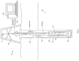
- FIG. 1 illustrates an exemplary embodiment of a downhole measurement, data acquisition, and/or analysis system 10 that includes devices or systems for in-situ measurement of characteristics of an earth formation 12.
- the system 10 includes a magnetic resonance apparatus such as a NMR tool 14.
- An example of the magnetic resonance apparatus is a logging-while-drilling (LWD) magnetic resonance tool.
- the tool 14 is configured to generate magnetic resonance data for use in estimating characteristics of a formation, such as porosity, irreducible water saturation, permeability, hydrocarbon content, and fluid viscosity.
- An exemplary tool 14 includes a static magnetic field source 16 (e.g., the magnets described above) that magnetizes formation materials and a transmitter/receiver assembly 18 (e.g., an antenna, antenna array, or antenna assembly) that transmits RF energy or pulsed energy to provide an oscillating magnetic field in the formation.
- the assembly 18 may also serve the receive function, or distinct receiving antennas may be used for that purpose.
- the tool 14 may include a variety of components and configurations as known in the art of nuclear magnetic resonance or magnetic resonance imaging.
- the tool 14 may be configured as a component of various subterranean systems, such as wireline well logging and LWD systems.
- the tool 14 can be incorporated within a drill string 20 including a drill bit 22 or other suitable carrier and deployed downhole, e.g., from a drilling rig 24 into a borehole 26 during a drilling operation.
- the tool 14 is not limited to the embodiments described herein, and may be deployed in a carrier with alternative conveyance methods.
- a "carrier” as described herein means any device, device component, combination of devices, media and/or member that may be used to convey, house, support or otherwise facilitate the use of another device, device component, combination of devices, media, and/or member.
- Exemplary non-limiting carriers include drill strings of the coiled tube type, of the jointed pipe type, and any combination or portion thereof.
- Other carrier examples include casing pipes, wirelines, wireline sondes, slickline sondes, drop shots, downhole subs, bottom-hole assemblies, and drill strings.
- the tool 14 and/or other downhole components are equipped with transmission equipment to communicate ultimately to a surface processing unit 28.
- Such transmission equipment may take any desired form, and different transmission media and methods may be used, such as wired, fiber optic, and/or wireless transmission methods.
- Additional processing units may be deployed with the carrier.
- a downhole electronics unit 30 includes various electronic components to facilitate receiving signals and collect data, transmitting data and commands, and/or processing data downhole.
- the surface processing unit 28, electronics 30, the tool 14, and/or other components of the system 10 include devices as necessary to provide for storing and/or processing data collected from the tool 14 and other components of the system 10. Exemplary devices include, without limitation, at least one processor, storage, memory, input devices, output devices, and the like.
- magnetic resonance measurements are performed by a nuclear magnetic resonance tool, which generates a static magnetic field (B 0 ) in a volume within the formation using one or more magnets (e.g., the magnetic field source 16).
- An oscillating (e.g., RF) magnetic field (B 1 ) which is at least substantially perpendicular to the static magnetic field, is generated in the volume with an RF antenna.
- a receiving assembly detects the excited NMR signal and captures its relaxation back to thermal equilibrium.
- the signal originates from the net magnetization resulting from the superposition of signal from individual hydrogen protons in the formation fluid.
- These signals are formed using a series of spin echoes (i.e. resulting in an echo train), which are detected by the tool, numerically processed, and ultimately displayed in NMR logs.
- the amplitude of these spin echoes is detected as a function of time, allowing for detection of both the initial amplitude (i.e. for porosity measurement) and the signal decay, which can be used to derive other formation and fluid characteristics after the data inversion procedure.
- the magnetic moments of spin 1 ⁇ 2 nuclei such as those of hydrogen nuclei
- they orient themselves at two angles (i.e. two energy levels) in respect to the static magnetic field and precess about the direction of the applied static magnetic field.
- two energy levels At the relatively low static magnetic fields and high temperatures, typical for an NMR logging tool in an earth formation, the two energy levels have only slightly different populations, resulting in a very small net magnetization.
- T1 and T2 are widely used to characterize the formation and the various fluids contained within the formation.
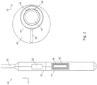
- FIG. 2 illustrates an example of a measurement apparatus configured as a NMR tool 40 for logging a previously-drilled formation.
- the tool 40 in this example is configured as a wireline tool that may be deployed in an open borehole 42.
- the static magnetic field source includes one or more magnet assemblies 44.
- the magnet assemblies 44 described in embodiments herein are permanent magnets, but are not so limited.
- the magnet assemblies include electromagnets, a combination of permanent magnets and electromagnets, or magnets in combination with soft magnetic materials.
- One or more transmit and/or receive antennas are disposed proximal to each permanent magnet assembly 44.
- the tool 40 includes a transmitter assembly that includes an antenna in the form of a transmitting loop coil 46 and a receiving antenna in the form of a receiving loop coil 48.
- the antenna configurations are not limited to those described herein.
- the antennas may be wrapped circumferentially around the magnet assembly or have a different shape or orientation.
- a single coil or group of coils can be configured as both a transmitting and receiving device.
- a sonde 50 or other carrier and an electronics unit 52 connected to the coils 46 and 48, and/or to the magnet assembly 44.
- the electronics unit 52 and/or coils are connected to a surface location via a wireline 54 or other suitable telemetry system.
- the tool 40 is a directional tool placed against the borehole wall and configured to generate strong magnetic fields in a volume of interest within the formation.
- the magnet assembly 44 is oriented so that the static magnetic fields are generally in the transverse (i.e. x-y) plane perpendicular to the length of the borehole and the longitudinal tool axis (the z-axis in this example), and is oriented generally toward the volume of interest.
- the transmitting coil 46 in this example is oriented generally in a plane perpendicular to the x-axis and emits an oscillating magnetic field at least substantially along the x-axis.
- the receiving coil 48 is oriented in the same direction as the transmitting coil 46.
- the coils are "side-looking” in that they are oriented to emit a magnetic field in a specific angular region about the longitudinal borehole (z-directed) axis.
- Components such as an extendable arm 56 may be included and actuated to urge the emitting side of the tool 40 toward the borehole wall, to increase the field strength in the volume of interest, and to reduce or eliminate the influence of borehole fluids on the acquired signal.
- FIG. 3 illustrates various embodiments of magnet assemblies configured to generate a static magnetic field for magnetic resonance measurements.
- Each embodiment may be incorporated in a NMR measurement apparatus, e.g., as the magnet assembly 44, or in any other downhole magnetic resonance device or other device that involves generating a magnetic field in a formation or borehole.
- Each magnet assembly includes an arrangement of permanent magnets 60, electromagnets, or a combination of permanent and/or electromagnets and core sections made from soft magnetic materials.
- the array of magnets 60 are configured to generate a static external magnetic field, B 0 in the formation.
- Each magnet assembly generates a pattern of magnetic field orientations that results in a relatively strong magnetic field on one side of the assembly (a primary side) and a relatively weak or minimal magnetic field on an opposite or adjacent side of the assembly.
- FIG. 3 shows a cross-section in an x-y plane perpendicular to the longitudinal axis (z-axis) of the measurement apparatus. The orientation of the magnetic fields in this plane is shown for each magnet by a collection of arrows. As one progresses along each adjacent magnet 60 in the array (either linearly or along a circumferential path), the angular direction or phase of each magnet segment changes according to a selected pattern.
- the array has a rotating pattern of orientations similar to that of a Halbach array.
- Exemplary patterns of the magnet array are shown in FIG. 3 .
- the magnet geometries, magnetic orientations, and associated B 0 fields are shown for each example pattern.
- the assemblies shown here are cylindrical or semi-cylindrical, other shapes and cross-sections may be used.
- the magnets 60 in the array are placed in contact with one another and affixed to one another by any suitable means.
- the magnets 60 form an array that is wrapped around a center of the assembly along a circumferential path that may be defined by the periphery 62 of the tool.
- a first exemplary magnet assembly 64 includes an array of wedge or pie-shaped magnets 60 forming a full or partial cylinder.
- a second assembly 66 includes an array of magnets 60 arranged in a semi-circular pattern around an empty central portion, which can be used as a conduit for routing cables or fluid, or used to provide space for material that offers structural support.
- alternating magnets 60 in the assembly i.e., every other magnet
- the overall B 0 field pattern exits the front of the tool (i.e. the part of the tool intended to make contact with the borehole) and returns primarily at two distinct locations at a given angular offset around the tool circumference.
- a third assembly 68 also includes an array of wedge-shaped magnets (although pie or similar shapes could also be used) arranged in a semi-circular array around a non-magnetic central segment.
- Assembly 70 for instance, includes an array of magnets forming a solid cylinder, although similar configurations with soft magnetic materials, void spaces, and/or materials providing structural support can also be employed.
- the array of magnets 60 progresses linearly (e.g., along the y-axis), and the orientation of the magnets 60 in the array rotates as the magnets 60 progress from one end of the array to the other.
- the magnet assembly is configured to generate a static magnetic field B 0 that is relatively strong and/or has a larger area on the side of the NMR measurement apparatus that is directed toward the volume of interest.
- the field can be applied to a region of the borehole wall and/or formation, while generating a smaller or minimal magnetic field strength adjacent to the primary field or directed toward the largest unoccupied portion of the borehole.
- FIGs. 4A and 4B shows an embodiment of an NMR apparatus that includes a magnet assembly having an azimuthal static field orientation in front of the tool, i.e. facing the formation volume on interest, and in the x-y plane, with ideally no or minimal z-directed fields.
- the antenna assembly includes a loop coil 104 in FIG. 4B , which is positioned azimuthally so that the loop coil's interior magnetic field is directed toward a volume of interest within the formation.
- the magnetic fields B 0 of the magnet assembly have directions shown by arrows in FIG. 4A that are largely orthogonal to those produced by the RF antennas.
- the loop coil as shown is exemplary only and may include an additional outer loop portion as described below or may have a non-symmetric geometry.
- the RF antenna assembly is configured to receive an oscillating magnetic field B 1 within a given frequency range.
- the tool 100 includes an antenna configured as a loop coil 104 having a rectangular path and generally conforming to the exterior surface of the side of the magnet assembly (largely perpendicular to the x-y plane).
- the magnetic B 1 field of the loop coil is generally oriented in a radial direction along the central coil axis toward the formation. The directions of the B 1 fields are shown with arrow plots in FIG 4B .
- the loop coil 104 is arranged to overlie the magnets such that the B 1 exits from the center of the loop coil, precisely where the static B 0 field is azimuthally (and orthogonally) directed as shown by reference numeral 70 in FIG. 4A .
- the location where the B 0 fields leaves the array 102 is shown by reference numeral 71 and the location where the B 0 fields enter the array 102 is shown by reference numeral 72.
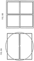
- FIG. 5 an alternative form of a receive coil 500 is shown.
- This type of receive antenna shall be referred to as a butterfly coil and includes first and second coils or loops 502a, 502b connected by a cross-member 504. Overall, the coil segments form a continuous path that produces a distinct B 1 pattern, as shown in FIG 5 . "o" symbols represent magnetic flux directed out of the page and “x” symbols represent magnet flux directed into the page. At the crossover point, magnetic flux is directed horizontally from one loop to the other as indicated by the long arrows.
- the antenna includes a combination of one or more loop coils extended along the length of the magnet assembly 102 (i.e. the longitudinal direction).
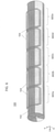
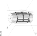
- FIG. 6 shows an exemplary configuration of a NMR apparatus including a permanent magnet array and a RF antenna assembly used to extend sensitivity.
- each loop cool 104 is a receive coil and FIG. 6 is presented to generally illustrate that each loop coil 104 defines a particular region 602a-602e.
- the loop coils are separate from each other but, as discussed below, in at least one embodiment, the loop coils will overlap one another.
- the magnet assembly 102 can be any of the arrays 102 described above or any magnet configuration that generates similar static fields.
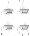
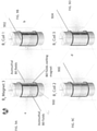
- the magnet assembly 102 is an azimuthal Halbach arrangement (e.g., FIG. 3 ). In that embodiment, and with reference now to FIG. 7A , the magnet assembly 102 produces a specific B 0 field pattern. In FIG. 7B-7D , the spatial distribution of B 1 fields is substantially orthogonal to the corresponding B 0 field pattern shown in FIG. 7A .
- a first loop coil 802 is arranged such that its B 1 is directed primarily from roughly the center of the first loop coil out toward the formation volume of interest 702.
- Two butterfly coils 804 and 806 are arranged such that the cross members 604 of each are located at the locations of magnetic flux exiting from and returning to the magnet assembly. That is, the cross members are arranged such that their corresponding B 1 fields (as illustrated in FIG. 5 ) at the crossover location are substantially perpendicular to the static magnetic fields of the magnet assembly. In other words, the crossover locations are placed at the exit and return flux locations of the magnets (e.g., where the B 0 fields leave and return to the magnet 102) and the loop coil is over the magnet center where the B 0 fields are pointing azimuthally about the magnet 102.
- each longitudinal region of an antenna array 602 can include at least one loop coil 702 and two butterfly coils 704, 706 arranged as described above.
- the above description has focused on the location of the loop and butterfly coils in relation to the B 0 fields. Based on this description, it shall be understood that the locations may be defined based on minimizing mutual inductance (i.e. coupling) among receive coils.
- the butterfly coils may be precisely aligned, either by rotation of the coil or by varying the dimension of the overlapping loop such that mutual inductance is canceled and coupling is minimized.
- butterfly coils can be positioned such that their central axis is equal to the central axis of a surrounding or overlapping loop coil or with a common central axis to another symmetric butterfly coil rotated by 90 degrees i.e. with cross-members orthogonal to each other. These properties allow coils to be completely overlapped or surrounded and still maintain the properties of minimal mutual coupling.
- FIGs. 8A-8B indicates such two-element geometries.
- a third butterfly coil 710 may be arranged such that its cross member is largely perpendicular to those of first and second butterfly coils 704, 706 and such that its B 1 fields are orthogonal to the static B 0 fields, since the static fields are primarily maintained in the transverse x-y plane.
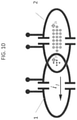
- FIGs. 9A-9D An alternative embodiment is shown in FIGs. 9A-9D , which is complementary to that previously described.
- one butterfly coil (900) is optimally placed in the magnet front, where B0 fields point radially out toward the formation.
- Two loop coils (902, 904) are rotated at a particular angle (in opposite directions) to maximize orthogonality with the static B0 fields, which are in the azimuthal direction at the coil centers.
- a third butterfly coil may be added to this configuration if it is rotated by 90-degrees, as demonstrated in FIG 7E and as illustrated in FIG. 8B
- each region 602 can include from one loop coil and up to 3 butterfly coils in one embodiment as described above, or up to 2 loop coils and 2 butterfly coils in the second embodiment ( FIGs 9A-9D ).
- the primary loop coils overlap one another along the longitudinal direction. It has been discovered that arranging the loop coils 104 such that they overlap may lead to high mutual coupling between them, particularly if soft magnetic core material is used to boost the B 1 field strength of the antenna. If only two sections were required, removing coupling could be accomplished by providing an amount of overlap that minimized such coupling.
- one embodiment includes at least three loop coils distributed along the length of the magnet. With reference now to FIG. 11B , such a configuration could lead to coupling between the first and third 1102, 1106 coils even if the first and second 1102, 1104 coils are arranged to reduce coupling.
- each coil loop includes small outer loops 1110 and 1112 as shown in FIG. 11A . These outer loops are contiguous with the main coil in one embodiment.
- the outer loop of nearest non-adjacent neighbor coils e.g., 1102 and 1106) are overlapped to minimize coupling between them. The amount of overlap between adjacent coils can be determined either empirically or via simulation and is based on loop sizing.
- One method to do this is to increase the physical distance between coils until the mutual inductance is negligible.
- This implies severe restrictions on the coil array geometry, which is ideally optimized based on maximizing the sensitivity of formation measurements.
- Overlap decoupling is a special case for reducing mutual inductance.
- a pair of coils can be optimally placed such that the primary coil's 1 flux (e.g., ⁇ 21 ) into and out of a secondary coil 2 is precisely equal and cancels.
- a benefit of overlap decoupling is that neighboring coils can be closely positioned such that the secondary coil is highly sensitive to the formation predominantly covered by the primary coil, and since measurements are independent, combined signals can result in measurements with higher signal-to-noise ratios over an extended range.
- the flexibility of multi-channel acquisitions also permits potential gains in logging speed and higher vertical resolution.
- Magnetic resonance measurement apparatuses may include an array of receive antenna assemblies distributed about the tool circumference. Each antenna assembly may measure fields so that a larger volume of interest can be interrogated.
- various analyses and/or analytical components may be used, including digital and/or analog subsystems.
- the system may have components such as a processor, storage media, memory, input, output, communications link (wired, wireless, pulsed mud, optical or other), user interfaces, software programs, signal processors and other such components (such as resistors, capacitors, inductors, etc.) to provide for operation and analyses of the apparatus and methods disclosed herein in any of several manners well-appreciated in the art.
- teachings may be, but need not be, implemented in conjunction with a set of computer executable instructions stored on a computer readable medium, including memory (ROMs, RAMs), optical (CD-ROMs), or magnetic (disks, hard drives), or any other type that when executed causes a computer to implement the method of the present invention.
- ROMs, RAMs random access memory
- CD-ROMs compact disc-read only memory
- magnetic (disks, hard drives) any other type that when executed causes a computer to implement the method of the present invention.
- These instructions may provide for equipment operation, control, data collection and analysis and other functions deemed relevant by a system designer, owner, user, or other such personnel, in addition to the functions described in this disclosure.
Landscapes
- Physics & Mathematics (AREA)
- General Physics & Mathematics (AREA)
- Life Sciences & Earth Sciences (AREA)
- Condensed Matter Physics & Semiconductors (AREA)
- High Energy & Nuclear Physics (AREA)
- General Life Sciences & Earth Sciences (AREA)
- Engineering & Computer Science (AREA)
- Environmental & Geological Engineering (AREA)
- Geology (AREA)
- Health & Medical Sciences (AREA)
- General Health & Medical Sciences (AREA)
- Geophysics (AREA)
- Remote Sensing (AREA)
- Vascular Medicine (AREA)
- Geochemistry & Mineralogy (AREA)
- Chemical & Material Sciences (AREA)
- Analytical Chemistry (AREA)
- Biochemistry (AREA)
- Immunology (AREA)
- Pathology (AREA)
- Geophysics And Detection Of Objects (AREA)
- Magnetic Resonance Imaging Apparatus (AREA)
Claims (15)
- Kernspinresonanzvorrichtung zum Schätzen von Eigenschaften einer Erdformation (12), wobei die Vorrichtung Folgendes umfasst:einen Träger, der konfiguriert ist, um in ein Bohrloch (26) in einer Erdformation (12) ausgebracht zu werden, wobei der Träger eine Längsachse aufweist;mindestens eine Magnetbaugruppe (44), die in dem Träger angeordnet ist, um ein statisches Magnetfeld (16) innerhalb eines betreffenden Volumens innerhalb der Erdformation (12) zu erzeugen;mindestens eine Sendebaugruppe (18), die in dem Träger angeordnet ist und konfiguriert ist, um ein oszillierendes Magnetfeld in dem betreffenden Volumen innerhalb der Erdformation (12) zu erzeugen; undmindestens eine Empfängerbaugruppe (18), die in dem Träger angeordnet ist und konfiguriert ist, um ein Kernspinresonanz- (NMR-) Signal zu detektieren, das aus dem betreffenden Volumen stammt;wobei die Empfängerbaugruppe (18) mindestens einen ersten Längsbereich mit einer Spule mit Schleifenwicklung einschließt, wobei die Mittelachse der Spule mit Schleifenwicklung über einem Bereich der Magnetbaugruppe (44) angeordnet ist, wo das statische Magnetfeld (16) vorwiegend entlang einer azimutalen Richtung zum Träger ist, wobei die Vorrichtung dadurch gekennzeichnet ist, dass die Empfängerbaugruppe in dem ersten Längsbereich ferner eine Spule mit seilpuppenförmiger Wicklung einschließt,wobei sich die Spule mit seilpuppenförmiger Wicklung mindestens teilweise mit der Spule mit Schleifenwicklung überlappt, um die gegenseitige Kopplung zu verringern.
- Vorrichtung nach Anspruch 1, wobei die Spule mit seilpuppenförmiger Wicklung winklig/azimutal um die Magnetbaugruppe (44) versetzt ist, so dass ein Querelement davon vorwiegend an einem Punkt des Austritts oder Rücklaufs von statischen Magnetfeldern (16) des Trägers liegt.
- Vorrichtung nach Anspruch 1, wobei die Spule mit seilpuppenförmiger Wicklung eine Mittelachse mit der Spule mit Schleifenwicklung teilt und ein Querelement der Spule mit seilpuppenförmiger Wicklung in einer Ebene liegt, die im Wesentlichen quer zum Träger und senkrecht zur Längsachse verläuft.
- Vorrichtung nach Anspruch 1, wobei der erste Längsbereich eine zweite Spule mit seilpuppenförmiger Wicklung einschließt, die aus zwei Schleifen und einem Querelement besteht, die entfernt von der ersten Spule mit seilpuppenförmiger Wicklung angeordnet ist und deren Querelement vorwiegend an einem Punkt des Austritts oder Rücklaufs von statischem Magnetfeld (16) zur Magnetbaugruppe (44) liegt.
- Vorrichtung nach Anspruch 4, wobei der erste Längsbereich eine dritte Spule mit seilpuppenförmiger Wicklung einschließt, die aus zwei Schleifen und einem Querelement besteht und die eine Mittelachse mit der Spule mit Schleifenwicklung teilt, wobei das Querelement der dritten Spule mit sseilpuppenförmiger Wicklung im Wesentlichen senkrecht zu den Querelementen der ersten und der zweiten Spule mit seilpuppenförmiger Wicklung ist.
- Vorrichtung nach Anspruch 1, wobei die Empfängerbaugruppe (18) einen zweiten Längsbereich einschließt, der eine Spule mit Schleifenwicklung und eine Spule mit seilpuppenförmiger Wicklung, bestehend aus zwei Schleifen und einem Querelement, einschließt, wobei die Spule mit Schleifenwicklung des zweiten Längsbereichs vorwiegend in dem gleichen azimutalen Drehwinkel um den Träger angeordnet ist wie die Spule mit Schleifenwicklung von dem ersten Längsbereich und sich die Spule mit seilpuppenförmiger Wicklung mindestens teilweise mit der Spule mit Schleifenwicklung in dem zweiten Längsbereich überlappt.
- Vorrichtung nach Anspruch 6, wobei die Spule mit Schleifenwicklung des ersten Längsbereichs und die Spule mit Schleifenwicklung des zweiten Längsbereichs jeweils eine zusätzliche äußere Schleife einschließen.
- Vorrichtung nach Anspruch 6, wobei die Empfängerbaugruppe einen dritten Längsbereich einschließt, der eine Spule mit Schleifenwicklung und eine Spule mit seilpuppenförmiger Wicklung, bestehend aus zwei Schleifen und einem Querelement, einschließt.
- Vorrichtung nach Anspruch 8, wobei die Spule mit Schleifenwicklung des ersten Längsbereichs und die Spule mit Schleifenwicklung des dritten Längsbereichs jeweils eine äußere Schleife einschließen.
- Vorrichtung nach Anspruch 9, wobei sich die äußere Schleife der Spule mit Schleifenwicklung des ersten Längsbereichs und die äußere Schleife der Spule mit Schleifenwicklung des dritten Längsbereichs überlappen.
- Vorrichtung nach Anspruch 1, wobei die Magnetbaugruppe (44) ein rotierendes Muster von Magnetfeldern in einer vorwiegend quer verlaufenden Ebene aufweist, die senkrecht zu einer Längsachse der Magnetbaugruppe (44) ist.
- Vorrichtung nach Anspruch 1, wobei die Magnetbaugruppe (44) eine zylindrische oder halbzylindrische Struktur ist und Magnetkomponenten davon eine lineare Matrix von in Längsrichtung länglichen Magneten umfassen.
- Vorrichtung nach Anspruch 1, wobei der erste Längsbereich eine zweite Spule mit Schleifenwicklung enthält, die entfernt von der Spule mit Schleifenwicklung angeordnet ist und deren Mittelachse über einem Bereich der Magnetbaugruppe (44) angeordnet ist, wo ein statisches Magnetfeld (16) vorwiegend entlang der azimutalen Richtung zu dem Träger verläuft.
- Vorrichtung nach Anspruch 13, ferner umfassend eine zweite Spule mit seilpuppenförmiger Wicklung, die aus zwei Schleifen und einem Querelement besteht, die eine Mittelachse mit der Spule mit seilpuppenförmiger Wicklung teilt und deren Querelement im Wesentlichen senkrecht zu einem Querelement der Spule mit seilpuppenförmiger Wicklung ist.
- Vorrichtung nach Anspruch 1, wobei der erste Längsbereich eine zweite Spule mit seilpuppenförmiger Wicklung einschließt, die eine Mittelachse mit der Spule mit seilpuppenförmiger Wicklung teilt, wobei ein Querelement der Spule mit seilpuppenförmiger Wicklung vorwiegend in einer Ebene quer zu einer Längsachse des Trägers enthalten ist, wobei die zweite Spule mit seilpuppenförmiger Wicklung ein Querelement aufweist, das vorwiegend senkrecht zum Querelement der Spule mit seilpuppenförmiger Wicklung ist.
Applications Claiming Priority (2)
| Application Number | Priority Date | Filing Date | Title |
|---|---|---|---|
| US15/166,717 US10145976B2 (en) | 2016-05-27 | 2016-05-27 | Arrays of receive antennas for magnetic resonance measurements |
| PCT/US2017/031700 WO2017205045A1 (en) | 2016-05-27 | 2017-05-09 | Arrays of receive antennas for magnetic resonance measurements |
Publications (3)
| Publication Number | Publication Date |
|---|---|
| EP3465288A1 EP3465288A1 (de) | 2019-04-10 |
| EP3465288A4 EP3465288A4 (de) | 2020-09-09 |
| EP3465288B1 true EP3465288B1 (de) | 2022-02-16 |
Family
ID=60411914
Family Applications (1)
| Application Number | Title | Priority Date | Filing Date |
|---|---|---|---|
| EP17803274.4A Active EP3465288B1 (de) | 2016-05-27 | 2017-05-09 | Anordnungen von empfangsantennen für magnetresonanzmessungen |
Country Status (5)
| Country | Link |
|---|---|
| US (1) | US10145976B2 (de) |
| EP (1) | EP3465288B1 (de) |
| BR (1) | BR112018073332B1 (de) |
| SA (1) | SA518400456B1 (de) |
| WO (1) | WO2017205045A1 (de) |
Families Citing this family (6)
| Publication number | Priority date | Publication date | Assignee | Title |
|---|---|---|---|---|
| US10802176B2 (en) * | 2017-02-14 | 2020-10-13 | Baker Hughes, A Ge Company, Llc | Methods and devices for magnetic resonance measurements using decoupled transmit antennas |
| CN110471121B (zh) | 2019-08-30 | 2021-06-04 | 中国石油大学(北京) | 核磁共振线圈阵列及其去耦合方法、核磁共振探测装置 |
| US11171684B1 (en) * | 2020-06-05 | 2021-11-09 | Baker Hughes Oilfield Operations Llc | Control of tranmsitting and receving antenna properties to reduce electromagnetic coupling |
| US11460600B2 (en) * | 2020-09-09 | 2022-10-04 | Baker Hughes Oilfield Operations Llc | Through-bit reconfigurable NMR logging tool |
| CN113216948B (zh) * | 2021-05-19 | 2023-03-24 | 中国石油大学(北京) | 多线圈结构的随钻核磁共振测井装置及方法 |
| CN120728243B (zh) * | 2025-08-28 | 2025-11-07 | 西北工业大学 | 一种用于极/甚低频电磁探测和通信的磁天线及其应用 |
Family Cites Families (16)
| Publication number | Priority date | Publication date | Assignee | Title |
|---|---|---|---|---|
| NL8603005A (nl) | 1986-11-27 | 1988-06-16 | Philips Nv | Magnetisch resonantie apparaat met flexibele quadratuur spoelenstelsel. |
| US4825162A (en) | 1987-12-07 | 1989-04-25 | General Electric Company | Nuclear magnetic resonance (NMR) imaging with multiple surface coils |
| JPH04180733A (ja) * | 1990-11-16 | 1992-06-26 | Hitachi Ltd | 核磁気共鳴装置用表面コイル |
| US20040066194A1 (en) * | 2001-01-12 | 2004-04-08 | Slade Robert Andrew | Magnetic field generating assembly and method |
| US6720765B2 (en) | 2001-05-30 | 2004-04-13 | Baker Hughes Incorporated | High-resolution high-speed NMR well logging device |
| US6590394B2 (en) * | 2001-09-28 | 2003-07-08 | Varian, Inc. | NMR probe with enhanced power handling ability |
| US6781371B2 (en) | 2002-09-06 | 2004-08-24 | Schlumberger Technology Corporation | High vertical resolution antennas for NMR logging |
| GB0307116D0 (en) * | 2003-03-27 | 2003-04-30 | Oxford Instr Superconductivity | Nuclear magnetic resonance apparatus |
| EP1642156B1 (de) * | 2003-05-02 | 2020-03-04 | Halliburton Energy Services, Inc. | Systeme und verfahren zum nmr-logging |
| US8816684B2 (en) | 2009-11-09 | 2014-08-26 | Vista Clara Inc. | Noise canceling in-situ NMR detection |
| AU2010355326B2 (en) | 2010-06-16 | 2014-02-20 | Halliburton Energy Services, Inc. | Nuclear magnetic resonance logging tool having an array of antennas |
| US8762107B2 (en) * | 2010-09-27 | 2014-06-24 | Baker Hughes Incorporated | Triaxial induction calibration without prior knowledge of the calibration area's ground conductivity |
| US9069098B2 (en) | 2011-09-09 | 2015-06-30 | Schlumberger Technology Corporation | Three or more multiple figure-eight coils for NMR well-logging measurements with azimuthal directional sensitivity |
| CN103412271B (zh) * | 2013-05-08 | 2016-03-30 | 深圳市特深电气有限公司 | 多通道核磁共振线圈 |
| US10197698B2 (en) | 2013-08-30 | 2019-02-05 | Halliburton Energy Services, Inc. | Downhole nuclear magnetic resonance (NMR) tool with transversal-dipole antenna configuration |
| DE102014222938B4 (de) * | 2014-11-11 | 2016-08-18 | Siemens Healthcare Gmbh | MR-Lokalspulensystem, MR-System und Verfahren zum Betreiben desselben |
-
2016
- 2016-05-27 US US15/166,717 patent/US10145976B2/en active Active
-
2017
- 2017-05-09 WO PCT/US2017/031700 patent/WO2017205045A1/en not_active Ceased
- 2017-05-09 BR BR112018073332-6A patent/BR112018073332B1/pt active IP Right Grant
- 2017-05-09 EP EP17803274.4A patent/EP3465288B1/de active Active
-
2018
- 2018-11-18 SA SA518400456A patent/SA518400456B1/ar unknown
Also Published As
| Publication number | Publication date |
|---|---|
| EP3465288A4 (de) | 2020-09-09 |
| BR112018073332A2 (pt) | 2019-02-26 |
| WO2017205045A1 (en) | 2017-11-30 |
| EP3465288A1 (de) | 2019-04-10 |
| US20170343697A1 (en) | 2017-11-30 |
| BR112018073332B1 (pt) | 2023-01-17 |
| US10145976B2 (en) | 2018-12-04 |
| SA518400456B1 (ar) | 2021-11-04 |
Similar Documents
| Publication | Publication Date | Title |
|---|---|---|
| EP3281001B1 (de) | Magnetanordnungen für magnetresonanzmessungen | |
| EP3465288B1 (de) | Anordnungen von empfangsantennen für magnetresonanzmessungen | |
| US8373412B2 (en) | NMR-LWD imaging tool | |
| RU2618241C1 (ru) | Скважинный инструмент ядерного магнитного резонанса (ямр) с избирательностью по азимуту | |
| US8324895B2 (en) | MWD/LWD NMR imaging with long echo trains | |
| AU2012369222B2 (en) | Nuclear magnetic resonance logging tool having multiple pad-mounted atomic magnetometers | |
| NO20200187A1 (en) | Unidirectional Magnetization of Nuclear Magnetic Resonance Tools Having Soft Magnetic Core Material | |
| EP3583294B1 (de) | Verfahren und vorrichtungen für magnetresonanzmessungen mit entkoppelten sendeantennen | |
| EP3585978B1 (de) | Konstruktion von kernspinresonanzvorrichtungen auf der basis von kosten- und struktureinschränkungen | |
| US9223048B2 (en) | System and method to detect a fluid flow without a tipping pulse | |
| US11313991B2 (en) | Directional control of downhole component using NMR measurements | |
| BR112019016861B1 (pt) | Aparelho de ressonância magnética nuclear e método para estimar propriedades de uma formação de terra |
Legal Events
| Date | Code | Title | Description |
|---|---|---|---|
| STAA | Information on the status of an ep patent application or granted ep patent |
Free format text: STATUS: THE INTERNATIONAL PUBLICATION HAS BEEN MADE |
|
| PUAI | Public reference made under article 153(3) epc to a published international application that has entered the european phase |
Free format text: ORIGINAL CODE: 0009012 |
|
| STAA | Information on the status of an ep patent application or granted ep patent |
Free format text: STATUS: REQUEST FOR EXAMINATION WAS MADE |
|
| 17P | Request for examination filed |
Effective date: 20181219 |
|
| AK | Designated contracting states |
Kind code of ref document: A1 Designated state(s): AL AT BE BG CH CY CZ DE DK EE ES FI FR GB GR HR HU IE IS IT LI LT LU LV MC MK MT NL NO PL PT RO RS SE SI SK SM TR |
|
| AX | Request for extension of the european patent |
Extension state: BA ME |
|
| DAV | Request for validation of the european patent (deleted) | ||
| DAX | Request for extension of the european patent (deleted) | ||
| A4 | Supplementary search report drawn up and despatched |
Effective date: 20200810 |
|
| RIC1 | Information provided on ipc code assigned before grant |
Ipc: G01R 33/341 20060101ALI20200804BHEP Ipc: G01V 3/32 20060101AFI20200804BHEP |
|
| GRAP | Despatch of communication of intention to grant a patent |
Free format text: ORIGINAL CODE: EPIDOSNIGR1 |
|
| STAA | Information on the status of an ep patent application or granted ep patent |
Free format text: STATUS: GRANT OF PATENT IS INTENDED |
|
| INTG | Intention to grant announced |
Effective date: 20210927 |
|
| GRAS | Grant fee paid |
Free format text: ORIGINAL CODE: EPIDOSNIGR3 |
|
| GRAA | (expected) grant |
Free format text: ORIGINAL CODE: 0009210 |
|
| STAA | Information on the status of an ep patent application or granted ep patent |
Free format text: STATUS: THE PATENT HAS BEEN GRANTED |
|
| AK | Designated contracting states |
Kind code of ref document: B1 Designated state(s): AL AT BE BG CH CY CZ DE DK EE ES FI FR GB GR HR HU IE IS IT LI LT LU LV MC MK MT NL NO PL PT RO RS SE SI SK SM TR |
|
| RAP3 | Party data changed (applicant data changed or rights of an application transferred) |
Owner name: BAKER HUGHES HOLDINGS LLC |
|
| REG | Reference to a national code |
Ref country code: GB Ref legal event code: FG4D |
|
| REG | Reference to a national code |
Ref country code: CH Ref legal event code: EP |
|
| REG | Reference to a national code |
Ref country code: DE Ref legal event code: R096 Ref document number: 602017053485 Country of ref document: DE |
|
| REG | Reference to a national code |
Ref country code: AT Ref legal event code: REF Ref document number: 1469236 Country of ref document: AT Kind code of ref document: T Effective date: 20220315 |
|
| REG | Reference to a national code |
Ref country code: IE Ref legal event code: FG4D |
|
| REG | Reference to a national code |
Ref country code: NO Ref legal event code: T2 Effective date: 20220216 |
|
| REG | Reference to a national code |
Ref country code: LT Ref legal event code: MG9D |
|
| REG | Reference to a national code |
Ref country code: NL Ref legal event code: MP Effective date: 20220216 |
|
| REG | Reference to a national code |
Ref country code: AT Ref legal event code: MK05 Ref document number: 1469236 Country of ref document: AT Kind code of ref document: T Effective date: 20220216 |
|
| PG25 | Lapsed in a contracting state [announced via postgrant information from national office to epo] |
Ref country code: SE Free format text: LAPSE BECAUSE OF FAILURE TO SUBMIT A TRANSLATION OF THE DESCRIPTION OR TO PAY THE FEE WITHIN THE PRESCRIBED TIME-LIMIT Effective date: 20220216 Ref country code: RS Free format text: LAPSE BECAUSE OF FAILURE TO SUBMIT A TRANSLATION OF THE DESCRIPTION OR TO PAY THE FEE WITHIN THE PRESCRIBED TIME-LIMIT Effective date: 20220216 Ref country code: PT Free format text: LAPSE BECAUSE OF FAILURE TO SUBMIT A TRANSLATION OF THE DESCRIPTION OR TO PAY THE FEE WITHIN THE PRESCRIBED TIME-LIMIT Effective date: 20220616 Ref country code: NL Free format text: LAPSE BECAUSE OF FAILURE TO SUBMIT A TRANSLATION OF THE DESCRIPTION OR TO PAY THE FEE WITHIN THE PRESCRIBED TIME-LIMIT Effective date: 20220216 Ref country code: LT Free format text: LAPSE BECAUSE OF FAILURE TO SUBMIT A TRANSLATION OF THE DESCRIPTION OR TO PAY THE FEE WITHIN THE PRESCRIBED TIME-LIMIT Effective date: 20220216 Ref country code: HR Free format text: LAPSE BECAUSE OF FAILURE TO SUBMIT A TRANSLATION OF THE DESCRIPTION OR TO PAY THE FEE WITHIN THE PRESCRIBED TIME-LIMIT Effective date: 20220216 Ref country code: ES Free format text: LAPSE BECAUSE OF FAILURE TO SUBMIT A TRANSLATION OF THE DESCRIPTION OR TO PAY THE FEE WITHIN THE PRESCRIBED TIME-LIMIT Effective date: 20220216 Ref country code: BG Free format text: LAPSE BECAUSE OF FAILURE TO SUBMIT A TRANSLATION OF THE DESCRIPTION OR TO PAY THE FEE WITHIN THE PRESCRIBED TIME-LIMIT Effective date: 20220516 |
|
| PG25 | Lapsed in a contracting state [announced via postgrant information from national office to epo] |
Ref country code: PL Free format text: LAPSE BECAUSE OF FAILURE TO SUBMIT A TRANSLATION OF THE DESCRIPTION OR TO PAY THE FEE WITHIN THE PRESCRIBED TIME-LIMIT Effective date: 20220216 Ref country code: LV Free format text: LAPSE BECAUSE OF FAILURE TO SUBMIT A TRANSLATION OF THE DESCRIPTION OR TO PAY THE FEE WITHIN THE PRESCRIBED TIME-LIMIT Effective date: 20220216 Ref country code: GR Free format text: LAPSE BECAUSE OF FAILURE TO SUBMIT A TRANSLATION OF THE DESCRIPTION OR TO PAY THE FEE WITHIN THE PRESCRIBED TIME-LIMIT Effective date: 20220517 Ref country code: FI Free format text: LAPSE BECAUSE OF FAILURE TO SUBMIT A TRANSLATION OF THE DESCRIPTION OR TO PAY THE FEE WITHIN THE PRESCRIBED TIME-LIMIT Effective date: 20220216 Ref country code: AT Free format text: LAPSE BECAUSE OF FAILURE TO SUBMIT A TRANSLATION OF THE DESCRIPTION OR TO PAY THE FEE WITHIN THE PRESCRIBED TIME-LIMIT Effective date: 20220216 |
|
| PG25 | Lapsed in a contracting state [announced via postgrant information from national office to epo] |
Ref country code: IS Free format text: LAPSE BECAUSE OF FAILURE TO SUBMIT A TRANSLATION OF THE DESCRIPTION OR TO PAY THE FEE WITHIN THE PRESCRIBED TIME-LIMIT Effective date: 20220617 |
|
| PG25 | Lapsed in a contracting state [announced via postgrant information from national office to epo] |
Ref country code: SM Free format text: LAPSE BECAUSE OF FAILURE TO SUBMIT A TRANSLATION OF THE DESCRIPTION OR TO PAY THE FEE WITHIN THE PRESCRIBED TIME-LIMIT Effective date: 20220216 Ref country code: SK Free format text: LAPSE BECAUSE OF FAILURE TO SUBMIT A TRANSLATION OF THE DESCRIPTION OR TO PAY THE FEE WITHIN THE PRESCRIBED TIME-LIMIT Effective date: 20220216 Ref country code: RO Free format text: LAPSE BECAUSE OF FAILURE TO SUBMIT A TRANSLATION OF THE DESCRIPTION OR TO PAY THE FEE WITHIN THE PRESCRIBED TIME-LIMIT Effective date: 20220216 Ref country code: EE Free format text: LAPSE BECAUSE OF FAILURE TO SUBMIT A TRANSLATION OF THE DESCRIPTION OR TO PAY THE FEE WITHIN THE PRESCRIBED TIME-LIMIT Effective date: 20220216 Ref country code: DK Free format text: LAPSE BECAUSE OF FAILURE TO SUBMIT A TRANSLATION OF THE DESCRIPTION OR TO PAY THE FEE WITHIN THE PRESCRIBED TIME-LIMIT Effective date: 20220216 Ref country code: CZ Free format text: LAPSE BECAUSE OF FAILURE TO SUBMIT A TRANSLATION OF THE DESCRIPTION OR TO PAY THE FEE WITHIN THE PRESCRIBED TIME-LIMIT Effective date: 20220216 |
|
| REG | Reference to a national code |
Ref country code: DE Ref legal event code: R097 Ref document number: 602017053485 Country of ref document: DE |
|
| PG25 | Lapsed in a contracting state [announced via postgrant information from national office to epo] |
Ref country code: AL Free format text: LAPSE BECAUSE OF FAILURE TO SUBMIT A TRANSLATION OF THE DESCRIPTION OR TO PAY THE FEE WITHIN THE PRESCRIBED TIME-LIMIT Effective date: 20220216 |
|
| REG | Reference to a national code |
Ref country code: DE Ref legal event code: R119 Ref document number: 602017053485 Country of ref document: DE |
|
| PLBE | No opposition filed within time limit |
Free format text: ORIGINAL CODE: 0009261 |
|
| STAA | Information on the status of an ep patent application or granted ep patent |
Free format text: STATUS: NO OPPOSITION FILED WITHIN TIME LIMIT |
|
| REG | Reference to a national code |
Ref country code: CH Ref legal event code: PL |
|
| REG | Reference to a national code |
Ref country code: BE Ref legal event code: MM Effective date: 20220531 |
|
| 26N | No opposition filed |
Effective date: 20221117 |
|
| PG25 | Lapsed in a contracting state [announced via postgrant information from national office to epo] |
Ref country code: MC Free format text: LAPSE BECAUSE OF FAILURE TO SUBMIT A TRANSLATION OF THE DESCRIPTION OR TO PAY THE FEE WITHIN THE PRESCRIBED TIME-LIMIT Effective date: 20220216 Ref country code: LU Free format text: LAPSE BECAUSE OF NON-PAYMENT OF DUE FEES Effective date: 20220509 Ref country code: LI Free format text: LAPSE BECAUSE OF NON-PAYMENT OF DUE FEES Effective date: 20220531 Ref country code: CH Free format text: LAPSE BECAUSE OF NON-PAYMENT OF DUE FEES Effective date: 20220531 |
|
| PG25 | Lapsed in a contracting state [announced via postgrant information from national office to epo] |
Ref country code: SI Free format text: LAPSE BECAUSE OF FAILURE TO SUBMIT A TRANSLATION OF THE DESCRIPTION OR TO PAY THE FEE WITHIN THE PRESCRIBED TIME-LIMIT Effective date: 20220216 |
|
| PG25 | Lapsed in a contracting state [announced via postgrant information from national office to epo] |
Ref country code: IE Free format text: LAPSE BECAUSE OF NON-PAYMENT OF DUE FEES Effective date: 20220509 Ref country code: FR Free format text: LAPSE BECAUSE OF NON-PAYMENT OF DUE FEES Effective date: 20220531 |
|
| PG25 | Lapsed in a contracting state [announced via postgrant information from national office to epo] |
Ref country code: DE Free format text: LAPSE BECAUSE OF NON-PAYMENT OF DUE FEES Effective date: 20221201 Ref country code: BE Free format text: LAPSE BECAUSE OF NON-PAYMENT OF DUE FEES Effective date: 20220531 |
|
| P01 | Opt-out of the competence of the unified patent court (upc) registered |
Effective date: 20230526 |
|
| PG25 | Lapsed in a contracting state [announced via postgrant information from national office to epo] |
Ref country code: IT Free format text: LAPSE BECAUSE OF FAILURE TO SUBMIT A TRANSLATION OF THE DESCRIPTION OR TO PAY THE FEE WITHIN THE PRESCRIBED TIME-LIMIT Effective date: 20220216 |
|
| PG25 | Lapsed in a contracting state [announced via postgrant information from national office to epo] |
Ref country code: HU Free format text: LAPSE BECAUSE OF FAILURE TO SUBMIT A TRANSLATION OF THE DESCRIPTION OR TO PAY THE FEE WITHIN THE PRESCRIBED TIME-LIMIT; INVALID AB INITIO Effective date: 20170509 |
|
| PG25 | Lapsed in a contracting state [announced via postgrant information from national office to epo] |
Ref country code: MK Free format text: LAPSE BECAUSE OF FAILURE TO SUBMIT A TRANSLATION OF THE DESCRIPTION OR TO PAY THE FEE WITHIN THE PRESCRIBED TIME-LIMIT Effective date: 20220216 Ref country code: CY Free format text: LAPSE BECAUSE OF FAILURE TO SUBMIT A TRANSLATION OF THE DESCRIPTION OR TO PAY THE FEE WITHIN THE PRESCRIBED TIME-LIMIT Effective date: 20220216 |
|
| PG25 | Lapsed in a contracting state [announced via postgrant information from national office to epo] |
Ref country code: TR Free format text: LAPSE BECAUSE OF FAILURE TO SUBMIT A TRANSLATION OF THE DESCRIPTION OR TO PAY THE FEE WITHIN THE PRESCRIBED TIME-LIMIT Effective date: 20220216 |
|
| PG25 | Lapsed in a contracting state [announced via postgrant information from national office to epo] |
Ref country code: MT Free format text: LAPSE BECAUSE OF FAILURE TO SUBMIT A TRANSLATION OF THE DESCRIPTION OR TO PAY THE FEE WITHIN THE PRESCRIBED TIME-LIMIT Effective date: 20220216 |
|
| PGFP | Annual fee paid to national office [announced via postgrant information from national office to epo] |
Ref country code: GB Payment date: 20250423 Year of fee payment: 9 |
|
| PGFP | Annual fee paid to national office [announced via postgrant information from national office to epo] |
Ref country code: NO Payment date: 20250424 Year of fee payment: 9 |