EP3464869B1 - Valve assembly for an injection valve and injection valve - Google Patents
Valve assembly for an injection valve and injection valve Download PDFInfo
- Publication number
- EP3464869B1 EP3464869B1 EP17725921.5A EP17725921A EP3464869B1 EP 3464869 B1 EP3464869 B1 EP 3464869B1 EP 17725921 A EP17725921 A EP 17725921A EP 3464869 B1 EP3464869 B1 EP 3464869B1
- Authority
- EP
- European Patent Office
- Prior art keywords
- valve
- armature
- slots
- axial
- needle
- Prior art date
- Legal status (The legal status is an assumption and is not a legal conclusion. Google has not performed a legal analysis and makes no representation as to the accuracy of the status listed.)
- Active
Links
Images

Classifications
-
- F—MECHANICAL ENGINEERING; LIGHTING; HEATING; WEAPONS; BLASTING
- F02—COMBUSTION ENGINES; HOT-GAS OR COMBUSTION-PRODUCT ENGINE PLANTS
- F02M—SUPPLYING COMBUSTION ENGINES IN GENERAL WITH COMBUSTIBLE MIXTURES OR CONSTITUENTS THEREOF
- F02M51/00—Fuel-injection apparatus characterised by being operated electrically
- F02M51/06—Injectors peculiar thereto with means directly operating the valve needle
- F02M51/061—Injectors peculiar thereto with means directly operating the valve needle using electromagnetic operating means
- F02M51/0625—Injectors peculiar thereto with means directly operating the valve needle using electromagnetic operating means characterised by arrangement of mobile armatures
- F02M51/0664—Injectors peculiar thereto with means directly operating the valve needle using electromagnetic operating means characterised by arrangement of mobile armatures having a cylindrically or partly cylindrically shaped armature, e.g. entering the winding; having a plate-shaped or undulated armature entering the winding
- F02M51/0671—Injectors peculiar thereto with means directly operating the valve needle using electromagnetic operating means characterised by arrangement of mobile armatures having a cylindrically or partly cylindrically shaped armature, e.g. entering the winding; having a plate-shaped or undulated armature entering the winding the armature having an elongated valve body attached thereto
-
- B—PERFORMING OPERATIONS; TRANSPORTING
- B05—SPRAYING OR ATOMISING IN GENERAL; APPLYING FLUENT MATERIALS TO SURFACES, IN GENERAL
- B05B—SPRAYING APPARATUS; ATOMISING APPARATUS; NOZZLES
- B05B1/00—Nozzles, spray heads or other outlets, with or without auxiliary devices such as valves, heating means
- B05B1/30—Nozzles, spray heads or other outlets, with or without auxiliary devices such as valves, heating means designed to control volume of flow, e.g. with adjustable passages
- B05B1/3033—Nozzles, spray heads or other outlets, with or without auxiliary devices such as valves, heating means designed to control volume of flow, e.g. with adjustable passages the control being effected by relative coaxial longitudinal movement of the controlling element and the spray head
- B05B1/304—Nozzles, spray heads or other outlets, with or without auxiliary devices such as valves, heating means designed to control volume of flow, e.g. with adjustable passages the control being effected by relative coaxial longitudinal movement of the controlling element and the spray head the controlling element being a lift valve
- B05B1/3046—Nozzles, spray heads or other outlets, with or without auxiliary devices such as valves, heating means designed to control volume of flow, e.g. with adjustable passages the control being effected by relative coaxial longitudinal movement of the controlling element and the spray head the controlling element being a lift valve the valve element, e.g. a needle, co-operating with a valve seat located downstream of the valve element and its actuating means, generally in the proximity of the outlet orifice
- B05B1/3053—Nozzles, spray heads or other outlets, with or without auxiliary devices such as valves, heating means designed to control volume of flow, e.g. with adjustable passages the control being effected by relative coaxial longitudinal movement of the controlling element and the spray head the controlling element being a lift valve the valve element, e.g. a needle, co-operating with a valve seat located downstream of the valve element and its actuating means, generally in the proximity of the outlet orifice the actuating means being a solenoid
-
- F—MECHANICAL ENGINEERING; LIGHTING; HEATING; WEAPONS; BLASTING
- F02—COMBUSTION ENGINES; HOT-GAS OR COMBUSTION-PRODUCT ENGINE PLANTS
- F02M—SUPPLYING COMBUSTION ENGINES IN GENERAL WITH COMBUSTIBLE MIXTURES OR CONSTITUENTS THEREOF
- F02M51/00—Fuel-injection apparatus characterised by being operated electrically
- F02M51/06—Injectors peculiar thereto with means directly operating the valve needle
- F02M51/061—Injectors peculiar thereto with means directly operating the valve needle using electromagnetic operating means
- F02M51/0625—Injectors peculiar thereto with means directly operating the valve needle using electromagnetic operating means characterised by arrangement of mobile armatures
- F02M51/0664—Injectors peculiar thereto with means directly operating the valve needle using electromagnetic operating means characterised by arrangement of mobile armatures having a cylindrically or partly cylindrically shaped armature, e.g. entering the winding; having a plate-shaped or undulated armature entering the winding
- F02M51/0685—Injectors peculiar thereto with means directly operating the valve needle using electromagnetic operating means characterised by arrangement of mobile armatures having a cylindrically or partly cylindrically shaped armature, e.g. entering the winding; having a plate-shaped or undulated armature entering the winding the armature and the valve being allowed to move relatively to each other or not being attached to each other
-
- F—MECHANICAL ENGINEERING; LIGHTING; HEATING; WEAPONS; BLASTING
- F02—COMBUSTION ENGINES; HOT-GAS OR COMBUSTION-PRODUCT ENGINE PLANTS
- F02M—SUPPLYING COMBUSTION ENGINES IN GENERAL WITH COMBUSTIBLE MIXTURES OR CONSTITUENTS THEREOF
- F02M61/00—Fuel-injectors not provided for in groups F02M39/00 - F02M57/00 or F02M67/00
- F02M61/04—Fuel-injectors not provided for in groups F02M39/00 - F02M57/00 or F02M67/00 having valves, e.g. having a plurality of valves in series
- F02M61/10—Other injectors with elongated valve bodies, i.e. of needle-valve type
-
- F—MECHANICAL ENGINEERING; LIGHTING; HEATING; WEAPONS; BLASTING
- F02—COMBUSTION ENGINES; HOT-GAS OR COMBUSTION-PRODUCT ENGINE PLANTS
- F02M—SUPPLYING COMBUSTION ENGINES IN GENERAL WITH COMBUSTIBLE MIXTURES OR CONSTITUENTS THEREOF
- F02M2200/00—Details of fuel-injection apparatus, not otherwise provided for
- F02M2200/28—Details of throttles in fuel-injection apparatus
-
- F—MECHANICAL ENGINEERING; LIGHTING; HEATING; WEAPONS; BLASTING
- F02—COMBUSTION ENGINES; HOT-GAS OR COMBUSTION-PRODUCT ENGINE PLANTS
- F02M—SUPPLYING COMBUSTION ENGINES IN GENERAL WITH COMBUSTIBLE MIXTURES OR CONSTITUENTS THEREOF
- F02M2200/00—Details of fuel-injection apparatus, not otherwise provided for
- F02M2200/30—Fuel-injection apparatus having mechanical parts, the movement of which is damped
- F02M2200/304—Fuel-injection apparatus having mechanical parts, the movement of which is damped using hydraulic means
Definitions
- the present disclosure relates to a valve assembly for an injection valve and to an injection valve, e.g. a fuel injection valve of a vehicle. It particularly relates to solenoid injection valves.
- US 2011/198419 A1 discloses a fuel injection valve, which includes a needle valve having an engagement part and a movable core having an engagement part to be engaged with the engagement part of the needle valve.
- One of the engagement part of the needle valve and the engagement part of the movable core is defined by two inner faces of a recess opposing to each other in an axis direction, and the other engagement part is defined by two outer faces of a projection opposing to the inner faces, respectively.
- the projection is movable between the inner faces in the axis direction in a state that the projection is located in the recess.
- EP 2597296 B1 relates to a valve assembly for an injection valve, with a valve body including a central longitudinal axis, the valve body comprising a cavity with a fluid inlet portion and a fluid outlet portion, with a valve needle axially movable in the cavity, the valve needle preventing a fluid flow through the fluid outlet portion in a closing position and releasing the fluid flow through the fluid outlet portion in further positions, with an upper retainer being arranged in the cavity and being fixedly coupled to the valve needle, with an electro-magnetic actuator unit being designed to actuate the valve needle, the actuator unit comprising an armature arrangement which is arranged in the cavity and is axially moveable relative to the valve needle, the armature arrangement being designed to be coupled to the upper retainer when the valve needle is actuated to leave the closing position, the armature arrangement being designed and arranged to mechanically decouple from the upper retainer due to its inertia when the valve needle reaches the closing position.
- the fuel injection valve disclosed by JP 2015-124612 A intends to suppress the overshoot of a valve body generated when opening a valve, without deteriorating responsivity, in a fuel injection valve having a valve portion separately composed of a valve body and an anchor. It has a valve portion in which a valve body formed in an axial direction of a body and opening/closing a nozzle port, and an anchor disposed on an outer periphery of the valve body, sucked to a fixed core by energization to an electromagnetic coil, and separated from the fixed core by the stopping of the energization to the electromagnetic coil can be relatively moved in an axial direction of the body.
- a fuel reservoir is formed between the anchor and the valve body, and the anchor is formed with a limiting channel for communicating the fuel reservoir and a fuel passage. The limiting channel intercepts communication with the fuel passage when the anchor is sucked to the fixed core.
- a valve assembly for an injection valve comprising a valve body comprising a cavity with a fluid inlet portion and a fluid outlet portion and a valve needle axially moveable in the cavity.
- the valve needle prevents a fluid flow through the fluid outlet portion in a closing position and releases the fluid flow through the fluid outlet portion in further positions.
- the valve assembly comprises an upper retaining element fixedly connected to the valve needle and extending in radial direction - i.e. in particular extending radially outward from the valve needle.
- the retaining element is preferably arranged in an axial region of the valve needle facing away from - i.e. in particular remote from - the fluid outlet portion.
- the valve assembly further comprises an armature.
- the valve assembly comprises an electro-magnetic actuator unit being operable to actuate the valve needle and comprising the armature.
- the armature is axially movable in the cavity relative to the valve body. It comprises a central axial opening through which the valve needle extends.
- the armature is able to slide on the valve needle, the upper retaining element limiting the axial displaceability of the armature relative to the valve needle, in particular in a first axial direction.
- the axial displaceability of the armature relative to the valve needle in a second axial direction, opposite to the first axial direction is limited by a stopper which may be fixedly connected either to the valve needle or the valve body on the side of the armature remote from the upper retaining element.
- the valve needle projects from the central axial opening, and in particular from the armature, in both axial directions.
- the armature further comprises a number of axial slots arranged adjacent to and connected with the central axial opening, the slots extending through the armature in axial direction.
- each slot may extend over the entire length of the central axial opening, the length being the extension in axial direction.
- the slots extend completely through the armature in axial direction. That the slots are "connected with the central opening” means in particular that the slots are connected to and open to the central axial opening on their entire length, the length being the extension in axial direction.
- that the slots are "connected with the central opening” means in particular that each slot has an interface fluidly connecting the slot to the central opening, the interface extending over the entire length of the slot.
- the slots are arranged adjacent to the central opening such that they are fluidly connected with the central opening.
- the slots extend radially outward from the central axial opening.
- the slots form a flow path along the inner diameter of the armature.
- the armature is in sliding mechanical contact with the valve needle, in particular in the region of the central axial opening.
- a surface portion of the armature which defines the central axial opening is operable to slide along an outer circumferential surface of the valve needle for axially guiding the armature.
- the upper retaining element has a portion extending axially into the central axial opening of the armature so that it is arranged radially between the valve needle and the armature.
- the armature is preferably in sliding mechanical contact with the upper retaining element, in particular in the region of the central axial opening.
- the surface portion of the armature which defines the central axial opening is operable to slide along an outer circumferential surface of the above-mentioned portion of the upper retaining element for axially guiding the armature.
- for axially guiding the armature may in particular imply that the needle is axially guided relative to the valve body, for example by means of a sliding contact of the upper retaining element with the valve body or another part of the valve assembly which is positionally fix relative to the valve body (such as a pole piece of the actuator unit).
- the armature actually guides the valve needle and the armature itself is axially guided relative to the valve body by sliding mechanical contact of an external surface of the armature with the valve body.
- the upper retaining element projects beyond the central axial opening in radially outward direction.
- the upper retaining element is - or has a portion which is - arranged subsequently to the central axial opening in the first axial direction and projects beyond the central axial opening in radially outward direction.
- the armature is operable to engage with the upper retaining element in a form-fit connection for axially displacing the valve needle.
- the slots project beyond the upper retaining element in radial outward direction. In this way, particularly small hydraulic sticking between the upper retaining element and the armature is achievable.
- the axial slots are semicircular in cross-section.
- the term "semicircular” shall also denote a rounded cross-section that is not exactly semicircular.
- the axial slots may also have a different cross-section, e.g. be rectangular in cross-section.
- the cross-sectional form of the slots has only a minor influence on the fluid flow as long as the slots do not get too narrow, thereby providing a considerable flow resistance. Therefore, the cross-sectional form may be chosen so as to simplify manufacture of the armature.
- the axial slots may be straight and extend parallel to the needle. According to another embodiment, they may extend in axial direction in a curved manner. The curve may or may not be axially symmetric.
- the axial slots may extend in axial direction along a helical curve.
- the slots twist around the central opening in a helically curved fashion.
- the slots extend over at least one quarter of the circumference of the central axial opening. This means in particular that all the slots together extend over at least one quarter of the circumference of the central axial opening. It may e.g. be advantageous, if the slots extend over approximately 50% of the circumference.
- the armature has a central axial passage constituted by the central axial opening and the slots. The central axial passage is in particular simply connected.
- the central axial opening and its interfaces with the slots preferably define an imaginary cylindrical surface.
- the interfaces of the slots with the central axial opening preferably make up at least one quarter of the imaginary cylindrical surface, for example about 50 % of the imaginary cylindrical surface.
- the dimension, shape and number of slots may be optimized based on the injector configuration.
- the hydraulic diameter of the flow path formed by the slots should be large enough to prevent hydraulic sticking between armature and upper retaining element.
- the valve assembly further comprises at least one outer axial slot - preferably one ore more through-holes - which is/are spaced apart from the central axial opening and from the slots in radial direction and extends through the armature in axial direction, for example parallel or oblique to the longitudinal axis.
- a particularly large hydraulic diameter is achievable with the slots and the outer axial slots together.
- the valve needle is a solid - i.e. not hollow - body in one embodiment. At least in this embodiment, the valve needle does not comprise a recess which extends axially through a portion of the valve needle for enabling fluid flow through the armature. This contributes to making the manufacture of the valve assembly cost-efficient and particularly precise.
- the valve needle may be particularly robust in this way.
- an injection valve with the described valve assembly is provided.
- the injection valve may in particular be a fuel injection valve of a vehicle.
- valve assembly for an injection valve the fluid injection valve and the method for manufacturing a fluid injection valve will become apparent from the exemplary embodiments which are described below in association with schematic figures.
- Figure 1 shows an injection valve 1 that is in particular suitable for dosing fuel to an internal combustion engine.
- the injection valve 1 comprises a valve assembly 3.
- the valve assembly 3 comprises a valve body 4 with a central longitudinal axis L.
- a housing 6 is partially arranged around the valve body 4.
- the valve body 4 comprises a cavity 9.
- the cavity 9 has a fluid outlet portion 7.
- the fluid outlet portion 7 communicates with a fluid inlet portion 5 which is provided in the valve body 4.
- the fluid inlet portion 5 and the fluid outlet portion 7 are in particular positioned at opposite axial ends of the valve body 4.
- the cavity 9 takes in a valve needle 11.
- the valve needle 11 comprises a needle shaft 15 and a sealing ball 13 welded to the tip of the needle shaft 15.
- the valve needle 11 In a closing position of the valve needle 11, it sealingly rests on a seat plate 17 having at least one injection nozzle.
- a preloaded calibration spring 18 exerts a force on the needle 11, biasing the valve needle 11 towards the closing position.
- the fluid outlet portion 7 is arranged near the seat plate 17. In the closing position of the valve needle 11, a fluid flow through the at least one injection nozzle is prevented.
- the injection nozzle may be, for example, an injection hole. However, it may also be of some other type suitable for dosing fluid.
- the injection valve 1 is provided with an electro-magnetic actuator unit 19.
- the electro-magnetic actuator unit 19 comprises a coil 21, which is preferably arranged inside the housing 6, outside of the valve body 4. Furthermore, the electro-magnetic actuator unit 19 comprises an armature 23, being in particular also part of the valve assembly 3.
- the housing 6, parts of the valve body 4 and the armature 23 form an electromagnetic circuit.
- the actuator unit 19 further comprises a pole piece 25 fixed to or represented by the valve body 4.
- the armature 23 is axially movable in the cavity 9.
- the armature 23 is axially movable relative to the valve needle 11, i.e. it may slide on the needle 11, and also to the valve body 4.
- the valve assembly 3 comprises an upper retaining element 24.
- the upper retaining element 24 is formed as a collar around the axial end 22 of the valve needle 11.
- the upper retaining element 24 is fixedly coupled to the axial end 22 of the valve needle 11.
- the needle 11 is guided by a central axial opening 26 in the armature 23. More specifically, a portion of the upper retaining element 24 extends axially into the central axial opening 26 so that it is arranged radially between the needle 11 and the armature 26. An outer surface of said portion is in sliding mechanical contact with an inner circumferential surface of the armature 23 which defines the central axial opening.
- a spring element 46 is arranged axially between the upper retaining element 24 and the armature 23. For example, it is arranged in a recess 28 of the armature 23 between the upper retaining element 24 and a protrusion 29 of the armature 23.
- the spring element 46 enables a transmission of forces between the protrusion 29 of the armature 23 and the upper retaining element 24.
- the spring element 46 is preloaded so that in a closing position of the valve 1, the armature 23 is spaced apart from the upper retaining element 24 and in particular in contact with a lower retaining element 48.
- the lower retaining element 48 also referred to as "hydraulic damping disc", is axially positioned on the side of the armature 23 remote from the upper retaining element 24. In the present embodiment, it is arranged in the cavity 9 axially between a step 44 of an inner surface of the valve body 4 and the armature 23.
- the lower retaining element 48 may be formed as a collar around the valve needle 11 and is fixedly attached to the valve needle 11. It is also useful for other embodiments of the invention.
- the lower retaining element 48 can decrease the velocity of the armature 23 and ultimately stop the armature 23 when the valve needle 11 stops in the closed position and the armature 23 decouples from the upper retaining element 24 due to its inertia and moves further towards the fluid outlet portion 7.
- the armature 23 has a number of axial slots 27 arranged adjacent to and connected with the central axial opening 26, the slots 27 extend through the armature 23 in axial direction.
- the axial slots 27 are straight and extend all the way parallel to the central axial opening 26.
- the armature 23 may comprise a larger number of slots 27.
- outer axial slots 30 are arranged in the armature 23, too.
- the outer axial slots 30 are not directly fluidly connected to the central opening. In other words, they are spaced apart from the central axial opening 26 and from the slots 27 in radial direction. They provide a flow path for fuel and can help prevent eddy currents.
- the outer axial slots 30 are represented by through-holes extending through the armature 23 in axial direction.
- the upper retaining element 24 extends beyond the central axial opening 26 in radially outward direction so that it overlaps, in top view along the longitudinal axis, with a surface of the armature 23 facing towards the pole piece 25.
- the valve needle 11 and the retaining element 24 together completely overlap the central axial opening 26.
- the armature 23 When the coil 21 is energized, the armature 23 experiences a magnetic force and slides upwards towards the pole piece 25, moving in axial direction away from the fluid outlet portion 7. After having travelled to close the gap, the armature 23 takes the valve needle 11 with it towards the pole piece 25 via a form-fit engagement of its surface facing towards the pole piece 25 with the upper retaining element 24. Consequently, the valve needle 11 moves in axial direction out of the closing position of the valve 1.
- a gap between the valve body 4 and the valve needle 11 at the axial end of the injection valve 1 facing away from of the actuator unit 19 forms a fluid path and fluid can pass through the injection nozzle.
- the calibration spring 18 can force the valve needle 11 to move in axial direction into its closing position.
- the armature 23 detaches from the upper retaining element 24. This detachment is facilitated by fuel squeezed through the slots 27.
- the kinetic energy of the armature 23 needs to be dissipated, to avoid needle bounce which may lead to an undesired reopening of the valve 1. A part of the kinetic energy may be dissipated by squeezing fuel through the slots 27 and 30.
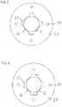
- Figure 2 shows a cross-sectional detailed view of a first embodiment of an armature 23 of the injection valve 1 according to figure 1 .
- the armature 23 has four slots 27 arranged adjacent to the central axial opening 26.
- the slots 27 and the central axial opening 26 completely overlap each other in axial direction.
- the axial ends of the slots 27 and the central axial opening 26 are arranged at the same axial positions.
- the slots 27 are semicircular in cross-section, the opening of the semicircular shapes of the slots 27 representing the interfaces with the central axial opening 26.
- the cross-section of the slots 27 is in particular translation invariant with respect to translation along the longitudinal axis L.
- the slots 27 extend over approximately half the circumference of the central axial opening 26.
- Figure 3 shows a cross-sectional detailed view of a second embodiment of an armature 23 of the injection valve 1 according to figure 1 .
- This embodiment only differs from the first in that the slots 27 are rectangular in cross-section.
- the upper retaining element 24 completely overlaps the slots 27 in top view along the longitudinal axis L. According to the invention, the slots 27 project beyond the upper retaining element 24 in radially outward direction.
Landscapes
- Engineering & Computer Science (AREA)
- Chemical & Material Sciences (AREA)
- Combustion & Propulsion (AREA)
- Mechanical Engineering (AREA)
- General Engineering & Computer Science (AREA)
- Physics & Mathematics (AREA)
- Electromagnetism (AREA)
- Magnetically Actuated Valves (AREA)
- Fuel-Injection Apparatus (AREA)
Description
- The present disclosure relates to a valve assembly for an injection valve and to an injection valve, e.g. a fuel injection valve of a vehicle. It particularly relates to solenoid injection valves.
- Such injection valves must be able to dose fluids even in the case of high fuel pressure. One design to ensure this is the "free-lift" design, an embodiment of which is disclosed in document
EP 2 333 297 B1 . According to this design, the armature of the electro-magnetic actuator unit travels about a "pre-stroke gap" before it engages the needle to open the injector. Thus, kinetic energy is accumulated before the actual opening. - However, during the closing transient of such an injection valve, kinetic energy of the armature must be dissipated in order to avoid bounce and post injection events.
-
US 2011/198419 A1 discloses a fuel injection valve, which includes a needle valve having an engagement part and a movable core having an engagement part to be engaged with the engagement part of the needle valve. One of the engagement part of the needle valve and the engagement part of the movable core is defined by two inner faces of a recess opposing to each other in an axis direction, and the other engagement part is defined by two outer faces of a projection opposing to the inner faces, respectively. The projection is movable between the inner faces in the axis direction in a state that the projection is located in the recess. -
EP 2597296 B1 relates to a valve assembly for an injection valve, with a valve body including a central longitudinal axis, the valve body comprising a cavity with a fluid inlet portion and a fluid outlet portion, with a valve needle axially movable in the cavity, the valve needle preventing a fluid flow through the fluid outlet portion in a closing position and releasing the fluid flow through the fluid outlet portion in further positions, with an upper retainer being arranged in the cavity and being fixedly coupled to the valve needle, with an electro-magnetic actuator unit being designed to actuate the valve needle, the actuator unit comprising an armature arrangement which is arranged in the cavity and is axially moveable relative to the valve needle, the armature arrangement being designed to be coupled to the upper retainer when the valve needle is actuated to leave the closing position, the armature arrangement being designed and arranged to mechanically decouple from the upper retainer due to its inertia when the valve needle reaches the closing position. - The fuel injection valve disclosed by
JP 2015-124612 A - It is an object of the present disclosure to provide a valve assembly for an injection valve that overcomes the above mentioned difficulties and/or which provides a stable performance even under conditions of high fluid pressure.
- This object is achieved by means of a valve assembly according to the independent claim.
- Advantageous embodiments and developments are specified in the dependent claims, the following description and the drawings.
- According to an aspect of the disclosure a valve assembly for an injection valve is provided, comprising a valve body comprising a cavity with a fluid inlet portion and a fluid outlet portion and a valve needle axially moveable in the cavity. The valve needle prevents a fluid flow through the fluid outlet portion in a closing position and releases the fluid flow through the fluid outlet portion in further positions.
- The valve assembly comprises an upper retaining element fixedly connected to the valve needle and extending in radial direction - i.e. in particular extending radially outward from the valve needle. The retaining element is preferably arranged in an axial region of the valve needle facing away from - i.e. in particular remote from - the fluid outlet portion.
- The valve assembly further comprises an armature. In one embodiment, the valve assembly comprises an electro-magnetic actuator unit being operable to actuate the valve needle and comprising the armature.
- The armature is axially movable in the cavity relative to the valve body. It comprises a central axial opening through which the valve needle extends. The armature is able to slide on the valve needle, the upper retaining element limiting the axial displaceability of the armature relative to the valve needle, in particular in a first axial direction. In one embodiment, the axial displaceability of the armature relative to the valve needle in a second axial direction, opposite to the first axial direction is limited by a stopper which may be fixedly connected either to the valve needle or the valve body on the side of the armature remote from the upper retaining element. In one embodiment, the valve needle projects from the central axial opening, and in particular from the armature, in both axial directions.
- The armature further comprises a number of axial slots arranged adjacent to and connected with the central axial opening, the slots extending through the armature in axial direction. Expediently, each slot may extend over the entire length of the central axial opening, the length being the extension in axial direction. In particular, the slots extend completely through the armature in axial direction. That the slots are "connected with the central opening" means in particular that the slots are connected to and open to the central axial opening on their entire length, the length being the extension in axial direction. To put it differently, that the slots are "connected with the central opening" means in particular that each slot has an interface fluidly connecting the slot to the central opening, the interface extending over the entire length of the slot.
- It is an advantage of this valve assembly, that fluid may be squeezed through the slots during closing of the valve, thereby dissipating energy of the armature and dampening the armature. Fluid flow through the slots reduces hydraulic sticking between the armature and the upper retaining element, but at the same time keeps the impact face between the armature and the upper retaining element which helps prevent the reduction of parts surface durability.
- The slots are arranged adjacent to the central opening such that they are fluidly connected with the central opening. In particular, the slots extend radially outward from the central axial opening. Thus, the slots form a flow path along the inner diameter of the armature.
- There may only be provided one single slot or a larger number of slots. In order to keep a secure guidance of the needle, a number of about three to eight evenly spaced slots may be found advantageous in most designs.
- In one embodiment, the armature is in sliding mechanical contact with the valve needle, in particular in the region of the central axial opening. In other words, a surface portion of the armature which defines the central axial opening is operable to slide along an outer circumferential surface of the valve needle for axially guiding the armature.
- In another embodiment, the upper retaining element has a portion extending axially into the central axial opening of the armature so that it is arranged radially between the valve needle and the armature. In this case, the armature is preferably in sliding mechanical contact with the upper retaining element, in particular in the region of the central axial opening. In other words, the surface portion of the armature which defines the central axial opening is operable to slide along an outer circumferential surface of the above-mentioned portion of the upper retaining element for axially guiding the armature.
- In this context "for axially guiding the armature" may in particular imply that the needle is axially guided relative to the valve body, for example by means of a sliding contact of the upper retaining element with the valve body or another part of the valve assembly which is positionally fix relative to the valve body (such as a pole piece of the actuator unit). However also such embodiments shall included where the armature actually guides the valve needle and the armature itself is axially guided relative to the valve body by sliding mechanical contact of an external surface of the armature with the valve body.
- Particularly small tolerances of the armature/needle guidance may be achieved by these embodiments without increasing the bounce. This helps reduce dimensions of the injector. The quality of the needle guidance is not reduced by the slots.
- According to the invention, the upper retaining element projects beyond the central axial opening in radially outward direction. In one development, the upper retaining element is - or has a portion which is - arranged subsequently to the central axial opening in the first axial direction and projects beyond the central axial opening in radially outward direction. In this way, the armature is operable to engage with the upper retaining element in a form-fit connection for axially displacing the valve needle.
- According to the invention, the slots project beyond the upper retaining element in radial outward direction. In this way, particularly small hydraulic sticking between the upper retaining element and the armature is achievable.
- According to one embodiment, the axial slots are semicircular in cross-section. The term "semicircular" shall also denote a rounded cross-section that is not exactly semicircular. In other embodiments, the axial slots may also have a different cross-section, e.g. be rectangular in cross-section. The cross-sectional form of the slots has only a minor influence on the fluid flow as long as the slots do not get too narrow, thereby providing a considerable flow resistance. Therefore, the cross-sectional form may be chosen so as to simplify manufacture of the armature.
- The axial slots may be straight and extend parallel to the needle. According to another embodiment, they may extend in axial direction in a curved manner. The curve may or may not be axially symmetric.
- For example, the axial slots may extend in axial direction along a helical curve. According to this embodiment, the slots twist around the central opening in a helically curved fashion.
- According to one embodiment, the slots extend over at least one quarter of the circumference of the central axial opening. This means in particular that all the slots together extend over at least one quarter of the circumference of the central axial opening. It may e.g. be advantageous, if the slots extend over approximately 50% of the circumference. To put it differently, the armature has a central axial passage constituted by the central axial opening and the slots. The central axial passage is in particular simply connected. The central axial opening and its interfaces with the slots preferably define an imaginary cylindrical surface. The interfaces of the slots with the central axial opening preferably make up at least one quarter of the imaginary cylindrical surface, for example about 50 % of the imaginary cylindrical surface.
- The dimension, shape and number of slots may be optimized based on the injector configuration. The hydraulic diameter of the flow path formed by the slots should be large enough to prevent hydraulic sticking between armature and upper retaining element.
- In one embodiment, the valve assembly further comprises at least one outer axial slot - preferably one ore more through-holes - which is/are spaced apart from the central axial opening and from the slots in radial direction and extends through the armature in axial direction, for example parallel or oblique to the longitudinal axis. A particularly large hydraulic diameter is achievable with the slots and the outer axial slots together.
- The valve needle is a solid - i.e. not hollow - body in one embodiment. At least in this embodiment, the valve needle does not comprise a recess which extends axially through a portion of the valve needle for enabling fluid flow through the armature. This contributes to making the manufacture of the valve assembly cost-efficient and particularly precise. The valve needle may be particularly robust in this way.
- According to one aspect of the invention, an injection valve with the described valve assembly is provided. The injection valve may in particular be a fuel injection valve of a vehicle.
- Further advantages, advantageous embodiments and developments of the valve assembly for an injection valve, the fluid injection valve and the method for manufacturing a fluid injection valve will become apparent from the exemplary embodiments which are described below in association with schematic figures.
- Figure 1
- shows a sectional view of an injection valve with a valve assembly according to one embodiment of the invention;
- Figure 2
- shows a cross-sectional detailed view of a first embodiment of an armature of the injection valve 1 according to
figure 1 and - Figure 3
- shows a cross-sectional detailed view of a second embodiment of an armature of the injection valve 1 according to
figure 1 . -
Figure 1 shows an injection valve 1 that is in particular suitable for dosing fuel to an internal combustion engine. The injection valve 1 comprises a valve assembly 3. The valve assembly 3 comprises avalve body 4 with a central longitudinal axis L. Ahousing 6 is partially arranged around thevalve body 4. - The
valve body 4 comprises a cavity 9. The cavity 9 has afluid outlet portion 7. Thefluid outlet portion 7 communicates with afluid inlet portion 5 which is provided in thevalve body 4. Thefluid inlet portion 5 and thefluid outlet portion 7 are in particular positioned at opposite axial ends of thevalve body 4. The cavity 9 takes in a valve needle 11. The valve needle 11 comprises aneedle shaft 15 and a sealingball 13 welded to the tip of theneedle shaft 15. - In a closing position of the valve needle 11, it sealingly rests on a seat plate 17 having at least one injection nozzle. A
preloaded calibration spring 18 exerts a force on the needle 11, biasing the valve needle 11 towards the closing position. Thefluid outlet portion 7 is arranged near the seat plate 17. In the closing position of the valve needle 11, a fluid flow through the at least one injection nozzle is prevented. The injection nozzle may be, for example, an injection hole. However, it may also be of some other type suitable for dosing fluid. - The injection valve 1 is provided with an electro-
magnetic actuator unit 19. The electro-magnetic actuator unit 19 comprises acoil 21, which is preferably arranged inside thehousing 6, outside of thevalve body 4. Furthermore, the electro-magnetic actuator unit 19 comprises anarmature 23, being in particular also part of the valve assembly 3. Thehousing 6, parts of thevalve body 4 and thearmature 23 form an electromagnetic circuit. Theactuator unit 19 further comprises apole piece 25 fixed to or represented by thevalve body 4. - The
armature 23 is axially movable in the cavity 9. Thearmature 23 is axially movable relative to the valve needle 11, i.e. it may slide on the needle 11, and also to thevalve body 4. - At an
axial end 22 of the valve needle 11 the valve assembly 3 comprises anupper retaining element 24. Theupper retaining element 24 is formed as a collar around theaxial end 22 of the valve needle 11. Theupper retaining element 24 is fixedly coupled to theaxial end 22 of the valve needle 11. - The needle 11 is guided by a central
axial opening 26 in thearmature 23. More specifically, a portion of the upper retainingelement 24 extends axially into the centralaxial opening 26 so that it is arranged radially between the needle 11 and thearmature 26. An outer surface of said portion is in sliding mechanical contact with an inner circumferential surface of thearmature 23 which defines the central axial opening. - A
spring element 46 is arranged axially between the upper retainingelement 24 and thearmature 23. For example, it is arranged in arecess 28 of thearmature 23 between the upper retainingelement 24 and aprotrusion 29 of thearmature 23. Thespring element 46 enables a transmission of forces between theprotrusion 29 of thearmature 23 and the upper retainingelement 24. Thespring element 46 is preloaded so that in a closing position of the valve 1, thearmature 23 is spaced apart from the upper retainingelement 24 and in particular in contact with alower retaining element 48. - The
lower retaining element 48, also referred to as "hydraulic damping disc", is axially positioned on the side of thearmature 23 remote from the upper retainingelement 24. In the present embodiment, it is arranged in the cavity 9 axially between astep 44 of an inner surface of thevalve body 4 and thearmature 23. Thelower retaining element 48 may be formed as a collar around the valve needle 11 and is fixedly attached to the valve needle 11. It is also useful for other embodiments of the invention. - The
lower retaining element 48 can decrease the velocity of thearmature 23 and ultimately stop thearmature 23 when the valve needle 11 stops in the closed position and thearmature 23 decouples from the upper retainingelement 24 due to its inertia and moves further towards thefluid outlet portion 7. - The
armature 23 has a number ofaxial slots 27 arranged adjacent to and connected with the centralaxial opening 26, theslots 27 extend through thearmature 23 in axial direction. In the embodiment shown infigure 1 , theaxial slots 27 are straight and extend all the way parallel to the centralaxial opening 26. Infigure 1 , only oneaxial slot 27 is shown. However, thearmature 23 may comprise a larger number ofslots 27. - A number of outer
axial slots 30 are arranged in thearmature 23, too. The outeraxial slots 30 are not directly fluidly connected to the central opening. In other words, they are spaced apart from the centralaxial opening 26 and from theslots 27 in radial direction. They provide a flow path for fuel and can help prevent eddy currents. Preferably, the outeraxial slots 30 are represented by through-holes extending through thearmature 23 in axial direction. - The
upper retaining element 24 extends beyond the centralaxial opening 26 in radially outward direction so that it overlaps, in top view along the longitudinal axis, with a surface of thearmature 23 facing towards thepole piece 25. In particular, the valve needle 11 and the retainingelement 24 together completely overlap the centralaxial opening 26. In the closing position of the valve 1, there is an axial gap between the upper retainingelement 24 and thearmature 23. - When the
coil 21 is energized, thearmature 23 experiences a magnetic force and slides upwards towards thepole piece 25, moving in axial direction away from thefluid outlet portion 7. After having travelled to close the gap, thearmature 23 takes the valve needle 11 with it towards thepole piece 25 via a form-fit engagement of its surface facing towards thepole piece 25 with the upper retainingelement 24. Consequently, the valve needle 11 moves in axial direction out of the closing position of the valve 1. - Outside of the closing position of the valve needle 11, a gap between the
valve body 4 and the valve needle 11 at the axial end of the injection valve 1 facing away from of theactuator unit 19 forms a fluid path and fluid can pass through the injection nozzle. - When the
coil 21 is de-energized, thecalibration spring 18 can force the valve needle 11 to move in axial direction into its closing position. At the end of the closing transient, thearmature 23 detaches from the upper retainingelement 24. This detachment is facilitated by fuel squeezed through theslots 27. - The kinetic energy of the
armature 23 needs to be dissipated, to avoid needle bounce which may lead to an undesired reopening of the valve 1. A part of the kinetic energy may be dissipated by squeezing fuel through theslots -
Figure 2 shows a cross-sectional detailed view of a first embodiment of anarmature 23 of the injection valve 1 according tofigure 1 . - The
armature 23 has fourslots 27 arranged adjacent to the centralaxial opening 26. Theslots 27 and the centralaxial opening 26 completely overlap each other in axial direction. In other words, the axial ends of theslots 27 and the centralaxial opening 26 are arranged at the same axial positions. Theslots 27 are semicircular in cross-section, the opening of the semicircular shapes of theslots 27 representing the interfaces with the centralaxial opening 26. The cross-section of theslots 27 is in particular translation invariant with respect to translation along the longitudinal axis L. Theslots 27 extend over approximately half the circumference of the centralaxial opening 26. -
Figure 3 shows a cross-sectional detailed view of a second embodiment of anarmature 23 of the injection valve 1 according tofigure 1 . This embodiment only differs from the first in that theslots 27 are rectangular in cross-section. - Not part of the invention, the upper retaining
element 24 completely overlaps theslots 27 in top view along the longitudinal axis L. According to the invention, theslots 27 project beyond the upper retainingelement 24 in radially outward direction.
Claims (10)
- Valve assembly (3) for an injection valve (1), comprising- a valve body (4) comprising a cavity (9) with a fluid inlet portion (5) and a fluid outlet portion (7),- a valve needle (11) axially moveable in the cavity (9), the valve needle (11) preventing a fluid flow through the fluid outlet portion (7) in a closing position and releasing the fluid flow through the fluid outlet (7) portion in further positions,- an upper retaining element (24) fixedly connected to the valve needle (11), extending in radial direction and being arranged in an axial region of the valve needle (11) remote from the fluid outlet portion (7);- an electro-magnetic actuator unit (19) being operable to actuate the valve needle (11), the electro-magnetic actuator unit (19) comprising an armature (23) axially movable in the cavity (9) relative to the valve body (4), the armature (23) comprising a central axial opening (26) through which the valve needle (11) extends, the armature (23) being able to slide on the valve needle (11), the upper retaining element (24) limiting the axial displaceability of the armature (23),wherein the armature (23) comprises a number of axial slots (27) arranged adjacent to and connected with the central axial opening (26), the slots (27) extending through the armature (23) in axial direction, and characterized in that the upper retaining element (24) projects beyond the central axial opening (26) in radially outward direction and the slots (27) project beyond the upper retaining element (24) in radial outward direction.
- Valve assembly according to the preceding claim, wherein the armature (23) is in sliding mechanical contact with the valve needle (11) or the upper retaining element (24) in the region of the central axial opening (26) and the slots (27) extend radially outward from the central axial opening (26) .
- Valve assembly (3) according to one of the preceding claims, wherein the axial slots (27) are semicircular in cross-section.
- Valve assembly (3) according to claims 1 or 2, wherein the axial slots (27) are rectangular in cross-section.
- Valve assembly (3) according to one of the preceding claims, wherein the axial slots (27) are straight and extend parallel to the needle (11).
- Valve assembly (3) according to one of claims 1 to 4, wherein the axial slots (27) extend in axial direction in a curved manner.
- Valve assembly (3) according to the preceding claim, wherein the axial slots (27) extend in axial direction along a helical curve.
- Valve assembly (3) according to one of the preceding claims, wherein the slots (27) extend over at least one quarter of the circumference of the central axial opening (26).
- Valve assembly (3) according to one of the preceding claims, further comprising at least one outer axial slot (30) being spaced apart from the central axial opening (26) and from the slots (27) in radial direction and extending through the armature (23) in axial direction.
- Injection valve (1) with a valve assembly (3) according to one of the preceding claims.
Applications Claiming Priority (2)
| Application Number | Priority Date | Filing Date | Title |
|---|---|---|---|
| EP16172621 | 2016-06-02 | ||
| PCT/EP2017/061763 WO2017207268A1 (en) | 2016-06-02 | 2017-05-16 | Valve assembly for an injection valve and injection valve |
Publications (2)
| Publication Number | Publication Date |
|---|---|
| EP3464869A1 EP3464869A1 (en) | 2019-04-10 |
| EP3464869B1 true EP3464869B1 (en) | 2020-07-08 |
Family
ID=56097045
Family Applications (1)
| Application Number | Title | Priority Date | Filing Date |
|---|---|---|---|
| EP17725921.5A Active EP3464869B1 (en) | 2016-06-02 | 2017-05-16 | Valve assembly for an injection valve and injection valve |
Country Status (5)
| Country | Link |
|---|---|
| US (1) | US20200325865A1 (en) |
| EP (1) | EP3464869B1 (en) |
| KR (1) | KR102170838B1 (en) |
| CN (1) | CN109154261B (en) |
| WO (1) | WO2017207268A1 (en) |
Families Citing this family (2)
| Publication number | Priority date | Publication date | Assignee | Title |
|---|---|---|---|---|
| KR102604770B1 (en) | 2021-09-08 | 2023-11-22 | 주식회사 현대케피코 | Eddy Current Reduction type Injector |
| KR102907055B1 (en) * | 2023-11-02 | 2026-01-05 | 주식회사 현대케피코 | Injector having Non-magnetic Collision Structure |
Family Cites Families (11)
| Publication number | Priority date | Publication date | Assignee | Title |
|---|---|---|---|---|
| DE10124743A1 (en) * | 2001-05-21 | 2002-11-28 | Bosch Gmbh Robert | Fuel injection valve for an internal combustion engine comprises an armature having an armature buffer sleeve inserted in a form-locking manner into an inner recess of an armature casing |
| DE10208224A1 (en) * | 2002-02-26 | 2003-09-11 | Bosch Gmbh Robert | Fuel injector |
| ITBO20030090A1 (en) * | 2003-02-21 | 2004-08-22 | Magneti Marelli Powertrain Spa | FUEL INJECTOR FOR AN INTERNAL COMBUSTION ENGINE. |
| JP2006017101A (en) * | 2004-06-02 | 2006-01-19 | Denso Corp | Fuel injection valve |
| JP4483940B2 (en) * | 2007-12-21 | 2010-06-16 | 株式会社デンソー | Fuel injection valve |
| JP5239895B2 (en) * | 2009-01-23 | 2013-07-17 | 株式会社デンソー | Fuel injection valve |
| JP5152024B2 (en) * | 2009-02-04 | 2013-02-27 | 株式会社デンソー | Fuel injection valve |
| JP2011190798A (en) * | 2010-02-17 | 2011-09-29 | Denso Corp | Fuel injection valve |
| EP2597296B1 (en) * | 2011-11-23 | 2014-10-29 | Continental Automotive GmbH | Valve assembly for an injection valve and injection valve |
| JP2015124612A (en) * | 2013-12-25 | 2015-07-06 | スズキ株式会社 | Fuel injection valve |
| JP6167992B2 (en) * | 2014-05-28 | 2017-07-26 | 株式会社デンソー | Fuel injection valve and manufacturing method thereof |
-
2017
- 2017-05-16 EP EP17725921.5A patent/EP3464869B1/en active Active
- 2017-05-16 CN CN201780034038.2A patent/CN109154261B/en active Active
- 2017-05-16 US US16/305,602 patent/US20200325865A1/en not_active Abandoned
- 2017-05-16 WO PCT/EP2017/061763 patent/WO2017207268A1/en not_active Ceased
- 2017-05-16 KR KR1020187038221A patent/KR102170838B1/en active Active
Non-Patent Citations (1)
| Title |
|---|
| None * |
Also Published As
| Publication number | Publication date |
|---|---|
| CN109154261A (en) | 2019-01-04 |
| KR20190015417A (en) | 2019-02-13 |
| US20200325865A1 (en) | 2020-10-15 |
| EP3464869A1 (en) | 2019-04-10 |
| KR102170838B1 (en) | 2020-10-28 |
| WO2017207268A1 (en) | 2017-12-07 |
| CN109154261B (en) | 2021-06-08 |
Similar Documents
| Publication | Publication Date | Title |
|---|---|---|
| EP2771562B1 (en) | Valve assembly for an injection valve and injection valve | |
| EP2796703B1 (en) | Valve assembly for an injection valve and injection valve | |
| EP2622203B1 (en) | Valve assembly for an injection valve and injection valve | |
| US10550809B2 (en) | Valve assembly for an injection valve and injection valve | |
| US9995262B2 (en) | Fluid injection valve | |
| EP2597296B1 (en) | Valve assembly for an injection valve and injection valve | |
| EP2837813B1 (en) | Valve assembly for an injection valve and injection valve | |
| US20200325865A1 (en) | Valve Assembly For An Injection Valve And Injection Valve | |
| EP3339628A1 (en) | Valve assembly for an injection valve and injection valve | |
| EP3061963A1 (en) | Valve assembly with a guide element | |
| EP3263884B1 (en) | Injection valve with a magnetic ring element | |
| EP3260695B1 (en) | Valve assembly for an injection valve and injection valve | |
| EP3279462B1 (en) | Filter assembly for an injection valve, valve assembly and injection valve | |
| US20190211786A1 (en) | Valve Assembly for an Injection Valve and Injection Valve | |
| EP3636911A1 (en) | Valve assembly for an injection valve and fuel injection valve | |
| EP3359803B1 (en) | Valve assembly for an injection valve, injection valve and method for assembling an injection valve | |
| EP3339626A1 (en) | Valve assembly comprising an armature with guiding surfaces and flow passages and injection valve | |
| EP2241743B1 (en) | Valve assembly for an injection valve and injection valve |
Legal Events
| Date | Code | Title | Description |
|---|---|---|---|
| STAA | Information on the status of an ep patent application or granted ep patent |
Free format text: STATUS: UNKNOWN |
|
| STAA | Information on the status of an ep patent application or granted ep patent |
Free format text: STATUS: THE INTERNATIONAL PUBLICATION HAS BEEN MADE |
|
| PUAI | Public reference made under article 153(3) epc to a published international application that has entered the european phase |
Free format text: ORIGINAL CODE: 0009012 |
|
| STAA | Information on the status of an ep patent application or granted ep patent |
Free format text: STATUS: REQUEST FOR EXAMINATION WAS MADE |
|
| 17P | Request for examination filed |
Effective date: 20190102 |
|
| AK | Designated contracting states |
Kind code of ref document: A1 Designated state(s): AL AT BE BG CH CY CZ DE DK EE ES FI FR GB GR HR HU IE IS IT LI LT LU LV MC MK MT NL NO PL PT RO RS SE SI SK SM TR |
|
| AX | Request for extension of the european patent |
Extension state: BA ME |
|
| RIN1 | Information on inventor provided before grant (corrected) |
Inventor name: AGRESTA, ANTONIO Inventor name: GARGIULO, LUIGI Inventor name: IZZO, IVANO |
|
| DAV | Request for validation of the european patent (deleted) | ||
| DAX | Request for extension of the european patent (deleted) | ||
| GRAP | Despatch of communication of intention to grant a patent |
Free format text: ORIGINAL CODE: EPIDOSNIGR1 |
|
| STAA | Information on the status of an ep patent application or granted ep patent |
Free format text: STATUS: GRANT OF PATENT IS INTENDED |
|
| INTG | Intention to grant announced |
Effective date: 20200123 |
|
| RAP1 | Party data changed (applicant data changed or rights of an application transferred) |
Owner name: VITESCO TECHNOLOGIES GMBH |
|
| GRAS | Grant fee paid |
Free format text: ORIGINAL CODE: EPIDOSNIGR3 |
|
| GRAA | (expected) grant |
Free format text: ORIGINAL CODE: 0009210 |
|
| STAA | Information on the status of an ep patent application or granted ep patent |
Free format text: STATUS: THE PATENT HAS BEEN GRANTED |
|
| AK | Designated contracting states |
Kind code of ref document: B1 Designated state(s): AL AT BE BG CH CY CZ DE DK EE ES FI FR GB GR HR HU IE IS IT LI LT LU LV MC MK MT NL NO PL PT RO RS SE SI SK SM TR |
|
| REG | Reference to a national code |
Ref country code: CH Ref legal event code: EP Ref country code: AT Ref legal event code: REF Ref document number: 1288729 Country of ref document: AT Kind code of ref document: T Effective date: 20200715 |
|
| REG | Reference to a national code |
Ref country code: DE Ref legal event code: R096 Ref document number: 602017019403 Country of ref document: DE |
|
| REG | Reference to a national code |
Ref country code: IE Ref legal event code: FG4D |
|
| REG | Reference to a national code |
Ref country code: LT Ref legal event code: MG4D |
|
| REG | Reference to a national code |
Ref country code: AT Ref legal event code: MK05 Ref document number: 1288729 Country of ref document: AT Kind code of ref document: T Effective date: 20200708 |
|
| REG | Reference to a national code |
Ref country code: NL Ref legal event code: MP Effective date: 20200708 |
|
| PG25 | Lapsed in a contracting state [announced via postgrant information from national office to epo] |
Ref country code: AT Free format text: LAPSE BECAUSE OF FAILURE TO SUBMIT A TRANSLATION OF THE DESCRIPTION OR TO PAY THE FEE WITHIN THE PRESCRIBED TIME-LIMIT Effective date: 20200708 Ref country code: SE Free format text: LAPSE BECAUSE OF FAILURE TO SUBMIT A TRANSLATION OF THE DESCRIPTION OR TO PAY THE FEE WITHIN THE PRESCRIBED TIME-LIMIT Effective date: 20200708 Ref country code: GR Free format text: LAPSE BECAUSE OF FAILURE TO SUBMIT A TRANSLATION OF THE DESCRIPTION OR TO PAY THE FEE WITHIN THE PRESCRIBED TIME-LIMIT Effective date: 20201009 Ref country code: NO Free format text: LAPSE BECAUSE OF FAILURE TO SUBMIT A TRANSLATION OF THE DESCRIPTION OR TO PAY THE FEE WITHIN THE PRESCRIBED TIME-LIMIT Effective date: 20201008 Ref country code: FI Free format text: LAPSE BECAUSE OF FAILURE TO SUBMIT A TRANSLATION OF THE DESCRIPTION OR TO PAY THE FEE WITHIN THE PRESCRIBED TIME-LIMIT Effective date: 20200708 Ref country code: HR Free format text: LAPSE BECAUSE OF FAILURE TO SUBMIT A TRANSLATION OF THE DESCRIPTION OR TO PAY THE FEE WITHIN THE PRESCRIBED TIME-LIMIT Effective date: 20200708 Ref country code: BG Free format text: LAPSE BECAUSE OF FAILURE TO SUBMIT A TRANSLATION OF THE DESCRIPTION OR TO PAY THE FEE WITHIN THE PRESCRIBED TIME-LIMIT Effective date: 20201008 Ref country code: PT Free format text: LAPSE BECAUSE OF FAILURE TO SUBMIT A TRANSLATION OF THE DESCRIPTION OR TO PAY THE FEE WITHIN THE PRESCRIBED TIME-LIMIT Effective date: 20201109 Ref country code: LT Free format text: LAPSE BECAUSE OF FAILURE TO SUBMIT A TRANSLATION OF THE DESCRIPTION OR TO PAY THE FEE WITHIN THE PRESCRIBED TIME-LIMIT Effective date: 20200708 Ref country code: ES Free format text: LAPSE BECAUSE OF FAILURE TO SUBMIT A TRANSLATION OF THE DESCRIPTION OR TO PAY THE FEE WITHIN THE PRESCRIBED TIME-LIMIT Effective date: 20200708 |
|
| PG25 | Lapsed in a contracting state [announced via postgrant information from national office to epo] |
Ref country code: LV Free format text: LAPSE BECAUSE OF FAILURE TO SUBMIT A TRANSLATION OF THE DESCRIPTION OR TO PAY THE FEE WITHIN THE PRESCRIBED TIME-LIMIT Effective date: 20200708 Ref country code: PL Free format text: LAPSE BECAUSE OF FAILURE TO SUBMIT A TRANSLATION OF THE DESCRIPTION OR TO PAY THE FEE WITHIN THE PRESCRIBED TIME-LIMIT Effective date: 20200708 Ref country code: RS Free format text: LAPSE BECAUSE OF FAILURE TO SUBMIT A TRANSLATION OF THE DESCRIPTION OR TO PAY THE FEE WITHIN THE PRESCRIBED TIME-LIMIT Effective date: 20200708 Ref country code: IS Free format text: LAPSE BECAUSE OF FAILURE TO SUBMIT A TRANSLATION OF THE DESCRIPTION OR TO PAY THE FEE WITHIN THE PRESCRIBED TIME-LIMIT Effective date: 20201108 |
|
| PG25 | Lapsed in a contracting state [announced via postgrant information from national office to epo] |
Ref country code: NL Free format text: LAPSE BECAUSE OF FAILURE TO SUBMIT A TRANSLATION OF THE DESCRIPTION OR TO PAY THE FEE WITHIN THE PRESCRIBED TIME-LIMIT Effective date: 20200708 |
|
| REG | Reference to a national code |
Ref country code: DE Ref legal event code: R097 Ref document number: 602017019403 Country of ref document: DE |
|
| PG25 | Lapsed in a contracting state [announced via postgrant information from national office to epo] |
Ref country code: EE Free format text: LAPSE BECAUSE OF FAILURE TO SUBMIT A TRANSLATION OF THE DESCRIPTION OR TO PAY THE FEE WITHIN THE PRESCRIBED TIME-LIMIT Effective date: 20200708 Ref country code: SM Free format text: LAPSE BECAUSE OF FAILURE TO SUBMIT A TRANSLATION OF THE DESCRIPTION OR TO PAY THE FEE WITHIN THE PRESCRIBED TIME-LIMIT Effective date: 20200708 Ref country code: RO Free format text: LAPSE BECAUSE OF FAILURE TO SUBMIT A TRANSLATION OF THE DESCRIPTION OR TO PAY THE FEE WITHIN THE PRESCRIBED TIME-LIMIT Effective date: 20200708 Ref country code: DK Free format text: LAPSE BECAUSE OF FAILURE TO SUBMIT A TRANSLATION OF THE DESCRIPTION OR TO PAY THE FEE WITHIN THE PRESCRIBED TIME-LIMIT Effective date: 20200708 Ref country code: CZ Free format text: LAPSE BECAUSE OF FAILURE TO SUBMIT A TRANSLATION OF THE DESCRIPTION OR TO PAY THE FEE WITHIN THE PRESCRIBED TIME-LIMIT Effective date: 20200708 |
|
| PLBE | No opposition filed within time limit |
Free format text: ORIGINAL CODE: 0009261 |
|
| STAA | Information on the status of an ep patent application or granted ep patent |
Free format text: STATUS: NO OPPOSITION FILED WITHIN TIME LIMIT |
|
| PG25 | Lapsed in a contracting state [announced via postgrant information from national office to epo] |
Ref country code: AL Free format text: LAPSE BECAUSE OF FAILURE TO SUBMIT A TRANSLATION OF THE DESCRIPTION OR TO PAY THE FEE WITHIN THE PRESCRIBED TIME-LIMIT Effective date: 20200708 |
|
| 26N | No opposition filed |
Effective date: 20210409 |
|
| PG25 | Lapsed in a contracting state [announced via postgrant information from national office to epo] |
Ref country code: SK Free format text: LAPSE BECAUSE OF FAILURE TO SUBMIT A TRANSLATION OF THE DESCRIPTION OR TO PAY THE FEE WITHIN THE PRESCRIBED TIME-LIMIT Effective date: 20200708 |
|
| PG25 | Lapsed in a contracting state [announced via postgrant information from national office to epo] |
Ref country code: SI Free format text: LAPSE BECAUSE OF FAILURE TO SUBMIT A TRANSLATION OF THE DESCRIPTION OR TO PAY THE FEE WITHIN THE PRESCRIBED TIME-LIMIT Effective date: 20200708 |
|
| REG | Reference to a national code |
Ref country code: CH Ref legal event code: PL |
|
| REG | Reference to a national code |
Ref country code: DE Ref legal event code: R081 Ref document number: 602017019403 Country of ref document: DE Owner name: SCHAEFFLER TECHNOLOGIES AG & CO. KG, DE Free format text: FORMER OWNER: VITESCO TECHNOLOGIES GMBH, 30165 HANNOVER, DE Ref country code: DE Ref legal event code: R081 Ref document number: 602017019403 Country of ref document: DE Owner name: VITESCO TECHNOLOGIES GMBH, DE Free format text: FORMER OWNER: VITESCO TECHNOLOGIES GMBH, 30165 HANNOVER, DE |
|
| PG25 | Lapsed in a contracting state [announced via postgrant information from national office to epo] |
Ref country code: CH Free format text: LAPSE BECAUSE OF NON-PAYMENT OF DUE FEES Effective date: 20210531 Ref country code: LI Free format text: LAPSE BECAUSE OF NON-PAYMENT OF DUE FEES Effective date: 20210531 Ref country code: LU Free format text: LAPSE BECAUSE OF NON-PAYMENT OF DUE FEES Effective date: 20210516 Ref country code: MC Free format text: LAPSE BECAUSE OF FAILURE TO SUBMIT A TRANSLATION OF THE DESCRIPTION OR TO PAY THE FEE WITHIN THE PRESCRIBED TIME-LIMIT Effective date: 20200708 |
|
| REG | Reference to a national code |
Ref country code: BE Ref legal event code: MM Effective date: 20210531 |
|
| PG25 | Lapsed in a contracting state [announced via postgrant information from national office to epo] |
Ref country code: IE Free format text: LAPSE BECAUSE OF NON-PAYMENT OF DUE FEES Effective date: 20210516 |
|
| PG25 | Lapsed in a contracting state [announced via postgrant information from national office to epo] |
Ref country code: BE Free format text: LAPSE BECAUSE OF NON-PAYMENT OF DUE FEES Effective date: 20210531 |
|
| PG25 | Lapsed in a contracting state [announced via postgrant information from national office to epo] |
Ref country code: CY Free format text: LAPSE BECAUSE OF FAILURE TO SUBMIT A TRANSLATION OF THE DESCRIPTION OR TO PAY THE FEE WITHIN THE PRESCRIBED TIME-LIMIT Effective date: 20200708 |
|
| P01 | Opt-out of the competence of the unified patent court (upc) registered |
Effective date: 20230530 |
|
| PG25 | Lapsed in a contracting state [announced via postgrant information from national office to epo] |
Ref country code: HU Free format text: LAPSE BECAUSE OF FAILURE TO SUBMIT A TRANSLATION OF THE DESCRIPTION OR TO PAY THE FEE WITHIN THE PRESCRIBED TIME-LIMIT; INVALID AB INITIO Effective date: 20170516 |
|
| PG25 | Lapsed in a contracting state [announced via postgrant information from national office to epo] |
Ref country code: MK Free format text: LAPSE BECAUSE OF FAILURE TO SUBMIT A TRANSLATION OF THE DESCRIPTION OR TO PAY THE FEE WITHIN THE PRESCRIBED TIME-LIMIT Effective date: 20200708 |
|
| PG25 | Lapsed in a contracting state [announced via postgrant information from national office to epo] |
Ref country code: MT Free format text: LAPSE BECAUSE OF FAILURE TO SUBMIT A TRANSLATION OF THE DESCRIPTION OR TO PAY THE FEE WITHIN THE PRESCRIBED TIME-LIMIT Effective date: 20200708 |
|
| REG | Reference to a national code |
Ref country code: DE Ref legal event code: R081 Ref document number: 602017019403 Country of ref document: DE Owner name: SCHAEFFLER TECHNOLOGIES AG & CO. KG, DE Free format text: FORMER OWNER: VITESCO TECHNOLOGIES GMBH, 93055 REGENSBURG, DE |
|
| PGFP | Annual fee paid to national office [announced via postgrant information from national office to epo] |
Ref country code: DE Payment date: 20250531 Year of fee payment: 9 |
|
| PGFP | Annual fee paid to national office [announced via postgrant information from national office to epo] |
Ref country code: GB Payment date: 20250527 Year of fee payment: 9 |
|
| PGFP | Annual fee paid to national office [announced via postgrant information from national office to epo] |
Ref country code: IT Payment date: 20250527 Year of fee payment: 9 |
|
| PGFP | Annual fee paid to national office [announced via postgrant information from national office to epo] |
Ref country code: FR Payment date: 20250528 Year of fee payment: 9 |
|
| PG25 | Lapsed in a contracting state [announced via postgrant information from national office to epo] |
Ref country code: TR Free format text: LAPSE BECAUSE OF FAILURE TO SUBMIT A TRANSLATION OF THE DESCRIPTION OR TO PAY THE FEE WITHIN THE PRESCRIBED TIME-LIMIT Effective date: 20200708 |