EP3339626A1 - Valve assembly comprising an armature with guiding surfaces and flow passages and injection valve - Google Patents
Valve assembly comprising an armature with guiding surfaces and flow passages and injection valve Download PDFInfo
- Publication number
- EP3339626A1 EP3339626A1 EP16206540.3A EP16206540A EP3339626A1 EP 3339626 A1 EP3339626 A1 EP 3339626A1 EP 16206540 A EP16206540 A EP 16206540A EP 3339626 A1 EP3339626 A1 EP 3339626A1
- Authority
- EP
- European Patent Office
- Prior art keywords
- armature
- valve
- valve assembly
- needle
- fluid
- Prior art date
- Legal status (The legal status is an assumption and is not a legal conclusion. Google has not performed a legal analysis and makes no representation as to the accuracy of the status listed.)
- Withdrawn
Links
Images

Classifications
-
- F—MECHANICAL ENGINEERING; LIGHTING; HEATING; WEAPONS; BLASTING
- F02—COMBUSTION ENGINES; HOT-GAS OR COMBUSTION-PRODUCT ENGINE PLANTS
- F02M—SUPPLYING COMBUSTION ENGINES IN GENERAL WITH COMBUSTIBLE MIXTURES OR CONSTITUENTS THEREOF
- F02M51/00—Fuel-injection apparatus characterised by being operated electrically
- F02M51/06—Injectors peculiar thereto with means directly operating the valve needle
- F02M51/061—Injectors peculiar thereto with means directly operating the valve needle using electromagnetic operating means
- F02M51/0625—Injectors peculiar thereto with means directly operating the valve needle using electromagnetic operating means characterised by arrangement of mobile armatures
- F02M51/0635—Injectors peculiar thereto with means directly operating the valve needle using electromagnetic operating means characterised by arrangement of mobile armatures having a plate-shaped or undulated armature not entering the winding
- F02M51/0642—Injectors peculiar thereto with means directly operating the valve needle using electromagnetic operating means characterised by arrangement of mobile armatures having a plate-shaped or undulated armature not entering the winding the armature having a valve attached thereto
- F02M51/0653—Injectors peculiar thereto with means directly operating the valve needle using electromagnetic operating means characterised by arrangement of mobile armatures having a plate-shaped or undulated armature not entering the winding the armature having a valve attached thereto the valve being an elongated body, e.g. a needle valve
-
- F—MECHANICAL ENGINEERING; LIGHTING; HEATING; WEAPONS; BLASTING
- F02—COMBUSTION ENGINES; HOT-GAS OR COMBUSTION-PRODUCT ENGINE PLANTS
- F02M—SUPPLYING COMBUSTION ENGINES IN GENERAL WITH COMBUSTIBLE MIXTURES OR CONSTITUENTS THEREOF
- F02M51/00—Fuel-injection apparatus characterised by being operated electrically
- F02M51/06—Injectors peculiar thereto with means directly operating the valve needle
- F02M51/061—Injectors peculiar thereto with means directly operating the valve needle using electromagnetic operating means
- F02M51/0625—Injectors peculiar thereto with means directly operating the valve needle using electromagnetic operating means characterised by arrangement of mobile armatures
- F02M51/0664—Injectors peculiar thereto with means directly operating the valve needle using electromagnetic operating means characterised by arrangement of mobile armatures having a cylindrically or partly cylindrically shaped armature, e.g. entering the winding; having a plate-shaped or undulated armature entering the winding
- F02M51/0671—Injectors peculiar thereto with means directly operating the valve needle using electromagnetic operating means characterised by arrangement of mobile armatures having a cylindrically or partly cylindrically shaped armature, e.g. entering the winding; having a plate-shaped or undulated armature entering the winding the armature having an elongated valve body attached thereto
- F02M51/0675—Injectors peculiar thereto with means directly operating the valve needle using electromagnetic operating means characterised by arrangement of mobile armatures having a cylindrically or partly cylindrically shaped armature, e.g. entering the winding; having a plate-shaped or undulated armature entering the winding the armature having an elongated valve body attached thereto the valve body having cylindrical guiding or metering portions, e.g. with fuel passages
- F02M51/0678—Injectors peculiar thereto with means directly operating the valve needle using electromagnetic operating means characterised by arrangement of mobile armatures having a cylindrically or partly cylindrically shaped armature, e.g. entering the winding; having a plate-shaped or undulated armature entering the winding the armature having an elongated valve body attached thereto the valve body having cylindrical guiding or metering portions, e.g. with fuel passages all portions having fuel passages, e.g. flats, grooves, diameter reductions
-
- F—MECHANICAL ENGINEERING; LIGHTING; HEATING; WEAPONS; BLASTING
- F02—COMBUSTION ENGINES; HOT-GAS OR COMBUSTION-PRODUCT ENGINE PLANTS
- F02M—SUPPLYING COMBUSTION ENGINES IN GENERAL WITH COMBUSTIBLE MIXTURES OR CONSTITUENTS THEREOF
- F02M2200/00—Details of fuel-injection apparatus, not otherwise provided for
- F02M2200/02—Fuel-injection apparatus having means for reducing wear
-
- F—MECHANICAL ENGINEERING; LIGHTING; HEATING; WEAPONS; BLASTING
- F02—COMBUSTION ENGINES; HOT-GAS OR COMBUSTION-PRODUCT ENGINE PLANTS
- F02M—SUPPLYING COMBUSTION ENGINES IN GENERAL WITH COMBUSTIBLE MIXTURES OR CONSTITUENTS THEREOF
- F02M2200/00—Details of fuel-injection apparatus, not otherwise provided for
- F02M2200/09—Fuel-injection apparatus having means for reducing noise
-
- F—MECHANICAL ENGINEERING; LIGHTING; HEATING; WEAPONS; BLASTING
- F02—COMBUSTION ENGINES; HOT-GAS OR COMBUSTION-PRODUCT ENGINE PLANTS
- F02M—SUPPLYING COMBUSTION ENGINES IN GENERAL WITH COMBUSTIBLE MIXTURES OR CONSTITUENTS THEREOF
- F02M2200/00—Details of fuel-injection apparatus, not otherwise provided for
- F02M2200/30—Fuel-injection apparatus having mechanical parts, the movement of which is damped
- F02M2200/304—Fuel-injection apparatus having mechanical parts, the movement of which is damped using hydraulic means
-
- F—MECHANICAL ENGINEERING; LIGHTING; HEATING; WEAPONS; BLASTING
- F02—COMBUSTION ENGINES; HOT-GAS OR COMBUSTION-PRODUCT ENGINE PLANTS
- F02M—SUPPLYING COMBUSTION ENGINES IN GENERAL WITH COMBUSTIBLE MIXTURES OR CONSTITUENTS THEREOF
- F02M2200/00—Details of fuel-injection apparatus, not otherwise provided for
- F02M2200/50—Arrangements of springs for valves used in fuel injectors or fuel injection pumps
- F02M2200/505—Adjusting spring tension by sliding spring seats
-
- F—MECHANICAL ENGINEERING; LIGHTING; HEATING; WEAPONS; BLASTING
- F02—COMBUSTION ENGINES; HOT-GAS OR COMBUSTION-PRODUCT ENGINE PLANTS
- F02M—SUPPLYING COMBUSTION ENGINES IN GENERAL WITH COMBUSTIBLE MIXTURES OR CONSTITUENTS THEREOF
- F02M51/00—Fuel-injection apparatus characterised by being operated electrically
- F02M51/06—Injectors peculiar thereto with means directly operating the valve needle
- F02M51/061—Injectors peculiar thereto with means directly operating the valve needle using electromagnetic operating means
- F02M51/0625—Injectors peculiar thereto with means directly operating the valve needle using electromagnetic operating means characterised by arrangement of mobile armatures
- F02M51/0635—Injectors peculiar thereto with means directly operating the valve needle using electromagnetic operating means characterised by arrangement of mobile armatures having a plate-shaped or undulated armature not entering the winding
- F02M51/066—Injectors peculiar thereto with means directly operating the valve needle using electromagnetic operating means characterised by arrangement of mobile armatures having a plate-shaped or undulated armature not entering the winding the armature and the valve being allowed to move relatively to each other or not being attached to each other
-
- F—MECHANICAL ENGINEERING; LIGHTING; HEATING; WEAPONS; BLASTING
- F02—COMBUSTION ENGINES; HOT-GAS OR COMBUSTION-PRODUCT ENGINE PLANTS
- F02M—SUPPLYING COMBUSTION ENGINES IN GENERAL WITH COMBUSTIBLE MIXTURES OR CONSTITUENTS THEREOF
- F02M51/00—Fuel-injection apparatus characterised by being operated electrically
- F02M51/06—Injectors peculiar thereto with means directly operating the valve needle
- F02M51/061—Injectors peculiar thereto with means directly operating the valve needle using electromagnetic operating means
- F02M51/0625—Injectors peculiar thereto with means directly operating the valve needle using electromagnetic operating means characterised by arrangement of mobile armatures
- F02M51/0664—Injectors peculiar thereto with means directly operating the valve needle using electromagnetic operating means characterised by arrangement of mobile armatures having a cylindrically or partly cylindrically shaped armature, e.g. entering the winding; having a plate-shaped or undulated armature entering the winding
- F02M51/0685—Injectors peculiar thereto with means directly operating the valve needle using electromagnetic operating means characterised by arrangement of mobile armatures having a cylindrically or partly cylindrically shaped armature, e.g. entering the winding; having a plate-shaped or undulated armature entering the winding the armature and the valve being allowed to move relatively to each other or not being attached to each other
Definitions
- the present invention relates to a valve assembly for a fluid injection valve and to a fluid injection valve, e.g. a fuel injection valve of a vehicle. It particularly relates to solenoid injection valves.
- Injection valves of the "free lift"-design as well as those without free-lift gap usually have a chrome plating on surfaces of the armature contacting the pole piece to improve wear resistance.
- the chrome plating is costly and should be avoided for environmental reasons.
- a valve assembly for an injection valve comprises a valve body with a central longitudinal axis.
- the valve body comprises a cavity with a fluid inlet portion and a fluid outlet portion.
- the valve assembly further comprises a valve needle which is received in the cavity.
- the valve needle is axially moveable relative to the valve body.
- the valve needle prevents a fluid flow through the fluid outlet portion in a closing position and releases the fluid flow through the fluid outlet portion in further positions.
- the valve needle is axially displaceable relative to the valve body away from the closing position for releasing the fluid flow.
- the valve assembly may expediently comprise a calibration spring which biases the valve needle towards closing position, i.e. in axial direction towards the fluid outlet portion in the case of an inward opening valve assembly.
- the valve assembly further comprises an armature of an electro-magnetic actuator unit.
- the armature is operable to actuate the valve needle.
- the armature is axially displaceable in reciprocating fashion relative to the valve body and is configured for axially displacing the valve needle away from the closing position, in particular against the bias of the calibration spring.
- the armature is preferably mechanically coupled to the valve needle in such fashion that it takes the valve needle with it when it moves towards a stationary pole piece of the actuator unit.
- At least one guiding surface is provided on an outer surface of the armature.
- the outer surface of the armature has a section which represents the guiding surface.
- the guiding surface interacts with an inner surface of the valve body to guide the axial movement of the armature.
- the guiding surface is in sliding mechanical contact with the inner surface of the valve body.
- the "outer surface" of the armature is in particular understood in the present context to be an external surface of the armature, in particular an external circumferential surface of the armature.
- the outer surface delimits the armature laterally in radial outward direction.
- the outer surface is in particular the surface of the armature opposing the inner surface of the valve body.
- the inner surface of the valve body in particular defines the cavity.
- a plurality of flow passages are formed in the outer surface of the armature.
- the flow passages may expediently extend axially along the armature at its periphery, i.e. at the external surface opposing the inner surface of the valve body.
- the outer surface has recessed further sections. The recessed further sections may expediently be spaced apart from the inner surface of the valve body to define the flow passages.
- the armature has a plurality of guiding surfaces which are spaced apart from one another in circumferential direction.
- the guiding surfaces are separated from one another in circumferential direction by the flow passages.
- the armature may be have an internal circumferential surface which is fixed to or in sliding mechanical contact with the valve needle for axially guiding the valve needle.
- any portions of the valve needle which are axially overlapping the armature or which are arranged subsequent to the armature in axial direction towards the pole piece are radially spaced apart from the valve body and any elements of the valve assembly which are positionally fix relative to the valve body.
- the armature-needle- subassembly is guided by the guiding surface on the outer surface of the armature and not by valve needle or by an armature retainer which is fixed to the valve needle.
- the flow passages at the periphery of the armature can be manufactured particularly simply and cost-efficiently.
- the guiding surfaces on the outer surface of the armature are manufacturable with particular small tolerances, allowing a particularly precise axial guidance of the armature.
- the armature is fixed to the valve needle.
- the armature has an axial play with respect to the valve needle.
- the valve assembly may expediently comprise an upper armature retainer which is fixed to the valve needle.
- the armature is in particular configured to actuate the valve needle by engaging the upper armature retainer.
- the armature is operable to take the valve needle with it on its travel in axial direction towards the pole piece by means of form-fit engagement with the upper armature retainer.
- That the armature retainer is an "upper" armature retainer means in particular that it is operable to limit axial displaceability of the armature with respect to the valve needle in direction towards the pole piece.
- the calibration spring may be seated against the upper armature retainer. It is also conceivable that it is seated against the valve needle. In embodiments in which the armature is fixed to the valve needle, the calibration spring may also be seated against the armature.
- the armature retainer is arranged inside a recess in the upper surface of the armature.
- an upper side of the upper armature retainer is coplanar or at least essentially coplanar with the upper surface of the armature.
- the upper surface of the armature is in particular the surface of the armature which is facing in axial direction towards the pole piece.
- it is a planar surface which extends radially from the outer circumferential contour of the upper armature retainer to the outer surface of the armature. This is possible, because guidance of the valve needle is not effected by way of the upper armature retainer. A radial flow path with particularly small turbulences is achievable in this way.
- the flow passages provided in the outer surface are flattened surface sections extending in axial direction from the upper side of the armature to a lower side of the armature.
- the lower side is understood to be the surface opposite the upper side of the armature, facing towards the fluid outlet portion in case of an inward opening valve.
- the lower side is in particular facing away from the pole piece.
- This embodiment has the advantage, that the flow passages can be very easily formed during manufacture of the armature by flattening the cylindrical surface of the armature in some places by a suitable process.
- the armature is solid and in particular does not comprise fuel passages on the inside.
- the upper surface of the armature, extending radially outward from the valve needle or from the upper armature retainer to the outer surface of the armature is unperforated. That the armature does not comprise fuel passages on the inside means in particular that the armature has no through-hole or it has one, and only one, axial through-hole, the valve needle extending through said through-hole.
- the injection valve has the advantage, that it enables a no-hard-stop-concept and therefore eliminates the necessity of a hardening coating on the pole piece and the upper side of the armature. This is due to the fact that the only flow path is built by the flow passages on the outer surface of the armature. Fluid does not flow in passages inside the armature, for no such passages on the inside are provided. As a consequence, during an opening phase of the injector, there is a pressure gradient across the upper side of the armature, suspending the armature in a stable position and building up a sufficient hydraulic force to stop the armature from contacting the pole piece. Thus, fluid can pass between the lower side of the pole piece and the upper side of the armature.
- the spring rate of the calibration spring is in particular adapted to the magnetic force of the actuator unit in such fashion that the spring force of the calibration spring alone is smaller than the magnetic force on the armature during operation of the actuator unit.
- Such a comparatively small spring rate may be advantageous for the dynamic behavior of the valve assembly. Due to the valve assembly having only flow paths along the passages on the outside of the armature, the spring force of the calibration spring is supplemented by the hydraulic force generated by the pressure drop along the radial flow path along the upper surface of the armature. This leads to suspension of the armature in the maximum opening position of the valve assembly at a distance from the pole piece.
- valve opening time is in particular the amount of time for which a coil of the actuator unit is energized during one injection event for actuating the valve needle.
- Conventional valve assembly usually exhibit an S-shaped "wiggle" and a change of slope in the region of valve opening times at the transition from a ballistic operation mode to an operation mode where the armature hits the pole piece during the injection event.
- a "ballistic operation mode” is an operation mode for injecting small amounts of fluid in which the coil is energized for such a short time that the valve needle does not reach its fully open position before it starts returning to the closing position.
- An anti-friction coating may be provided on the at least one guiding surface on the outer surface of the armature.
- the anti-friction coating may in particular comprise tungsten carbon carbide (WCC) or diamond-like carbon (DLC).
- WCC tungsten carbon carbide
- DLC diamond-like carbon
- a fluid injection valve with the valve assembly is provided.
- the injection valve may in particular be a fuel injection valve of a vehicle.
- the valve assembly if the fluid injection valve has a solid armature which is free of internal flow channels as described above.
- the injection valve has the advantage of a very high shot-to-shot repeatability compared to an injection valve employing a hard-stop-concept. It has the further advantages, that because contact between the armature and the pole piece is avoided, noise and wear can be reduced and a chrome plating on the pole piece and on the upper side of the armature can be omitted.
- a fuel delivery is linear over time.
- a linear and monotonic fuel delivery may be achievable by the hydraulic force of the fluid flow controlling the suspension of the armature. This leads to better control over fuel delivery and higher accuracy of fuel delivery.
- the fluid injection valve 1 shown in figures 1 and 2 is in particular suitable for dosing fuel to a combustion engine, preferably for dosing fuel directly into a combustion chamber of the engine.
- the invention could be used in other types of injection valves, too.
- the injection valve 1 comprises a valve assembly 3.
- the valve assembly 3 comprises a valve body 4 with a central longitudinal axis L.
- a housing 6 is partially arranged around the valve body 4.
- the valve body 4 is hollow so as to define a cavity 9.
- the cavity 9 has a fluid outlet portion 7.
- the fluid outlet portion 7 communicates with a fluid inlet portion 5 which is provided in the valve body 4.
- the fluid inlet portion 5 and the fluid outlet portion 7 are in particular positioned at opposite axial ends of the valve body 4.
- the cavity 9 takes in a valve needle 11.
- the valve needle 11 comprises a needle shaft and a sealing ball 12 welded to the tip of the needle shaft.
- an upper armature retainer 24 Adjacent to an axial end of the needle shaft remote from the sealing ball 12, an upper armature retainer 24is fixedly coupled to the valve needle 11.
- the upper armature retainer 24 is welded to the needle shaft in the present embodiment.
- the valve needle 11 In a closing position of the valve needle 11, it sealingly rests on a seat plate 14 having at least one injection nozzle.
- the fluid outlet portion 7 is arranged near the seat plate 14. In the closing position of the valve needle 11, a fluid flow through the at least one injection nozzle is prevented.
- the injection nozzle may be, for example, an injection hole. However, it may also be of some other type suitable for dosing fluid.
- a preloaded calibration spring 18 exerts a force on the valve needle 11, biasing the valve needle 11 towards the closing position.
- One axial end of the calibration spring 18 is seated against the upper armature retainer for transferring the spring force of the calibration spring 18 to the valve needle 11.
- the injection valve 1 is provided with an electro-magnetic actuator unit 19 to actuate the valve needle 11.
- the electro-magnetic actuator unit 19 comprises a solenoid 21, i.e. an electromagnetic coil, which is preferably arranged inside the housing 6. Furthermore, the electro-magnetic actuator unit 19 comprises an armature 23.
- the actuator unit 19 further comprises a pole piece 25.
- the housing 6, parts of the valve body 4, the pole piece 25 and the armature 23 form an electromagnetic circuit.
- the pole piece 25 is fixed to the valve body 4, in particular inside the cavity 9, in the present embodiment. It can also be in one piece with the valve body 4.
- the armature 23 is arranged in the cavity 9 of the valve boy 4. It is axially displaceable in reciprocating fashion relative to the valve body 4. In this way, the pole piece 25 and the armature 23 represent a stationary core and a movable core, respectively, of the actuator unit 19.
- the armature 23 has a central axial opening through which the shaft of the valve needle 11 extends.
- the needle 11 is axially guided by the central axial opening in the armature 23.
- a circumferential surface of the shaft and the surface of the central axial opening are in sliding mechanical contact.
- the armature 23 is axially movable relative to the valve needle 11, i.e. it may slide on the needle 11.
- Axial displaceability of the armature 23 relative to the valve needle 11 in direction towards the pole piece 25 is limited by the upper armature retainer 24, herein also denoted as "upper retaining element".
- the upper retaining element 24 is embedded into a recess 33 in the armature 23 so that the upper side 27 of the armature 23 and an upper side 29 of the upper retaining element 24 are coplanar.
- the armature-needle-subassembly is not guided via the upper retaining element 24. Instead, at least a part of the outer surface 35 of the armature 23 serves as a guiding surface 36 interacting with an inner surface 37 of the valve body 4.
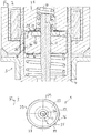
- Figure 3 shows a cross section of parts of the valve assembly 3 along a plane including the upper retaining element 24.
- a number of flow passages 39 are formed by flattened sections of the outer surface 35, extending from the upper side 27 of the armature 23 to the lower side 41 of the armature 23.
- fluid can flow from the fluid inlet portion 5 towards the fluid outlet portion 7, when the injection valve 1 is open.
- the armature 23 When the actuator unit is de-energized in a closed configuration of the valve assembly 3, the armature 23 is in form-fit engagement with the upper armature retainer 24 due to an armature return spring which biases the armature 23 in axial direction towards the upper armature retainer 24.
- the solenoid 21 When the solenoid 21 is energized, the armature 23 experiences a magnetic force and slides upwards - i.e. in axial direction towards the pole piece 25. Due to the form-fit connection with the upper armature retainer 24, it takes the valve needle 11 with it in axial direction away from the fluid outlet portion 7, thereby compressing the calibration spring 18. Consequently, the valve needle 11 moves in axial direction out of the closing position of the valve 1.
- Fuel starts to flow from a central opening of the pole piece 25 in radial outward direction along the upper armature retainer 24 and the upper surface 27 of the armature 23 and, because there are no passages formed on the inside of the armature 23, to the outer surface 35 of the armature 23. There, the fuel flows further along the passages 39 in the outer surface 35 of the armature 23 and towards the fluid outlet portion 7.
- the residual gap between the upper side 27 of the armature 23 and the lower side 31 of the pole piece 25 decreases.
- the decreasing hydraulic diameter of the residual gap effects an increasing pressure difference between the upper side 27 and the lower side 41 of the armature 23.
- the pressure difference generates a hydraulic force on the armature 23 in axial direction away from the pole piece 25.
- the magnetic force of the actuator unit 19 and the spring force of the calibration spring 18 are adapted to the hydraulic force which is generated under normal operating conditions of the injection valve 1 that the spring force and the hydraulic force exceed the magnetic force before the residual gap is completely closed.
- the armature 23 stops moving upwards before contact with the pole piece 25 is made.
- a residual gap is still present between the upper side 27 of the armature 23 and the lower side 31 of the pole piece 25.
- the residual gap stays open because of the hydraulic force the fuel exerts on the upper side 27 of the armature 23 and the upper side 29 of the upper armature retainer 24. Consequently, there is no hard stop for the armature 23 in the maximum opening position.
- the armature 23 is suspended in the maximum opening position by an equilibrium of forces in a stable position.
- a magnetic force acting in a direction away from the fluid outlet portion 7 is balanced by the sum of a hydraulic force and a spring force exerted by the calibration spring 18 both acting in a direction towards the fluid outlet portion 7.
- the calibration spring 18 is able to force the valve needle 11 to move in axial direction into its closing position.
Abstract
A valve assembly (3) for an injection valve (1) is disclosed. It comprises a valve body (4) with a central longitudinal axis (L), a valve needle (11) received in a cavity (9) of the valve body (4) and an armature (23) of an electro-magnetic actuator unit (19) being operable to actuate the valve needle (11). At least one guiding surface (36) on an outer surface (35) of the armature (23) interacts with an inner surface (37) of the valve body (4) to guide the axial movement of the armature (23) and a plurality of flow passages (39) are formed in the outer surface (35) of the armature (23).
Description
- The present invention relates to a valve assembly for a fluid injection valve and to a fluid injection valve, e.g. a fuel injection valve of a vehicle. It particularly relates to solenoid injection valves.
- Such injection valves must be able to dose fluids even in the case of high fuel pressure. One possible design to ensure this is the "free-lift" design, which is disclosed e.g. in document
WO 2015/052281 A1 . According to this design, the armature of the electro-magnetic actuator unit travels about a "pre-stroke gap" or "free-lift gap" before it engages the needle to open the injector. Thus, kinetic energy is accumulated before the actual opening. - Injection valves of the "free lift"-design as well as those without free-lift gap usually have a chrome plating on surfaces of the armature contacting the pole piece to improve wear resistance. However, the chrome plating is costly and should be avoided for environmental reasons.
- There are alternative designs of injection valves, which eliminate contact between the armature and the pole piece. These "contactless designs" or "no hard stop"-designs make use of a high-stiffness spring to stop the armature during opening transient before it hits the pole piece. However, the high-stiffness spring requires installation space and can be costly.
- It is an object of the present disclosure to provide a valve assembly for an injection valve and an injection valve that overcome the above mentioned difficulties and/or provide a stable performance with a high maximum pressure.
- These objects are achieved by means of a valve assembly according to the independent claim.
- Advantageous embodiments and developments of the valve assembly and the injection valve are specified in the dependent claims, the following description and the drawings.
- According to a first aspect of the present disclosure, a valve assembly for an injection valve is specified. It comprises a valve body with a central longitudinal axis. The valve body comprises a cavity with a fluid inlet portion and a fluid outlet portion.
- The valve assembly further comprises a valve needle which is received in the cavity. The valve needle is axially moveable relative to the valve body. The valve needle prevents a fluid flow through the fluid outlet portion in a closing position and releases the fluid flow through the fluid outlet portion in further positions. In particular, the valve needle is axially displaceable relative to the valve body away from the closing position for releasing the fluid flow. The valve assembly may expediently comprise a calibration spring which biases the valve needle towards closing position, i.e. in axial direction towards the fluid outlet portion in the case of an inward opening valve assembly.
- The valve assembly further comprises an armature of an electro-magnetic actuator unit. The armature is operable to actuate the valve needle. In particular, the armature is axially displaceable in reciprocating fashion relative to the valve body and is configured for axially displacing the valve needle away from the closing position, in particular against the bias of the calibration spring. The armature is preferably mechanically coupled to the valve needle in such fashion that it takes the valve needle with it when it moves towards a stationary pole piece of the actuator unit.
- At least one guiding surface is provided on an outer surface of the armature. This means in particular that the outer surface of the armature has a section which represents the guiding surface. The guiding surface interacts with an inner surface of the valve body to guide the axial movement of the armature. In particular, the guiding surface is in sliding mechanical contact with the inner surface of the valve body. The "outer surface" of the armature is in particular understood in the present context to be an external surface of the armature, in particular an external circumferential surface of the armature. In particular, the outer surface delimits the armature laterally in radial outward direction. Thus, the outer surface is in particular the surface of the armature opposing the inner surface of the valve body. The inner surface of the valve body in particular defines the cavity.
- A plurality of flow passages are formed in the outer surface of the armature. The flow passages may expediently extend axially along the armature at its periphery, i.e. at the external surface opposing the inner surface of the valve body. In particular, the outer surface has recessed further sections. The recessed further sections may expediently be spaced apart from the inner surface of the valve body to define the flow passages.
- In a preferred embodiment, the armature has a plurality of guiding surfaces which are spaced apart from one another in circumferential direction. In particular, the guiding surfaces are separated from one another in circumferential direction by the flow passages.
- Expediently, the armature may be have an internal circumferential surface which is fixed to or in sliding mechanical contact with the valve needle for axially guiding the valve needle. Preferably, any portions of the valve needle which are axially overlapping the armature or which are arranged subsequent to the armature in axial direction towards the pole piece are radially spaced apart from the valve body and any elements of the valve assembly which are positionally fix relative to the valve body.
- With advantage, the armature-needle- subassembly is guided by the guiding surface on the outer surface of the armature and not by valve needle or by an armature retainer which is fixed to the valve needle. The flow passages at the periphery of the armature can be manufactured particularly simply and cost-efficiently. The guiding surfaces on the outer surface of the armature are manufacturable with particular small tolerances, allowing a particularly precise axial guidance of the armature.
- According to one embodiment, the armature is fixed to the valve needle. In another embodiment, the armature has an axial play with respect to the valve needle. In this case, the valve assembly may expediently comprise an upper armature retainer which is fixed to the valve needle. The armature is in particular configured to actuate the valve needle by engaging the upper armature retainer. In other words, the armature is operable to take the valve needle with it on its travel in axial direction towards the pole piece by means of form-fit engagement with the upper armature retainer. That the armature retainer is an "upper" armature retainer means in particular that it is operable to limit axial displaceability of the armature with respect to the valve needle in direction towards the pole piece. The calibration spring may be seated against the upper armature retainer. It is also conceivable that it is seated against the valve needle. In embodiments in which the armature is fixed to the valve needle, the calibration spring may also be seated against the armature.
- According to one embodiment, the armature retainer is arranged inside a recess in the upper surface of the armature. In one development, an upper side of the upper armature retainer is coplanar or at least essentially coplanar with the upper surface of the armature. The upper surface of the armature is in particular the surface of the armature which is facing in axial direction towards the pole piece. Preferably, it is a planar surface which extends radially from the outer circumferential contour of the upper armature retainer to the outer surface of the armature. This is possible, because guidance of the valve needle is not effected by way of the upper armature retainer. A radial flow path with particularly small turbulences is achievable in this way.
- According to one embodiment, the flow passages provided in the outer surface are flattened surface sections extending in axial direction from the upper side of the armature to a lower side of the armature. The lower side is understood to be the surface opposite the upper side of the armature, facing towards the fluid outlet portion in case of an inward opening valve. The lower side is in particular facing away from the pole piece.
- This embodiment has the advantage, that the flow passages can be very easily formed during manufacture of the armature by flattening the cylindrical surface of the armature in some places by a suitable process.
- According to one embodiment, the armature is solid and in particular does not comprise fuel passages on the inside. In particular, the upper surface of the armature, extending radially outward from the valve needle or from the upper armature retainer to the outer surface of the armature is unperforated. That the armature does not comprise fuel passages on the inside means in particular that the armature has no through-hole or it has one, and only one, axial through-hole, the valve needle extending through said through-hole.
- The injection valve has the advantage, that it enables a no-hard-stop-concept and therefore eliminates the necessity of a hardening coating on the pole piece and the upper side of the armature. This is due to the fact that the only flow path is built by the flow passages on the outer surface of the armature. Fluid does not flow in passages inside the armature, for no such passages on the inside are provided. As a consequence, during an opening phase of the injector, there is a pressure gradient across the upper side of the armature, suspending the armature in a stable position and building up a sufficient hydraulic force to stop the armature from contacting the pole piece. Thus, fluid can pass between the lower side of the pole piece and the upper side of the armature. In this way, a stable suspended stop position for the armature is achievable. The spring rate of the calibration spring is in particular adapted to the magnetic force of the actuator unit in such fashion that the spring force of the calibration spring alone is smaller than the magnetic force on the armature during operation of the actuator unit. Such a comparatively small spring rate may be advantageous for the dynamic behavior of the valve assembly. Due to the valve assembly having only flow paths along the passages on the outside of the armature, the spring force of the calibration spring is supplemented by the hydraulic force generated by the pressure drop along the radial flow path along the upper surface of the armature. This leads to suspension of the armature in the maximum opening position of the valve assembly at a distance from the pole piece.
- In this way, a monotonous and preferably linear dependence of the amount of fuel which is dispensed by the valve assembly during one injection event on the valve opening time is achievable. The valve opening time is in particular the amount of time for which a coil of the actuator unit is energized during one injection event for actuating the valve needle. Conventional valve assembly usually exhibit an S-shaped "wiggle" and a change of slope in the region of valve opening times at the transition from a ballistic operation mode to an operation mode where the armature hits the pole piece during the injection event. In this context a "ballistic operation mode" is an operation mode for injecting small amounts of fluid in which the coil is energized for such a short time that the valve needle does not reach its fully open position before it starts returning to the closing position.
- An anti-friction coating may be provided on the at least one guiding surface on the outer surface of the armature. The anti-friction coating may in particular comprise tungsten carbon carbide (WCC) or diamond-like carbon (DLC). The coating has the advantage, that it reduces noise, wear and facilitates guidance of the valve needle.
- According to a further aspect of the present disclosure, a fluid injection valve with the valve assembly according to at least one of the embodiments described above is provided. The injection valve may in particular be a fuel injection valve of a vehicle. Preferably, the valve assembly if the fluid injection valve has a solid armature which is free of internal flow channels as described above.
- The injection valve has the advantage of a very high shot-to-shot repeatability compared to an injection valve employing a hard-stop-concept. It has the further advantages, that because contact between the armature and the pole piece is avoided, noise and wear can be reduced and a chrome plating on the pole piece and on the upper side of the armature can be omitted.
- According to one embodiment, during an injection, a fuel delivery is linear over time. A linear and monotonic fuel delivery may be achievable by the hydraulic force of the fluid flow controlling the suspension of the armature. This leads to better control over fuel delivery and higher accuracy of fuel delivery.
- Further advantages, advantageous embodiments and developments of the valve assembly for an injection valve and the fluid injection valve will become apparent from the exemplary embodiments which are described below in association with the schematic figures.
- Figure 1
- shows a longitudinal section of an injection valve according to one embodiment of the invention,
- Figure 2
- shows a detail of
figure 1 and - Figure 3
- shows a cross section of the valve assembly of the injection valve according to
figures 1 and2 . - The fluid injection valve 1 shown in
figures 1 and2 is in particular suitable for dosing fuel to a combustion engine, preferably for dosing fuel directly into a combustion chamber of the engine. However, the invention could be used in other types of injection valves, too. - The injection valve 1 comprises a valve assembly 3. The valve assembly 3 comprises a
valve body 4 with a central longitudinal axis L. Ahousing 6 is partially arranged around thevalve body 4. - The
valve body 4 is hollow so as to define acavity 9. Thecavity 9 has afluid outlet portion 7. Thefluid outlet portion 7 communicates with afluid inlet portion 5 which is provided in thevalve body 4. Thefluid inlet portion 5 and thefluid outlet portion 7 are in particular positioned at opposite axial ends of thevalve body 4. Thecavity 9 takes in avalve needle 11. Thevalve needle 11 comprises a needle shaft and a sealingball 12 welded to the tip of the needle shaft. - Adjacent to an axial end of the needle shaft remote from the sealing
ball 12, an upper armature retainer 24is fixedly coupled to thevalve needle 11. Theupper armature retainer 24 is welded to the needle shaft in the present embodiment. - In a closing position of the
valve needle 11, it sealingly rests on aseat plate 14 having at least one injection nozzle. Thefluid outlet portion 7 is arranged near theseat plate 14. In the closing position of thevalve needle 11, a fluid flow through the at least one injection nozzle is prevented. The injection nozzle may be, for example, an injection hole. However, it may also be of some other type suitable for dosing fluid. - A
preloaded calibration spring 18 exerts a force on thevalve needle 11, biasing thevalve needle 11 towards the closing position. One axial end of thecalibration spring 18 is seated against the upper armature retainer for transferring the spring force of thecalibration spring 18 to thevalve needle 11. - The injection valve 1 is provided with an electro-
magnetic actuator unit 19 to actuate thevalve needle 11. The electro-magnetic actuator unit 19 comprises asolenoid 21, i.e. an electromagnetic coil, which is preferably arranged inside thehousing 6. Furthermore, the electro-magnetic actuator unit 19 comprises anarmature 23. Theactuator unit 19 further comprises apole piece 25. Thehousing 6, parts of thevalve body 4, thepole piece 25 and thearmature 23 form an electromagnetic circuit. - The
pole piece 25 is fixed to thevalve body 4, in particular inside thecavity 9, in the present embodiment. It can also be in one piece with thevalve body 4. Thearmature 23 is arranged in thecavity 9 of thevalve boy 4. It is axially displaceable in reciprocating fashion relative to thevalve body 4. In this way, thepole piece 25 and thearmature 23 represent a stationary core and a movable core, respectively, of theactuator unit 19. - The
armature 23 has a central axial opening through which the shaft of thevalve needle 11 extends. Theneedle 11 is axially guided by the central axial opening in thearmature 23. In particular, a circumferential surface of the shaft and the surface of the central axial opening are in sliding mechanical contact. Thearmature 23 is axially movable relative to thevalve needle 11, i.e. it may slide on theneedle 11. Axial displaceability of thearmature 23 relative to thevalve needle 11 in direction towards thepole piece 25 is limited by theupper armature retainer 24, herein also denoted as "upper retaining element". - A substantially planar, radially extending upper side 27 of the armature 23 - also denoted herein as "upper surface" of the armature 23 - is facing towards a lower side 31 of the
pole piece 25. Theupper retaining element 24 is embedded into arecess 33 in thearmature 23 so that the upper side 27 of thearmature 23 and an upper side 29 of the upper retainingelement 24 are coplanar. - The armature-needle-subassembly is not guided via the upper retaining
element 24. Instead, at least a part of theouter surface 35 of thearmature 23 serves as a guidingsurface 36 interacting with aninner surface 37 of thevalve body 4. -
Figure 3 shows a cross section of parts of the valve assembly 3 along a plane including the upper retainingelement 24. Along theouter surface 35 of thearmature 23, a number offlow passages 39 are formed by flattened sections of theouter surface 35, extending from the upper side 27 of thearmature 23 to thelower side 41 of thearmature 23. Along thoseflow passages 39, fluid can flow from thefluid inlet portion 5 towards thefluid outlet portion 7, when the injection valve 1 is open. - When the actuator unit is de-energized in a closed configuration of the valve assembly 3, the
armature 23 is in form-fit engagement with theupper armature retainer 24 due to an armature return spring which biases thearmature 23 in axial direction towards theupper armature retainer 24. When thesolenoid 21 is energized, thearmature 23 experiences a magnetic force and slides upwards - i.e. in axial direction towards thepole piece 25. Due to the form-fit connection with theupper armature retainer 24, it takes thevalve needle 11 with it in axial direction away from thefluid outlet portion 7, thereby compressing thecalibration spring 18. Consequently, thevalve needle 11 moves in axial direction out of the closing position of the valve 1. - Fuel starts to flow from a central opening of the
pole piece 25 in radial outward direction along theupper armature retainer 24 and the upper surface 27 of thearmature 23 and, because there are no passages formed on the inside of thearmature 23, to theouter surface 35 of thearmature 23. There, the fuel flows further along thepassages 39 in theouter surface 35 of thearmature 23 and towards thefluid outlet portion 7. - As the
armature 23 approaches thepole piece 25, the residual gap between the upper side 27 of thearmature 23 and the lower side 31 of thepole piece 25 decreases. The decreasing hydraulic diameter of the residual gap effects an increasing pressure difference between the upper side 27 and thelower side 41 of thearmature 23. The pressure difference generates a hydraulic force on thearmature 23 in axial direction away from thepole piece 25. The magnetic force of theactuator unit 19 and the spring force of thecalibration spring 18 are adapted to the hydraulic force which is generated under normal operating conditions of the injection valve 1 that the spring force and the hydraulic force exceed the magnetic force before the residual gap is completely closed. - Therefore, the
armature 23 stops moving upwards before contact with thepole piece 25 is made. Thus, in a maximum opening position of the valve 1, in which theneedle 11 has travelled furthest upwards away from thefluid outlet portion 7, a residual gap is still present between the upper side 27 of thearmature 23 and the lower side 31 of thepole piece 25. The residual gap stays open because of the hydraulic force the fuel exerts on the upper side 27 of thearmature 23 and the upper side 29 of theupper armature retainer 24. Consequently, there is no hard stop for thearmature 23 in the maximum opening position. - In fact, the
armature 23 is suspended in the maximum opening position by an equilibrium of forces in a stable position. In the maximum opening position, a magnetic force acting in a direction away from thefluid outlet portion 7 is balanced by the sum of a hydraulic force and a spring force exerted by thecalibration spring 18 both acting in a direction towards thefluid outlet portion 7. - When the
solenoid 21 is de-energized, thecalibration spring 18 is able to force thevalve needle 11 to move in axial direction into its closing position.
Claims (8)
- Valve assembly (3) for an injection valve (1), comprising- a valve body (4) with a central longitudinal axis (L) comprising a cavity (9) with a fluid inlet portion (5) and a fluid outlet portion (7),- a valve needle (11) received in the cavity (9), the valve needle (11) preventing a fluid flow through the fluid outlet portion (7) in a closing position and axially displaceable relative to the valve body (4) for releasing the fluid flow through the fluid outlet portion (7) in further positions,- a calibration spring (18) biasing the valve needle (11) towards the closing position; and- an armature (23) of an electro-magnetic actuator unit (19) being operable to actuate the valve needle (11); wherein the armature (23) comprises- at least one guiding surface (36) on an outer surface (35) of the armature (23), the guiding surface (36) interacting with an inner surface (37) of the valve body (4) to guide the axial movement of the armature (23) and- a plurality of flow passages (39) formed in the outer surface (35) of the armature (23).
- Valve assembly (3) according to the preceding claim comprising a plurality of guiding surfaces (36), wherein the outer surface (35) is an external circumferential surface of the armature (23) having a plurality of sections representing the guiding surfaces (36) and a plurality of further sections representing the flow passages (39), the guiding surfaces (36) being separated from one another in circumferential direction by the flow passages (39).
- Valve assembly (3) according to the one of the preceding claims, further comprising an upper armature retainer (24) which is fixed to the valve needle (11), wherein the armature (23) actuates the valve needle (11) by engaging the upper armature retainer (24) and wherein an upper side (29) of the upper armature retainer (24) is coplanar with an upper side (27) of the armature (23).
- Valve assembly (3) according to one of the preceding claims, wherein the flow passages (39) provided in the outer surface (35) are flattened surface sections extending in axial direction from the upper side (27) of the armature (23) to a lower side (41) of the armature (23).
- Valve assembly (3) according to one of the preceding claims, wherein the armature (23) is solid and does not comprise fuel passages on the inside.
- Valve assembly (3) according to one of the preceding claims, wherein an anti-friction coating is provided on the at least one guiding surface (36) on the outer surface (35) of the armature (23).
- Fluid injection valve (1) with a valve assembly (3) according to one of the preceding claims.
- Fluid injection valve (1) according to the preceding claim, wherein during an injection, a fuel delivery is linear over time.
Priority Applications (1)
| Application Number | Priority Date | Filing Date | Title |
|---|---|---|---|
| EP16206540.3A EP3339626A1 (en) | 2016-12-23 | 2016-12-23 | Valve assembly comprising an armature with guiding surfaces and flow passages and injection valve |
Applications Claiming Priority (1)
| Application Number | Priority Date | Filing Date | Title |
|---|---|---|---|
| EP16206540.3A EP3339626A1 (en) | 2016-12-23 | 2016-12-23 | Valve assembly comprising an armature with guiding surfaces and flow passages and injection valve |
Publications (1)
| Publication Number | Publication Date |
|---|---|
| EP3339626A1 true EP3339626A1 (en) | 2018-06-27 |
Family
ID=57590411
Family Applications (1)
| Application Number | Title | Priority Date | Filing Date |
|---|---|---|---|
| EP16206540.3A Withdrawn EP3339626A1 (en) | 2016-12-23 | 2016-12-23 | Valve assembly comprising an armature with guiding surfaces and flow passages and injection valve |
Country Status (1)
| Country | Link |
|---|---|
| EP (1) | EP3339626A1 (en) |
Citations (7)
| Publication number | Priority date | Publication date | Assignee | Title |
|---|---|---|---|---|
| US6062499A (en) * | 1997-07-02 | 2000-05-16 | Honda Giken Kogyo Kabushiki Kaisha | Injector |
| JP2002310030A (en) * | 2001-04-12 | 2002-10-23 | Denso Corp | Fuel injector |
| DE10246230A1 (en) * | 2002-10-04 | 2004-04-29 | Robert Bosch Gmbh | Injector and process for its manufacture |
| US20060011751A1 (en) * | 2001-09-05 | 2006-01-19 | Thomas Sebastian | Fuel injection valve |
| US20130206872A1 (en) * | 2012-02-15 | 2013-08-15 | Robert Bosch Gmbh | Fuel injector |
| US20130221138A1 (en) * | 2012-02-29 | 2013-08-29 | Robert Bosch Gmbh | Fuel injector |
| WO2015052281A1 (en) | 2013-10-10 | 2015-04-16 | Continental Automotive Gmbh | Injector for a combustion engine |
-
2016
- 2016-12-23 EP EP16206540.3A patent/EP3339626A1/en not_active Withdrawn
Patent Citations (7)
| Publication number | Priority date | Publication date | Assignee | Title |
|---|---|---|---|---|
| US6062499A (en) * | 1997-07-02 | 2000-05-16 | Honda Giken Kogyo Kabushiki Kaisha | Injector |
| JP2002310030A (en) * | 2001-04-12 | 2002-10-23 | Denso Corp | Fuel injector |
| US20060011751A1 (en) * | 2001-09-05 | 2006-01-19 | Thomas Sebastian | Fuel injection valve |
| DE10246230A1 (en) * | 2002-10-04 | 2004-04-29 | Robert Bosch Gmbh | Injector and process for its manufacture |
| US20130206872A1 (en) * | 2012-02-15 | 2013-08-15 | Robert Bosch Gmbh | Fuel injector |
| US20130221138A1 (en) * | 2012-02-29 | 2013-08-29 | Robert Bosch Gmbh | Fuel injector |
| WO2015052281A1 (en) | 2013-10-10 | 2015-04-16 | Continental Automotive Gmbh | Injector for a combustion engine |
Similar Documents
| Publication | Publication Date | Title |
|---|---|---|
| EP2318686B1 (en) | Fuel injector servovalve | |
| EP2771562B1 (en) | Valve assembly for an injection valve and injection valve | |
| EP3353407B1 (en) | Valve assembly for an injection valve and injection valve | |
| US9995262B2 (en) | Fluid injection valve | |
| US10550809B2 (en) | Valve assembly for an injection valve and injection valve | |
| EP2837813B1 (en) | Valve assembly for an injection valve and injection valve | |
| KR20190097052A (en) | Fluid metering valve | |
| EP3339628A1 (en) | Valve assembly for an injection valve and injection valve | |
| CN107923354B (en) | Valve for metering a fluid | |
| EP3339626A1 (en) | Valve assembly comprising an armature with guiding surfaces and flow passages and injection valve | |
| EP3061963A1 (en) | Valve assembly with a guide element | |
| EP3279462B1 (en) | Filter assembly for an injection valve, valve assembly and injection valve | |
| EP3156638B1 (en) | Fuel injector | |
| EP3339627B1 (en) | Valve assembly and fluid injection valve | |
| KR102170838B1 (en) | Valve assembly for injection valve and injection valve | |
| EP3636911A1 (en) | Valve assembly for an injection valve and fuel injection valve | |
| EP3287632A1 (en) | Valve assembly for an injection valve and injection valve | |
| US20100019071A1 (en) | Fuel injector armature guide | |
| EP3611368A1 (en) | Valve assembly and fuel injection valve | |
| WO2017041979A2 (en) | Fluid injection valve | |
| EP3047134A1 (en) | Valve assembly for an injection valve and injection valve |
Legal Events
| Date | Code | Title | Description |
|---|---|---|---|
| PUAI | Public reference made under article 153(3) epc to a published international application that has entered the european phase |
Free format text: ORIGINAL CODE: 0009012 |
|
| AK | Designated contracting states |
Kind code of ref document: A1 Designated state(s): AL AT BE BG CH CY CZ DE DK EE ES FI FR GB GR HR HU IE IS IT LI LT LU LV MC MK MT NL NO PL PT RO RS SE SI SK SM TR |
|
| AX | Request for extension of the european patent |
Extension state: BA ME |
|
| STAA | Information on the status of an ep patent application or granted ep patent |
Free format text: STATUS: THE APPLICATION IS DEEMED TO BE WITHDRAWN |
|
| 18D | Application deemed to be withdrawn |
Effective date: 20190103 |