EP3464863B1 - Closed cycle regenerative heat engines - Google Patents
Closed cycle regenerative heat engines Download PDFInfo
- Publication number
- EP3464863B1 EP3464863B1 EP17732992.7A EP17732992A EP3464863B1 EP 3464863 B1 EP3464863 B1 EP 3464863B1 EP 17732992 A EP17732992 A EP 17732992A EP 3464863 B1 EP3464863 B1 EP 3464863B1
- Authority
- EP
- European Patent Office
- Prior art keywords
- displacer
- resiliently deformable
- closed cycle
- working fluid
- regenerative heat
- Prior art date
- Legal status (The legal status is an assumption and is not a legal conclusion. Google has not performed a legal analysis and makes no representation as to the accuracy of the status listed.)
- Active
Links
Images





Classifications
-
- F—MECHANICAL ENGINEERING; LIGHTING; HEATING; WEAPONS; BLASTING
- F02—COMBUSTION ENGINES; HOT-GAS OR COMBUSTION-PRODUCT ENGINE PLANTS
- F02G—HOT GAS OR COMBUSTION-PRODUCT POSITIVE-DISPLACEMENT ENGINE PLANTS; USE OF WASTE HEAT OF COMBUSTION ENGINES; NOT OTHERWISE PROVIDED FOR
- F02G1/00—Hot gas positive-displacement engine plants
- F02G1/04—Hot gas positive-displacement engine plants of closed-cycle type
- F02G1/043—Hot gas positive-displacement engine plants of closed-cycle type the engine being operated by expansion and contraction of a mass of working gas which is heated and cooled in one of a plurality of constantly communicating expansible chambers, e.g. Stirling cycle type engines
- F02G1/053—Component parts or details
-
- F—MECHANICAL ENGINEERING; LIGHTING; HEATING; WEAPONS; BLASTING
- F02—COMBUSTION ENGINES; HOT-GAS OR COMBUSTION-PRODUCT ENGINE PLANTS
- F02G—HOT GAS OR COMBUSTION-PRODUCT POSITIVE-DISPLACEMENT ENGINE PLANTS; USE OF WASTE HEAT OF COMBUSTION ENGINES; NOT OTHERWISE PROVIDED FOR
- F02G1/00—Hot gas positive-displacement engine plants
- F02G1/04—Hot gas positive-displacement engine plants of closed-cycle type
- F02G1/043—Hot gas positive-displacement engine plants of closed-cycle type the engine being operated by expansion and contraction of a mass of working gas which is heated and cooled in one of a plurality of constantly communicating expansible chambers, e.g. Stirling cycle type engines
-
- F—MECHANICAL ENGINEERING; LIGHTING; HEATING; WEAPONS; BLASTING
- F02—COMBUSTION ENGINES; HOT-GAS OR COMBUSTION-PRODUCT ENGINE PLANTS
- F02G—HOT GAS OR COMBUSTION-PRODUCT POSITIVE-DISPLACEMENT ENGINE PLANTS; USE OF WASTE HEAT OF COMBUSTION ENGINES; NOT OTHERWISE PROVIDED FOR
- F02G1/00—Hot gas positive-displacement engine plants
- F02G1/04—Hot gas positive-displacement engine plants of closed-cycle type
- F02G1/043—Hot gas positive-displacement engine plants of closed-cycle type the engine being operated by expansion and contraction of a mass of working gas which is heated and cooled in one of a plurality of constantly communicating expansible chambers, e.g. Stirling cycle type engines
- F02G1/053—Component parts or details
- F02G1/0535—Seals or sealing arrangements
-
- F—MECHANICAL ENGINEERING; LIGHTING; HEATING; WEAPONS; BLASTING
- F02—COMBUSTION ENGINES; HOT-GAS OR COMBUSTION-PRODUCT ENGINE PLANTS
- F02G—HOT GAS OR COMBUSTION-PRODUCT POSITIVE-DISPLACEMENT ENGINE PLANTS; USE OF WASTE HEAT OF COMBUSTION ENGINES; NOT OTHERWISE PROVIDED FOR
- F02G2243/00—Stirling type engines having closed regenerative thermodynamic cycles with flow controlled by volume changes
- F02G2243/02—Stirling type engines having closed regenerative thermodynamic cycles with flow controlled by volume changes having pistons and displacers in the same cylinder
-
- F—MECHANICAL ENGINEERING; LIGHTING; HEATING; WEAPONS; BLASTING
- F02—COMBUSTION ENGINES; HOT-GAS OR COMBUSTION-PRODUCT ENGINE PLANTS
- F02G—HOT GAS OR COMBUSTION-PRODUCT POSITIVE-DISPLACEMENT ENGINE PLANTS; USE OF WASTE HEAT OF COMBUSTION ENGINES; NOT OTHERWISE PROVIDED FOR
- F02G2243/00—Stirling type engines having closed regenerative thermodynamic cycles with flow controlled by volume changes
- F02G2243/02—Stirling type engines having closed regenerative thermodynamic cycles with flow controlled by volume changes having pistons and displacers in the same cylinder
- F02G2243/04—Crank-connecting-rod drives
- F02G2243/06—Regenerative displacers
-
- F—MECHANICAL ENGINEERING; LIGHTING; HEATING; WEAPONS; BLASTING
- F02—COMBUSTION ENGINES; HOT-GAS OR COMBUSTION-PRODUCT ENGINE PLANTS
- F02G—HOT GAS OR COMBUSTION-PRODUCT POSITIVE-DISPLACEMENT ENGINE PLANTS; USE OF WASTE HEAT OF COMBUSTION ENGINES; NOT OTHERWISE PROVIDED FOR
- F02G2253/00—Seals
- F02G2253/04—Displacer seals
-
- F—MECHANICAL ENGINEERING; LIGHTING; HEATING; WEAPONS; BLASTING
- F02—COMBUSTION ENGINES; HOT-GAS OR COMBUSTION-PRODUCT ENGINE PLANTS
- F02G—HOT GAS OR COMBUSTION-PRODUCT POSITIVE-DISPLACEMENT ENGINE PLANTS; USE OF WASTE HEAT OF COMBUSTION ENGINES; NOT OTHERWISE PROVIDED FOR
- F02G2258/00—Materials used
-
- F—MECHANICAL ENGINEERING; LIGHTING; HEATING; WEAPONS; BLASTING
- F02—COMBUSTION ENGINES; HOT-GAS OR COMBUSTION-PRODUCT ENGINE PLANTS
- F02G—HOT GAS OR COMBUSTION-PRODUCT POSITIVE-DISPLACEMENT ENGINE PLANTS; USE OF WASTE HEAT OF COMBUSTION ENGINES; NOT OTHERWISE PROVIDED FOR
- F02G2270/00—Constructional features
- F02G2270/30—Displacer assemblies
-
- F—MECHANICAL ENGINEERING; LIGHTING; HEATING; WEAPONS; BLASTING
- F02—COMBUSTION ENGINES; HOT-GAS OR COMBUSTION-PRODUCT ENGINE PLANTS
- F02G—HOT GAS OR COMBUSTION-PRODUCT POSITIVE-DISPLACEMENT ENGINE PLANTS; USE OF WASTE HEAT OF COMBUSTION ENGINES; NOT OTHERWISE PROVIDED FOR
- F02G2270/00—Constructional features
- F02G2270/55—Cylinders
Definitions
- the invention relates to closed cycle regenerative heat engines.
- a closed cycle regenerative heat engine is an external combustion engine that operates by cyclic heating and cooling of a gaseous working fluid.
- Such engines include a heat exchanger known as a regenerator that is arranged to take heat from the working fluid as the working fluid moves to a cool part of the engine and return the heat to the working fluid when it moves back from the cool part of the engine towards a hot part of the engine at which heat is applied to the working fluid from an external source.
- Such engines are often referred to as Stirling engines.
- JPH055479A discloses a closed cycle regenerative heat engine comprising: a housing defining a chamber; a resiliently deformable displacer housed in said chamber; a shaft connected with said resiliently deformable displacer; and a movable member housed in said chamber.
- the resiliently deformable displacer is a diaphragm secured to said housing and is resiliently deformable in response to movement of said shaft to displace a working fluid between respective heating and cooling locations in said chamber at which heat is input to said working fluid and said working fluid is cooled.
- the movable member is a diaphragm in sealing engagement with said housing and movable in response to pressure changes of said working fluid caused by said heating and cooling of said working fluid to provide a mechanical power.
- a bypass passage external to the housing is provided via which the fluid can move between the heating and cooling locations in response to movement of the displacer diaphragm.
- the invention provides a closed cycle regenerative heat engine as specified in claim 1.
- a closed cycle regenerative heat engine 10 comprises a housing 12 defining a chamber 14 that has a longitudinal axis 16.
- the engine 10 further comprises a displacer 18 to displace a gaseous working fluid in the chamber 14 between respective heating and cooling locations in said chamber at which heat is input to the working fluid and the working fluid is cooled.
- the displacer 18 is secured to the housing 12 and to a shaft 24 that extends along the chamber 14.
- the displacer 18 is resiliently deformable. Deformation of the displacer 18 in response to movement of the shaft 24 causes it to move between the heating location and cooling location to displace the working fluid.
- the chamber 14 is configured to define a displacer compartment 26 that houses the displacer 18 and a piston compartment 28 that houses a power piston 30.
- the displacer and piston compartments 26, 28 are defined by respective end regions of the chamber 14.
- the displacer 18 and power piston 30 are each movable in the axial direction of the chamber 14.
- the displacer and piston compartments 26, 28 are in fluid communication so that working fluid in the chamber 14 can flow between the two compartments.
- the housing 12 comprises a first housing portion 32, a second housing portion 34 and a thermally insulating portion 36 disposed intermediate the first and second housing portions.
- the first housing portion 32 is arranged to receive heat Q IN from a heat source 40 and may be provided with fins or other surface area enhancers to facilitate heat transfer between relatively cool working fluid in the chamber 14 and the heat source.
- the heat source 40 may, for example, comprise one or more solar panels that heat a fluid such as water.
- the first housing portion may, for example, be at least partially surrounded by a body or assembly defining a water jacket supplied with hot water used to heat the first housing portion 32.
- At least a part of the second housing portion 34 is arranged to reject heat Q out from the working fluid in the chamber 14 to an external cold zone 41.
- the second housing portion 34 may be provided with fins or other surface area enhancers to facilitate the transfer of heat from the relatively warmer working fluid to the external cold zone 41.
- the external cold zone 41 may take any form capable of receiving heat from the second housing portion 34 to cool the working fluid in the chamber 14 and may, for example, be ambient air or a cold-water jacket.
- the displacer compartment 26 of the chamber 14 may vary in diameter along at least portions of its length.
- the displacer compartment 26 has two oppositely directed frusto-conical portions 26-1, 26-2, respectively defined by the first and second housing portions 32, 34, and a circular section portion separating the two frusto-conical portions.
- the circular section portion may be defined by the thermally insulating portion 36 of the housing 12.
- the displacer 18 is secured to the housing 12 at, for example, the thermally insulating portion 36 and is movable by deformation into both frusto-conical portions 26-1, 26-2 of the displacer compartment 26.
- the frusto-conical portion 26-1 is defined by the first housing portion 32 (which in use receives heat Q IN from the heat source 40) and the frusto-conical portion 26-2 is defined by the second housing portion 34 (which in use rejects heat Q out to the external cold zone 41) and they are separated by the thermally insulating portion 36, there will be temperature gradient between them. Accordingly, for ease of reference, in the description that follows the frusto-conical portion 26-1 will be referred to as the hot end of the displacer chamber and the frusto-conical portion 26-2 will be referred to as the cold end of the displacer compartment.
- the terms 'hot' and 'cold' are used in a relative sense as convenient labels to indicate that, in use, there is a temperature difference between the two ends of the displacer compartment 26 so that the hot end 26-1 is a location in the chamber 14 at which the working fluid is heated and the cold end 26-2 is a location in the chamber at which the working fluid is cooled and beyond this, the terms should not be interpreted restrictively such as to limit the scope of the invention defined in the claims.
- the piston compartment 28 of the chamber 14 has a constant diameter and is in fluid communication with the displacer compartment 26, for example, via an opening 42 disposed adjacent the narrow end of the frusto-conical cold end 26-2 of the displacer compartment.
- the opening 42 may be defined by the second housing portion 34.
- the shaft 24 extends from the displacer compartment 26 into the piston compartment 28 via the opening 42.
- the shaft 24 passes through an axially extending through-hole provided in the power piston 30 and out of the piston compartment 28.
- the end of the shaft 24 disposed remote from the displacer 18 and outside of the chamber 14 is connected with a flywheel 46.
- the shaft 24 may be connected with the flywheel 46 by a connecting shaft, or link, 48.
- the connection to the flywheel 46 allows the displacer 18 to receive stored mechanical energy from the flywheel to cause the displacer to deform to move working fluid between the hot and cold ends 26-1, 26-2 of the displacer compartment 26.
- the piston 30 is connected with the flywheel 46 by a piston shaft, or link, 50.
- the shafts 24, 50 are connected with the flywheel 46 such that they are 90° out of phase.
- the displacer 18 comprises a volute spring, which in the illustrated example comprises a resilient strip having a first end connected with the shaft 24 and a second and connected with the housing 12.
- the resilient strip winds about the shaft 24 to form a coil having an axis generally coincident with the longitudinal axis 16 of the chamber 14.
- the first end of the resilient strip is fixedly connected with the shaft 24 and the second end is fixedly connected with the thermally insulating portion 36 of the housing 12 so that the displacer 18 is secured to the housing 12 and is forced to deform when the shaft 24 reciprocates in the chamber 14.
- the displacer 18 may deform from the condition shown in Figure 3 to respective first and second conditions in which it at least substantially fills the frusto-conical hot and cold ends 26-1, 26-2 of the displacer compartment 26.
- Examples of the displacer 18 at least substantially filling the respective hot and cold ends 26-1, 26-2 of the displacer compartment 26 can be seen in Figures 5 and 8 .
- This deformation of the displacer 18 causes it to displace working fluid in the displacer compartment 26 to move it between the hot and cold ends 26-1, 26-2 to bring the working fluid into contact with the first and second housing portions 32, 34 to be heated and cooled respectively.
- most of the working fluid is at the hot end 26-1 of the displacer compartment 26 and the power piston 30 is at least substantially at the end of its return stroke at which it is disposed the closest it gets to the displacer compartment.
- the working fluid at the hot end 26-1 receives heat Q IN from the heat source 40.
- the heating of the working fluid causes it to expand.
- the expanding working fluid drives the power piston 30 away from the displacer compartment 26-1 on its power stroke as indicated by the arrow 52 in Figure 5 .
- the outwards translational movement of the power piston 30 is transmitted to the flywheel 46 by the shaft 50 causing the flywheel to rotate clockwise (as viewed in the drawings).
- Figure 6 shows the power piston 30 close to the end of its power stroke at which is disposed the furthest it gets from the displacer compartment 26.
- the momentum of the flywheel 46 provides mechanical energy to cause the displacer 18 to move from cold end 26-2 of the displacer compartment 26 to the hot end 26-1.
- the working fluid is displaced to the cold end 26-2.
- the working fluid does not pass around the displacer 18 as it would in a conventional Stirling engine, but instead passes between the coils of the displacer, which effectively defines at least one through passage through which the working fluid passes as it moves between the hot and cold ends 26-1, 26-2 of the displacer compartment 26.
- the displacer 18 reciprocates in the displacer compartment 26 to move the working fluid between the hot and cold ends 26-1, 26-2 and the power piston 30 reciprocates in the piston compartment 28 in response to the changing pressure of the working fluid as it is heated and cooled to provide a mechanical power output.
- the mechanical power output by the closed cycle regenerative heat engine 10 is delivered to the flywheel 46.
- the mechanical power output may be delivered to a crankshaft or an electric generator.
- Figures 10 and 11 show another example of a closed cycle regenerative heat engine 110.
- Features of the closed cycle regenerative heat engine 110 that are the same as or similar to features of the closed cycle regenerative heat engine 10 are indicated by the same reference numerals incremented by 100 and may not be described in detail again.
- the closed cycle regenerative heat engine 110 comprises a housing 112 defining a chamber that has a displacer compartment 126 and a piston compartment 128.
- a resiliently deformable displacer 118 is housed in the displacer compartment 126.
- a power piston 130 is housed for reciprocating movement in the piston compartment 128.
- the piston compartment 128 is in fluid communication with the displacement compartment 126 so that working fluid heated in the displacement compartment can act on the power piston 130.
- the displacer compartment 126 varies in diameter along its length. In particular, the hot end 126-1 increases in diameter towards the thermally insulating portion 136 and the cold end 126-2 decreases in diameter from the thermally insulating portion towards the piston compartment 128.
- the piston compartment 128 is defined by a thermally insulating portion 136 of the housing 112 that is disposed between a first housing portion 132 at which heat Q IN is input to the chamber to heat the working fluid and a second housing portion 134 at which heat Q OUT is rejected from the chamber to cool the working fluid.
- the first and housing portions 132, 134 may be provided with projections 127-1, 127-2 extending into the displacer compartment 126 at the hot and cold ends 126-1, 126-2 of the compartment.
- the projections 127-1, 127-2 may define respective convoluted passages 129-1, 129-2 into which the displacer 118 moves at it reciprocates between the hot and cold ends 126-1, 126-2 of the displacer compartment 126.
- the projections 127-1, 127-2 may comprising spiralling walls. The projections 127-1.
- the projections 127-1, 127-2 may be configured such that the respective passages 129-1, 129-2 are at least substantially filled when the displacer 118 is at the respective ends of the displacer compartment 126 so that the displacer 118 is able to fill the hot and cold ends 126-1, 126-2.
- the projections 127-1, 127-2 may be integral parts of the first and second housing portions 132, 134 or separate components or assemblies fitted to the respective housing portions.
- the projections 127-1, 127-2 provide additional surface area for heat transfer at the hot and cold ends of the displacer compartment 126, which may improve the efficiency of the heat transfer process.
- the projections 127-1, 127-2 may be hollow. This provides the possibility of flowing a heated fluid, for example hot water, through the projection, or projections, 127-1 at the hot end 126-1 of the displacer compartment 126. Similarly, a cooling fluid, for example cold water, may be flowed through the projection, or projections, 127-2 at the cold end 126-2 of the displacer compartment 126. Providing fluid flow paths extending into the projections 127-1, 127-2 to allow a heating or cooling fluid respectively to flow into the projections may further enhance the efficiency of the heat transfer process.
- a heated fluid for example hot water
- a cooling fluid for example cold water
- the resiliently deformable displacer 118 displaces along a first axis 116 defined by the shaft 124 that is connected to the resiliently deformable displacer and the power piston 130 displaces along a second axis 156 defined by the piston compartment 128 of the chamber.
- the respective reciprocating movements of the resiliently deformable displacer 118 and power piston 130 are mutually perpendicular as indicated by the respective arrows 157, 158. Since the relative displacements of the resiliently deformable displacer 118 and power piston 130 are at 90° to one another, their connections with the flywheel 146, or crankshaft, are in phase and not 90° out of phase as in the closed cycle regenerative heat engine 10.
- the closed cycle regenerative heat engine 110 further comprises a frequency adjustor 160 that is connected with the resiliently deformable displacer 118.
- the frequency adjustor 160 is configured to act on the resiliently deformable displacer to adjust, modify or tune the natural frequency of the displacer 118.
- the frequency adjustor 160 comprises a rocker 162 mounted on a pivot 164.
- the pivot 164 is supported by an arm 166 that may be secured to the housing 112.
- a first end 168 of the rocker 162 is pivotally connected to an end of the shaft 124 via a link 170 and the second end 172 of the rocker is pivotally connected to an end of a link 174.
- the opposite end of the link 174 is connected to the flywheel 146 or a crankshaft connected with the power piston.
- the rocker 162 supports oppositely disposed weights 176, 178.
- the positioning of the weights 176, 178 can be changed to adjust the natural frequency of the displacer 118. Moving the weights 176, 178 radially inwards, towards the pivot 164, increases the natural frequency of the displacer, while moving the weights radially outwardly, away from the pivot 164, decreases its natural frequency. This allows the natural frequency of the displacer 118 to be tuned to match the drive speed of the engine.
- the operation of the closed cycle regenerative heat engine 110 is analogous to the operation of the closed cycle regenerative heat engine 10 as illustrated by Figures 4 to 9 and so will not be described in detail again.
- the displacer 118 of the closed cycle regenerative heat engine 110 fills the hot and cold ends 126-1, 126-2 when it reaches the respective ends of its reciprocating motion between the two ends.
- the housing defines a chamber that has a displacer compartment and a piston compartment that respectively house a resiliently deformable displacer and a power piston.
- the piston compartment is configured to have opposite ends that are shaped to correspond to the deformed shape of the resiliently deformable displacer at each end of its stroke and the two compartments are in fluid communication to allow working fluid heated in the displacer compartment to act on the power piston.
- only one end of the chamber is shaped to correspond to the deformed shape of the resiliently deformable displacer and the crown of the power piston may be provided with a depression shaped to receive the deformed resiliently deformable displacer at one end of its stroke. In such examples, there are no clearly defined displacer and piston compartments since the crown of the power piston effectively forms a wall of a notional displacer compartment.
- the resiliently deformable displacer in the illustrated examples of a closed cycle regenerative heat engine acts as a spring so that the engine can be run at natural frequency, thereby minimising power losses due to reciprocating movement in the engine.
- the resiliently deformable displacer may be configured such that it has relatively low stiffness so that the system has a relatively low natural frequency. This allows for slow engine running. A slow running engine allows more time for heating and cooling of the working fluid, which may allow for greater power delivery.
- the coils of the resiliently deformable displacer may provide a significantly greater surface area than a conventional solid displacer piston allowing it to receive and store significant amounts of heat as the relatively hot working fluid is displaced to the cool end of chamber and return that heat to the relatively cool working fluid as it is displaced to the hot end of the chamber so that the displacer may function as a regenerator.
- Figures 12 and 13 show another example of a closed cycle regenerative heat engine 210.
- Features of the closed cycle regenerative heat engine 210 that are the same as or similar to features of the closed cycle regenerative heat engine 10 are indicated by the same reference numerals incremented by 200 and may not be described in detail again.
- the closed cycle regenerative heat engine 210 comprises a housing 212 defining a chamber that has a displacer compartment 226 having a hot end 226-1 and a cold end 226-2 and a diaphragm compartment 228.
- a resiliently deformable displacer 218 is housed in the displacer compartment 226.
- a diaphragm 230 is housed for reciprocating movement in the diaphragm compartment 228.
- the diaphragm compartment 228 is in fluid communication with the displacement compartment 226 so that working fluid heated in the displacement compartment 226 can act on the diaphragm 230.
- the shaft 224 connected to the displacer 218 is connected with a moving part 247 of a linear electric actuator 246, which in some examples may comprise a voice coil.
- the linear electric actuator 246 is supplied with electric current via a controller 249 such that the electric current causes the moving part 247 to reciprocate.
- the controller 249 may control the supply of electricity such that the moving part 247 may reciprocate at, or close to, the natural frequency of the displacer 218.
- the mechanical energy input to cause the displacer 218 to move between the hot and cold ends 226-1, 226-2 of the displacer compartment 226 is provided by the linear electric actuator 246 and controlled such that the displacer 218 reciprocates between the hot and cold ends 226-1, 226-2 at least substantially at its natural frequency.
- the diaphragm 230 is moved by changes in the pressure of the working fluid to provide a metical energy output of the closed cycle regenerative heat engine 210.
- the mechanical energy output when the diaphragm 230 moves in response to the expansion of the heated working fluid is input to a moving part 280 of a linear electrical generator 282, which in some examples may be a voice coil.
- the diaphragm 230 may be connected to the moving part 280 by an elongate connecting member, or link, 231.
- the connector 231 may comprise a hollow shaft that is clamped to a central region of the diaphragm 230.
- the hollow shaft may receive the end 225 ( Figure 13 ) of the shaft 214 that is located remote from the linear electric motor 246.
- the diaphragm 230 reciprocates causing linear reciprocating movement of the moving part 280, which in turn causes the linear electrical generator 282 to generate an electrical current that may be used to power electrical equipment or charge one or more batteries.
- the resiliently deformable displacer 218 may be an elongate resilient strip comprising a composite structure, laminate structure or assembly, secured to the housing 212 between annular diaphragm mounts 235.
- the displacer 218 may comprise a first resilient coil 218-1, a second resilient coil 218-2 disposed opposite and spaced apart from the first resilient coil and a thermally insulating member 218-3 disposed intermediate and separating the first and second resilient coils.
- the resilient coils 218-1, 218-2 may be made of a metal such as aluminium, or an aluminium alloy.
- the thermally insulating member 218-3 should be capable of withstanding the operating temperatures within the displacer chamber 218 and is preferably an elastomer or polymer that is stable at relatively high temperatures.
- the thermally insulating member 218-3 may comprise a hard rubber or polyether ether ketone (PEEK).
- the provision of a thermally insulating member 218-3 between the resilient coils 218-1, 218-2 may maintain a temperature gradient across the displacer 218 that is greater than is achievable with a conventional one-piece displacer piston so that the temperature of the resilient coil 218-1 disposed in the hot end 226-1 of the displacer compartment 226 stays at least relatively close to the temperature of the hot end 226-1 while the temperature of the resilient coil 228-2 disposed in the cold end 226-2 of the displacer compartment 218 stays at least relatively close to the temperature of the cold end 226-2.
- the resilient coil 218-1 should absorb less of the heat Q IN input at the first housing portion 232.
- the heat transfer from the working fluid at the cold end 226-2 may be enhanced as the resilient coil 218-2 may remain relatively cooler than a conventional one-piece displacer piston operating in similar working conditions
- the displacer compartment 226 varies in diameter along its length.
- the hot end 226-1 increases in diameter towards the thermally insulating portion 236 and the cold end 226-2 decreases in diameter from the thermally insulating portion towards the diaphragm compartment 228.
- the first and housing portions 232, 234 may be provided with projections 227-1, 227-2 extending into the displacer compartment 226 at the hot and cold ends 226-1, 226-2 of the compartment.
- the projections 227-1, 227-2 may define respective convoluted passages 229-1, 229-2 into which the displacer 218 moves as it reciprocates between the hot and cold ends 226-1, 226-2 of the displacer compartment 226.
- the projections 227-1, 227-2 may comprising spiralling walls.
- the resilient coil 218-1 may at least substantially fill the passage 219-1 when the displacer is at the hot end 226-1 of the displacer compartment and the resilient coil 218-2 may at least substantially fill the passage 219-2 when the displacer is at the cold end 226-2.
- the projections 227-1, 227-2 provide additional surface area for heat transfer at the hot and cold ends 226-1. 226-2 of the displacer compartment 226, which may improve the efficiency of the respective heat transfer processes.
- the or each projection 227-1 or the or each projection 227-2 may be hollow to allow the feed of a heating or cooling fluid through the projections as described above in connection with Figure 11 .
- the resilient coils 218-1, 218-2 define respective spiralling channels 221-1, 221-2 that are connected via a spiralling channel 223 provided in the thermally insulating member 236.
- the spiralling channels 221-1, 221-2, 221-3 define a through-passage in the displacer 218 that allows working fluid to pass through the displacer to move between the hot and cold ends 226-1, 226-2 of the displacer compartment 226 as the displacer moves between the hot and cold ends.
- the spiralling channels 221-1, 221-2 may be configured to mate with the projections 227-1, 227-1.
- the displacer compartment may be pressurised to 2 atmospheres (approximately 200kPa).
- the displacer compartment is pre-pressurised, it is desirable to ensure that the pressure on either side of the piston, or diaphragm, is balanced.
- Figures 12 and 13 show a pressurisation system configured to allow pre-pressurisation of the displacer compartment 226. Referring to Figure 12 , a valve 286 is provided in a wall 288 of the housing 212 that partially defines the diaphragm compartment 228.
- the valve 286 may be a one-way valve or, for example, a Schrader valve.
- one or more bypass passages 290 may be provided to bypass the diaphragm 230 and allow working fluid to be pumped into the diaphragm compartment 226 via the valve 286 and diaphragm compartment 228.
- the or each bypass passage 290 may take any convenient form according to the particular configuration of the engine housing.
- a bypass passage 290 comprising a through-hole in an annular housing member 292 disposed between the wall 288 and the second housing portion 234, a recess in an end of the wall 288 that is in flow communication with the upstream end of the through-hole and a recess in the second housing portion 234 that is in flow communication with the downstream end of the through-hole.
- the operation of the closed cycle regenerative heat engine 210 is analogous to the operation of the closed cycle regenerative heat engine 10 as illustrated by Figures 4 to 9 and so will not be described in detail again.
- the displacer 218 of the closed cycle regenerative heat engine 210 fills the hot and cold ends 226-1, 226-2 when it reaches the respective ends of its reciprocating motion between the two ends.
- working fluid pumped in at the valve 286 passes from the diaphragm compartment 228 to the cold end 226-2 of the displacer compartment via the connecting passage 290 and two openings 242 that extend between the displacer compartment and the diaphragm compartment.
- the pumped working fluid is able to flow to the hot end 226-1 of the displacer compartment 226 by passing through the spiralling channels 221-2, 221-2 and apertures 223 of the displacer 218.
- the pumped working fluid is able pass into the compartment 284 that houses the linear electrical actuator 246 via the clearance between the shaft 214 and a bearing 294 that supports the shaft 214.
- the displacer compartment 216, the diaphragm compartment 228 on both sides of the diaphragm 230 and the compartment 246 represent a closed system that can be pre-pressurised to a pressure above atmospheric that is substantially equal throughout the closed system so as not to adversely affect the operation of the moving parts of the engine in the chamber.
- a closed cycle regenerative heat engine embodying one or more of the operating features described above has a resiliently deformable displacer that has a portion anchored and so cannot move and a portion that is connected with a reciprocating shaft. As the shaft reciprocates, the displacer deforms so as to move a working fluid between respective heating and cooling locations in a chamber.
- the shaft may be driven by a flywheel powered by the engine output or an electrical actuator.
- the shaft may reciprocate at or near the natural frequency of the resiliently deformable displacer. This may reduce the input energy needed to operate the displacer and so increase the efficiency of the engine.
- a frequency adjuster may be provided to tune the natural frequency of the displacer to the engine drive speed.
- the working fluid moves between the respective heating and cooling locations, it passes through the resiliently deformable displacer.
- this may significantly increase the surface area of the displacer available for heat exchange with the working fluid.
- the displacer may comprise first and second members, or body parts, separated by thermal insulation.
- One of the first and second members is disposed on the side of the heating location and the other is disposed on the side of the cooling location.
- the effect of the thermally insulating layer may be to prevent, or at least significantly inhibit heat transfer between the first and second members.
- the member on the side of the heating location will be maintained at a relatively higher temperature than the member on the side of the cooling location.
- the first and second members will be maintained at a temperature the same as, or at least closer to, the temperature of the respective heating and cooling locations, thereby potentially increasing the efficiency of the heat transfer processes affecting the working fluid at the heating and cooling locations.
- provision may be made for pre-pressurising the working fluid. This may provide for improved power output.
- a pressurisation system may be provided to allows pressurisation of the working fluid.
- the pressurisation system includes one or more passages or clearances between components to allow the pressurisation to affect all parts of the engine chamber in which moving parts associated with the displacer and power piston or diaphragm are housed so that the pressures acting on those parts are at last substantially balanced.
- the resiliently deformable displacer at least substantially fills the heating and cooling locations when at the ends of its reciprocating movement.
- the resiliently deformable displacer deforms so as to leave substantially no gap between the outer periphery of the displacer and the housing and the internal through-passage through which the working fluid passes as it moves between the heating and cooling locations is closed up.
- the resiliently deformable displacers leave substantially no gap between the outer periphery of the displacer and the housing and the internal through-passage through which the working fluid passes as it moves between the heating and cooling locations is blocked. Blockage of the internal through-passage may be partly due to deformation of the resiliently deformable displacer and partly due to the projections entering the internal through-passage.
- an outer periphery of the displacer may virtually, or actually, engage the housing so that there is no dead space surrounding the displacer. This may increase the efficiency of the closed cycle regenerative heat engine by ensuring that a larger volume of the working fluid is heated and cooled at the heating and cooling locations.
Landscapes
- Engineering & Computer Science (AREA)
- Chemical & Material Sciences (AREA)
- Combustion & Propulsion (AREA)
- Mechanical Engineering (AREA)
- General Engineering & Computer Science (AREA)
- Engine Equipment That Uses Special Cycles (AREA)
- Air-Conditioning For Vehicles (AREA)
Description
- The invention relates to closed cycle regenerative heat engines.
- A closed cycle regenerative heat engine is an external combustion engine that operates by cyclic heating and cooling of a gaseous working fluid. Such engines include a heat exchanger known as a regenerator that is arranged to take heat from the working fluid as the working fluid moves to a cool part of the engine and return the heat to the working fluid when it moves back from the cool part of the engine towards a hot part of the engine at which heat is applied to the working fluid from an external source. Such engines are often referred to as Stirling engines.
- JPH055479A discloses a closed cycle regenerative heat engine comprising: a housing defining a chamber; a resiliently deformable displacer housed in said chamber; a shaft connected with said resiliently deformable displacer; and a movable member housed in said chamber. The resiliently deformable displacer is a diaphragm secured to said housing and is resiliently deformable in response to movement of said shaft to displace a working fluid between respective heating and cooling locations in said chamber at which heat is input to said working fluid and said working fluid is cooled. The movable member is a diaphragm in sealing engagement with said housing and movable in response to pressure changes of said working fluid caused by said heating and cooling of said working fluid to provide a mechanical power. A bypass passage external to the housing is provided via which the fluid can move between the heating and cooling locations in response to movement of the displacer diaphragm.
- The invention provides a closed cycle regenerative heat engine as specified in claim 1.
- In the disclosure that follows, reference will be made to the drawings in which:
-
Figure 1 is side elevation of an example of a closed cycle regenerative heat engine; -
Figure 2 is an end elevation of the closed cycle regenerative heat engine ofFigure 1 ; -
Figure 3 is a section view on line III-III inFigure 1 ; -
Figures 4 to 9 are views corresponding toFigure 3 showing a cycle of the closed regenerative heat engine; -
Figure 10 is a section view of another example of a closed cycle regenerative heat engine; -
Figure 11 is an enlargement of a portion ofFigure 10 ; -
Figure 12 is a section view of another example of a closed cycle regenerative heat engine; and -
Figure 13 is an enlargement of a portion ofFigure 12 . - Referring to
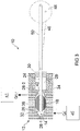
Figures 1 to 3 , a closed cycleregenerative heat engine 10 comprises ahousing 12 defining achamber 14 that has alongitudinal axis 16. Theengine 10 further comprises adisplacer 18 to displace a gaseous working fluid in thechamber 14 between respective heating and cooling locations in said chamber at which heat is input to the working fluid and the working fluid is cooled. Thedisplacer 18 is secured to thehousing 12 and to ashaft 24 that extends along thechamber 14. Thedisplacer 18 is resiliently deformable. Deformation of thedisplacer 18 in response to movement of theshaft 24 causes it to move between the heating location and cooling location to displace the working fluid. - Referring particularly to
Figure 3 , thechamber 14 is configured to define adisplacer compartment 26 that houses thedisplacer 18 and apiston compartment 28 that houses apower piston 30. In the illustrated example the displacer andpiston compartments chamber 14. The displacer 18 andpower piston 30 are each movable in the axial direction of thechamber 14. The displacer andpiston compartments chamber 14 can flow between the two compartments. - The
housing 12 comprises afirst housing portion 32, asecond housing portion 34 and a thermally insulatingportion 36 disposed intermediate the first and second housing portions. Thefirst housing portion 32 is arranged to receive heat QIN from aheat source 40 and may be provided with fins or other surface area enhancers to facilitate heat transfer between relatively cool working fluid in thechamber 14 and the heat source. Theheat source 40 may, for example, comprise one or more solar panels that heat a fluid such as water. The first housing portion may, for example, be at least partially surrounded by a body or assembly defining a water jacket supplied with hot water used to heat thefirst housing portion 32. At least a part of thesecond housing portion 34 is arranged to reject heat Qout from the working fluid in thechamber 14 to an externalcold zone 41. Thesecond housing portion 34 may be provided with fins or other surface area enhancers to facilitate the transfer of heat from the relatively warmer working fluid to the externalcold zone 41. The externalcold zone 41 may take any form capable of receiving heat from thesecond housing portion 34 to cool the working fluid in thechamber 14 and may, for example, be ambient air or a cold-water jacket. - The
displacer compartment 26 of thechamber 14 may vary in diameter along at least portions of its length. In the illustrated example thedisplacer compartment 26 has two oppositely directed frusto-conical portions 26-1, 26-2, respectively defined by the first andsecond housing portions portion 36 of thehousing 12. Thedisplacer 18 is secured to thehousing 12 at, for example, the thermally insulatingportion 36 and is movable by deformation into both frusto-conical portions 26-1, 26-2 of thedisplacer compartment 26. Since the frusto-conical portion 26-1 is defined by the first housing portion 32 (which in use receives heat QIN from the heat source 40) and the frusto-conical portion 26-2 is defined by the second housing portion 34 (which in use rejects heat Qout to the external cold zone 41) and they are separated by the thermally insulatingportion 36, there will be temperature gradient between them. Accordingly, for ease of reference, in the description that follows the frusto-conical portion 26-1 will be referred to as the hot end of the displacer chamber and the frusto-conical portion 26-2 will be referred to as the cold end of the displacer compartment. It is to be understood that the terms 'hot' and 'cold' are used in a relative sense as convenient labels to indicate that, in use, there is a temperature difference between the two ends of thedisplacer compartment 26 so that the hot end 26-1 is a location in thechamber 14 at which the working fluid is heated and the cold end 26-2 is a location in the chamber at which the working fluid is cooled and beyond this, the terms should not be interpreted restrictively such as to limit the scope of the invention defined in the claims. - The
piston compartment 28 of thechamber 14 has a constant diameter and is in fluid communication with thedisplacer compartment 26, for example, via anopening 42 disposed adjacent the narrow end of the frusto-conical cold end 26-2 of the displacer compartment. The opening 42 may be defined by thesecond housing portion 34. Theshaft 24 extends from thedisplacer compartment 26 into thepiston compartment 28 via theopening 42. Theshaft 24 passes through an axially extending through-hole provided in thepower piston 30 and out of thepiston compartment 28. The end of theshaft 24 disposed remote from thedisplacer 18 and outside of thechamber 14 is connected with aflywheel 46. Theshaft 24 may be connected with theflywheel 46 by a connecting shaft, or link, 48. The connection to theflywheel 46 allows thedisplacer 18 to receive stored mechanical energy from the flywheel to cause the displacer to deform to move working fluid between the hot and cold ends 26-1, 26-2 of thedisplacer compartment 26. Thepiston 30 is connected with theflywheel 46 by a piston shaft, or link, 50. Theshafts flywheel 46 such that they are 90° out of phase. - The
displacer 18 comprises a volute spring, which in the illustrated example comprises a resilient strip having a first end connected with theshaft 24 and a second and connected with thehousing 12. The resilient strip winds about theshaft 24 to form a coil having an axis generally coincident with thelongitudinal axis 16 of thechamber 14. In the illustrated example, the first end of the resilient strip is fixedly connected with theshaft 24 and the second end is fixedly connected with the thermally insulatingportion 36 of thehousing 12 so that thedisplacer 18 is secured to thehousing 12 and is forced to deform when theshaft 24 reciprocates in thechamber 14. Since the second end of the resilient strip is fixedly connected with thehousing 12 and the first end moves with theshaft 24 when the shaft reciprocates in thechamber 14, thedisplacer 18 may deform from the condition shown inFigure 3 to respective first and second conditions in which it at least substantially fills the frusto-conical hot and cold ends 26-1, 26-2 of thedisplacer compartment 26. Examples of thedisplacer 18 at least substantially filling the respective hot and cold ends 26-1, 26-2 of thedisplacer compartment 26 can be seen inFigures 5 and8 . This deformation of thedisplacer 18 causes it to displace working fluid in thedisplacer compartment 26 to move it between the hot and cold ends 26-1, 26-2 to bring the working fluid into contact with the first andsecond housing portions - The heating of the working fluid by contact with the
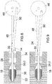
first housing portion 32 causes it to expand. The expansion of the working fluid at the hot end 26-1 drives thepower piston 30 away from thedisplacer compartment 26 on its outward, or power, stroke. The cooling of the working fluid at the cold end 26-2 by contact with thesecond housing portion 34 causes it to contract, allowing thepower piston 30 to move back towards thedisplacer compartment 26 of thechamber 14 on its inward, or return, stroke. The relative displacement of thedisplacer 18 and movement of thepower piston 30 are illustrated byFigures 4 to 9 , which show a full cycle of the closed cycleregenerative heat engine 10. - Referring to
Figure 4 , most of the working fluid is at the hot end 26-1 of thedisplacer compartment 26 and thepower piston 30 is at least substantially at the end of its return stroke at which it is disposed the closest it gets to the displacer compartment. The working fluid at the hot end 26-1 receives heat QIN from theheat source 40. The heating of the working fluid causes it to expand. The expanding working fluid drives thepower piston 30 away from the displacer compartment 26-1 on its power stroke as indicated by thearrow 52 inFigure 5 . The outwards translational movement of thepower piston 30 is transmitted to theflywheel 46 by theshaft 50 causing the flywheel to rotate clockwise (as viewed in the drawings).Figure 6 shows thepower piston 30 close to the end of its power stroke at which is disposed the furthest it gets from thedisplacer compartment 26. At this stage, the momentum of theflywheel 46 provides mechanical energy to cause thedisplacer 18 to move from cold end 26-2 of thedisplacer compartment 26 to the hot end 26-1. As shown inFigure 7 , as thedisplacer 18 moves into the hot end 26-1 of the displacement compartment, the working fluid is displaced to the cold end 26-2. The working fluid does not pass around thedisplacer 18 as it would in a conventional Stirling engine, but instead passes between the coils of the displacer, which effectively defines at least one through passage through which the working fluid passes as it moves between the hot and cold ends 26-1, 26-2 of thedisplacer compartment 26. When at the cold end 26-2, the working fluid rejects heat Qout to theexternal cold zone 41 via thesecond housing portion 34. The cooling of the working fluid at the cold end 26-2 causes it to contract so that thepower piston 30 is drawn inwardly towards thedisplacer compartment 26 as indicated by thearrow 54 inFigures 8 and 9. Figure 9 shows the power piston approaching the end of its return stroke and thedisplacer 18 commencing its movement from the hot end 26-1 towards the cold end 26-2 to return to the position shown inFigure 4 . The mechanical energy to move the displacer from the hot end 26-1 to the cold end 26-2 is provided by theflywheel 46. As thedisplacer 18 moves into the cold end 26-2, the working fluid is again displaced to the hot end 26-1 and the cycle described above repeats. Thus, thedisplacer 18 reciprocates in thedisplacer compartment 26 to move the working fluid between the hot and cold ends 26-1, 26-2 and thepower piston 30 reciprocates in thepiston compartment 28 in response to the changing pressure of the working fluid as it is heated and cooled to provide a mechanical power output. Although not essential, in this example the mechanical power output by the closed cycleregenerative heat engine 10 is delivered to theflywheel 46. In other examples the mechanical power output may be delivered to a crankshaft or an electric generator. -
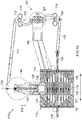
Figures 10 and11 show another example of a closed cycleregenerative heat engine 110. Features of the closed cycleregenerative heat engine 110 that are the same as or similar to features of the closed cycleregenerative heat engine 10 are indicated by the same reference numerals incremented by 100 and may not be described in detail again. - The closed cycle
regenerative heat engine 110 comprises ahousing 112 defining a chamber that has adisplacer compartment 126 and apiston compartment 128. A resilientlydeformable displacer 118 is housed in thedisplacer compartment 126. Apower piston 130 is housed for reciprocating movement in thepiston compartment 128. Thepiston compartment 128 is in fluid communication with thedisplacement compartment 126 so that working fluid heated in the displacement compartment can act on thepower piston 130. As in the previous example, thedisplacer compartment 126 varies in diameter along its length. In particular, the hot end 126-1 increases in diameter towards the thermally insulatingportion 136 and the cold end 126-2 decreases in diameter from the thermally insulating portion towards thepiston compartment 128. In this example, thepiston compartment 128 is defined by a thermally insulatingportion 136 of thehousing 112 that is disposed between afirst housing portion 132 at which heat QIN is input to the chamber to heat the working fluid and asecond housing portion 134 at which heat QOUT is rejected from the chamber to cool the working fluid. - As best seen in
Figure 11 , the first andhousing portions displacer compartment 126 at the hot and cold ends 126-1, 126-2 of the compartment. The projections 127-1, 127-2 may define respective convoluted passages 129-1, 129-2 into which thedisplacer 118 moves at it reciprocates between the hot and cold ends 126-1, 126-2 of thedisplacer compartment 126. The projections 127-1, 127-2 may comprising spiralling walls. The projections 127-1. 127-2 may be configured such that the respective passages 129-1, 129-2 are at least substantially filled when thedisplacer 118 is at the respective ends of thedisplacer compartment 126 so that thedisplacer 118 is able to fill the hot and cold ends 126-1, 126-2. The projections 127-1, 127-2 may be integral parts of the first andsecond housing portions displacer compartment 126, which may improve the efficiency of the heat transfer process. - Referring to
Figure 11 , the projections 127-1, 127-2 may be hollow. This provides the possibility of flowing a heated fluid, for example hot water, through the projection, or projections, 127-1 at the hot end 126-1 of thedisplacer compartment 126. Similarly, a cooling fluid, for example cold water, may be flowed through the projection, or projections, 127-2 at the cold end 126-2 of thedisplacer compartment 126. Providing fluid flow paths extending into the projections 127-1, 127-2 to allow a heating or cooling fluid respectively to flow into the projections may further enhance the efficiency of the heat transfer process. - In this example, the resiliently
deformable displacer 118 displaces along afirst axis 116 defined by theshaft 124 that is connected to the resiliently deformable displacer and thepower piston 130 displaces along asecond axis 156 defined by thepiston compartment 128 of the chamber. The respective reciprocating movements of the resilientlydeformable displacer 118 andpower piston 130 are mutually perpendicular as indicated by therespective arrows 157, 158. Since the relative displacements of the resilientlydeformable displacer 118 andpower piston 130 are at 90° to one another, their connections with theflywheel 146, or crankshaft, are in phase and not 90° out of phase as in the closed cycleregenerative heat engine 10. - Referring to
Figure 10 , the closed cycleregenerative heat engine 110 further comprises afrequency adjustor 160 that is connected with the resilientlydeformable displacer 118. Thefrequency adjustor 160 is configured to act on the resiliently deformable displacer to adjust, modify or tune the natural frequency of thedisplacer 118. Thefrequency adjustor 160 comprises arocker 162 mounted on apivot 164. Thepivot 164 is supported by anarm 166 that may be secured to thehousing 112. Afirst end 168 of therocker 162 is pivotally connected to an end of theshaft 124 via alink 170 and thesecond end 172 of the rocker is pivotally connected to an end of alink 174. The opposite end of thelink 174 is connected to theflywheel 146 or a crankshaft connected with the power piston. Therocker 162 supports oppositely disposedweights weights displacer 118. Moving theweights pivot 164, increases the natural frequency of the displacer, while moving the weights radially outwardly, away from thepivot 164, decreases its natural frequency. This allows the natural frequency of thedisplacer 118 to be tuned to match the drive speed of the engine. - The operation of the closed cycle
regenerative heat engine 110 is analogous to the operation of the closed cycleregenerative heat engine 10 as illustrated byFigures 4 to 9 and so will not be described in detail again. In similar fashion to thedisplacer 18 of the closed cycleregenerative heat engine 10, thedisplacer 118 of the closed cycleregenerative heat engine 110 fills the hot and cold ends 126-1, 126-2 when it reaches the respective ends of its reciprocating motion between the two ends. - In the illustrated examples the housing defines a chamber that has a displacer compartment and a piston compartment that respectively house a resiliently deformable displacer and a power piston. The piston compartment is configured to have opposite ends that are shaped to correspond to the deformed shape of the resiliently deformable displacer at each end of its stroke and the two compartments are in fluid communication to allow working fluid heated in the displacer compartment to act on the power piston. In other examples, only one end of the chamber is shaped to correspond to the deformed shape of the resiliently deformable displacer and the crown of the power piston may be provided with a depression shaped to receive the deformed resiliently deformable displacer at one end of its stroke. In such examples, there are no clearly defined displacer and piston compartments since the crown of the power piston effectively forms a wall of a notional displacer compartment.
- The resiliently deformable displacer in the illustrated examples of a closed cycle regenerative heat engine acts as a spring so that the engine can be run at natural frequency, thereby minimising power losses due to reciprocating movement in the engine. The resiliently deformable displacer may be configured such that it has relatively low stiffness so that the system has a relatively low natural frequency. This allows for slow engine running. A slow running engine allows more time for heating and cooling of the working fluid, which may allow for greater power delivery.
- The coils of the resiliently deformable displacer may provide a significantly greater surface area than a conventional solid displacer piston allowing it to receive and store significant amounts of heat as the relatively hot working fluid is displaced to the cool end of chamber and return that heat to the relatively cool working fluid as it is displaced to the hot end of the chamber so that the displacer may function as a regenerator.
-
Figures 12 and13 show another example of a closed cycleregenerative heat engine 210. Features of the closed cycleregenerative heat engine 210 that are the same as or similar to features of the closed cycleregenerative heat engine 10 are indicated by the same reference numerals incremented by 200 and may not be described in detail again. - The closed cycle
regenerative heat engine 210 comprises ahousing 212 defining a chamber that has adisplacer compartment 226 having a hot end 226-1 and a cold end 226-2 and adiaphragm compartment 228. A resiliently deformable displacer 218 is housed in thedisplacer compartment 226. Adiaphragm 230 is housed for reciprocating movement in thediaphragm compartment 228. Thediaphragm compartment 228 is in fluid communication with thedisplacement compartment 226 so that working fluid heated in thedisplacement compartment 226 can act on thediaphragm 230. - In this example, there is no
flywheel 46 and instead theshaft 224 connected to the displacer 218 is connected with a movingpart 247 of a linearelectric actuator 246, which in some examples may comprise a voice coil. The linearelectric actuator 246 is supplied with electric current via acontroller 249 such that the electric current causes the movingpart 247 to reciprocate. Thecontroller 249 may control the supply of electricity such that the movingpart 247 may reciprocate at, or close to, the natural frequency of the displacer 218. Thus, the mechanical energy input to cause the displacer 218 to move between the hot and cold ends 226-1, 226-2 of thedisplacer compartment 226 is provided by the linearelectric actuator 246 and controlled such that the displacer 218 reciprocates between the hot and cold ends 226-1, 226-2 at least substantially at its natural frequency. - In this example, the
diaphragm 230 is moved by changes in the pressure of the working fluid to provide a metical energy output of the closed cycleregenerative heat engine 210. The mechanical energy output when thediaphragm 230 moves in response to the expansion of the heated working fluid is input to a movingpart 280 of a linearelectrical generator 282, which in some examples may be a voice coil. Thediaphragm 230 may be connected to the movingpart 280 by an elongate connecting member, or link, 231. Theconnector 231 may comprise a hollow shaft that is clamped to a central region of thediaphragm 230. The hollow shaft may receive the end 225 (Figure 13 ) of theshaft 214 that is located remote from the linearelectric motor 246. In use, when the working fluid expands and contracts as it is successively heated and cooled, thediaphragm 230 reciprocates causing linear reciprocating movement of the movingpart 280, which in turn causes the linearelectrical generator 282 to generate an electrical current that may be used to power electrical equipment or charge one or more batteries. - As best seen in
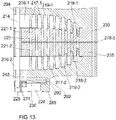
Figure 13 , the resiliently deformable displacer 218 may be an elongate resilient strip comprising a composite structure, laminate structure or assembly, secured to thehousing 212 between annular diaphragm mounts 235. The displacer 218 may comprise a first resilient coil 218-1, a second resilient coil 218-2 disposed opposite and spaced apart from the first resilient coil and a thermally insulating member 218-3 disposed intermediate and separating the first and second resilient coils. The resilient coils 218-1, 218-2 may be made of a metal such as aluminium, or an aluminium alloy. The thermally insulating member 218-3 should be capable of withstanding the operating temperatures within the displacer chamber 218 and is preferably an elastomer or polymer that is stable at relatively high temperatures. The thermally insulating member 218-3 may comprise a hard rubber or polyether ether ketone (PEEK). In use, the provision of a thermally insulating member 218-3 between the resilient coils 218-1, 218-2 may maintain a temperature gradient across the displacer 218 that is greater than is achievable with a conventional one-piece displacer piston so that the temperature of the resilient coil 218-1 disposed in the hot end 226-1 of thedisplacer compartment 226 stays at least relatively close to the temperature of the hot end 226-1 while the temperature of the resilient coil 228-2 disposed in the cold end 226-2 of the displacer compartment 218 stays at least relatively close to the temperature of the cold end 226-2. This may provide for more efficient heat transfer to the working fluid at the hot end 226-1 as for each cycle of the displacer 218, the resilient coil 218-1 should absorb less of the heat QIN input at thefirst housing portion 232. Similarly, the heat transfer from the working fluid at the cold end 226-2 may be enhanced as the resilient coil 218-2 may remain relatively cooler than a conventional one-piece displacer piston operating in similar working conditions - As in the previous example, the
displacer compartment 226 varies in diameter along its length. In particular, the hot end 226-1 increases in diameter towards the thermally insulating portion 236 and the cold end 226-2 decreases in diameter from the thermally insulating portion towards thediaphragm compartment 228. As best seen inFigure 13 , the first andhousing portions displacer compartment 226 at the hot and cold ends 226-1, 226-2 of the compartment. The projections 227-1, 227-2 may define respective convoluted passages 229-1, 229-2 into which the displacer 218 moves as it reciprocates between the hot and cold ends 226-1, 226-2 of thedisplacer compartment 226. The projections 227-1, 227-2 may comprising spiralling walls. The resilient coil 218-1 may at least substantially fill the passage 219-1 when the displacer is at the hot end 226-1 of the displacer compartment and the resilient coil 218-2 may at least substantially fill the passage 219-2 when the displacer is at the cold end 226-2. The projections 227-1, 227-2 provide additional surface area for heat transfer at the hot and cold ends 226-1. 226-2 of thedisplacer compartment 226, which may improve the efficiency of the respective heat transfer processes. Although not shown in the illustrated example, the or each projection 227-1 or the or each projection 227-2 may be hollow to allow the feed of a heating or cooling fluid through the projections as described above in connection withFigure 11 . - The resilient coils 218-1, 218-2 define respective spiralling channels 221-1, 221-2 that are connected via a
spiralling channel 223 provided in the thermally insulating member 236. The spiralling channels 221-1, 221-2, 221-3 define a through-passage in the displacer 218 that allows working fluid to pass through the displacer to move between the hot and cold ends 226-1, 226-2 of thedisplacer compartment 226 as the displacer moves between the hot and cold ends. The spiralling channels 221-1, 221-2 may be configured to mate with the projections 227-1, 227-1. - In some examples, it may be desirable to pressurise the displacer compartment prior to running the closed cycle regenerative heat engine so that the initial pressure is above atmospheric. For example, the displacer compartment may be pressurised to 2 atmospheres (approximately 200kPa). In examples in which the displacer compartment is pre-pressurised, it is desirable to ensure that the pressure on either side of the piston, or diaphragm, is balanced.
Figures 12 and13 show a pressurisation system configured to allow pre-pressurisation of thedisplacer compartment 226. Referring toFigure 12 , avalve 286 is provided in awall 288 of thehousing 212 that partially defines thediaphragm compartment 228. Thevalve 286 may be a one-way valve or, for example, a Schrader valve. Referring toFigure 13 , one ormore bypass passages 290 may be provided to bypass thediaphragm 230 and allow working fluid to be pumped into thediaphragm compartment 226 via thevalve 286 anddiaphragm compartment 228. The or eachbypass passage 290 may take any convenient form according to the particular configuration of the engine housing. In the illustrated example, abypass passage 290 is shown comprising a through-hole in anannular housing member 292 disposed between thewall 288 and thesecond housing portion 234, a recess in an end of thewall 288 that is in flow communication with the upstream end of the through-hole and a recess in thesecond housing portion 234 that is in flow communication with the downstream end of the through-hole. - The operation of the closed cycle
regenerative heat engine 210 is analogous to the operation of the closed cycleregenerative heat engine 10 as illustrated byFigures 4 to 9 and so will not be described in detail again. In similar fashion to thedisplacer 18 of the closed cycleregenerative heat engine 10, the displacer 218 of the closed cycleregenerative heat engine 210 fills the hot and cold ends 226-1, 226-2 when it reaches the respective ends of its reciprocating motion between the two ends. - In use, working fluid pumped in at the
valve 286 passes from thediaphragm compartment 228 to the cold end 226-2 of the displacer compartment via the connectingpassage 290 and twoopenings 242 that extend between the displacer compartment and the diaphragm compartment. From the cold end 226-2 of thedisplacer compartment 226, the pumped working fluid is able to flow to the hot end 226-1 of thedisplacer compartment 226 by passing through the spiralling channels 221-2, 221-2 andapertures 223 of the displacer 218. From the hot end 226-1, the pumped working fluid is able pass into thecompartment 284 that houses the linearelectrical actuator 246 via the clearance between theshaft 214 and abearing 294 that supports theshaft 214. Thus, thedisplacer compartment 216, thediaphragm compartment 228 on both sides of thediaphragm 230 and thecompartment 246 represent a closed system that can be pre-pressurised to a pressure above atmospheric that is substantially equal throughout the closed system so as not to adversely affect the operation of the moving parts of the engine in the chamber. - A closed cycle regenerative heat engine embodying one or more of the operating features described above has a resiliently deformable displacer that has a portion anchored and so cannot move and a portion that is connected with a reciprocating shaft. As the shaft reciprocates, the displacer deforms so as to move a working fluid between respective heating and cooling locations in a chamber. The shaft may be driven by a flywheel powered by the engine output or an electrical actuator. The shaft may reciprocate at or near the natural frequency of the resiliently deformable displacer. This may reduce the input energy needed to operate the displacer and so increase the efficiency of the engine. In some examples, a frequency adjuster may be provided to tune the natural frequency of the displacer to the engine drive speed.
- As the working fluid moves between the respective heating and cooling locations, it passes through the resiliently deformable displacer. As compared with a conventional one-piece piston displacer, this may significantly increase the surface area of the displacer available for heat exchange with the working fluid.
- In some examples, the displacer may comprise first and second members, or body parts, separated by thermal insulation. One of the first and second members is disposed on the side of the heating location and the other is disposed on the side of the cooling location. The effect of the thermally insulating layer may be to prevent, or at least significantly inhibit heat transfer between the first and second members. Thus, the member on the side of the heating location will be maintained at a relatively higher temperature than the member on the side of the cooling location. Accordingly, the first and second members will be maintained at a temperature the same as, or at least closer to, the temperature of the respective heating and cooling locations, thereby potentially increasing the efficiency of the heat transfer processes affecting the working fluid at the heating and cooling locations.
- In some examples, provision may be made for pre-pressurising the working fluid. This may provide for improved power output. A pressurisation system may be provided to allows pressurisation of the working fluid. The pressurisation system includes one or more passages or clearances between components to allow the pressurisation to affect all parts of the engine chamber in which moving parts associated with the displacer and power piston or diaphragm are housed so that the pressures acting on those parts are at last substantially balanced.
- In conventional Stirling engines, there is a significant clearance between the displacer piston and the walls of the cylinder. This is to allow the working fluid to pass around the displacer piston when moving between the heating and cooling locations. This means that when the displacer piston is at the respective ends of its reciprocating movement there is a dead space around the displacer piston containing a significant body of working fluid. This reduces the overall efficiency of the engine. In the illustrated examples of a closed cycle regenerative engine, the resiliently deformable displacer at least substantially fills the heating and cooling locations when at the ends of its reciprocating movement. In the example illustrated by
Figures 1 to 9 , the resiliently deformable displacer deforms so as to leave substantially no gap between the outer periphery of the displacer and the housing and the internal through-passage through which the working fluid passes as it moves between the heating and cooling locations is closed up. In similar fashion, in the examples shown inFigures 10 and11 and12 and13 , the resiliently deformable displacers leave substantially no gap between the outer periphery of the displacer and the housing and the internal through-passage through which the working fluid passes as it moves between the heating and cooling locations is blocked. Blockage of the internal through-passage may be partly due to deformation of the resiliently deformable displacer and partly due to the projections entering the internal through-passage. When the displacer is filling the heating and cooling locations, an outer periphery of the displacer may virtually, or actually, engage the housing so that there is no dead space surrounding the displacer. This may increase the efficiency of the closed cycle regenerative heat engine by ensuring that a larger volume of the working fluid is heated and cooled at the heating and cooling locations.
Claims (15)
- A closed cycle regenerative heat engine comprising:a housing (12; 112; 212) defining a chamber (14);a resiliently deformable displacer (18; 118; 218) housed in said chamber;a shaft (24; 124; 224) connected with said resiliently deformable displacer; anda movable member (30; 130; 230) housed in said chamber,wherein said resiliently deformable displacer (18; 118; 218) is secured to said housing (12; 112; 212) and is resiliently deformable in response to movement of said shaft (24; 124; 224) to displace a working fluid between respective heating and cooling locations in said chamber at which heat is input to said working fluid and said working fluid is cooled, and
said movable member (30; 130; 230) is in sealing engagement with said housing (12; 112; 212) and movable in response to pressure changes of said working fluid caused by said heating and cooling of said working fluid to provide a mechanical power,characterised in that said resiliently deformable displacer (18; 118; 218) comprises an elongate resilient strip that has a first end connected with said shaft (24; 124; 224), a second end connected with said housing (12; 112; 212) and winds about said shaft. - A closed cycle regenerative heat engine as claimed in claim 1, wherein said resiliently deformable displacer (18; 118; 218) is secured to a wall of said chamber.
- A closed cycle regenerative heat engine as claimed in claim 2, wherein said housing (12; 112; 212) comprises a first housing portion (32; 132; 232) at which, in use, heat is input to said chamber from an external source to heat said heating location, a second housing portion (34; 134; 234) at which, in use, heat is rejected from chamber to cool said cooling location and a thermally insulating portion (36; 136; 235) disposed intermediate said first and second housing portions.
- A closed cycle regenerative heat engine as claimed as claimed in claim 3, wherein said wall to which said resiliently deformable displacer (18; 118; 218) is secured is defined by said thermally insulating portion (36; 136; 235).
- A closed cycle regenerative heat engine as claimed in any one of the preceding claims, wherein said chamber comprises a first compartment (26; 126; 226) that houses said displacer (18; 118; 218), said first compartment has a first end (26-1, 126-1, 226-1), a second end (26-2, 126-2, 226-2) and a width that increases from said first end towards an intermediate region and decreases from said intermediate region to said second end.
- A closed cycle regenerative heat engine as claimed in claim 5, wherein said resiliently deformable displacer (18; 118; 218) and said first and second ends are configured such that when, in use, said resiliently deformable displacer has displaced said working fluid to said cooling location said resiliently deformable displacer fills said first end (26-1, 126-1, 226-1) and when said resiliently deformable displacer has displaced said working fluid to said heating location said resiliently deformable displacer fills said second end (26-2, 126-2, 226-2).
- A closed cycle regenerative heat engine as claimed in claim 5 or 6, wherein said chamber defines a second compartment (28; 128; 228) that houses said movable member (30; 130; 230) and said first and second compartments are in fluid communication to permit said working fluid to act on said movable member.
- A closed cycle regenerative heat engine as claimed in any one of the preceding claims, wherein said resiliently deformable displacer (18; 118; 218) defines at least one through-passage configured so that, in use, working fluid displaced between said heating and cooling locations passes through said through-passage.
- A closed cycle regenerative heat engine as claimed in any one of the preceding claims, wherein said resiliently deformable displacer (18; 118; 218) deforms to reciprocate between said heating and cooling locations along a first axis (116) in said chamber and said movable member (30; 130; 230) reciprocates along a second axis (156) that is perpendicular to said first axis.
- A closed cycle regenerative heat engine as claimed in any one of the preceding claims, wherein said resiliently deformable displacer (218) comprises a first resilient member (218-1), a second resilient member (218-2) and a thermally insulating member (218-3) disposed intermediate said first and second resilient members to thermally insulate said first resilient member with respect to said second resilient member.
- A closed cycle regenerative heat engine as claimed in any one of the preceding claims, further comprising at least one projection (127-1, 127-2) extending into said chamber (126) at one of said respective locations, wherein said at least one projection defines a convoluted passage (129-1, 129-2) and said resiliently deformable displacer (118) is deformable to enter said convoluted passage when displacing said working fluid to the other of said respective locations.
- A closed cycle regenerative heat engine as claimed in claim 11, wherein at said at least one projection (127-1, 127-2) is hollow.
- A closed cycle regenerative heat engine as claimed in any one of the preceding claims, wherein said shaft (224) is connected with an electrical actuator (246) configured to drive said resiliently deformable displacer (216).
- A closed cycle regenerative heat engine as claimed in claim 13, wherein said electrical actuator is configured to drive said resiliently deformable displacer at a natural frequency of said resiliently deformable displacer.
- A closed cycle regenerative heat engine as claimed in any one of the preceding claims, wherein said movable member comprises a piston (30; 130) or a diaphragm (230).
Applications Claiming Priority (2)
| Application Number | Priority Date | Filing Date | Title |
|---|---|---|---|
| GBGB1609258.7A GB201609258D0 (en) | 2016-05-25 | 2016-05-25 | Closed cycle regenerative heat engines |
| PCT/GB2017/051498 WO2017203273A2 (en) | 2016-05-25 | 2017-05-25 | Closed cycle regenerative heat engines |
Publications (2)
| Publication Number | Publication Date |
|---|---|
| EP3464863A2 EP3464863A2 (en) | 2019-04-10 |
| EP3464863B1 true EP3464863B1 (en) | 2021-03-31 |
Family
ID=56369992
Family Applications (1)
| Application Number | Title | Priority Date | Filing Date |
|---|---|---|---|
| EP17732992.7A Active EP3464863B1 (en) | 2016-05-25 | 2017-05-25 | Closed cycle regenerative heat engines |
Country Status (5)
| Country | Link |
|---|---|
| US (1) | US10890138B2 (en) |
| EP (1) | EP3464863B1 (en) |
| ES (1) | ES2886454T3 (en) |
| GB (1) | GB201609258D0 (en) |
| WO (1) | WO2017203273A2 (en) |
Families Citing this family (2)
| Publication number | Priority date | Publication date | Assignee | Title |
|---|---|---|---|---|
| GB201715415D0 (en) * | 2017-09-22 | 2017-11-08 | Stirling Works Global Ltd | Closed cycle regenerative heat |
| GB201917210D0 (en) * | 2019-11-26 | 2020-01-08 | Stirling Works Global Ltd | Closed cycle regenerative heat engines |
Family Cites Families (8)
| Publication number | Priority date | Publication date | Assignee | Title |
|---|---|---|---|---|
| GB1252258A (en) | 1968-01-19 | 1971-11-03 | ||
| GB1397548A (en) * | 1971-08-02 | 1975-06-11 | Atomic Energy Authority Uk | Stirling cycle heat engines |
| JPS5537540A (en) | 1978-09-09 | 1980-03-15 | Naoji Isshiki | Airtight stirling engine |
| US4801308A (en) * | 1983-10-03 | 1989-01-31 | Keefer Bowie | Apparatus and process for pressure swing adsorption separation |
| JPH055479A (en) | 1991-06-27 | 1993-01-14 | Nok Corp | Stirling engine |
| DE4442505A1 (en) | 1994-11-30 | 1996-06-05 | Peter Dipl Ing Maeckel | System for increasing heat transmission of fluids in variable volumes |
| JP2001090607A (en) | 1999-09-21 | 2001-04-03 | Masamitsu Nakano | Stirling engine |
| JP2008261520A (en) * | 2007-04-10 | 2008-10-30 | Sharp Corp | Stirling engine and equipment installed in Stirling engine |
-
2016
- 2016-05-25 GB GBGB1609258.7A patent/GB201609258D0/en not_active Ceased
-
2017
- 2017-05-25 EP EP17732992.7A patent/EP3464863B1/en active Active
- 2017-05-25 US US16/304,402 patent/US10890138B2/en active Active
- 2017-05-25 ES ES17732992T patent/ES2886454T3/en active Active
- 2017-05-25 WO PCT/GB2017/051498 patent/WO2017203273A2/en not_active Ceased
Non-Patent Citations (1)
| Title |
|---|
| None * |
Also Published As
| Publication number | Publication date |
|---|---|
| WO2017203273A2 (en) | 2017-11-30 |
| US20200088131A1 (en) | 2020-03-19 |
| GB201609258D0 (en) | 2016-07-06 |
| US10890138B2 (en) | 2021-01-12 |
| WO2017203273A3 (en) | 2018-01-04 |
| ES2886454T3 (en) | 2021-12-20 |
| EP3464863A2 (en) | 2019-04-10 |
Similar Documents
| Publication | Publication Date | Title |
|---|---|---|
| US9234480B2 (en) | Isothermal machines, systems and methods | |
| US5642618A (en) | Combination gas and flexure spring construction for free piston devices | |
| US7076941B1 (en) | Externally heated engine | |
| CN112576404A (en) | Free piston and cylinder assembly and stirling engine | |
| US11530668B2 (en) | Closed cycle regenerative heat engines | |
| US6701708B2 (en) | Moveable regenerator for stirling engines | |
| US8590301B2 (en) | Free-piston stirling machine for extreme temperatures | |
| KR100862965B1 (en) | Heat engine | |
| JP2009236456A (en) | Pulse tube-type heat storage engine | |
| US10890138B2 (en) | Closed cycle regenerative heat engines | |
| WO2006070832A1 (en) | Piston device, stirling engine, and external combustion engine | |
| CN122029347A (en) | Single-cylinder internal heating type heat engine | |
| CN104481726A (en) | Three-piston type free-piston stirling engine | |
| US10774783B2 (en) | Liquid piston stirling engine with linear generator | |
| JP2004138064A (en) | Two-cycle Stirling engine having two movable members | |
| GB2594543A (en) | Closed cycle regenerative heat engines | |
| CN114688755B (en) | Thermally driven Stirling refrigeration system | |
| US5109673A (en) | Relative gas spring configuration free-piston stirling cycle system | |
| US7607299B2 (en) | Thermal cycle engine with augmented thermal energy input area | |
| US20180087473A1 (en) | Double-acting free-piston-stirling cycle machine with linear generator | |
| JP3806730B2 (en) | Free piston type Stirling engine | |
| NL2024832B1 (en) | Energy transfer apparatus and associated methods | |
| JPH07269969A (en) | Wilmier heat pump | |
| KR101116715B1 (en) | Heat engine | |
| KR20260029252A (en) | Hot-gas free-piston stirling engine with efficient hot air inlet |
Legal Events
| Date | Code | Title | Description |
|---|---|---|---|
| STAA | Information on the status of an ep patent application or granted ep patent |
Free format text: STATUS: UNKNOWN |
|
| STAA | Information on the status of an ep patent application or granted ep patent |
Free format text: STATUS: THE INTERNATIONAL PUBLICATION HAS BEEN MADE |
|
| PUAI | Public reference made under article 153(3) epc to a published international application that has entered the european phase |
Free format text: ORIGINAL CODE: 0009012 |
|
| STAA | Information on the status of an ep patent application or granted ep patent |
Free format text: STATUS: REQUEST FOR EXAMINATION WAS MADE |
|
| 17P | Request for examination filed |
Effective date: 20190102 |
|
| AK | Designated contracting states |
Kind code of ref document: A2 Designated state(s): AL AT BE BG CH CY CZ DE DK EE ES FI FR GB GR HR HU IE IS IT LI LT LU LV MC MK MT NL NO PL PT RO RS SE SI SK SM TR |
|
| AX | Request for extension of the european patent |
Extension state: BA ME |
|
| DAV | Request for validation of the european patent (deleted) | ||
| DAX | Request for extension of the european patent (deleted) | ||
| GRAP | Despatch of communication of intention to grant a patent |
Free format text: ORIGINAL CODE: EPIDOSNIGR1 |
|
| STAA | Information on the status of an ep patent application or granted ep patent |
Free format text: STATUS: GRANT OF PATENT IS INTENDED |
|
| INTG | Intention to grant announced |
Effective date: 20200527 |
|
| GRAA | (expected) grant |
Free format text: ORIGINAL CODE: 0009210 |
|
| GRAS | Grant fee paid |
Free format text: ORIGINAL CODE: EPIDOSNIGR3 |
|
| STAA | Information on the status of an ep patent application or granted ep patent |
Free format text: STATUS: THE PATENT HAS BEEN GRANTED |
|
| AK | Designated contracting states |
Kind code of ref document: B1 Designated state(s): AL AT BE BG CH CY CZ DE DK EE ES FI FR GB GR HR HU IE IS IT LI LT LU LV MC MK MT NL NO PL PT RO RS SE SI SK SM TR |
|
| REG | Reference to a national code |
Ref country code: GB Ref legal event code: FG4D Ref country code: CH Ref legal event code: EP |
|
| REG | Reference to a national code |
Ref country code: DE Ref legal event code: R096 Ref document number: 602017035667 Country of ref document: DE Ref country code: AT Ref legal event code: REF Ref document number: 1377204 Country of ref document: AT Kind code of ref document: T Effective date: 20210415 |
|
| REG | Reference to a national code |
Ref country code: IE Ref legal event code: FG4D |
|
| REG | Reference to a national code |
Ref country code: LT Ref legal event code: MG9D |
|
| PG25 | Lapsed in a contracting state [announced via postgrant information from national office to epo] |
Ref country code: BG Free format text: LAPSE BECAUSE OF FAILURE TO SUBMIT A TRANSLATION OF THE DESCRIPTION OR TO PAY THE FEE WITHIN THE PRESCRIBED TIME-LIMIT Effective date: 20210630 Ref country code: NO Free format text: LAPSE BECAUSE OF FAILURE TO SUBMIT A TRANSLATION OF THE DESCRIPTION OR TO PAY THE FEE WITHIN THE PRESCRIBED TIME-LIMIT Effective date: 20210630 Ref country code: FI Free format text: LAPSE BECAUSE OF FAILURE TO SUBMIT A TRANSLATION OF THE DESCRIPTION OR TO PAY THE FEE WITHIN THE PRESCRIBED TIME-LIMIT Effective date: 20210331 Ref country code: HR Free format text: LAPSE BECAUSE OF FAILURE TO SUBMIT A TRANSLATION OF THE DESCRIPTION OR TO PAY THE FEE WITHIN THE PRESCRIBED TIME-LIMIT Effective date: 20210331 |
|
| PG25 | Lapsed in a contracting state [announced via postgrant information from national office to epo] |
Ref country code: RS Free format text: LAPSE BECAUSE OF FAILURE TO SUBMIT A TRANSLATION OF THE DESCRIPTION OR TO PAY THE FEE WITHIN THE PRESCRIBED TIME-LIMIT Effective date: 20210331 Ref country code: LV Free format text: LAPSE BECAUSE OF FAILURE TO SUBMIT A TRANSLATION OF THE DESCRIPTION OR TO PAY THE FEE WITHIN THE PRESCRIBED TIME-LIMIT Effective date: 20210331 Ref country code: SE Free format text: LAPSE BECAUSE OF FAILURE TO SUBMIT A TRANSLATION OF THE DESCRIPTION OR TO PAY THE FEE WITHIN THE PRESCRIBED TIME-LIMIT Effective date: 20210331 |
|
| REG | Reference to a national code |
Ref country code: NL Ref legal event code: MP Effective date: 20210331 |
|
| REG | Reference to a national code |
Ref country code: AT Ref legal event code: MK05 Ref document number: 1377204 Country of ref document: AT Kind code of ref document: T Effective date: 20210331 |
|
| PG25 | Lapsed in a contracting state [announced via postgrant information from national office to epo] |
Ref country code: LT Free format text: LAPSE BECAUSE OF FAILURE TO SUBMIT A TRANSLATION OF THE DESCRIPTION OR TO PAY THE FEE WITHIN THE PRESCRIBED TIME-LIMIT Effective date: 20210331 Ref country code: CZ Free format text: LAPSE BECAUSE OF FAILURE TO SUBMIT A TRANSLATION OF THE DESCRIPTION OR TO PAY THE FEE WITHIN THE PRESCRIBED TIME-LIMIT Effective date: 20210331 Ref country code: EE Free format text: LAPSE BECAUSE OF FAILURE TO SUBMIT A TRANSLATION OF THE DESCRIPTION OR TO PAY THE FEE WITHIN THE PRESCRIBED TIME-LIMIT Effective date: 20210331 Ref country code: NL Free format text: LAPSE BECAUSE OF FAILURE TO SUBMIT A TRANSLATION OF THE DESCRIPTION OR TO PAY THE FEE WITHIN THE PRESCRIBED TIME-LIMIT Effective date: 20210331 Ref country code: SM Free format text: LAPSE BECAUSE OF FAILURE TO SUBMIT A TRANSLATION OF THE DESCRIPTION OR TO PAY THE FEE WITHIN THE PRESCRIBED TIME-LIMIT Effective date: 20210331 Ref country code: AT Free format text: LAPSE BECAUSE OF FAILURE TO SUBMIT A TRANSLATION OF THE DESCRIPTION OR TO PAY THE FEE WITHIN THE PRESCRIBED TIME-LIMIT Effective date: 20210331 |
|
| PG25 | Lapsed in a contracting state [announced via postgrant information from national office to epo] |
Ref country code: IS Free format text: LAPSE BECAUSE OF FAILURE TO SUBMIT A TRANSLATION OF THE DESCRIPTION OR TO PAY THE FEE WITHIN THE PRESCRIBED TIME-LIMIT Effective date: 20210731 Ref country code: PT Free format text: LAPSE BECAUSE OF FAILURE TO SUBMIT A TRANSLATION OF THE DESCRIPTION OR TO PAY THE FEE WITHIN THE PRESCRIBED TIME-LIMIT Effective date: 20210802 Ref country code: PL Free format text: LAPSE BECAUSE OF FAILURE TO SUBMIT A TRANSLATION OF THE DESCRIPTION OR TO PAY THE FEE WITHIN THE PRESCRIBED TIME-LIMIT Effective date: 20210331 Ref country code: RO Free format text: LAPSE BECAUSE OF FAILURE TO SUBMIT A TRANSLATION OF THE DESCRIPTION OR TO PAY THE FEE WITHIN THE PRESCRIBED TIME-LIMIT Effective date: 20210331 Ref country code: SK Free format text: LAPSE BECAUSE OF FAILURE TO SUBMIT A TRANSLATION OF THE DESCRIPTION OR TO PAY THE FEE WITHIN THE PRESCRIBED TIME-LIMIT Effective date: 20210331 |
|
| REG | Reference to a national code |
Ref country code: ES Ref legal event code: FG2A Ref document number: 2886454 Country of ref document: ES Kind code of ref document: T3 Effective date: 20211220 |
|
| REG | Reference to a national code |
Ref country code: CH Ref legal event code: PL |
|
| REG | Reference to a national code |
Ref country code: DE Ref legal event code: R097 Ref document number: 602017035667 Country of ref document: DE |
|
| PG25 | Lapsed in a contracting state [announced via postgrant information from national office to epo] |
Ref country code: AL Free format text: LAPSE BECAUSE OF FAILURE TO SUBMIT A TRANSLATION OF THE DESCRIPTION OR TO PAY THE FEE WITHIN THE PRESCRIBED TIME-LIMIT Effective date: 20210331 Ref country code: CH Free format text: LAPSE BECAUSE OF NON-PAYMENT OF DUE FEES Effective date: 20210531 Ref country code: DK Free format text: LAPSE BECAUSE OF FAILURE TO SUBMIT A TRANSLATION OF THE DESCRIPTION OR TO PAY THE FEE WITHIN THE PRESCRIBED TIME-LIMIT Effective date: 20210331 Ref country code: MC Free format text: LAPSE BECAUSE OF FAILURE TO SUBMIT A TRANSLATION OF THE DESCRIPTION OR TO PAY THE FEE WITHIN THE PRESCRIBED TIME-LIMIT Effective date: 20210331 Ref country code: LI Free format text: LAPSE BECAUSE OF NON-PAYMENT OF DUE FEES Effective date: 20210531 Ref country code: LU Free format text: LAPSE BECAUSE OF NON-PAYMENT OF DUE FEES Effective date: 20210525 |
|
| PLBE | No opposition filed within time limit |
Free format text: ORIGINAL CODE: 0009261 |
|
| STAA | Information on the status of an ep patent application or granted ep patent |
Free format text: STATUS: NO OPPOSITION FILED WITHIN TIME LIMIT |
|
| REG | Reference to a national code |
Ref country code: BE Ref legal event code: MM Effective date: 20210531 |
|
| 26N | No opposition filed |
Effective date: 20220104 |
|
| PG25 | Lapsed in a contracting state [announced via postgrant information from national office to epo] |
Ref country code: IE Free format text: LAPSE BECAUSE OF NON-PAYMENT OF DUE FEES Effective date: 20210525 |
|
| PG25 | Lapsed in a contracting state [announced via postgrant information from national office to epo] |
Ref country code: IS Free format text: LAPSE BECAUSE OF FAILURE TO SUBMIT A TRANSLATION OF THE DESCRIPTION OR TO PAY THE FEE WITHIN THE PRESCRIBED TIME-LIMIT Effective date: 20210731 |
|
| PG25 | Lapsed in a contracting state [announced via postgrant information from national office to epo] |
Ref country code: IT Free format text: LAPSE BECAUSE OF FAILURE TO SUBMIT A TRANSLATION OF THE DESCRIPTION OR TO PAY THE FEE WITHIN THE PRESCRIBED TIME-LIMIT Effective date: 20210331 Ref country code: BE Free format text: LAPSE BECAUSE OF NON-PAYMENT OF DUE FEES Effective date: 20210531 |
|
| PG25 | Lapsed in a contracting state [announced via postgrant information from national office to epo] |
Ref country code: CY Free format text: LAPSE BECAUSE OF FAILURE TO SUBMIT A TRANSLATION OF THE DESCRIPTION OR TO PAY THE FEE WITHIN THE PRESCRIBED TIME-LIMIT Effective date: 20210331 |
|
| PG25 | Lapsed in a contracting state [announced via postgrant information from national office to epo] |
Ref country code: HU Free format text: LAPSE BECAUSE OF FAILURE TO SUBMIT A TRANSLATION OF THE DESCRIPTION OR TO PAY THE FEE WITHIN THE PRESCRIBED TIME-LIMIT; INVALID AB INITIO Effective date: 20170525 Ref country code: GR Free format text: LAPSE BECAUSE OF FAILURE TO SUBMIT A TRANSLATION OF THE DESCRIPTION OR TO PAY THE FEE WITHIN THE PRESCRIBED TIME-LIMIT Effective date: 20210331 |
|
| PGFP | Annual fee paid to national office [announced via postgrant information from national office to epo] |
Ref country code: ES Payment date: 20230531 Year of fee payment: 6 |
|
| PG25 | Lapsed in a contracting state [announced via postgrant information from national office to epo] |
Ref country code: MK Free format text: LAPSE BECAUSE OF FAILURE TO SUBMIT A TRANSLATION OF THE DESCRIPTION OR TO PAY THE FEE WITHIN THE PRESCRIBED TIME-LIMIT Effective date: 20210331 |
|
| PG25 | Lapsed in a contracting state [announced via postgrant information from national office to epo] |
Ref country code: TR Free format text: LAPSE BECAUSE OF FAILURE TO SUBMIT A TRANSLATION OF THE DESCRIPTION OR TO PAY THE FEE WITHIN THE PRESCRIBED TIME-LIMIT Effective date: 20210331 |
|
| REG | Reference to a national code |
Ref country code: ES Ref legal event code: FD2A Effective date: 20240702 |
|
| PG25 | Lapsed in a contracting state [announced via postgrant information from national office to epo] |
Ref country code: ES Free format text: LAPSE BECAUSE OF NON-PAYMENT OF DUE FEES Effective date: 20230526 |
|
| PG25 | Lapsed in a contracting state [announced via postgrant information from national office to epo] |
Ref country code: ES Free format text: LAPSE BECAUSE OF NON-PAYMENT OF DUE FEES Effective date: 20230526 |
|
| PG25 | Lapsed in a contracting state [announced via postgrant information from national office to epo] |
Ref country code: MT Free format text: LAPSE BECAUSE OF FAILURE TO SUBMIT A TRANSLATION OF THE DESCRIPTION OR TO PAY THE FEE WITHIN THE PRESCRIBED TIME-LIMIT Effective date: 20210331 |
|
| PGFP | Annual fee paid to national office [announced via postgrant information from national office to epo] |
Ref country code: GB Payment date: 20250630 Year of fee payment: 9 |
|
| PGFP | Annual fee paid to national office [announced via postgrant information from national office to epo] |
Ref country code: FR Payment date: 20250602 Year of fee payment: 9 |
|
| PGFP | Annual fee paid to national office [announced via postgrant information from national office to epo] |
Ref country code: DE Payment date: 20251111 Year of fee payment: 9 |