EP3463889B1 - Apparatus for actuating a hydraulic carrier rod of a rotary printing machine - Google Patents
Apparatus for actuating a hydraulic carrier rod of a rotary printing machine Download PDFInfo
- Publication number
- EP3463889B1 EP3463889B1 EP17727490.9A EP17727490A EP3463889B1 EP 3463889 B1 EP3463889 B1 EP 3463889B1 EP 17727490 A EP17727490 A EP 17727490A EP 3463889 B1 EP3463889 B1 EP 3463889B1
- Authority
- EP
- European Patent Office
- Prior art keywords
- carrier rod
- tool
- hydraulic
- actuating member
- rotary drive
- Prior art date
- Legal status (The legal status is an assumption and is not a legal conclusion. Google has not performed a legal analysis and makes no representation as to the accuracy of the status listed.)
- Active
Links
Images


Classifications
-
- B—PERFORMING OPERATIONS; TRANSPORTING
- B41—PRINTING; LINING MACHINES; TYPEWRITERS; STAMPS
- B41F—PRINTING MACHINES OR PRESSES
- B41F27/00—Devices for attaching printing elements or formes to supports
- B41F27/10—Devices for attaching printing elements or formes to supports for attaching non-deformable curved printing formes to forme cylinders
- B41F27/105—Devices for attaching printing elements or formes to supports for attaching non-deformable curved printing formes to forme cylinders for attaching cylindrical printing formes
-
- B—PERFORMING OPERATIONS; TRANSPORTING
- B41—PRINTING; LINING MACHINES; TYPEWRITERS; STAMPS
- B41F—PRINTING MACHINES OR PRESSES
- B41F30/00—Devices for attaching coverings or make-ready devices; Guiding devices for coverings
- B41F30/04—Devices for attaching coverings or make-ready devices; Guiding devices for coverings attaching to transfer cylinders
-
- B—PERFORMING OPERATIONS; TRANSPORTING
- B41—PRINTING; LINING MACHINES; TYPEWRITERS; STAMPS
- B41P—INDEXING SCHEME RELATING TO PRINTING, LINING MACHINES, TYPEWRITERS, AND TO STAMPS
- B41P2227/00—Mounting or handling printing plates; Forming printing surfaces in situ
- B41P2227/20—Means enabling or facilitating exchange of tubular printing or impression members, e.g. printing sleeves, blankets
- B41P2227/21—Means facilitating exchange of sleeves mounted on cylinders without removing the cylinder from the press
Definitions
- the invention relates to a device for actuating a hydraulic carrier rod of a rotary printing machine, which has a rotary drive for the carrier rod, an electronic control device for the rotary drive, and a removable bearing arrangement for supporting one end of the carrier rod, and wherein the carrier rod has a hydraulic clamping system for clamping a cylinder sleeve on the carrier rod and the clamping system has a rotatable actuating member with a coupling for a tool at the end of the carrier rod that is supported in the removable bearing arrangement.
- Rotary printing machines are known, for example, from EP 1 362 697 B1 , in which exchangeable cylindrical sleeves such as printing cylinder sleeves are pushed onto a carrier rod that is supported in a rotationally driven manner in the frame of the printing machine such that it remains permanently in the frame.
- the carrier rod has a hydraulic clamping system with which parts of the circumferential wall of the carrier rod can be expanded by hydraulic pressure so that the cylinder sleeve is held clamped on the carrier rod.
- the hydraulic pressure is relieved and the bearing arrangement is removed at one end of the carrier rod, the cylindrical sleeve can then be pulled off axially from the carrier rod.
- a rotatable actuating member is provided at the end of the carrier rod. By rotating this actuating member in one direction, the hydraulic fluid is pressurized, and by rotating in the opposite direction the pressure is relieved.
- the actuating member has a coupling for a tool. This coupling has, for example, the shape of an inner hexagon into which a hexagonal wrench can be inserted.
- the clamping system is operated by manually rotating the actuating member with the help of the tool.
- EP 1 745 929 A1 shows a further example of a rotary printing machine with a hydraulic carrier rod and exchangeable printing cylinder sleeves.
- the object of the invention is to provide a device that makes it possible to simplify and largely automate the actuation of the clamping system.
- the tool is thus held rotationally rigidly on the bearing arrangement so that the tool is always at hand at anytime.
- the tool is moved axially in the direction of the actuating member so that it engages with its coupling.
- the carrier rod is rotated with the fixed tool instead of rotating the tool.
- the already provided rotary drive is used.
- the extension movement of the tool holder and the rotation of the carrier rod are controlled by the electronic control device so that the work sequences are largely automatic.
- the control device s designed such that it can also measure the torque exerted by the rotary drive on the carrier rod.
- this function also allows counter torque to be measured, which the actuating member held by the tool exerts on the carrier rod. This makes it possible to dose precisely the actuating force exerted on the actuating member and thus the pressure in the hydraulic system.
- the angle of rotation by which the carrier rod is rotated, by means of the rotary drive can also be measured. This makes it possible, for example, to return the actuating member to a precisely defined starting position when the clamping system is relieved.
- an exemplary embodiment is explained in more detail with reference to the drawing.
- FIG. 1 two side parts 10, 12 of a frame of a rotary printing machine are shown in a partial section.
- the right side part 12 carries a bearing block 14 in which a carrier rod 16 is supported in such a way that it protrudes like a cantilever towards the opposite side part 10.
- a rotary drive 18 is arranged, on the outside of the bearing block 14, by means of which the carrier rod 16 can be rotated.
- the carrier rod 16 holds a cylinder sleeve 20 that is braced on the carrier rod by means of a hydraulic clamping system 22 and thus it can also be rotated by means of the rotary drive 18.
- a bearing block 24 is arranged which has a removal opening 26 that is dimensioned such that it allows the passage of the cylinder sleeve 20.
- a removable bearing arrangement 28 is held on the bearing block 24.
- This bearing arrangement 28 has a base plate 30 that, in the state shown in Fig. 1 , closes the removal opening 26 and on the inside it holds a bearing 32 for the respective end of the carrier rod 16.
- a drive unit 34 allows the bearing arrangement 28 to be pulled off axially from the bearing block 24 and to pivot it about a pivoting axis A into a position in which it opens the removal opening 26 so that the cylinder sleeve 20 can be pulled off the carrier rod 16 after the hydraulic clamping system 22 has been deactivated.
- an actuating member 36 is arranged at the end of the carrier rod 16 accommodated in the bearing 32, which can be rotated relative to the carrier rod 16 in order to pressurize the hydraulic fluid in the hydraulic clamping system 22.
- the actuating member 36 On the face side that faces the base plate 30 of the bearing arrangement 28, the actuating member 36 has a coupling 38, for example, in the form of an inner hexagon, for a tool 40.
- the tool 40 which has an outer hexagon complementary to the coupling 38, is held axially movably and rotationally rigidly on the base plate 30 by means of a tool holder 42.
- Fig. 1 the tool holder 42 is shown in a position in which it holds the tool 40 remotely in a position from the coupling 38.
- the unit formed by the carrier rod 16 and the cylinder sleeve 20 can thus be set in rotation by means of the rotary drive 18.
- FIG. 2 the end of the carrier rod 16, on which the actuating member is located, is shown in a magnified axial section.
- the hydraulic clamping system 22 is formed by a plurality of hydraulic bushes 44 that support a circumferential wall 46 of the carrier rod from within.
- Each hydraulic bushing has an annular chamber 48 within its outer circumferential wall and that is connected to a pressure chamber 52 filled with hydraulic fluid via a hydraulic line 50.
- the pressure chamber 52 is formed in the plug 54 inserted into the end of the carrier rod 16, which also accommodates the actuating member 36.
- the actuating member 36 has the form of a screw done into the plug 54 and at the same time forms a piston that limits the pressure chamber 52.
- Fig. 3 the bearing arrangement 28 is shown in a magnified scale.
- the tool holder 42 has a pneumatic cylinder 56 that is centred in the state shown in Fig. 1 and 3 on the axis of the carrier rod 16 and it can be axially extended, by means of the tool 40, so that its outer hexagon engages with the coupling of the actuating member 36, as shown in Fig. 3 .
- the hydraulic clamping system 22 must first be relieved.
- the carrier rod 16 and the cylinder sleeve 20 are rotated with the help of the rotary drive 18 such that the actuating member 36, which is held rotationally rigidly by the tool 40, is screwed out of the plug 54 so that the volume of the pressure chamber 52 increases and the hydraulic pressure decreases accordingly.
- the tool 40 is then pulled back, by means of the pneumatic cylinder 56, into the disengaged position.
- the entire bearing arrangement 28 is moved axially away from the bearing block 24.
- the bearing 32 is pulled off from the end of the carrier rod 16.
- the bearing arrangement 28 is pivoted about the pivoting axis A into the position shown in Fig. 4 and 6 , by means of the drive unit 34, in which it releases the removal opening 26 so that the cylinder sleeve 20 can be removed.
- a new cylinder sleeve can be mounted on the carrier rod 16. If the bearing arrangement 28 is pivoted back into the position shown in Fig. 3 and 5 , the bearing 32 and also the tool 40 will again be centred on the axis of the carrier rod, and thus on the coupling 38 of the actuating element 36.
- FIG. 1 an electronic control device 58 of the printing machine is shown schematically. This control device also controls, inter alia, the function of the rotary drive 18 as well as the function of the pneumatic cylinder 56 of the tool holder so that the above-described movement sequences can be coordinated and controlled by the control device 58.
- the rotary drive 18 usually contains an integrated angle incremental encoder, with which the angular position of the carrier rod can be measured. The angular position is fed back to the control device 58. In this way, it can be ensured that the actuating member 36 is always rotated by the same angle, so that the hydraulic pressure in the clamping system 22 can be maintained at the predetermined value with high precision.
- the control device 58 is also able to measure the torque actually exerted by the rotary drive in a known manner, for example, by means of the current consumption of the rotary drive 18.
- the control device can also operate in such a way that, upon tensioning of the clamping system, the rotary movement terminates as soon as the torque has reached a certain threshold value.
- the unscrewing movement of the actuating member 36 is also limited by a stop (not shown here), the unscrewing movement can be terminated as soon as the torque reaches a certain threshold value even when the clamping system is released. Otherwise, it is ensured based on the data from the angle incremental encoder that the actuating member 36 is brought into a defined neutral position when the clamping system is released.
Landscapes
- Rotary Presses (AREA)
- Supply, Installation And Extraction Of Printed Sheets Or Plates (AREA)
Description
- The invention relates to a device for actuating a hydraulic carrier rod of a rotary printing machine, which has a rotary drive for the carrier rod, an electronic control device for the rotary drive, and a removable bearing arrangement for supporting one end of the carrier rod, and wherein the carrier rod has a hydraulic clamping system for clamping a cylinder sleeve on the carrier rod and the clamping system has a rotatable actuating member with a coupling for a tool at the end of the carrier rod that is supported in the removable bearing arrangement.
- Rotary printing machines are known, for example, from
EP 1 362 697 B1 - To activate and deactivate the hydraulic clamping system, a rotatable actuating member is provided at the end of the carrier rod. By rotating this actuating member in one direction, the hydraulic fluid is pressurized, and by rotating in the opposite direction the pressure is relieved. The actuating member has a coupling for a tool. This coupling has, for example, the shape of an inner hexagon into which a hexagonal wrench can be inserted.
- In conventional printing machines, the clamping system is operated by manually rotating the actuating member with the help of the tool.
-
EP 1 745 929 A1 - The object of the invention is to provide a device that makes it possible to simplify and largely automate the actuation of the clamping system.
- This object is achieved by the apparatus according to
claim 1. - In the case of the apparatus according to the invention, the tool is thus held rotationally rigidly on the bearing arrangement so that the tool is always at hand at anytime. In order to couple the tool to the actuating member, the tool is moved axially in the direction of the actuating member so that it engages with its coupling. According to the invention, the carrier rod is rotated with the fixed tool instead of rotating the tool. For this purpose, the already provided rotary drive is used. The extension movement of the tool holder and the rotation of the carrier rod are controlled by the electronic control device so that the work sequences are largely automatic.
- The control device s designed such that it can also measure the torque exerted by the rotary drive on the carrier rod. When the clamping system is actuated, this function also allows counter torque to be measured, which the actuating member held by the tool exerts on the carrier rod. This makes it possible to dose precisely the actuating force exerted on the actuating member and thus the pressure in the hydraulic system.
- Alternatively or additionally, the angle of rotation by which the carrier rod is rotated, by means of the rotary drive, can also be measured. This makes it possible, for example, to return the actuating member to a precisely defined starting position when the clamping system is relieved. In the following, an exemplary embodiment is explained in more detail with reference to the drawing.
- Advantageous embodiments and further developments are specified in the subordinate claim.
- Shown are:
- Fig. 1
- a view of a cylinder sleeve that is mounted on a carrier rod and mounted in a rotatable manner in a printing machine;
- Fig. 2
- an axial section through one end of the carrier rod;
- Fig. 3
- a view of a bearing arrangement at one end of the carrier rod;
- Fig. 4
- a view of the bearing arrangement in a position in which the cylinder sleeve can be pulled off from the carrier rod;
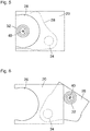
- Fig. 5
- an inside view of the bearing arrangement in the state according to
Fig. 3 , from the direction of the arrows V-V inFig. 3 ; and - Fig. 6
- shows an inside view of the bearing arrangement in the state according to
Fig. 4 , from the direction of the arrows VI- VI inFig. 4 . - In
Fig. 1 twoside parts Fig. 1 , theright side part 12 carries abearing block 14 in which acarrier rod 16 is supported in such a way that it protrudes like a cantilever towards theopposite side part 10. Arotary drive 18 is arranged, on the outside of thebearing block 14, by means of which thecarrier rod 16 can be rotated. Thecarrier rod 16 holds acylinder sleeve 20 that is braced on the carrier rod by means of ahydraulic clamping system 22 and thus it can also be rotated by means of therotary drive 18. On theleft side part 10 inFig. 1 , abearing block 24 is arranged which has a removal opening 26 that is dimensioned such that it allows the passage of thecylinder sleeve 20. Aremovable bearing arrangement 28 is held on thebearing block 24. This bearingarrangement 28 has abase plate 30 that, in the state shown inFig. 1 , closes the removal opening 26 and on the inside it holds abearing 32 for the respective end of thecarrier rod 16. Adrive unit 34 allows thebearing arrangement 28 to be pulled off axially from thebearing block 24 and to pivot it about a pivoting axis A into a position in which it opens the removal opening 26 so that thecylinder sleeve 20 can be pulled off thecarrier rod 16 after thehydraulic clamping system 22 has been deactivated. - To activate and deactivate the hydraulic clamping system, an actuating
member 36 is arranged at the end of thecarrier rod 16 accommodated in thebearing 32, which can be rotated relative to thecarrier rod 16 in order to pressurize the hydraulic fluid in thehydraulic clamping system 22. On the face side that faces thebase plate 30 of thebearing arrangement 28, the actuatingmember 36 has acoupling 38, for example, in the form of an inner hexagon, for atool 40. Thetool 40, which has an outer hexagon complementary to thecoupling 38, is held axially movably and rotationally rigidly on thebase plate 30 by means of atool holder 42. - In
Fig. 1 , thetool holder 42 is shown in a position in which it holds thetool 40 remotely in a position from thecoupling 38. In this state, the unit formed by thecarrier rod 16 and thecylinder sleeve 20 can thus be set in rotation by means of therotary drive 18. - In
Fig. 2 , the end of thecarrier rod 16, on which the actuating member is located, is shown in a magnified axial section. Thehydraulic clamping system 22 is formed by a plurality ofhydraulic bushes 44 that support acircumferential wall 46 of the carrier rod from within. Each hydraulic bushing has anannular chamber 48 within its outer circumferential wall and that is connected to apressure chamber 52 filled with hydraulic fluid via ahydraulic line 50. Thepressure chamber 52 is formed in theplug 54 inserted into the end of thecarrier rod 16, which also accommodates the actuatingmember 36. The actuatingmember 36 has the form of a screw done into theplug 54 and at the same time forms a piston that limits thepressure chamber 52. When the actuatingmember 36 is screwed deeper into theplug 54 by means of thetool 40, the hydraulic fluid in thepressure chamber 52, thehydraulic line 50 and theannular chambers 48 is thus compressed. The result is that the hydraulic bushes and the zones of thecircumferential wall 46 of thecarrier rod 16 supported by them expand elastically. Thecircumferential wall 46 of the carrier rod is thereby firmly clamped against the inner circumferential surface of thecylinder sleeve 20. When the actuatingmember 36 is rotated in the counter-clockwise direction, the hydraulic fluid is relieved and thereby thecylinder sleeve 20 is released so that it can be pulled off a i ally from thecarrier rod 16. - In
Fig. 3 , thebearing arrangement 28 is shown in a magnified scale. Thetool holder 42 has apneumatic cylinder 56 that is centred in the state shown inFig. 1 and3 on the axis of thecarrier rod 16 and it can be axially extended, by means of thetool 40, so that its outer hexagon engages with the coupling of the actuatingmember 36, as shown inFig. 3 . - If now the
cylinder sleeve 20 is to be released from thecarrier rod 16, thehydraulic clamping system 22 must first be relieved. For this purpose, thecarrier rod 16 and thecylinder sleeve 20 are rotated with the help of therotary drive 18 such that the actuatingmember 36, which is held rotationally rigidly by thetool 40, is screwed out of theplug 54 so that the volume of thepressure chamber 52 increases and the hydraulic pressure decreases accordingly. Thetool 40 is then pulled back, by means of thepneumatic cylinder 56, into the disengaged position. - Subsequently, by means of the
drive unit 34, theentire bearing arrangement 28 is moved axially away from thebearing block 24. Thebearing 32 is pulled off from the end of thecarrier rod 16. Thereafter, the bearingarrangement 28 is pivoted about the pivoting axis A into the position shown inFig. 4 and6 , by means of thedrive unit 34, in which it releases theremoval opening 26 so that thecylinder sleeve 20 can be removed. - By reversing the movement sequences described above, a new cylinder sleeve can be mounted on the
carrier rod 16. If the bearingarrangement 28 is pivoted back into the position shown inFig. 3 and5 , thebearing 32 and also thetool 40 will again be centred on the axis of the carrier rod, and thus on thecoupling 38 of theactuating element 36. - When the tool is extended again in the direction of the actuating
member 36 by means of thepneumatic cylinder 56, it can happen that the outer hexagon of the tool and the inner hexagon of thecoupling 38 are rotated relative to one another so that the tool cannot engage immediately. However, when the carrier rod and thus also the actuatingmember 36 are then rotated with the help of therotary drive 18, then, as it is held under elastic bias by the pneumatic cylinder, thetool 40 automatically locks as soon as the correct angular position is reached. During further rotation of the carrier rod, the actuatingmember 36 is then screwed deeper and thus the hydraulic system is pressurised again. - In
Fig. 1 , anelectronic control device 58 of the printing machine is shown schematically. This control device also controls, inter alia, the function of therotary drive 18 as well as the function of thepneumatic cylinder 56 of the tool holder so that the above-described movement sequences can be coordinated and controlled by thecontrol device 58. - The
rotary drive 18 usually contains an integrated angle incremental encoder, with which the angular position of the carrier rod can be measured. The angular position is fed back to thecontrol device 58. In this way, it can be ensured that the actuatingmember 36 is always rotated by the same angle, so that the hydraulic pressure in theclamping system 22 can be maintained at the predetermined value with high precision. - The
control device 58 is also able to measure the torque actually exerted by the rotary drive in a known manner, for example, by means of the current consumption of therotary drive 18. In this case, the control device can also operate in such a way that, upon tensioning of the clamping system, the rotary movement terminates as soon as the torque has reached a certain threshold value. - As far as the unscrewing movement of the actuating
member 36 is also limited by a stop (not shown here), the unscrewing movement can be terminated as soon as the torque reaches a certain threshold value even when the clamping system is released. Otherwise, it is ensured based on the data from the angle incremental encoder that the actuatingmember 36 is brought into a defined neutral position when the clamping system is released.
Claims (2)
- A hydraulic carrier rod (16) of a rotary printing machine in combination with an apparatus for actuating said hydraulic carrier rod (16), the apparatus comprising a rotary drive (18) for the carrier rod, an electronic control device (58) for the rotary drive, and a removable bearing arrangement (28) for supporting one end of the carrier rod (16), wherein the carrier rod (16) has a hydraulic clamping system (22) for clamping a cylinder sleeve (20) pushed onto the carrier rod, and the clamping system has a rotatable actuating member at the end of the carrier rod, which is mounted in the removable bearing arrangement (28), wherein the rotatable actuating member (36) has a coupling (38) for a tool (40), wherein the apparatus comprises a tool holder (42) with which the tool (40) is held axially movably and rotationally rigidly on the bearing arrangement (28),
characterised in that the control device (58) is set up to control an axial extension movement of the tool holder (42) and thereby to engage the tool (40) with the coupling (38) and to activate the rotary drive (18) to thereby rotate the carrier rod (16) relatively to the tool (40),
wherein the control device (58) is set up to rotate the carrier rod (16) at a defined angle relative to that actuating member (36) held by the tool (40) when clamping and/or relieving the hydraulic clamping system (22), and/or
wherein the control device (58) is set up to monitor the torque generated by the rotary drive (18), and when clamping and/or relieving the hydraulic clamping system (22), to terminate the rotation of the carrier rod (16) as soon as the torque reaches a predetermined threshold value. - Apparatus according to claim 1, wherein the tool holder (42) comprises a pneumatic cylinder (56) for extending and retracting the tool (40).
Applications Claiming Priority (2)
| Application Number | Priority Date | Filing Date | Title |
|---|---|---|---|
| DE202016102779.9U DE202016102779U1 (en) | 2016-05-25 | 2016-05-25 | Device for actuating a hydraulic carrier bar of a rotary printing machine |
| PCT/EP2017/025146 WO2017202506A1 (en) | 2016-05-25 | 2017-05-24 | Apparatus for actuating a hydraulic carrier rod of a rotary printing machine |
Publications (2)
| Publication Number | Publication Date |
|---|---|
| EP3463889A1 EP3463889A1 (en) | 2019-04-10 |
| EP3463889B1 true EP3463889B1 (en) | 2020-09-23 |
Family
ID=58994882
Family Applications (1)
| Application Number | Title | Priority Date | Filing Date |
|---|---|---|---|
| EP17727490.9A Active EP3463889B1 (en) | 2016-05-25 | 2017-05-24 | Apparatus for actuating a hydraulic carrier rod of a rotary printing machine |
Country Status (7)
| Country | Link |
|---|---|
| US (1) | US11001052B2 (en) |
| EP (1) | EP3463889B1 (en) |
| JP (1) | JP6690058B2 (en) |
| CA (1) | CA3024377C (en) |
| DE (1) | DE202016102779U1 (en) |
| ES (1) | ES2828311T3 (en) |
| WO (1) | WO2017202506A1 (en) |
Family Cites Families (18)
| Publication number | Priority date | Publication date | Assignee | Title |
|---|---|---|---|---|
| US4386566A (en) * | 1980-10-06 | 1983-06-07 | Mosstype Corporation | Mandrel assembly for demountable printing cylinder |
| DE4322744C2 (en) * | 1993-07-08 | 1998-08-27 | Baumueller Nuernberg Gmbh | Electrical drive system and positioning method for the synchronous adjustment of several rotatable and / or pivotable functional parts in devices and machines, drive arrangement with an angular position encoder and printing machine |
| IT1277167B1 (en) | 1995-03-20 | 1997-11-05 | Rossini Erminio Spa | IMPROVEMENTS TO DEFORMABLE SPINDLES FOR ROTARY PRINTING CYLINDERS |
| ATE176194T1 (en) * | 1995-10-18 | 1999-02-15 | Fischer & Krecke Gmbh & Co | DEVICE FOR CHANGING PRINTING CYLINDER SLEEVES IN PRINTING MACHINES |
| US6161478A (en) * | 1999-11-02 | 2000-12-19 | The Holdrite Co., Inc. | Printing cylinder assembly |
| DE19961868A1 (en) * | 1999-12-22 | 2001-06-28 | Roland Man Druckmasch | Cylinder for printing forme making device, has blocking device which blocks screw body when screw movement is produced by driven cylinder |
| DE20012929U1 (en) * | 2000-07-25 | 2000-11-23 | Polywest Kunststofftechnik Saueressig & Partner GmbH & Co. KG, 48683 Ahaus | Adapter sleeve, especially for printing machines |
| US6553908B1 (en) * | 2000-09-29 | 2003-04-29 | Heidelberger Druckmaschinen Ag | Web fanout control system |
| ES2238055T3 (en) | 2002-05-18 | 2005-08-16 | FISCHER & KRECKE GMBH & CO. | DEVICE FOR THE HANDLING OF PRINT CYLINDER SHIRTS. |
| DE202004011420U1 (en) * | 2004-07-21 | 2004-09-30 | Comexi S.A. | Automatic handling system for print rollers in printing press has a transfer mounting on support rails and with a grip for fitting and removing print rollers |
| DE102004037253B4 (en) * | 2004-07-31 | 2013-09-05 | Windmöller & Hölscher Kg | Sleevewechselsystem |
| EP1880961A4 (en) * | 2005-05-13 | 2010-09-01 | Gunze Kk | Sheet material stacking method and sheet material stacking device |
| DE502005010760D1 (en) * | 2005-07-21 | 2011-02-10 | Fischer & Krecke Gmbh | press |
| JP2007099436A (en) * | 2005-10-04 | 2007-04-19 | Canon Inc | Recording device |
| DE102007017097B4 (en) * | 2006-09-15 | 2011-06-01 | Sdf Schnitt-Druck-Falz Spezialmaschinen Gmbh | Printing cylinder changing device for printing length variable printing units in a full rotation printing press |
| DE202007014676U1 (en) * | 2007-10-19 | 2009-02-26 | Liebherr-Machines Bulle S.A. | Hydraulic drive system |
| JP6054145B2 (en) * | 2012-11-06 | 2016-12-27 | 株式会社ミヤコシ | Printing cylinder of printing machine |
| US9579876B1 (en) * | 2016-02-03 | 2017-02-28 | Siko Co., Ltd. | Printing mechanism |
-
2016
- 2016-05-25 DE DE202016102779.9U patent/DE202016102779U1/en not_active Expired - Lifetime
-
2017
- 2017-05-24 ES ES17727490T patent/ES2828311T3/en active Active
- 2017-05-24 WO PCT/EP2017/025146 patent/WO2017202506A1/en not_active Ceased
- 2017-05-24 EP EP17727490.9A patent/EP3463889B1/en active Active
- 2017-05-24 US US16/302,919 patent/US11001052B2/en active Active
- 2017-05-24 CA CA3024377A patent/CA3024377C/en active Active
- 2017-05-24 JP JP2019513108A patent/JP6690058B2/en active Active
Non-Patent Citations (1)
| Title |
|---|
| None * |
Also Published As
| Publication number | Publication date |
|---|---|
| JP2019520249A (en) | 2019-07-18 |
| WO2017202506A1 (en) | 2017-11-30 |
| DE202016102779U1 (en) | 2017-08-28 |
| ES2828311T3 (en) | 2021-05-26 |
| CA3024377C (en) | 2020-12-15 |
| US20190152217A1 (en) | 2019-05-23 |
| JP6690058B2 (en) | 2020-04-28 |
| US11001052B2 (en) | 2021-05-11 |
| EP3463889A1 (en) | 2019-04-10 |
| CA3024377A1 (en) | 2017-11-30 |
Similar Documents
| Publication | Publication Date | Title |
|---|---|---|
| CA2892530C (en) | Apparatus for the assembly and disassembly of hydraulic cylinders | |
| AU2004255307A1 (en) | Construction machine | |
| US6224067B1 (en) | Hydromechanical chuck | |
| US4842452A (en) | Surfacing machine | |
| KR102385586B1 (en) | A device for fixing a workpiece on a machine tool | |
| US9551641B2 (en) | Drilling measuring device, exchangeable needle cartridge, exchangeable docking device, and exchangeable tool | |
| JP2016523731A (en) | Turret for tool machine | |
| US4493041A (en) | Method and apparatus for determining the working range of a double-acting clamping cylinder for actuating chucking devices on machine tools | |
| CA3024377C (en) | Apparatus for actuating a hydraulic carrier rod of a rotary printing machine | |
| CN110944793A (en) | Working mandrel with radial clamping device | |
| US11628595B2 (en) | Tool and device for removal of material on surfaces | |
| US2752801A (en) | Fluid actuated clamp | |
| JP6840726B2 (en) | Clamping device for parts to tools | |
| JP2002086305A (en) | Apparatus for centering and clamping a workpiece with a cylindrical end on the spindle side | |
| US3011368A (en) | Rough and finish boring machines | |
| US6626073B1 (en) | On car brake lathe aligning apparatus | |
| CZ307067B6 (en) | A method of setting mould roller positions in a rotary printing machine and a rotary printing machine | |
| GB2165783A (en) | Grinding rotationally symmetrical workpieces | |
| US5044421A (en) | Rotary pneumo-hydraulic clamp | |
| KR101370252B1 (en) | Multi automatic angular attachment device for machine tool | |
| EP3972843B1 (en) | Clamping shaft, printing cylinder unit and method for operating a clamping shaft | |
| EP1673191A1 (en) | Hydraulic stop | |
| IT7370772A1 (en) | MILLING HEAD AS AN ACCESSORY GROUP FOR MACHINE TOOLS AND PRODUCTION | |
| EP3481573B1 (en) | Tool mounting assemblies and methods of operation thereof | |
| CN105666409A (en) | Disassembly tool for anti-disassembly screw set of license plate |
Legal Events
| Date | Code | Title | Description |
|---|---|---|---|
| STAA | Information on the status of an ep patent application or granted ep patent |
Free format text: STATUS: UNKNOWN |
|
| STAA | Information on the status of an ep patent application or granted ep patent |
Free format text: STATUS: THE INTERNATIONAL PUBLICATION HAS BEEN MADE |
|
| PUAI | Public reference made under article 153(3) epc to a published international application that has entered the european phase |
Free format text: ORIGINAL CODE: 0009012 |
|
| STAA | Information on the status of an ep patent application or granted ep patent |
Free format text: STATUS: REQUEST FOR EXAMINATION WAS MADE |
|
| 17P | Request for examination filed |
Effective date: 20181130 |
|
| AK | Designated contracting states |
Kind code of ref document: A1 Designated state(s): AL AT BE BG CH CY CZ DE DK EE ES FI FR GB GR HR HU IE IS IT LI LT LU LV MC MK MT NL NO PL PT RO RS SE SI SK SM TR |
|
| AX | Request for extension of the european patent |
Extension state: BA ME |
|
| DAV | Request for validation of the european patent (deleted) | ||
| DAX | Request for extension of the european patent (deleted) | ||
| GRAP | Despatch of communication of intention to grant a patent |
Free format text: ORIGINAL CODE: EPIDOSNIGR1 |
|
| STAA | Information on the status of an ep patent application or granted ep patent |
Free format text: STATUS: GRANT OF PATENT IS INTENDED |
|
| INTG | Intention to grant announced |
Effective date: 20200703 |
|
| GRAS | Grant fee paid |
Free format text: ORIGINAL CODE: EPIDOSNIGR3 |
|
| GRAA | (expected) grant |
Free format text: ORIGINAL CODE: 0009210 |
|
| STAA | Information on the status of an ep patent application or granted ep patent |
Free format text: STATUS: THE PATENT HAS BEEN GRANTED |
|
| AK | Designated contracting states |
Kind code of ref document: B1 Designated state(s): AL AT BE BG CH CY CZ DE DK EE ES FI FR GB GR HR HU IE IS IT LI LT LU LV MC MK MT NL NO PL PT RO RS SE SI SK SM TR |
|
| REG | Reference to a national code |
Ref country code: GB Ref legal event code: FG4D |
|
| REG | Reference to a national code |
Ref country code: CH Ref legal event code: EP |
|
| REG | Reference to a national code |
Ref country code: IE Ref legal event code: FG4D |
|
| REG | Reference to a national code |
Ref country code: DE Ref legal event code: R096 Ref document number: 602017024148 Country of ref document: DE Ref country code: AT Ref legal event code: REF Ref document number: 1315994 Country of ref document: AT Kind code of ref document: T Effective date: 20201015 |
|
| PG25 | Lapsed in a contracting state [announced via postgrant information from national office to epo] |
Ref country code: NO Free format text: LAPSE BECAUSE OF FAILURE TO SUBMIT A TRANSLATION OF THE DESCRIPTION OR TO PAY THE FEE WITHIN THE PRESCRIBED TIME-LIMIT Effective date: 20201223 Ref country code: BG Free format text: LAPSE BECAUSE OF FAILURE TO SUBMIT A TRANSLATION OF THE DESCRIPTION OR TO PAY THE FEE WITHIN THE PRESCRIBED TIME-LIMIT Effective date: 20201223 Ref country code: SE Free format text: LAPSE BECAUSE OF FAILURE TO SUBMIT A TRANSLATION OF THE DESCRIPTION OR TO PAY THE FEE WITHIN THE PRESCRIBED TIME-LIMIT Effective date: 20200923 Ref country code: GR Free format text: LAPSE BECAUSE OF FAILURE TO SUBMIT A TRANSLATION OF THE DESCRIPTION OR TO PAY THE FEE WITHIN THE PRESCRIBED TIME-LIMIT Effective date: 20201224 Ref country code: HR Free format text: LAPSE BECAUSE OF FAILURE TO SUBMIT A TRANSLATION OF THE DESCRIPTION OR TO PAY THE FEE WITHIN THE PRESCRIBED TIME-LIMIT Effective date: 20200923 Ref country code: FI Free format text: LAPSE BECAUSE OF FAILURE TO SUBMIT A TRANSLATION OF THE DESCRIPTION OR TO PAY THE FEE WITHIN THE PRESCRIBED TIME-LIMIT Effective date: 20200923 |
|
| REG | Reference to a national code |
Ref country code: AT Ref legal event code: MK05 Ref document number: 1315994 Country of ref document: AT Kind code of ref document: T Effective date: 20200923 |
|
| PG25 | Lapsed in a contracting state [announced via postgrant information from national office to epo] |
Ref country code: LV Free format text: LAPSE BECAUSE OF FAILURE TO SUBMIT A TRANSLATION OF THE DESCRIPTION OR TO PAY THE FEE WITHIN THE PRESCRIBED TIME-LIMIT Effective date: 20200923 Ref country code: RS Free format text: LAPSE BECAUSE OF FAILURE TO SUBMIT A TRANSLATION OF THE DESCRIPTION OR TO PAY THE FEE WITHIN THE PRESCRIBED TIME-LIMIT Effective date: 20200923 |
|
| REG | Reference to a national code |
Ref country code: NL Ref legal event code: MP Effective date: 20200923 |
|
| REG | Reference to a national code |
Ref country code: LT Ref legal event code: MG4D |
|
| PG25 | Lapsed in a contracting state [announced via postgrant information from national office to epo] |
Ref country code: LT Free format text: LAPSE BECAUSE OF FAILURE TO SUBMIT A TRANSLATION OF THE DESCRIPTION OR TO PAY THE FEE WITHIN THE PRESCRIBED TIME-LIMIT Effective date: 20200923 Ref country code: RO Free format text: LAPSE BECAUSE OF FAILURE TO SUBMIT A TRANSLATION OF THE DESCRIPTION OR TO PAY THE FEE WITHIN THE PRESCRIBED TIME-LIMIT Effective date: 20200923 Ref country code: PT Free format text: LAPSE BECAUSE OF FAILURE TO SUBMIT A TRANSLATION OF THE DESCRIPTION OR TO PAY THE FEE WITHIN THE PRESCRIBED TIME-LIMIT Effective date: 20210125 Ref country code: EE Free format text: LAPSE BECAUSE OF FAILURE TO SUBMIT A TRANSLATION OF THE DESCRIPTION OR TO PAY THE FEE WITHIN THE PRESCRIBED TIME-LIMIT Effective date: 20200923 Ref country code: SM Free format text: LAPSE BECAUSE OF FAILURE TO SUBMIT A TRANSLATION OF THE DESCRIPTION OR TO PAY THE FEE WITHIN THE PRESCRIBED TIME-LIMIT Effective date: 20200923 |
|
| REG | Reference to a national code |
Ref country code: ES Ref legal event code: FG2A Ref document number: 2828311 Country of ref document: ES Kind code of ref document: T3 Effective date: 20210526 |
|
| PG25 | Lapsed in a contracting state [announced via postgrant information from national office to epo] |
Ref country code: PL Free format text: LAPSE BECAUSE OF FAILURE TO SUBMIT A TRANSLATION OF THE DESCRIPTION OR TO PAY THE FEE WITHIN THE PRESCRIBED TIME-LIMIT Effective date: 20200923 Ref country code: IS Free format text: LAPSE BECAUSE OF FAILURE TO SUBMIT A TRANSLATION OF THE DESCRIPTION OR TO PAY THE FEE WITHIN THE PRESCRIBED TIME-LIMIT Effective date: 20210123 Ref country code: AL Free format text: LAPSE BECAUSE OF FAILURE TO SUBMIT A TRANSLATION OF THE DESCRIPTION OR TO PAY THE FEE WITHIN THE PRESCRIBED TIME-LIMIT Effective date: 20200923 Ref country code: AT Free format text: LAPSE BECAUSE OF FAILURE TO SUBMIT A TRANSLATION OF THE DESCRIPTION OR TO PAY THE FEE WITHIN THE PRESCRIBED TIME-LIMIT Effective date: 20200923 |
|
| REG | Reference to a national code |
Ref country code: DE Ref legal event code: R097 Ref document number: 602017024148 Country of ref document: DE |
|
| PG25 | Lapsed in a contracting state [announced via postgrant information from national office to epo] |
Ref country code: SK Free format text: LAPSE BECAUSE OF FAILURE TO SUBMIT A TRANSLATION OF THE DESCRIPTION OR TO PAY THE FEE WITHIN THE PRESCRIBED TIME-LIMIT Effective date: 20200923 |
|
| PLBE | No opposition filed within time limit |
Free format text: ORIGINAL CODE: 0009261 |
|
| STAA | Information on the status of an ep patent application or granted ep patent |
Free format text: STATUS: NO OPPOSITION FILED WITHIN TIME LIMIT |
|
| PG25 | Lapsed in a contracting state [announced via postgrant information from national office to epo] |
Ref country code: DK Free format text: LAPSE BECAUSE OF FAILURE TO SUBMIT A TRANSLATION OF THE DESCRIPTION OR TO PAY THE FEE WITHIN THE PRESCRIBED TIME-LIMIT Effective date: 20200923 Ref country code: SI Free format text: LAPSE BECAUSE OF FAILURE TO SUBMIT A TRANSLATION OF THE DESCRIPTION OR TO PAY THE FEE WITHIN THE PRESCRIBED TIME-LIMIT Effective date: 20200923 |
|
| 26N | No opposition filed |
Effective date: 20210624 |
|
| REG | Reference to a national code |
Ref country code: CH Ref legal event code: PL |
|
| GBPC | Gb: european patent ceased through non-payment of renewal fee |
Effective date: 20210524 |
|
| PG25 | Lapsed in a contracting state [announced via postgrant information from national office to epo] |
Ref country code: LI Free format text: LAPSE BECAUSE OF NON-PAYMENT OF DUE FEES Effective date: 20210531 Ref country code: LU Free format text: LAPSE BECAUSE OF NON-PAYMENT OF DUE FEES Effective date: 20210524 Ref country code: MC Free format text: LAPSE BECAUSE OF FAILURE TO SUBMIT A TRANSLATION OF THE DESCRIPTION OR TO PAY THE FEE WITHIN THE PRESCRIBED TIME-LIMIT Effective date: 20200923 Ref country code: CH Free format text: LAPSE BECAUSE OF NON-PAYMENT OF DUE FEES Effective date: 20210531 |
|
| REG | Reference to a national code |
Ref country code: BE Ref legal event code: MM Effective date: 20210531 |
|
| PG25 | Lapsed in a contracting state [announced via postgrant information from national office to epo] |
Ref country code: IE Free format text: LAPSE BECAUSE OF NON-PAYMENT OF DUE FEES Effective date: 20210524 Ref country code: GB Free format text: LAPSE BECAUSE OF NON-PAYMENT OF DUE FEES Effective date: 20210524 |
|
| PG25 | Lapsed in a contracting state [announced via postgrant information from national office to epo] |
Ref country code: BE Free format text: LAPSE BECAUSE OF NON-PAYMENT OF DUE FEES Effective date: 20210531 |
|
| PG25 | Lapsed in a contracting state [announced via postgrant information from national office to epo] |
Ref country code: NL Free format text: LAPSE BECAUSE OF NON-PAYMENT OF DUE FEES Effective date: 20200923 Ref country code: CY Free format text: LAPSE BECAUSE OF FAILURE TO SUBMIT A TRANSLATION OF THE DESCRIPTION OR TO PAY THE FEE WITHIN THE PRESCRIBED TIME-LIMIT Effective date: 20200923 |
|
| PG25 | Lapsed in a contracting state [announced via postgrant information from national office to epo] |
Ref country code: HU Free format text: LAPSE BECAUSE OF FAILURE TO SUBMIT A TRANSLATION OF THE DESCRIPTION OR TO PAY THE FEE WITHIN THE PRESCRIBED TIME-LIMIT; INVALID AB INITIO Effective date: 20170524 |
|
| PG25 | Lapsed in a contracting state [announced via postgrant information from national office to epo] |
Ref country code: MK Free format text: LAPSE BECAUSE OF FAILURE TO SUBMIT A TRANSLATION OF THE DESCRIPTION OR TO PAY THE FEE WITHIN THE PRESCRIBED TIME-LIMIT Effective date: 20200923 |
|
| PG25 | Lapsed in a contracting state [announced via postgrant information from national office to epo] |
Ref country code: TR Free format text: LAPSE BECAUSE OF FAILURE TO SUBMIT A TRANSLATION OF THE DESCRIPTION OR TO PAY THE FEE WITHIN THE PRESCRIBED TIME-LIMIT Effective date: 20200923 |
|
| PG25 | Lapsed in a contracting state [announced via postgrant information from national office to epo] |
Ref country code: MT Free format text: LAPSE BECAUSE OF FAILURE TO SUBMIT A TRANSLATION OF THE DESCRIPTION OR TO PAY THE FEE WITHIN THE PRESCRIBED TIME-LIMIT Effective date: 20200923 |
|
| PGFP | Annual fee paid to national office [announced via postgrant information from national office to epo] |
Ref country code: ES Payment date: 20250605 Year of fee payment: 9 |
|
| PGFP | Annual fee paid to national office [announced via postgrant information from national office to epo] |
Ref country code: IT Payment date: 20260525 Year of fee payment: 10 |
|
| PGFP | Annual fee paid to national office [announced via postgrant information from national office to epo] |
Ref country code: DE Payment date: 20260522 Year of fee payment: 10 |
|
| PGFP | Annual fee paid to national office [announced via postgrant information from national office to epo] |
Ref country code: CZ Payment date: 20260519 Year of fee payment: 10 |
|
| PGFP | Annual fee paid to national office [announced via postgrant information from national office to epo] |
Ref country code: FR Payment date: 20260526 Year of fee payment: 10 |