EP3463589B1 - Flugzeug mit duftabgabesystem - Google Patents
Flugzeug mit duftabgabesystem Download PDFInfo
- Publication number
- EP3463589B1 EP3463589B1 EP17803450.0A EP17803450A EP3463589B1 EP 3463589 B1 EP3463589 B1 EP 3463589B1 EP 17803450 A EP17803450 A EP 17803450A EP 3463589 B1 EP3463589 B1 EP 3463589B1
- Authority
- EP
- European Patent Office
- Prior art keywords
- fragrance
- cartridge
- aircraft
- scent
- cover
- Prior art date
- Legal status (The legal status is an assumption and is not a legal conclusion. Google has not performed a legal analysis and makes no representation as to the accuracy of the status listed.)
- Active
Links
Images
















Classifications
-
- A—HUMAN NECESSITIES
- A61—MEDICAL OR VETERINARY SCIENCE; HYGIENE
- A61L—METHODS OR APPARATUS FOR STERILISING MATERIALS OR OBJECTS IN GENERAL; DISINFECTION, STERILISATION OR DEODORISATION OF AIR; CHEMICAL ASPECTS OF BANDAGES, DRESSINGS, ABSORBENT PADS OR SURGICAL ARTICLES; MATERIALS FOR BANDAGES, DRESSINGS, ABSORBENT PADS OR SURGICAL ARTICLES
- A61L9/00—Disinfection, sterilisation or deodorisation of air
- A61L9/015—Disinfection, sterilisation or deodorisation of air using gaseous or vaporous substances, e.g. ozone
- A61L9/04—Disinfection, sterilisation or deodorisation of air using gaseous or vaporous substances, e.g. ozone using substances evaporated in the air without heating
- A61L9/12—Apparatus, e.g. holders, therefor
- A61L9/122—Apparatus, e.g. holders, therefor comprising a fan
-
- A—HUMAN NECESSITIES
- A61—MEDICAL OR VETERINARY SCIENCE; HYGIENE
- A61L—METHODS OR APPARATUS FOR STERILISING MATERIALS OR OBJECTS IN GENERAL; DISINFECTION, STERILISATION OR DEODORISATION OF AIR; CHEMICAL ASPECTS OF BANDAGES, DRESSINGS, ABSORBENT PADS OR SURGICAL ARTICLES; MATERIALS FOR BANDAGES, DRESSINGS, ABSORBENT PADS OR SURGICAL ARTICLES
- A61L9/00—Disinfection, sterilisation or deodorisation of air
- A61L9/015—Disinfection, sterilisation or deodorisation of air using gaseous or vaporous substances, e.g. ozone
- A61L9/04—Disinfection, sterilisation or deodorisation of air using gaseous or vaporous substances, e.g. ozone using substances evaporated in the air without heating
- A61L9/12—Apparatus, e.g. holders, therefor
- A61L9/125—Apparatus, e.g. holders, therefor emanating multiple odours
-
- A—HUMAN NECESSITIES
- A61—MEDICAL OR VETERINARY SCIENCE; HYGIENE
- A61L—METHODS OR APPARATUS FOR STERILISING MATERIALS OR OBJECTS IN GENERAL; DISINFECTION, STERILISATION OR DEODORISATION OF AIR; CHEMICAL ASPECTS OF BANDAGES, DRESSINGS, ABSORBENT PADS OR SURGICAL ARTICLES; MATERIALS FOR BANDAGES, DRESSINGS, ABSORBENT PADS OR SURGICAL ARTICLES
- A61L2209/00—Aspects relating to disinfection, sterilisation or deodorisation of air
- A61L2209/10—Apparatus features
- A61L2209/11—Apparatus for controlling air treatment
-
- A—HUMAN NECESSITIES
- A61—MEDICAL OR VETERINARY SCIENCE; HYGIENE
- A61L—METHODS OR APPARATUS FOR STERILISING MATERIALS OR OBJECTS IN GENERAL; DISINFECTION, STERILISATION OR DEODORISATION OF AIR; CHEMICAL ASPECTS OF BANDAGES, DRESSINGS, ABSORBENT PADS OR SURGICAL ARTICLES; MATERIALS FOR BANDAGES, DRESSINGS, ABSORBENT PADS OR SURGICAL ARTICLES
- A61L2209/00—Aspects relating to disinfection, sterilisation or deodorisation of air
- A61L2209/10—Apparatus features
- A61L2209/13—Dispensing or storing means for active compounds
- A61L2209/133—Replaceable cartridges, refills
-
- A—HUMAN NECESSITIES
- A61—MEDICAL OR VETERINARY SCIENCE; HYGIENE
- A61L—METHODS OR APPARATUS FOR STERILISING MATERIALS OR OBJECTS IN GENERAL; DISINFECTION, STERILISATION OR DEODORISATION OF AIR; CHEMICAL ASPECTS OF BANDAGES, DRESSINGS, ABSORBENT PADS OR SURGICAL ARTICLES; MATERIALS FOR BANDAGES, DRESSINGS, ABSORBENT PADS OR SURGICAL ARTICLES
- A61L2209/00—Aspects relating to disinfection, sterilisation or deodorisation of air
- A61L2209/10—Apparatus features
- A61L2209/16—Connections to a HVAC unit
-
- B—PERFORMING OPERATIONS; TRANSPORTING
- B64—AIRCRAFT; AVIATION; COSMONAUTICS
- B64D—EQUIPMENT FOR FITTING IN OR TO AIRCRAFT; FLIGHT SUITS; PARACHUTES; ARRANGEMENT OR MOUNTING OF POWER PLANTS OR PROPULSION TRANSMISSIONS IN AIRCRAFT
- B64D11/00—Passenger or crew accommodation; Flight-deck installations not otherwise provided for
-
- B—PERFORMING OPERATIONS; TRANSPORTING
- B64—AIRCRAFT; AVIATION; COSMONAUTICS
- B64D—EQUIPMENT FOR FITTING IN OR TO AIRCRAFT; FLIGHT SUITS; PARACHUTES; ARRANGEMENT OR MOUNTING OF POWER PLANTS OR PROPULSION TRANSMISSIONS IN AIRCRAFT
- B64D13/00—Arrangements or adaptations of air-treatment apparatus for aircraft crew or passengers, or freight space
- B64D13/06—Arrangements or adaptations of air-treatment apparatus for aircraft crew or passengers, or freight space the air being conditioned
- B64D2013/0603—Environmental Control Systems
Definitions
- the present invention relates generally to a fragrance delivery system for use in an aircraft.
- a fragrance dispensing system for an aircraft that includes a fuselage defining a cabin interior and an environmental control system (ECS).
- the ECS includes a source of air that moves air between the source of air and the cabin interior along an airflow path, a mixer unit in airflow communication with the source of air and positioned downstream from the source of air in the airflow path, at least a first air duct positioned in the airflow path between the mixer unit and the cabin interior, and a fragrance dispensing unit positioned between the air source and the cabin interior along the airflow path.
- the fragrance dispensing unit is configured to dispense at least a first fragrance into the airflow path.
- the first fragrance dispensing unit also includes a second fragrance cartridge therein that includes a scent assembly with a second fragrance.
- the second fragrance cartridge includes a cover that is movable between a closed position and an open position where the second fragrance is dispensed.
- the first fragrance dispensing unit is configured to selectively dispense at least first and second fragrances into the first duct and the second fragrance dispensing unit is configured to selectively dispense at least first and second fragrances into the second duct.
- the first fragrance dispensing unit includes a first fragrance cartridge therein that includes a scent assembly with the first fragrance therein.
- the first fragrance cartridge includes a cover that is movable between a closed position and an open position, such that the first fragrance is dispensed when the cover is in the open position.
- the first fragrance dispensing unit includes a second fragrance cartridge therein that includes a scent assembly with the second fragrance therein.
- the second fragrance cartridge includes a cover that is movable between a closed position and an open position, such that the second fragrance is dispensed when the cover is in the open position.
- the fragrance dispensing unit is in electrical communication with an electrical control unit and the first fragrance dispensing unit is configured to selectively dispense the first fragrance based on instructions from the electrical control unit.
- the electrical control unit includes a human machine interface, and the instructions can be provided via human input.
- the human machine interface can be associated with or on the electrical control unit or can be a separate unit, such as a portable touch screen display.
- an aircraft that includes a fuselage defining a cabin interior, and a fragrance delivery system disposed in the cabin interior.
- the fragrance delivery system includes a first fragrance dispensing unit that includes a first fragrance cartridge with a first scent and a second fragrance cartridge with a second scent, a first electronic control unit in communication with the first fragrance dispensing unit, and a human machine interface in communication with the first electronic control unit.
- the first fragrance dispensing unit is configured to selectively dispense either the first fragrance or the second fragrance.
- the cabin interior is divided into at least first and second zones.
- the first fragrance dispensing unit is positioned in the first zone and a second fragrance dispensing unit is positioned in the second zone.
- the second fragrance dispensing unit is in communication with a second electrical control unit and the second electrical control unit is in communication with the human machine interface.
- a third fragrance dispensing unit is positioned in the first zone.
- the third fragrance dispensing unit is in communication with the first electrical control unit.
- the first and third fragrance dispensing units can be controlled together (such that they dispense the same fragrance) or separately.
- the first cartridge is removably received in a first fragrance module and includes a near field communication transmitter therein that includes information about the first cartridge stored therein.
- the first fragrance module includes a near field communication receiver for receiving the information about the first cartridge.
- the fragrance delivery unit also includes a second cartridge positioned along the airflow path that is removably received in a second fragrance module.
- the second cartridge includes a cover that is movable between a closed position and an open position and includes a near field communication transmitter therein that includes information about the second cartridge.
- the second fragrance module includes a near field communication receiver for receiving the information about the first cartridge.
- the first fragrance module includes a rotatable portion that is in engagement with the first cartridge. Rotational movement of the rotatable portion moves the cover of the first cartridge between the open and closed positions along a linear path.
- a method of dispensing fragrances in an aircraft that includes an environmental control system.
- the method includes positioning a fragrance dispensing unit at a point along an airflow path between an air source (e.g., an engine or APU) and the cabin interior.
- the method can also include dispensing a first fragrance from the fragrance dispensing unit into the airflow path and into the cabin interior, stopping dispensing the first fragrance and then dispensing a second fragrance from the fragrance dispensing unit into the airflow path and into the cabin interior.
- the fragrance dispensing unit can be positioned to dispense the first and/or second fragrances at a point between the air source and the mixer unit, into the mixer unit and/or between the mixer unit and the cabin interior.
- the method can also include providing or obtaining a plurality of fragrance dispensing units and positioning them between the mixer unit and the cabin interior such that they each can dispense a fragrance or fragrances into separate ducts each associated with a different zone in the aircraft.
- a scent delivery assembly that includes a main body portion that defines an interior and includes at least one intake opening and at least one outlet opening, an airflow path that is defined between the intake opening and the outlet opening, a fan positioned along the airflow path, and at least a first cartridge positioned along the airflow path.
- the first cartridge includes a first cover that is movable between a closed position and an open position and a scent assembly.
- the scent assembly is not in flow communication with the airflow path when the first cover is in the closed position, and the scent assembly is in flow communication with the airflow path when the first cover is in the open position.
- the scent assembly includes a reservoir portion and a diffusing portion.
- the scent delivery system also includes a second and third cartridges positioned along the airflow path.
- each of the cartridges has a different scent associated therewith.
- the scents are chosen to affect a user or passenger's mood.
- the scents can be chosen to energize, calm, relax, etc.
- the scent delivery assembly also includes a controller that is configured to selectively move the first, second and third covers between the open and closed positions.
- the scent delivery assembly includes a first actuator that includes a first arm that is movable between a first position and a second position.
- the first cartridge is attached to a distal end of the first arm.
- the main body portion includes a divider member positioned in the interior that divides the interior into an airflow path portion and a non-airflow path portion.
- the first cartridge is position in the airflow path portion and the first actuator is position in the non-airflow path portion.
- the scent delivery system includes a motor that is operable to move the first cover between the open and closed positions.
- the first cartridge includes a second cover that is movable via the motor together with the first cover between the closed position and the open position and the scent assembly is positioned in the airflow path between the first cover and the second cover.
- the main body portion includes a lower housing portion and an upper housing portion that cooperate to define the interior and the intake opening is defined in the lower housing portion and the outlet opening is defined in the upper housing portion.
- the scent delivery system includes a removable tray portion received in a tray portion recess defined in the lower housing portion.
- the tray portion includes a first cartridge opening defined therethrough and the first cartridge is removably received in the first cartridge opening.
- the upper housing portion is pivotally connected to the lower housing portion.
- the motor includes an arm extending therefrom that is configured to move the first cover between the open and closed positions.
- the cartridge is sealed when it is in the closed position.
- the first, second and third cartridges each include a scent associated therewith and are configured to communicate the scent to the controller.
- the controller is configured to communicate the scent identification to a control panel (e.g., a tablet, smart phone, etc.) that includes a user interface (such as a graphical user interface on the tablet).
- the present invention provides the ability to enrich the air within the cabin of an aircraft with a predetermined scent.
- the present invention provides the ability to deliver a scent from a fragrance or the like to a passenger onboard an aircraft.
- the disclosure includes scent cartridges and a control panel (such as a tablet or other remote control) for controlling the delivery of the scented air.
- a control panel such as a tablet or other remote control
- the system includes the ability to control at least one of the scent of the cabin, the lighting (mood lighting), the music, the inflight entertainment and the cabin temperature.
- the ability to control one or all of these items helps set the mood of the cabin and can bring added value to the passenger experience.
- Being able to control remotely or not the scent/ fragrance diffused in the cabin or part of the cabin (e.g., a private room) of an aircraft together with ambient/personal lights and/or sound (music) and/or entertainment system and/or environmental control system provide the ability to diffuse and control the scent in the cabin/part of cabin. Combined control of ambiance featured by the different scent diffused in the cabin and/or the light and/or sound effect to set a specific mood.
- the control panel/tablet can be in communication with the controller within the scent delivery system via a wired or wireless (e.g., Wi-Fi) connection.
- the scent delivery system includes a plurality of cartridges that can provide different scents as desired by the user.
- the controller also preferably controls the fan settings (e.g., speed, duration, number of cycles, etc.). For example, the fan may run one minute on and then two minutes off or two minutes at a reduced speed.
- the controller also preferably controls the opening and closing of the cartridges to enhance the scent experience by passengers.
- In-flight fragrance delivery includes exemplary embodiments disclosed herein and in the accompanying drawings that include in-flight fragrance delivery in VVIP and VIP aircraft, business aviation aircraft and commercial aviation aircraft. Additional embodiments can similarly include military aircraft, medical aircraft and experimental aircraft.
- VVIP and VIP Aircraft include the ultimate top-of-the-line aircraft accommodation experience with the most luxurious accoutrements.
- This embodiment includes fragrance delivery for each "room" or zone within the aircraft, independent of or integrated with the Environmental Control System (ECS) zones.
- ECS Environmental Control System
- a user selects independent fragrances from a palette or controller for each zone, multiple zones or the entire cabin.
- the fragrance can be tumed on and off for each zone independently, multiple zones or the entire cabin.
- Fragrances can be selected from a library of catalog fragrances, a duplicated fragrance experience or custom designed fragrances.
- the fragrance delivery system can be integrated into the aircraft ECS or be a stand-alone supplement to the ECS.
- Fragrance control can be integrated into the aircraft Cabin Management System (CMS) or a stand-alone supplement to the CMS.
- CMS Cabin Management System
- Business aviation aircraft include an upscale experience on aircraft dedicated for business or personal use. These aircraft are often outfitted with upscale accommodations for passengers.
- This embodiment includes consistent fragrance delivery for the entirety of the aircraft passenger space, independent of or integrated with the Environmental Control System (ECS) zones or for individual zones. Fragrances can be selected from a library of catalog fragrances, a duplicated fragrance experience or custom designed fragrances.
- the fragrance delivery system can be integrated into the aircraft ECS or be a stand-alone supplement to the ECS.
- Fragrance control can be integrated into aircraft Cabin Management System (CMS) or a be a stand-alone supplement to the CMS.
- CMS Cabin Management System
- the fragrance delivery can be employed for the entirety of the aircraft passenger space, seating class zones or individualized for each passenger space.
- the fragrance delivery operates independent of or can be integrated with the Environmental Control System (ECS) zones.
- ECS Environmental Control System
- Fragrances can be selected from a library of catalog fragrances, a duplicated fragrance experience or custom designed fragrances. Fragrance control can be integrated into aircraft Passenger Service Unit (PSU) controls, the In Flight Entertainment (IFE) system or a be a stand-alone control system.
- PSU Passenger Service Unit
- IFE In Flight Entertainment
- the fragrance dispersion unit taught herein contains single or multiple fragrance cartridge modules. Each module houses one fragrance that can be presented to be used upon demand.
- the fragrance cartridge is self-sealing and houses a wetted fragrance wick.
- the drive motor in the fragrance module opens the cartridge on demand and exposes the wetted wick to a forced airflow provided by an electric fan within the fragrance dispersion unit (FDU).
- the fragrance cartridge also contains a near field communication (NFC) chip which is encoded with information, such as, the name of the fragrance, the manufacturing date, a unique identifier, and a color code.
- the NFC chip communicates the encoded information to the controller or controllers (see, e.g., FIGS, 26-29 ).
- the fragrance name and color code are used to display information for the user on the controller or controllers.
- the manufacturing date is used to monitor shelf life and cartridge usage life to the controller. Usage life is limited to ensure the quality of the fragrance throughout its life.
- the data is encrypted to make the cartridge tamper resistant.
- the controller keeps track of which fragrance cartridges are installed in each FDU or each zone if multiple FDU's are installed in a common zone.
- the fragrance module contains a drive motor to open the cartridge and an NFC reader to decode the NFC chip once the cartridge is inserted into the fragrance module.
- Information is transmitted to the controller or controllers which recognize the cartridge as new or in use and then displays it as an available fragrance on the human machine interface (HMI) touch screen.
- the controller utilizes a user friendly graphical user interface (GUI) on a touch-screen device for human interaction.
- GUI graphical user interface
- the controller software maps all the available fragrances in each aircraft zone in its memory which can be accessed through a series of menus on demand. To activate a fragrance, the user selects an aircraft zone and is presented a list of available fragrances for that zone.
- the controller Upon selection of the desired fragrance, the controller commands the FDU or FDU's in the selected zone to open the fragrance cartridge and operate the fan for fragrance dispersion. In a preferred embodiment, the controller keeps track of the usage time for each cartridge, notifying the user when a cartridge should be replaced. A localized LED light on the FDU or on each individual fragrance module is used to help identify which cartridge is to be replaced.
- the controller can be a wired connection or a wireless device and the controller functions can be integrated into a central Cabin Management System (CMS).
- CMS central Cabin Management System
- the fragrance dispensing system taught herein can be integrated into the typical aircraft ECS.
- compressed air is taken off the engines, the auxiliary power unit (APU) or a ground cart.
- the air then goes through the A/C packs to cool it through a process of compression and expansion cycles.
- filters and water separators in the A/C packs as well.
- the air is fed into the mixer unit where it is mixed with recirculated cabin air.
- the air is then fed through a heat exchanger.
- An alternate method for temperature controls is to pump uncooled bleed air into the mixer unit as well.
- the conditioned and temperature controlled air is fed into the cabin.
- There are different duct lines for different zones in the cabin. Some of the air that is displaced from the cabin is dumped overboard and some is recirculated back into the mixer unit.
- fragrance can be delivered into the cabin in two ways using the ECS.
- the first is inject it into the mixer unit. This yields evenly dispersed fragrance throughout the entire cabin.
- This scenario may be used by airlines and operators that are, for example, self-promoting their "scent brand" (i.e., passengers will associate the scent of the cabin with the airline).
- the fragrance can be introduced in the ducts between the mixer unit and the cabin sections. This allows for fragrance scenting cabin areas independently (e.g,. different classes can be scented differently).
- the fragrance dispensing system can be controlled automatically such that fragrances are dispensed at predetermined times or at predetermined altitudes or the fragrance dispensing system can be controlled by a human machine interface, as described above.
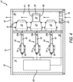
- the scent delivery system 10 includes a plurality of positioning pegs 72 positioned adjacent the exterior surface of the cartridges.
- the positioning pegs 72 make it easier to position the cartridge 22 when replacing a used one with a new one and are provided for fixing or clamping the housing portion 24 within the airflow path portion 36.
- the actuators 40 are attached via brackets 74 that are mounted on a mounting board 76 positioned in the non-airflow path portion 38.
- Another board 77 can be mounted on the opposite side of the actuators 40.
- the airflow path portion 38 is covered by a door 78 that is openable to replace the cartridges 22.
- the actuators 40 can include any type of mechanism capable of extending the arm 42 in a linear manner.
- the arm 42 is movable within a housing 80 that slidably receives the arm and houses the mechanism for extending and retracting the arm 42.
- the electronics for the actuator 40 are also preferably housed in the housing 80.
- the actuators 40 are in communication with and controlled by a controller 82 that is part of a printed circuit board or the like.
- FIG. 8 shows an exemplary embodiment of the communication between the controller 82 (which is preferably part of a PCB), the actuators 40, the fan 20, and the control panel.
- the controller and PCB are capable of communicating with the control panel (e.g., tablet, smart phone) wirelessly or on a device with buttons. It provides the actuators and fan proper input settings for selecting the proper cartridge (from user selection) and proper settings (fan speed etc.) depending on room size, scent selected, etc.
- the controller 82 is in communication with the cartridges (e.g., through RFID or other wireless communication) so that the controller 82 can identify the particular scent associated with the cartridge and to monitor the cartridge (e.g., scent oil remaining, how long the cartridge has been in use, etc.).
- the cartridge can include an RFID tag or other transmitter attached thereto and the controller can include a receiver to recognize the cartridge scent once installed. This will then populate the control pad or other human machine interface (e.g., tablet) so that it is apparent what scent is in the particular cartridge (e.g., energetic, calming, relaxing, etc.).
- the controller 82 can selectively move the covers 28 (and, therefore, the scent assemblies 30) between the open and closed positions.
- the user pushes a button or the like on the tablet or other control panel.
- the tablet communicates with the controller 82 of the scent delivery assembly 10, which, in turn, actuates the actuator 40 of the appropriate cartridge assembly 53.
- the actuator 40 is actuated arm 42 moves from the first position to the second position and the movable portion 70 (which includes the cover 28) is moved from the closed position to the open position. Because the distal end of arm 42 is engaged with opening 52, as arm 42 moves to the second position it moves base member 56, which moves the scent assembly 30 and shaft 58 together with cover 28.
- the alignment rods 66 also move within alignment openings 68.
- the controller 82 also actuates fan 20, thereby pulling air through intake opening 16 and moving air along airflow path P1. As a result of air flowing over the exposed diffusing portion 62, oil is pulled from the reservoir portion 60, is expelled through outlet opening 18 and released into the environment.
- the cartridges 22 are positioned so that the scent assemblies 30 are generally out of the air flow path P1 when the covers 28 are in the closed position, and are extended into or are aligned with the airflow path P1 when the covers 28 are in the open position.
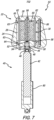
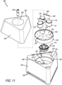
- scent delivery assembly 100 includes a main body portion 102 that defines an interior 104 and includes at least one intake opening 106 and at least one outlet opening 108. As shown in FIG. 12 , an airflow path P2 is defined between the intake opening 106 and the outlet opening 108. A fan 110 is positioned along the airflow path P2. At least one and preferably a plurality of cartridges 112 are positioned along the airflow path P2. As shown in FIG. 13 , each cartridge 112 includes a housing portion 114 that defines a housing interior 116, a first cover 118 and a scent assembly 120 positioned in the housing interior 116.
- the first cover 118 is movable between a closed position and an open position.
- the cartridge 112 includes a second cover 122 that is movable together with the first cover 118 between the closed position and the open position.
- the scent assembly 120 is positioned between the first cover 118 and the second cover 122 when the first and second covers are in the closed position and is therefore not in flow communication with the airflow path P2 when the first and second covers are in the closed position.
- the scent assembly 120 is in flow communication with the airflow path P2 when the first and second covers 118 and 122 are in the open position.
- FIG. 9 shows one cartridge 112 with the first cover 118 in the open position and the other two cartridges 112 with their first covers 118 in the closed position.
- the main body portion 102 includes a lower housing portion 124 and an upper housing portion 126 that cooperate to define the interior 104.
- the intake openings 106 are is defined in the lower housing portion 124 and the outlet opening 108 is defined in the upper housing portion 126.
- the upper housing portion 126 is hingedly connected (see hinges 128) to the lower housing portion 126.
- the upper housing portion 126 can be removable.
- the upper housing portion 126 includes openings 127 therein that are generally aligned with the cartridges 112.
- the scent delivery assembly 100 includes a removable tray portion 130 that is received in a tray portion recess 132 that is defined in the lower housing portion 124 and includes a ledge 133.
- the tray portion 130 includes a plurality of cartridge openings 134 that receive the cartridges 112.
- the housing portion 114 of the cartridges 112 is tapered and the cartridge openings 134 include a similar taper to hold the cartridges in place (the taper can be seen in FIG. 12 ), and allows them to be removed and replaced.
- the tray portion 130 and tray portion recess 132 include complementary male and female alignment members 136.
- the male alignment member is shown in the tray portion 130 and the female alignment members are shown defined in the lower housing portion 124 in the tray portion recess 132.
- the upper housing portion 126 also includes alignment members 136 for aligning with the tray portion 130
- the fan 110 is positioned in an opening 138 in the lower housing portion 124.
- the fan 110 includes tabs 140 that mate with complementary tabs 140 on the lower housing portion to position and secure the fan 110.
- FIG. 13 best shows a cartridge 112.
- the cartridge 112 includes the housing 114, with the interior 116, which is preferably a cylindrical opening, first and second covers 118 and 122 and the scent assembly 120.
- the scent assembly 120 includes an inner diffusing portion 142 and an outer reservoir portion 144.
- the second cover 122 (the lower cover) has a pivot shaft 146 extending therefrom that extends through a pivot opening 148 defined in the housing portion 114.
- the pivot shaft 146 is connected to the first cover 118 by a threaded fastener 150.
- a spring 152 (e.g., a torsion spring) is received on the pivot shaft 146 and into the pivot opening 148 and biases the first and second covers 118 and 122 toward the closed position.
- the pivot shaft 146 can extend from the first cover 118.
- the pivot shaft 146 can be removably connected (via a threaded fastener or the like) to both the first and the second cover. Similar to the first embodiment, the cartridges 112 reseal when closed to keep scent from diffusing therefrom.
- the scent delivery assembly includes a motor 154 that is operable to move the first cover 118 (and, therefore, the second cover 122) between the open and closed positions.
- the motor 154 includes an arm 156 extending therefrom that includes a finger 158 on the distal end thereof.
- the motor 154 can move the arm in a rotational manner. In use, when the arm 156 rotates the finger 158 contacts the first cover 118 of a cartridge 112 and pivots the first cover 118 to the open position.
- the arm 156 To close the first cover 118, the arm 156 continues to rotate in the same direction, and, because of the curved shape of the first cover 118, once the arm 156 passes the first cover 118, the spring 152 biases the first cover 118 back to the closed position. Because the first cover 118 is connected to the second cover 122 via the shaft 146, the second cover 122 always pivots with the first cover 118. In another embodiment, the arm can rotate the opposite direction (of the opening direction) to allow the cover to close.
- the scent delivery assembly 100 includes a controller 82 that controls the motor 154 and thereby the opening and closing of the first and second covers.
- the controller also controls the operation of the fan.
- the user pushes a button or the like on the tablet or other control panel.
- the tablet communicates with the controller 82 of the scent delivery assembly 10, which, in turn, actuates the motor 154.
- the motor 154 rotates the arm 156 such that the first cover 118 of the appropriate cartridge 112 is pivoted to the open position.
- shaft 146 is attached to second cover 122, the second cover 122 is also moved to the open position.
- This opens the scent assembly 120 to the airflow path P2.
- the controller 82 also actuates fan 110, thereby pulling air through intake openings 106 and moving air along airflow path P2.
- oil is pulled from the reservoir portion 144, is expelled through outlet opening 108 and released into the environment.
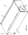
- FIGS. 14-30 show another embodiment of a scent deliver assembly or fragrance dispensing unit 310 in accordance with a preferred embodiment of the present invention.
- the fragrance dispensing unit 310 includes one or more fragrance modules 312 therein.
- the fragrance modules 312 are each configured to receive a fragrance cartridge 314.
- the present invention also includes a method or system for using or integrating a plurality of fragrance dispensing units 310 within one or more zones in an aircraft.
- the fragrance dispensing unit 310 is best shown in FIGS. 14-15 .
- the fragrance dispensing unit 310 includes a housing 316 with an inlet 318, an outlet 320 and a cover or door 322 that is pivotally connected to the housing 316.
- FIG. 15 shows the dispensing unit 310 without the door 322.
- the interior of the housing 316 includes a plurality of fragrance modules 312, a fan 324 for pulling air into the housing interior, and a tray 326.
- the fragrance modules 312 are disposed on the tray 326, which is movable out of the front of the housing so that the fragrance cartridges 314 (two are shown in FIG.
- the fragrance dispensing unit 310 can include as few as one fragrance module 312 or more than four fragrance modules 312. Any number of fragrance modules within a single fragrance dispensing unit 310 is within the scope of the present invention.
- the fragrance dispensing unit 310 is designed to contain any flames or fire within the housing.
- a flame arrester (not shown) is positioned in the interior and adjacent the outlet 320. Any type of flame arrester can be used.
- the flame arrester can be a heat exchanger that draws heat out of flame and disperses it along the housing. This type of flame arrester includes a steel honeycomb that the air goes through and is cooled to extinguish any flame.
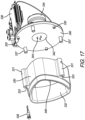
- FIGS. 16 and 17 show a fragrance module 312.
- the fragrance module 312 includes a housing 328 and a cartridge enclosure 330 that includes an opening 332 for receiving a fragrance cartridge 314 (not shown in FIGS. 16 and 17).
- FIG. 17 shows an exploded view of the interior of the fragrance module 312 with the housing omitted.
- the interior includes a motor 334, a PCB 336 in communication with the motor 334, the cartridge enclosure 330, an LED 338 and a base 340.
- the motor 334 is a DC motor.
- this is not a limitation on the present invention.
- the base 340 includes a rotatable plate 342 having a plurality of protrusions 344 extending outwardly therefrom. As described more fully below, the protrusions 344 engage with slots on the fragrance cartridge 314. In use, the motor 334 rotates the rotatable plate 342 and protrusions 344 to rotate a component in the fragrance cartridge 314 to open the fragrance cartridge 314 to expose the scent assembly.
- the scent assembly can be any component that includes the ability to wick away a scent. In a preferred embodiment, the scent assembly is taught in U.S. Patent No. 7,651,077 , the entirety of which is incorporated by reference herein.
- the cartridge enclosure 330 includes a plurality of balls or protrusions 346 that are biased inwardly into the module interior.
- the protrusions 346 cooperate with and are seated in indentations or dimples 375 defined in or on the outside of the cartridge 314. Therefore, when the cartridge 314 is loaded into the module 312 through the front opening 332 and into the module interior, the protrusions 346 are biased (by a spring or the like) into the indentations.
- the protrusions are ball bearings that are partially pressed through openings 348 in the cartridge enclosure 330 by a spring.
- the cartridge enclosure 330 includes connection protrusions 331 extending outwardly therefrom and that include openings 333 defined therein.
- the openings 333 receive posts 335 extends outwardly from the base 340.
- Long threaded fasteners (not shown) are received in the front opening 333 and extend into an opening in post 335 to secure the cartridge enclosure 330 on the base 340.
- the base 340 can also include threaded fasteners 337 that extend into openings in the back of the cartridge enclosure 330.
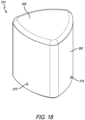
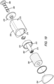
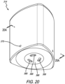
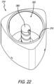
- FIGS. 18-23 show the fragrance cartridge 314, which is received in the module interior of the fragrance module 312.
- the cartridge 314 is shaped to fit into the cartridge enclosure 330 in the module 312.
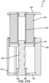
- the cartridge 314 generally includes a housing portion 350 that defines a housing interior 352, a cover 354, a movable scent assembly 356, and a communication portion 358.
- the movable scent assembly 356 includes an exteriorly threaded post 360 with female threads and an interiorly threaded cylinder 362 with male threads. The opposite threading arrangement can be used.
- the scent assembly 356 also includes a wick or scented portion 364.
- the threaded engagement of the post 360 and cylinder 362 allow the cylinder 362, on which the scented portion 364 is mounted, together with the cover 354 to move between a closed position and an open position. Rotational motion of the rotatable plate 342 is translated to linear or axial motion of the scented portion 364.
- the threaded post 360 includes a disk 366 on the bottom thereof that has slots 368 defined therein. These slots 368 receive the protrusions 344 in the module 312. Therefore, when the motor 334 turns the rotatable plate 342 and protrusions 344, as a result of the engagement of the protrusions 344 and the slots 368, the post 360 is rotated. Then, as a result of the engagement of the threads on the post 360 and cylinder 362 the post 360, scented portion 364 and cover 354 move outwardly to the open position and to expose the scented portion 364. Rotation of the rotatable plate 342 and protrusions 344 in the opposite direction causes the components to move to the closed position.
- the protrusions 344 are spring-loaded outwardly so that when the cartridge 314 is inserted into the module 312, but the slots 368 are not properly aligned, the protrusions 344 are pushed up into the slots 368 after proper alignment.
- this is not a limitation on the present invention.
- the fragrance technology is dry dispersion.
- the oils are evaporated by air being blown across a wetted wick (scent portion 364).
- the scent portion 364 includes an inner reservoir that holds the scented oil and an outer diffusing portion, similar to scent portion 30 above.
- the dry fragrances are dispersed in molecular form and preferably leave little to no residue on surfaces. The dry type preferably results in a high dispersion rate of the fragrance in cabin environment.
- the distal end of the rotatable cylinder 362 is received in a recess in the bottom of the cover 354 and includes a key 373 that is received in a corresponding slot.
- the rotatable cylinder 362 also includes a base 370 that seats the scented portion 364.
- the base 370 includes a key or protrusion 372 that is received in a slot 374 defined in the interior of the housing portion 350. The arrangement between the protrusions 372 and slot 374 help keep the components in alignment when moving between the open and closed positions.
- the indentations 376, described above, that cooperate with the protrusions 346 in the module 312 are shown in FIGS. 19-23 .
- the cartridge 314 includes near field communication technology (NFC) that communicates with NFC in the module 312, the FDU 310 or other component.
- NFC near field communication technology
- the NFC chip or the like is housed in the communication portion 358 and is positioned behind a bottom cover 378.
- FIG. 24 shows a LOPA (layout of passenger accommodation) of a VIP aircraft that includes three zones (zone 1, zone 2 and zone 3). Within each zone is an electronic control unit 380 (ECU) that contains most of the electrical components of the system for the zone (and can be mounted on a wall or the like) and two fragrance dispensing units 310 (FDU).
- the fragrance dispensing units 310 communicate with the ECU 380 via a control cable 377 (or any wired connection) (they can also communicate wirelessly).
- the control units 380 communicate with one another and with a user interface device or HMI touch screen 382 via a CAN Bus data cable 379 (or any wired connection) (they can also communicate wirelessly).
- the user interface device 382 can be any device that includes buttons (touchscreen or analog) or other controls for allowing a user to turn the fragrance dispersion on or off, up or down, etc.
- the user interface device can be integrated with or be a part of a central command unit on the aircraft that controls other features such as lights, temperature and entertainment. It will be appreciated that each zone can include a single FDU or two or more FDUs.
- the ECU includes the motor drivers for activating the motors 334 in the fragrance modules 312.
- the system includes smart cartridge technology (NFC encoding) and user error proofing (fragrance cross checking), it is modular and configurable for each custom aircraft, includes multiple fragrances, individually controlled zones, a central system control, each zone can be locally controlled, replaceable cartridges 314, dry scent technology, wired/wireless interface.
- the system does not include NFC encoding.
- each zone is controlled locally by the ECU.
- each zone, and each FDU within a zone can be controlled by a central control system or they can each be controlled separately.
- the control system can control multiple cabin zones.
- the fragrance dispersion units 310 each contain single or multiple fragrance modules 312. If multiple fragrance modules 312 are included within an FDU, each module may contain a different fragrance, or all the modules may contain the same fragrance.
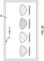
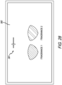
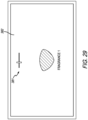
- FIGS. 25-29 show an exemplary embodiment of the graphical user interface on the controller or touchscreen 382 that is in communication with the one or more ECUs 380. It will be appreciated that this same graphical user interface can be included on the individual ECUs 380 as well.
- the fragrance cartridges 314 each contain the near field communication (NFC) chip which is encoded with information such as the name of the fragrance, the manufacturing date, a unique identifier, and a color code (unique to a fragrance) or any combination of one or more of these features.
- the NFC chip communicates with the NFC antenna or coil in the fragrance module 312, which, in turn, communicates the encoded information to the associated ECU 380.
- the fragrance name and color code are used to display information for the user on the GUI 382, as shown in FIG.
- the manufacturing date is communicated to monitor shelf life and cartridge usage life to the controller. Usage life is limited to ensure the quality of the fragrance throughout its life.
- the data is preferably encrypted to make the cartridge tamper resistant. However, in another embodiment it may not be encrypted.
- the controller keeps track of which fragrance cartridges are installed in each FDU or each zone if multiple FDU's are installed in a common zone.
- the fragrance module 312 contains the drive motor 334 to open the cartridge 314 and an NFC reader, receiver, antenna or coil (can be part of the PCB 336) to decode the NFC chip once the cartridge 314 is inserted into the fragrance module 312. Information is then transmitted from the NFC chip, to the NFC reader and to the controller or controllers (ECU) which recognize the cartridge as new or in use and then displays it as an available fragrance on the touchscreen.
- NFC reader, receiver, antenna or coil can be part of the PCB 336 to decode the NFC chip once the cartridge 314 is inserted into the fragrance module 312.
- Information is then transmitted from the NFC chip, to the NFC reader and to the controller or controllers (ECU) which recognize the cartridge as new or in use and then displays it as an available fragrance on the touchscreen.
- ECU controller or controllers
- the controller keeps track of the usage time for each cartridge, notifying the user when a cartridge should be replaced.
- a localized LED light 338 (see FIG. 17 ) on the module 312 or the FDU is used to help identify which cartridge is to be replaced.
- a cartridge 314 is "empty" (the fragrance is all consumed), it will not be displayed on the controller or touchscreen.
- each FDU includes the same scents or fragrances therein. In other words, if Fragrance 1 is included in the first FDU, but not in the second FDU, the controller will alert the user that there is an issue in that the fragrances do not match.
- FIG. 30 shows an environmental control system for a commercial aircraft 200 and how the fragrance dispensing system can be integrated into the ECS.
- the fragrance dispensing system taught herein can be integrated into the typical aircraft environmental control system (ECS) in any aircraft.
- ECS aircraft environmental control system
- compressed air is taken off the engines 386, the auxiliary power unit (APU) 388 or a ground cart (not shown).
- the air then goes through the air conditioning packs 389 to cool it through a process of compression and expansion cycles.
- the air is fed into a mixer unit 390 where it is mixed with recirculated cabin air.
- the air is then fed through a hot air manifold or heat exchanger 391.
- An alternate method for temperature controls is to pump uncooled bleed air into the mixer unit as well. From there, the conditioned and temperature controlled air is fed into the cabin. There are different duct lines 392 for different zones in the cabin.
- the aircraft 200 in the exemplary embodiment includes eight passenger zones and the flight deck, as well as ducts leading to the cargo compartments. Some of the air that is displaced from the cabin is dumped overboard and some is recirculated back into the mixer unit.
- the fragrance can be introduced in the ducts 392 between the mixer unit 390 and the zones or cabin sections. This allows for fragrance scenting cabin areas independently (e.g,. different classes can be scented differently).
- the system shown in FIG. 24 can be used, except that the FDUs (see the exemplary FDUs 396 in FIG. 30 ) are positioned in or adjacent the ducts 392 to release fragrance into the ducts 392 as opposed to being located in a cabinet or other location within the zone.
Landscapes
- Health & Medical Sciences (AREA)
- Epidemiology (AREA)
- Life Sciences & Earth Sciences (AREA)
- Animal Behavior & Ethology (AREA)
- General Health & Medical Sciences (AREA)
- Public Health (AREA)
- Veterinary Medicine (AREA)
- Disinfection, Sterilisation Or Deodorisation Of Air (AREA)
- Air-Conditioning For Vehicles (AREA)
Claims (10)
- Flugzeug (200), umfassend:einen Rumpf, der ein Kabineninneres definiert, das mindestens eine erste und zweite Zone beinhaltet, undein Umgebungssteuersystem, das Folgendes beinhalteteine Luftquelle, wobei Luft zwischen der Luftquelle und dem Kabineninneren entlang eines Luftstromwegs (P1) strömt,eine Mischereinheit (390) in Luftstromverbindung mit der Luftquelle und stromabwärts von der Luftquelle in dem Luftstromweg positioniert, wobei die Mischereinheit dazu konfiguriert ist, mit Luft von der Luftquelle versorgt zu werden, und die Luft von der Luftquelle mit rückgeführter Kabinenluft zu mischen;mindestens einen ersten und einen zweiten Luftkanal (392), die in dem Luftstromweg zwischen der Mischereinheit und dem Kabineninneren positioniert sind,eine erste Duftabgabeeinheit (310, 394, 396), die zwischen der Mischereinheit und dem Kabineninneren entlang des Luftstromwegs positioniert ist, wobei die erste Duftabgabeeinheit dazu konfiguriert ist, einen ersten Duft in den ersten Kanal entlang des Luftstromwegs und in die erste Zone abzugeben, undeine zweite Duftabgabeeinheit, die zwischen der Mischereinheit und dem Kabineninneren entlang des Luftstromwegs positioniert ist, wobei die zweite Duftabgabeeinheit dazu konfiguriert ist, den ersten Duft in den zweiten Kanal entlang des Luftstromwegs und in die zweite Zone abzugeben.
- Flugzeug nach Anspruch 1, wobei die erste Duftabgabeeinheit (310, 394, 396) eine Duftstoffanordnung (30, 356) beinhaltet, die ein erstes Duftöl, das den ersten Duft umfasst, enthält.
- Flugzeug nach Anspruch 2, wobei die erste Duftabgabeeinheit (310, 394, 396) dazu konfiguriert ist, selektiv mindestens einen ersten und einen zweiten Duftstoff in den Luftstromweg abzugeben.
- Flugzeug nach Anspruch 1, wobei die erste Duftabgabeeinheit (310, 394, 396) dazu konfiguriert ist, den ersten Duft in die Mischereinheit (390) abzugeben.
- Flugzeug nach Anspruch 4, wobei die erste Duftabgabeeinheit (310, 394, 396) eine erste Duftpatrone (314) darin beinhaltet, die eine Duftstoffanordnung (30, 356) mit dem ersten Duft darin beinhaltet, wobei die erste Duftpatrone eine Abdeckung (118, 122) beinhaltet, die zwischen einer geschlossenen Position und einer offenen Position bewegbar ist, wobei der erste Duft abgegeben wird, wenn sich die Abdeckung in der offenen Position befindet.
- Flugzeug nach Anspruch 5, wobei die erste Duftabgabeeinheit (310, 394, 396) eine zweite Duftpatrone (314) darin beinhaltet, die eine Duftstoffanordnung (30, 356) mit einem zweiten Duft darin beinhaltet, wobei die zweite Duftpatrone eine Abdeckung (118, 122) beinhaltet, die zwischen einer geschlossenen Position und einer offenen Position bewegbar ist, wobei der zweite Duft abgegeben wird, wenn sich die Abdeckung in der offenen Position befindet.
- Flugzeug nach Anspruch 1, wobei die erste Duftabgabeeinheit (310, 394, 396) dazu konfiguriert ist, selektiv mindestens einen ersten und zweiten Duft in den ersten Kanal (392) abzugeben, und wobei die zweite Duftabgabeeinheit dazu konfiguriert ist, selektiv mindestens einen ersten und zweiten Duft in den zweiten Kanal (392) abzugeben.
- Flugzeug nach Anspruch 7, wobei die erste Duftabgabeeinheit (310, 394, 396) eine erste Duftpatrone (314) darin beinhaltet, die eine Duftstoffanordnung (30, 356) mit dem ersten Duft beinhaltet, wobei die erste Duftpatrone eine Abdeckung (118, 122) beinhaltet, die zwischen einer geschlossenen und einer offenen Position bewegbar ist, wobei der erste Duft abgegeben wird, wenn sich die Abdeckung in der offenen Position befindet, wobei die erste Duftabgabeeinheit eine zweite Duftpatrone (314) darin beinhaltet, die eine Duftstoffanordnung (30, 356) mit dem zweiten Duft darin beinhaltet, wobei die zweite Duftpatrone eine Abdeckung (118, 122) beinhaltet, die zwischen einer geschlossenen und einer offenen Position bewegbar ist, wobei der zweite Duft abgegeben wird, wenn sich die Abdeckung in der offenen Position befindet.
- Flugzeug nach Anspruch 1, wobei die Duftabgabeeinheit (310, 394, 396) in elektrischer Verbindung mit einer elektrischen Steuereinheit (380) steht, wobei die erste Duftabgabeeinheit dazu konfiguriert ist, den ersten Duft basierend auf Anweisungen von der elektrischen Steuereinheit selektiv abzugeben.
- Flugzeug nach Anspruch 9, wobei die elektrische Steuereinheit (380) eine Mensch-Maschine-Schnittstelle (382) beinhaltet und wobei die Anweisungen durch menschliche Eingabe bereitgestellt werden können.
Applications Claiming Priority (3)
| Application Number | Priority Date | Filing Date | Title |
|---|---|---|---|
| US201662340378P | 2016-05-23 | 2016-05-23 | |
| US201662414504P | 2016-10-28 | 2016-10-28 | |
| PCT/US2017/034062 WO2017205418A1 (en) | 2016-05-23 | 2017-05-23 | Fragrance delivery system |
Publications (3)
| Publication Number | Publication Date |
|---|---|
| EP3463589A1 EP3463589A1 (de) | 2019-04-10 |
| EP3463589A4 EP3463589A4 (de) | 2020-09-30 |
| EP3463589B1 true EP3463589B1 (de) | 2025-07-09 |
Family
ID=60412904
Family Applications (1)
| Application Number | Title | Priority Date | Filing Date |
|---|---|---|---|
| EP17803450.0A Active EP3463589B1 (de) | 2016-05-23 | 2017-05-23 | Flugzeug mit duftabgabesystem |
Country Status (3)
| Country | Link |
|---|---|
| EP (1) | EP3463589B1 (de) |
| CA (1) | CA3025262C (de) |
| WO (1) | WO2017205418A1 (de) |
Families Citing this family (4)
| Publication number | Priority date | Publication date | Assignee | Title |
|---|---|---|---|---|
| FR3084268B1 (fr) * | 2018-07-27 | 2024-03-08 | Artiris | Cartouche pour un dispositif de diffusion de fragrances et dispositif pour la diffusion de fragrances |
| CN110916254B (zh) * | 2018-09-04 | 2023-07-25 | 贵州中烟工业有限责任公司 | 一种提高加热不燃烧烟草逐口抽吸一致性的装置 |
| US11780590B2 (en) | 2020-08-14 | 2023-10-10 | Honeywell International Inc. | Aircraft cabin disinfection |
| DE102021104976B4 (de) | 2021-03-02 | 2023-04-13 | Diehl Aviation Laupheim Gmbh | Anordnung für ein Flugzeug mit einer Vorrichtung zur Abgabe eines Duft- und/oder Luftbefeuchtungsmittels sowie Verfahren zur Befestigung der Vorrichtung |
Citations (2)
| Publication number | Priority date | Publication date | Assignee | Title |
|---|---|---|---|---|
| WO2007087709A1 (en) * | 2006-01-31 | 2007-08-09 | Peter Klaptchuk | Sanitization of aircraft or vehicle cabin |
| US20140004783A1 (en) * | 2012-06-28 | 2014-01-02 | Air Raider Freshner, LLC | Selectively changeable air freshener |
Family Cites Families (13)
| Publication number | Priority date | Publication date | Assignee | Title |
|---|---|---|---|---|
| US3259050A (en) * | 1963-10-31 | 1966-07-05 | Colgate Palmolive Co | Air modifying system for vehicles |
| JP2547279B2 (ja) * | 1989-12-15 | 1996-10-23 | 株式会社マスダハーモ | 空気循環装置 |
| US5429180A (en) * | 1992-10-02 | 1995-07-04 | Nippondenso Co., Ltd. | Perfume generating device |
| US5924597A (en) * | 1997-09-19 | 1999-07-20 | Lynn; David M. | Building fragrance distribution system and method |
| WO2001030404A1 (en) * | 1999-10-29 | 2001-05-03 | E. One Co., Ltd. | Scent diffusion apparatus and method thereof |
| US20050220664A1 (en) * | 2002-09-23 | 2005-10-06 | Venta-Duft Gmbh | Aroma cartridge and device for dispensing aroma substances, and control or regulation method |
| US20070041865A1 (en) * | 2005-08-17 | 2007-02-22 | Ayoub Ramy P | Electronic system and methods of dispensing a scent and antidote |
| US8931712B2 (en) * | 2009-02-05 | 2015-01-13 | Valeo Japan Co., Ltd. | Fragrance device for vehicle and sealing component used therein |
| US8170405B2 (en) * | 2009-03-27 | 2012-05-01 | Harris Robert M | Multipurpose cartridge-based liquid dispensing air freshener system |
| US9352063B2 (en) * | 2013-07-23 | 2016-05-31 | Lashell Ooten | HVAC fragrance system |
| KR101620202B1 (ko) * | 2014-10-13 | 2016-05-24 | 현대자동차주식회사 | 차량용 방향장치 |
| US9808550B2 (en) * | 2015-03-12 | 2017-11-07 | Pacific Precision Products Mfg. | Scent delivery system |
| EP3439960B1 (de) * | 2016-04-04 | 2023-08-16 | B/E Aerospace, Inc. | Luftbehandlungssystem |
-
2017
- 2017-05-23 EP EP17803450.0A patent/EP3463589B1/de active Active
- 2017-05-23 CA CA3025262A patent/CA3025262C/en active Active
- 2017-05-23 WO PCT/US2017/034062 patent/WO2017205418A1/en not_active Ceased
Patent Citations (2)
| Publication number | Priority date | Publication date | Assignee | Title |
|---|---|---|---|---|
| WO2007087709A1 (en) * | 2006-01-31 | 2007-08-09 | Peter Klaptchuk | Sanitization of aircraft or vehicle cabin |
| US20140004783A1 (en) * | 2012-06-28 | 2014-01-02 | Air Raider Freshner, LLC | Selectively changeable air freshener |
Also Published As
| Publication number | Publication date |
|---|---|
| CA3025262A1 (en) | 2017-11-30 |
| CA3025262C (en) | 2020-03-24 |
| EP3463589A1 (de) | 2019-04-10 |
| WO2017205418A1 (en) | 2017-11-30 |
| EP3463589A4 (de) | 2020-09-30 |
Similar Documents
| Publication | Publication Date | Title |
|---|---|---|
| US10287021B2 (en) | Fragrance delivery system | |
| US10913539B2 (en) | Fragrance delivery system | |
| EP3463589B1 (de) | Flugzeug mit duftabgabesystem | |
| US9808550B2 (en) | Scent delivery system | |
| EP3439960B1 (de) | Luftbehandlungssystem | |
| US6929218B1 (en) | Modularized integrated aircraft seat structure | |
| US20080121757A1 (en) | Passenger seats | |
| US10237511B2 (en) | Projection information display | |
| US10452243B2 (en) | System and method of operation of the system incorporating a graphical user interface in a side ledge of a vehicle cabin | |
| US9205914B1 (en) | Distributed architecture for a system and a method of operation of the system incorporating a graphical user interface controlling functions in a vehicle cabin | |
| EP3922557B1 (de) | Persönliches flugzeugsitzluftbehandlungssystem | |
| US20160059954A1 (en) | System and a method of operation of the system incorporating a graphical user interface on a mobile computing device for a passenger in a vehicle cabin | |
| CA3005943C (en) | System for and method of controlling functions in a vehicle cabin | |
| WO2020208420A1 (en) | Air gasper with integrated fan | |
| CN108475131A (zh) | 用于控制交通工具舱中的功能的系统和方法 | |
| EP3674216A1 (de) | Universelle passagierserviceeinheit | |
| CN108370383B (zh) | 用于表示飞机机舱中的故障的位置的系统和方法 | |
| EP3752254B1 (de) | Behälteranordnung für flugzeugsauerstoffmasken | |
| US12296958B2 (en) | Passenger selectable power mode operation for aircraft cabin environment | |
| US20250299641A1 (en) | Customizable veneer |
Legal Events
| Date | Code | Title | Description |
|---|---|---|---|
| STAA | Information on the status of an ep patent application or granted ep patent |
Free format text: STATUS: THE INTERNATIONAL PUBLICATION HAS BEEN MADE |
|
| PUAI | Public reference made under article 153(3) epc to a published international application that has entered the european phase |
Free format text: ORIGINAL CODE: 0009012 |
|
| STAA | Information on the status of an ep patent application or granted ep patent |
Free format text: STATUS: REQUEST FOR EXAMINATION WAS MADE |
|
| 17P | Request for examination filed |
Effective date: 20181220 |
|
| AK | Designated contracting states |
Kind code of ref document: A1 Designated state(s): AL AT BE BG CH CY CZ DE DK EE ES FI FR GB GR HR HU IE IS IT LI LT LU LV MC MK MT NL NO PL PT RO RS SE SI SK SM TR |
|
| AX | Request for extension of the european patent |
Extension state: BA ME |
|
| DAV | Request for validation of the european patent (deleted) | ||
| DAX | Request for extension of the european patent (deleted) | ||
| RIC1 | Information provided on ipc code assigned before grant |
Ipc: A61L 9/12 20060101ALI20200424BHEP Ipc: A62B 7/08 20060101ALI20200424BHEP Ipc: A62B 7/14 20060101AFI20200424BHEP |
|
| A4 | Supplementary search report drawn up and despatched |
Effective date: 20200831 |
|
| RIC1 | Information provided on ipc code assigned before grant |
Ipc: A61L 9/12 20060101ALI20200825BHEP Ipc: A62B 7/14 20060101AFI20200825BHEP Ipc: A62B 7/08 20060101ALI20200825BHEP |
|
| STAA | Information on the status of an ep patent application or granted ep patent |
Free format text: STATUS: EXAMINATION IS IN PROGRESS |
|
| 17Q | First examination report despatched |
Effective date: 20220524 |
|
| GRAP | Despatch of communication of intention to grant a patent |
Free format text: ORIGINAL CODE: EPIDOSNIGR1 |
|
| STAA | Information on the status of an ep patent application or granted ep patent |
Free format text: STATUS: GRANT OF PATENT IS INTENDED |
|
| INTG | Intention to grant announced |
Effective date: 20250127 |
|
| GRAS | Grant fee paid |
Free format text: ORIGINAL CODE: EPIDOSNIGR3 |
|
| GRAA | (expected) grant |
Free format text: ORIGINAL CODE: 0009210 |
|
| STAA | Information on the status of an ep patent application or granted ep patent |
Free format text: STATUS: THE PATENT HAS BEEN GRANTED |
|
| RAP1 | Party data changed (applicant data changed or rights of an application transferred) |
Owner name: AVOX SYSTEMS INC. |
|
| AK | Designated contracting states |
Kind code of ref document: B1 Designated state(s): AL AT BE BG CH CY CZ DE DK EE ES FI FR GB GR HR HU IE IS IT LI LT LU LV MC MK MT NL NO PL PT RO RS SE SI SK SM TR |
|
| REG | Reference to a national code |
Ref country code: GB Ref legal event code: FG4D |
|
| REG | Reference to a national code |
Ref country code: CH Ref legal event code: EP |
|
| REG | Reference to a national code |
Ref country code: IE Ref legal event code: FG4D |
|
| REG | Reference to a national code |
Ref country code: DE Ref legal event code: R096 Ref document number: 602017090484 Country of ref document: DE |
|
| REG | Reference to a national code |
Ref country code: NL Ref legal event code: MP Effective date: 20250709 |
|
| PG25 | Lapsed in a contracting state [announced via postgrant information from national office to epo] |
Ref country code: PT Free format text: LAPSE BECAUSE OF FAILURE TO SUBMIT A TRANSLATION OF THE DESCRIPTION OR TO PAY THE FEE WITHIN THE PRESCRIBED TIME-LIMIT Effective date: 20251110 |
|
| PG25 | Lapsed in a contracting state [announced via postgrant information from national office to epo] |
Ref country code: NL Free format text: LAPSE BECAUSE OF FAILURE TO SUBMIT A TRANSLATION OF THE DESCRIPTION OR TO PAY THE FEE WITHIN THE PRESCRIBED TIME-LIMIT Effective date: 20250709 |
|
| REG | Reference to a national code |
Ref country code: AT Ref legal event code: MK05 Ref document number: 1811321 Country of ref document: AT Kind code of ref document: T Effective date: 20250709 |
|
| PG25 | Lapsed in a contracting state [announced via postgrant information from national office to epo] |
Ref country code: IS Free format text: LAPSE BECAUSE OF FAILURE TO SUBMIT A TRANSLATION OF THE DESCRIPTION OR TO PAY THE FEE WITHIN THE PRESCRIBED TIME-LIMIT Effective date: 20251109 |
|
| PG25 | Lapsed in a contracting state [announced via postgrant information from national office to epo] |
Ref country code: NO Free format text: LAPSE BECAUSE OF FAILURE TO SUBMIT A TRANSLATION OF THE DESCRIPTION OR TO PAY THE FEE WITHIN THE PRESCRIBED TIME-LIMIT Effective date: 20251009 |
|
| REG | Reference to a national code |
Ref country code: LT Ref legal event code: MG9D |
|
| PG25 | Lapsed in a contracting state [announced via postgrant information from national office to epo] |
Ref country code: AT Free format text: LAPSE BECAUSE OF FAILURE TO SUBMIT A TRANSLATION OF THE DESCRIPTION OR TO PAY THE FEE WITHIN THE PRESCRIBED TIME-LIMIT Effective date: 20250709 |
|
| PG25 | Lapsed in a contracting state [announced via postgrant information from national office to epo] |
Ref country code: FI Free format text: LAPSE BECAUSE OF FAILURE TO SUBMIT A TRANSLATION OF THE DESCRIPTION OR TO PAY THE FEE WITHIN THE PRESCRIBED TIME-LIMIT Effective date: 20250709 |
|
| PG25 | Lapsed in a contracting state [announced via postgrant information from national office to epo] |
Ref country code: HR Free format text: LAPSE BECAUSE OF FAILURE TO SUBMIT A TRANSLATION OF THE DESCRIPTION OR TO PAY THE FEE WITHIN THE PRESCRIBED TIME-LIMIT Effective date: 20250709 |
|
| PG25 | Lapsed in a contracting state [announced via postgrant information from national office to epo] |
Ref country code: GR Free format text: LAPSE BECAUSE OF FAILURE TO SUBMIT A TRANSLATION OF THE DESCRIPTION OR TO PAY THE FEE WITHIN THE PRESCRIBED TIME-LIMIT Effective date: 20251010 |
|
| PG25 | Lapsed in a contracting state [announced via postgrant information from national office to epo] |
Ref country code: SE Free format text: LAPSE BECAUSE OF FAILURE TO SUBMIT A TRANSLATION OF THE DESCRIPTION OR TO PAY THE FEE WITHIN THE PRESCRIBED TIME-LIMIT Effective date: 20250709 |
|
| PG25 | Lapsed in a contracting state [announced via postgrant information from national office to epo] |
Ref country code: LV Free format text: LAPSE BECAUSE OF FAILURE TO SUBMIT A TRANSLATION OF THE DESCRIPTION OR TO PAY THE FEE WITHIN THE PRESCRIBED TIME-LIMIT Effective date: 20250709 |
|
| PG25 | Lapsed in a contracting state [announced via postgrant information from national office to epo] |
Ref country code: PL Free format text: LAPSE BECAUSE OF FAILURE TO SUBMIT A TRANSLATION OF THE DESCRIPTION OR TO PAY THE FEE WITHIN THE PRESCRIBED TIME-LIMIT Effective date: 20250709 Ref country code: BG Free format text: LAPSE BECAUSE OF FAILURE TO SUBMIT A TRANSLATION OF THE DESCRIPTION OR TO PAY THE FEE WITHIN THE PRESCRIBED TIME-LIMIT Effective date: 20250709 |
|
| PG25 | Lapsed in a contracting state [announced via postgrant information from national office to epo] |
Ref country code: RS Free format text: LAPSE BECAUSE OF FAILURE TO SUBMIT A TRANSLATION OF THE DESCRIPTION OR TO PAY THE FEE WITHIN THE PRESCRIBED TIME-LIMIT Effective date: 20251009 |
|
| PG25 | Lapsed in a contracting state [announced via postgrant information from national office to epo] |
Ref country code: ES Free format text: LAPSE BECAUSE OF FAILURE TO SUBMIT A TRANSLATION OF THE DESCRIPTION OR TO PAY THE FEE WITHIN THE PRESCRIBED TIME-LIMIT Effective date: 20250709 |
|
| PG25 | Lapsed in a contracting state [announced via postgrant information from national office to epo] |
Ref country code: SM Free format text: LAPSE BECAUSE OF FAILURE TO SUBMIT A TRANSLATION OF THE DESCRIPTION OR TO PAY THE FEE WITHIN THE PRESCRIBED TIME-LIMIT Effective date: 20250709 |
|
| PG25 | Lapsed in a contracting state [announced via postgrant information from national office to epo] |
Ref country code: DK Free format text: LAPSE BECAUSE OF FAILURE TO SUBMIT A TRANSLATION OF THE DESCRIPTION OR TO PAY THE FEE WITHIN THE PRESCRIBED TIME-LIMIT Effective date: 20250709 |
|
| PG25 | Lapsed in a contracting state [announced via postgrant information from national office to epo] |
Ref country code: IT Free format text: LAPSE BECAUSE OF FAILURE TO SUBMIT A TRANSLATION OF THE DESCRIPTION OR TO PAY THE FEE WITHIN THE PRESCRIBED TIME-LIMIT Effective date: 20250709 |
|
| PG25 | Lapsed in a contracting state [announced via postgrant information from national office to epo] |
Ref country code: CZ Free format text: LAPSE BECAUSE OF FAILURE TO SUBMIT A TRANSLATION OF THE DESCRIPTION OR TO PAY THE FEE WITHIN THE PRESCRIBED TIME-LIMIT Effective date: 20250709 |
|
| PG25 | Lapsed in a contracting state [announced via postgrant information from national office to epo] |
Ref country code: SK Free format text: LAPSE BECAUSE OF FAILURE TO SUBMIT A TRANSLATION OF THE DESCRIPTION OR TO PAY THE FEE WITHIN THE PRESCRIBED TIME-LIMIT Effective date: 20250709 Ref country code: EE Free format text: LAPSE BECAUSE OF FAILURE TO SUBMIT A TRANSLATION OF THE DESCRIPTION OR TO PAY THE FEE WITHIN THE PRESCRIBED TIME-LIMIT Effective date: 20250709 |