EP3462809B1 - Verfahren zur befestigung von sammelschienen an kohlenstoffallotrop-enteisungsbahnen - Google Patents
Verfahren zur befestigung von sammelschienen an kohlenstoffallotrop-enteisungsbahnen Download PDFInfo
- Publication number
- EP3462809B1 EP3462809B1 EP18196284.6A EP18196284A EP3462809B1 EP 3462809 B1 EP3462809 B1 EP 3462809B1 EP 18196284 A EP18196284 A EP 18196284A EP 3462809 B1 EP3462809 B1 EP 3462809B1
- Authority
- EP
- European Patent Office
- Prior art keywords
- carbon allotrope
- heater element
- alloys
- wetting layer
- carbon
- Prior art date
- Legal status (The legal status is an assumption and is not a legal conclusion. Google has not performed a legal analysis and makes no representation as to the accuracy of the status listed.)
- Active
Links
Images
Classifications
-
- H—ELECTRICITY
- H05—ELECTRIC TECHNIQUES NOT OTHERWISE PROVIDED FOR
- H05B—ELECTRIC HEATING; ELECTRIC LIGHT SOURCES NOT OTHERWISE PROVIDED FOR; CIRCUIT ARRANGEMENTS FOR ELECTRIC LIGHT SOURCES, IN GENERAL
- H05B3/00—Ohmic-resistance heating
- H05B3/10—Heating elements characterised by the composition or nature of the materials or by the arrangement of the conductor
- H05B3/12—Heating elements characterised by the composition or nature of the materials or by the arrangement of the conductor characterised by the composition or nature of the conductive material
- H05B3/14—Heating elements characterised by the composition or nature of the materials or by the arrangement of the conductor characterised by the composition or nature of the conductive material the material being non-metallic
- H05B3/145—Carbon only, e.g. carbon black, graphite
-
- C—CHEMISTRY; METALLURGY
- C01—INORGANIC CHEMISTRY
- C01B—NON-METALLIC ELEMENTS; COMPOUNDS THEREOF; METALLOIDS OR COMPOUNDS THEREOF NOT COVERED BY SUBCLASS C01C
- C01B32/00—Carbon; Compounds thereof
- C01B32/15—Nano-sized carbon materials
- C01B32/158—Carbon nanotubes
- C01B32/168—After-treatment
-
- C—CHEMISTRY; METALLURGY
- C01—INORGANIC CHEMISTRY
- C01B—NON-METALLIC ELEMENTS; COMPOUNDS THEREOF; METALLOIDS OR COMPOUNDS THEREOF NOT COVERED BY SUBCLASS C01C
- C01B32/00—Carbon; Compounds thereof
- C01B32/15—Nano-sized carbon materials
- C01B32/182—Graphene
- C01B32/194—After-treatment
-
- C—CHEMISTRY; METALLURGY
- C01—INORGANIC CHEMISTRY
- C01B—NON-METALLIC ELEMENTS; COMPOUNDS THEREOF; METALLOIDS OR COMPOUNDS THEREOF NOT COVERED BY SUBCLASS C01C
- C01B32/00—Carbon; Compounds thereof
- C01B32/20—Graphite
- C01B32/21—After-treatment
-
- H—ELECTRICITY
- H05—ELECTRIC TECHNIQUES NOT OTHERWISE PROVIDED FOR
- H05B—ELECTRIC HEATING; ELECTRIC LIGHT SOURCES NOT OTHERWISE PROVIDED FOR; CIRCUIT ARRANGEMENTS FOR ELECTRIC LIGHT SOURCES, IN GENERAL
- H05B3/00—Ohmic-resistance heating
- H05B3/02—Details
- H05B3/03—Electrodes
-
- H—ELECTRICITY
- H05—ELECTRIC TECHNIQUES NOT OTHERWISE PROVIDED FOR
- H05B—ELECTRIC HEATING; ELECTRIC LIGHT SOURCES NOT OTHERWISE PROVIDED FOR; CIRCUIT ARRANGEMENTS FOR ELECTRIC LIGHT SOURCES, IN GENERAL
- H05B3/00—Ohmic-resistance heating
- H05B3/20—Heating elements having extended surface area substantially in a two-dimensional [2D] plane, e.g. plate-heater
- H05B3/34—Heating elements having extended surface area substantially in a two-dimensional [2D] plane, e.g. plate-heater flexible, e.g. heating nets or webs
-
- B—PERFORMING OPERATIONS; TRANSPORTING
- B64—AIRCRAFT; AVIATION; COSMONAUTICS
- B64D—EQUIPMENT FOR FITTING IN OR TO AIRCRAFT; FLIGHT SUITS; PARACHUTES; ARRANGEMENT OR MOUNTING OF POWER PLANTS OR PROPULSION TRANSMISSIONS IN AIRCRAFT
- B64D15/00—De-icing or preventing icing on exterior surfaces of aircraft
- B64D15/12—De-icing or preventing icing on exterior surfaces of aircraft by electric heating
-
- H—ELECTRICITY
- H05—ELECTRIC TECHNIQUES NOT OTHERWISE PROVIDED FOR
- H05B—ELECTRIC HEATING; ELECTRIC LIGHT SOURCES NOT OTHERWISE PROVIDED FOR; CIRCUIT ARRANGEMENTS FOR ELECTRIC LIGHT SOURCES, IN GENERAL
- H05B2203/00—Aspects relating to Ohmic resistive heating covered by group H05B3/00
- H05B2203/011—Heaters using laterally extending conductive material as connecting means
-
- H—ELECTRICITY
- H05—ELECTRIC TECHNIQUES NOT OTHERWISE PROVIDED FOR
- H05B—ELECTRIC HEATING; ELECTRIC LIGHT SOURCES NOT OTHERWISE PROVIDED FOR; CIRCUIT ARRANGEMENTS FOR ELECTRIC LIGHT SOURCES, IN GENERAL
- H05B2203/00—Aspects relating to Ohmic resistive heating covered by group H05B3/00
- H05B2203/013—Heaters using resistive films or coatings
-
- H—ELECTRICITY
- H05—ELECTRIC TECHNIQUES NOT OTHERWISE PROVIDED FOR
- H05B—ELECTRIC HEATING; ELECTRIC LIGHT SOURCES NOT OTHERWISE PROVIDED FOR; CIRCUIT ARRANGEMENTS FOR ELECTRIC LIGHT SOURCES, IN GENERAL
- H05B2203/00—Aspects relating to Ohmic resistive heating covered by group H05B3/00
- H05B2203/017—Manufacturing methods or apparatus for heaters
-
- H—ELECTRICITY
- H05—ELECTRIC TECHNIQUES NOT OTHERWISE PROVIDED FOR
- H05B—ELECTRIC HEATING; ELECTRIC LIGHT SOURCES NOT OTHERWISE PROVIDED FOR; CIRCUIT ARRANGEMENTS FOR ELECTRIC LIGHT SOURCES, IN GENERAL
- H05B2214/00—Aspects relating to resistive heating, induction heating and heating using microwaves, covered by groups H05B3/00, H05B6/00
- H05B2214/04—Heating means manufactured by using nanotechnology
Definitions
- This application relates generally to aircraft ice protection, and specifically to de-icing sheets.
- Electro-thermal de-icing systems typically use metal wires to resistively melt ice by converting electrical energy to thermal energy.
- the use of metal wires as resistance elements embedded in de-icing systems presents several problems, including element durability, parasitic weight, limited damage tolerance and low power efficiency.
- Carbon nanotube (CNT) materials have been proposed as an alternative to metal wire or foil heating elements in ice protection systems.
- CNTs are carbon allotropes having a generally cylindrical nanostructure. They have unusual properties that make them valuable for many different technologies. For instance, some CNTs can have high thermal and electrical conductivity, making them suitable for replacing metal heating elements. Due to their much lighter mass, substituting CNTs for metal heating components can reduce the overall weight of a heating component significantly. This makes the use of CNTs of particular interest for applications where weight is critical, such as in aerospace and aviation technologies.
- sheets or films containing CNTs are difficult to connect to an electrical circuit. For instance, bus bar attachment to CNT sheets is quite difficult, as metallic bus bars do not wet to carbon allotropes. Thus, connecting metal wires, for example via soldering, to a CNT heater can be challenging.
- US2014/151353A1 discloses a heater element according to the preamble of claim 11.
- Typical metal heating circuits are commonly created by photochemically etching metallic alloy foils on a substrate and subsequently building electrothermal heater composites. This method suffers from insufficient reliability due to over- or under-etching, photoresist alignment issues, and delamination, in addition to poor substrate adhesion. Additionally, this type of etching is time consuming, wasteful, and environmentally detrimental.
- a method of making a conformal coating on a carbon allotrope heater element comprising: applying a wetting agent to a portion of the carbon allotrope heater element to create a wetting layer, wherein the wetting agent is selected from the group consisting of carbides, oxides, and nitrides; introducing a metallic material onto the portion of the carbon allotrope heater element with the wetting layer; and melting the metallic material such that it wets the portion of the carbon allotrope heater element with the wetting layer.
- a carbon allotrope heater element comprises: a carbon allotrope material; and a metallic coating on a portion of the carbon allotrope material, the metallic coating being bonded to the carbon allotrope material by a wetting layer selected from the group consisting of carbides, oxides, and nitrides.
- Heating circuits are used for a variety of ice protection purposes.
- the use of carbon nanotubes and other types of carbon allotropes allows for tailored resistivity and increased power efficiency for ice protection applications.
- carbon nanotube heater elements are difficult to connect to bus bars for electrical connection to the de-icing circuit.
- this application presents a method of attaching metallic bus bars to carbon heater elements using a surface modification of the carbon allotrope, including a wetting layer.
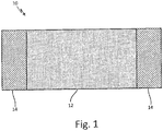
- FIG. 1 is a schematic view of a carbon allotrope heater sheet with bus bar attachments.
- Carbon allotrope heater sheet 10 includes main portion 12 and coated portions 14.
- Carbon allotrope heater sheet can be, for example, made of carbon nanotubes (CNT), and can be woven or non-woven, knitted, braided, self-assembled, vapor deposited, solution cast, planar or nonplanar, or three dimensional.
- sheet 10 can be made of a different carbon allotrope, including at least one of graphene, graphene nanoribbons (GNRs), graphite or other suitably conductive form of carbon.
- GNRs graphene nanoribbons
- Coated portions 14 allow for electrical connection to sheet 10. For instance, wires can be soldered onto coated portions 14.
- Coated portions 14 are comprised of a metallic material, such as copper or copper alloys, aluminum or aluminum alloys, nickel or its alloys, platinum or platinum alloys, silver or silver alloys, solder alloys, braze alloys, other suitably conductive metals or semimetals, or combinations thereof.
- Coated portions are applied to sheet 10 through a wetting layer capable of allowing at least partial infiltration or coating of sheet 10 by metallic material.
- the wetting layer can be comprised of Mo 2 C, TiC, NiO, Fe 2 O 3 , Cr 3 C 2 , WC or other suitable carbides, oxides or nitrides. The wetting layer is applied to sheet 10 prior to the metallic material. The process of making sheet 10 with coated portions 14 is explained in reference to FIG. 2 below.
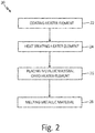
- FIG. 2 is a flow chart depicting a method of making a carbon allotrope heater sheet, such as a CNT heater sheet, with bus bar attachments.
- Method 20 includes coating a heater element (step 22), heat treating the heater element (step 24), placing a metallic material onto the heater element (26), and melting the metallic material (step 28).
- Method 20 in FIG. 2 results in an article such as heater sheet 10 of FIG. 1 .
- Method 20 starts with creating a wetting layer on a heater element in step 22.
- the heater element can be a carbon allotrope suitable for ice protection, such as carbon nanotubes, graphene, graphene nanoribbons (GNRs), graphite or other suitably conductive form of carbon.
- GNRs graphene nanoribbons
- boron nitride nanotubes or similar material can be used.
- heater elements can range widely in size from a few square centimeters to hundreds of square centimeters, for example, a heater can be less than one square inch (645.16 square millimetres), or a panel of 50 by 100 inches (127 by 254 centimetres).
- the heater element can be a sheet that is woven or non-woven (as described in more detail with reference to FIG. 1 ), depending on its ultimate application for ice protection (e.g., what part of the aircraft it may be applied to and the ice protection needs of that part).
- the heater element can be a single wire, cable or ribbon structure, or bundles of such structures, comprising the carbon allotrope.
- the heater element can be a three dimensional heater element, such as a heater element with varying thicknesses as required by the shape of a part needing ice protection (such a heating element with varying thicknesses would have varying resistances as a function of thickness and/or shape).
- a wetting layer is applied to the heater element in step 22.
- the wetting layer enables the infiltration or coating of a metallic layer into or onto at least a portion of the heater element. This allows for improved electrical contacts.
- the wetting layer can be Mo 2 C, TiC, NiO, Fe 2 O 3 , Cr 3 C 2 , or other suitable carbides, oxides or nitrides. Typically, the wetting layer ranges in thickness from a few atoms (about one nanometer) up to hundreds of microns.
- the wetting layer can be applied through slurry or vapor coating methods, including dip coating, painting, chemical vapor deposition (CVD), physical vapor deposition (PVD) and atomic layer deposition (ALD), direct writing methods, including screen printing, micro-extrusion or aerosol jet printing, or other suitable methods.
- CVD chemical vapor deposition
- PVD physical vapor deposition
- ALD atomic layer deposition
- direct writing methods including screen printing, micro-extrusion or aerosol jet printing, or other suitable methods.
- only a prescribed portion of the heater element is imparted with the wetting layer in order to create a local electrical connection, nominally ranging from about 5% to about 40% of the available surface area of the heater element.
- the size, shape and thickness of the imparted wetting layer can be tailored to match the configuration of the de-icing circuit which best serves the ice protection needs, with nominal thicknesses varying from just a monolayer to several microns.
- an integral carbide wetting layer may be formed directly on the heater element
- the heater element imparted with wetting layer is heat treated in step 24.
- the heater element with wetting layer may be sintered or heat treated.
- a sample carbon nanotube heater element with a Mo 2 C wetting layer can be, for example, heated to about 1400°C for about 15 minutes in an argon environment.
- the specific requirements of step 24 depend on the materials selected for the heater element and the wetting layer.
- step 24 may secure the wetting layer to the heater element prior to addition of a metallic layer that will allow for a bus bar connection. Additional environmental exposure (time, temperature, or atmosphere) in static or cyclic sequences can be used.
- a metallic element is placed (or deposited) on the heater element in step 26.
- the metal, alloy, or metallic element or alloy precursor can be in the form of a foil, powder, wire, solution, vapor or other suitable form to result in the desired chemistry, and is placed on, in or sufficiently close to, the portion of the heater element that has the wetting layer.
- the metallic element can be between one and ten nanometers thick.
- the metallic element can be copper, copper alloys, nickel, nickel alloys, or other suitable metallic elements which would allow for an appropriate bus bar connection.
- a metallic paste, dispersion, or ink can be directly deposited onto the wetting layer or a molten metal may be directly introduced to the portion of the heater element with wetting layer.
- the amount of metallic element is chosen to result in a sufficiently continuous electrical connection and may vary depending upon the configuration of de-icing circuit.
- step 26 the metallic element is melted to form the integral electrical connection on the heater element in step 28 (unless a molten metal was used, in which case steps 26-28 are combined).
- a copper metallic layer may be processed at about 1200°C for about 15 minutes under argon to create an integral electrical connection. Specific process conditions will depend on the metallic layer, wetting layer, and composition of the heater element. Alternatively, co-firing of the wetting layer and metallic layer can occur, where steps 24 and 28 are done together. In another embodiment, addition of the metallic element can be done by additive manufacturing methods such as direct writing.
- the above described method allows for integration of a highly conductive electrical connection onto a carbon allotrope heater element for ice protection.
- the resulting electrical connection has both a low resistance and good adhesion to the heater element.
- This allows for a robust junction between a carbon allotrope based heating element and other heating circuitry.
- the carbon allotrope heater element itself is lightweight, and can be tailored to surfaces needing ice protection.
- This method reliability creates a bus bar connection to a heating element that is more environmentally durable, lower cost, and can be location specific on the heating element.
Landscapes
- Chemical & Material Sciences (AREA)
- Organic Chemistry (AREA)
- Inorganic Chemistry (AREA)
- Engineering & Computer Science (AREA)
- Materials Engineering (AREA)
- Nanotechnology (AREA)
- Life Sciences & Earth Sciences (AREA)
- General Life Sciences & Earth Sciences (AREA)
- Geology (AREA)
- Resistance Heating (AREA)
Claims (15)
- Verfahren (20) zum Herstellen einer sich anpassenden elektrischen Verbindung an einem Kohlenstoffallotrop-Heizelement (10), Folgendes umfassend:Anbringen eines Netzmittels an einen Teil (14) des Kohlenstoffallotrop-Heizelements, um eine Netzschicht zu erzeugen, wobei das Netzmittel aus der Gruppe ausgewählt ist, die aus Carbiden, Oxiden und Nitriden besteht;Aufbringen eines metallischen Materials auf den Teil des Kohlenstoffallotrop-Heizelements mit der Netzschicht; undSchmelzen des metallischen Materials, sodass es den Teil des Kohlenstoffallotrop-Heizelements mit der Netzschicht benetzt.
- Verfahren nach Anspruch 1, wobei das Kohlenstoffallotrop-Heizelement aus einem Material besteht, das aus der Gruppe ausgewählt ist, die aus Kohlenstoffnanoröhren, Graphen, Graphennanostreifen, Graphit, Bornitridnanoröhren und Kombinationen davon besteht.
- Verfahren nach Anspruch 1 oder 2, ferner ein Wärmebehandeln der Netzschicht auf dem Kohlenstoffallotrop-Heizelement umfassend, und wobei vorzugsweise das Wärmebehandeln der Netzschicht, das Aufbringen des metallischen Materials und das Schmelzen des metallischen Materials simultan durchgeführt werden.
- Verfahren nach einem der vorhergehenden Ansprüche, wobei das Aufbringen eines metallischen Materials durch Aufschlämm-, Aufdampf- oder Direktschreibverfahren durchgeführt wird.
- Verfahren nach einem der vorhergehenden Ansprüche, wobei das Netzmittel aus der Gruppe ausgewählt ist, die aus Mo2C, TiC, NiO, Fe2O3, Cr3C2 und WC besteht.
- Verfahren nach einem der vorhergehenden Ansprüche, wobei das metallische Material aus der Gruppe ausgewählt ist, die aus Kupfer, Kupferlegierungen, Aluminium, Aluminiumlegierungen, Nickel, Nickellegierungen, Platin, Platinlegierungen, Silber, Silberlegierungen, Lotlegierungen, Hartlotlegierungen und Kombinationen davon besteht.
- Verfahren nach einem der vorhergehenden Ansprüche, wobei das metallische Material eine Folie, Pulver, Draht, eine Aufschlämmung, eine Lösung oder Dampf ist.
- Verfahren nach Anspruch 3, wobei das Wärmebehandeln des benetzten Kohlenstoffallotrop-Heizelements bei zwischen 50 und 2000 Grad Celsius geschieht.
- Verfahren nach einem der vorhergehenden Ansprüche, wobei das Schmelzen des metallischen Materials bei zwischen 80 und 2000 Grad Celsius geschieht.
- Verfahren nach einem der vorhergehenden Ansprüche, wobei das Aufbringen eines metallischen Materials auf einen Teil des Kohlenstoffallotrop-Heizelements durch Umwandeln eines Teils einer Oberfläche des Kohlenstoffallotrop-Heizelements in ein Carbid geschieht.
- Kohlenstoffallotrop-Heizelement (10), Folgendes umfassend:ein Kohlenstoffallotropmaterial; undeine metallische Beschichtung an einem Teil (14) des Kohlenstoffallotropmaterials, wobei die metallische Beschichtung durch eine Netzschicht an das Kohlenstoffallotropmaterial gebunden ist;dadurch gekennzeichnet, dass die Netzschicht aus der Gruppe ausgewählt ist, die aus Carbiden, Oxiden und Nitriden besteht.
- Kohlenstoffallotrop-Heizelement nach Anspruch 11, wobei das Kohlenstoffallotrop-Heizelement aus einem Material besteht, das aus der Gruppe ausgewählt ist, die aus Kohlenstoffnanoröhren, Graphen, Graphennanostreifen, Graphit, Bornitridnanoröhren und Kombinationen davon besteht.
- Kohlenstoffallotrop-Heizelement nach Anspruch 11 oder 12, wobei die Netzschicht aus der Gruppe ausgewählt ist, die aus Mo2C, TiC, NiO, Fe2O3, Cr3C2 und WC besteht.
- Kohlenstoffallotrop-Heizelement nach einem der Ansprüche 11-13, wobei die metallische Beschichtung aus der Gruppe ausgewählt ist, die aus Kupfer, Kupferlegierungen, Aluminium, Aluminiumlegierungen, Nickel, Nickellegierungen, Platin, Platinlegierungen, Silber, Silberlegierungen, Lotlegierungen, Hartlotlegierungen und Kombinationen davon besteht.
- Kohlenstoffallotrop-Heizelement nach einem der Ansprüche 11-14, wobei die Netzschicht durch Umwandeln eines Teils der Oberfläche des Kohlenstoffallotropmaterials in ein Carbid gebildet ist.
Applications Claiming Priority (1)
| Application Number | Priority Date | Filing Date | Title |
|---|---|---|---|
| US15/716,089 US11291084B2 (en) | 2017-09-26 | 2017-09-26 | Method for attaching bus bar to carbon allotrope de-icing sheets |
Publications (2)
| Publication Number | Publication Date |
|---|---|
| EP3462809A1 EP3462809A1 (de) | 2019-04-03 |
| EP3462809B1 true EP3462809B1 (de) | 2020-05-13 |
Family
ID=63683070
Family Applications (1)
| Application Number | Title | Priority Date | Filing Date |
|---|---|---|---|
| EP18196284.6A Active EP3462809B1 (de) | 2017-09-26 | 2018-09-24 | Verfahren zur befestigung von sammelschienen an kohlenstoffallotrop-enteisungsbahnen |
Country Status (2)
| Country | Link |
|---|---|
| US (1) | US11291084B2 (de) |
| EP (1) | EP3462809B1 (de) |
Families Citing this family (3)
| Publication number | Priority date | Publication date | Assignee | Title |
|---|---|---|---|---|
| US11548648B2 (en) | 2020-01-14 | 2023-01-10 | Goodrich Corporation | Robust power transmission |
| US20230124999A1 (en) * | 2021-10-14 | 2023-04-20 | Goodrich Corporation | Aircraft heating system for thermally disadvantaged zones |
| US20250279259A1 (en) * | 2024-03-04 | 2025-09-04 | Fei Company | Heating assembly for charged particle beam system |
Family Cites Families (15)
| Publication number | Priority date | Publication date | Assignee | Title |
|---|---|---|---|---|
| US4000026A (en) * | 1973-03-12 | 1976-12-28 | Union Carbide Corporation | Method and cement for bonding carbon articles |
| US6233135B1 (en) | 1994-10-07 | 2001-05-15 | Maxwell Energy Products, Inc. | Multi-electrode double layer capacitor having single electrolyte seal and aluminum-impregnated carbon cloth electrodes |
| US5806588A (en) * | 1995-05-16 | 1998-09-15 | Technical Research Associates, Inc. | Heat transfer apparatus and method for tubes incorporated in graphite or carbon/carbon composites |
| AT9173U1 (de) * | 2005-12-06 | 2007-05-15 | Plansee Se | Erste-wand-komponente mit ringsegment |
| US7545030B2 (en) | 2005-12-30 | 2009-06-09 | Intel Corporation | Article having metal impregnated within carbon nanotube array |
| US7998367B2 (en) | 2006-06-21 | 2011-08-16 | Stc.Unm | Metal-carbon nanotube composites for enhanced thermal conductivity for demanding or critical applications |
| DE102011119844A1 (de) | 2011-05-26 | 2012-12-13 | Eads Deutschland Gmbh | Verbundstruktur mit Eisschutzvorrichtung sowie Herstellverfahren |
| US20140216942A1 (en) | 2011-09-21 | 2014-08-07 | Applied Nanotech Holdings, Inc. | Carbon-Metal Thermal Management Substrates |
| US9832818B2 (en) | 2011-09-30 | 2017-11-28 | Ppg Industries Ohio, Inc. | Resistive heating coatings containing graphenic carbon particles |
| US20150327334A1 (en) * | 2013-02-22 | 2015-11-12 | Lg Chem, Ltd. | Heating element and method for manufacturing same |
| US20160243636A1 (en) * | 2013-09-30 | 2016-08-25 | Empa Eidgenossische Materialprufungs- Und Forschungsanstalt | Brazing joining method of cnt assemblies on substrates using an at least ternary brazing alloy; corresponding brazing material and device comprising such assembly |
| US10553326B2 (en) * | 2014-07-10 | 2020-02-04 | Georgia Tech Research Corporation | Carbon nanotube compositions |
| US20170353996A1 (en) * | 2014-12-31 | 2017-12-07 | Kolon Industries, Inc. | Transparent sheet heater |
| EP4120796B1 (de) | 2015-01-06 | 2026-04-15 | Battelle Memorial Institute | Gleichmässige wärmeverteilung in widerstandsheizern für frostschutz und enteisung |
| US10878976B2 (en) | 2015-06-19 | 2020-12-29 | Hamilton Sundstrand Corporation | Composites and methods of making composite materials |
-
2017
- 2017-09-26 US US15/716,089 patent/US11291084B2/en active Active
-
2018
- 2018-09-24 EP EP18196284.6A patent/EP3462809B1/de active Active
Non-Patent Citations (1)
| Title |
|---|
| None * |
Also Published As
| Publication number | Publication date |
|---|---|
| US20190098702A1 (en) | 2019-03-28 |
| EP3462809A1 (de) | 2019-04-03 |
| US11291084B2 (en) | 2022-03-29 |
Similar Documents
| Publication | Publication Date | Title |
|---|---|---|
| US20220183114A1 (en) | Multilayered panels | |
| EP3462809B1 (de) | Verfahren zur befestigung von sammelschienen an kohlenstoffallotrop-enteisungsbahnen | |
| EP3328158B1 (de) | Heizkreislaufanordnung und verfahren zur herstellung | |
| Janas et al. | A review of production methods of carbon nanotube and graphene thin films for electrothermal applications | |
| US10494107B2 (en) | Additive manufacturing of conformal deicing and boundary layer control surface for aircraft | |
| US10231287B2 (en) | Electrical heating device, component and method for the production thereof | |
| US20130004752A1 (en) | Method for applying carbon/tin mixtures to metal or alloy layers | |
| JP5939983B2 (ja) | 接着剤組成物、及びこれらの接着剤組成物の使用方法と調製方法 | |
| US20160186031A1 (en) | Carbon composites having high thermal conductivity, articles thereof, and methods of manufacture | |
| EP3339013B1 (de) | Beheizte bodenplatten mit wärmeleitenden und elektrisch isolierendem gewebe | |
| WO2018017130A1 (en) | Additive manufacturing | |
| Burda et al. | Soldering of carbon materials using transition metal rich alloys | |
| EP3407678A1 (de) | Verfahren zur herstellung von komplexen kohlenstoffnanoröhrchenbögen | |
| WO2015044025A1 (en) | Brazing joining method of cnt assemblies on substrates using an at least ternary brazing alloy; corresponding brazing material and device comprising such assembly | |
| JP2018089951A (ja) | 硬化前の複合構造体の内部に導電体を敷設する方法 | |
| EP3296365B1 (de) | Verfahren zur förderung der elektrischen leitung zwischen metallkomponenten und verbundmaterialien | |
| JP2017128802A (ja) | 金属−黒鉛複合材料及びその製造方法 | |
| US20190112054A1 (en) | Integrated ice protection and lightning strike prevention | |
| US11786974B2 (en) | Additive manufacturing of electronics having bulk properties | |
| EP3733933A1 (de) | Extrudierter artikel mit leitfähigen fasern und aufweisen einer metallischer überzug | |
| US9851161B2 (en) | Heat exchanger construction using low temperature sinter techniques | |
| US10470249B2 (en) | Bus bar attachment for carbon nanotube heaters | |
| Wu et al. | Fabrication of polymer silver conductor using inkjet printing and low temperature sintering process | |
| JP2009043981A (ja) | 電子部品用セラミックス基板及びその製造方法 | |
| Manzi et al. | Plasma Jet Printing for Flexible Hybrid Electronics–A Review |
Legal Events
| Date | Code | Title | Description |
|---|---|---|---|
| PUAI | Public reference made under article 153(3) epc to a published international application that has entered the european phase |
Free format text: ORIGINAL CODE: 0009012 |
|
| STAA | Information on the status of an ep patent application or granted ep patent |
Free format text: STATUS: THE APPLICATION HAS BEEN PUBLISHED |
|
| AK | Designated contracting states |
Kind code of ref document: A1 Designated state(s): AL AT BE BG CH CY CZ DE DK EE ES FI FR GB GR HR HU IE IS IT LI LT LU LV MC MK MT NL NO PL PT RO RS SE SI SK SM TR |
|
| AX | Request for extension of the european patent |
Extension state: BA ME |
|
| STAA | Information on the status of an ep patent application or granted ep patent |
Free format text: STATUS: REQUEST FOR EXAMINATION WAS MADE |
|
| 17P | Request for examination filed |
Effective date: 20190925 |
|
| RBV | Designated contracting states (corrected) |
Designated state(s): AL AT BE BG CH CY CZ DE DK EE ES FI FR GB GR HR HU IE IS IT LI LT LU LV MC MK MT NL NO PL PT RO RS SE SI SK SM TR |
|
| GRAP | Despatch of communication of intention to grant a patent |
Free format text: ORIGINAL CODE: EPIDOSNIGR1 |
|
| STAA | Information on the status of an ep patent application or granted ep patent |
Free format text: STATUS: GRANT OF PATENT IS INTENDED |
|
| INTG | Intention to grant announced |
Effective date: 20200128 |
|
| GRAS | Grant fee paid |
Free format text: ORIGINAL CODE: EPIDOSNIGR3 |
|
| GRAA | (expected) grant |
Free format text: ORIGINAL CODE: 0009210 |
|
| STAA | Information on the status of an ep patent application or granted ep patent |
Free format text: STATUS: THE PATENT HAS BEEN GRANTED |
|
| AK | Designated contracting states |
Kind code of ref document: B1 Designated state(s): AL AT BE BG CH CY CZ DE DK EE ES FI FR GB GR HR HU IE IS IT LI LT LU LV MC MK MT NL NO PL PT RO RS SE SI SK SM TR |
|
| REG | Reference to a national code |
Ref country code: GB Ref legal event code: FG4D |
|
| REG | Reference to a national code |
Ref country code: CH Ref legal event code: EP |
|
| REG | Reference to a national code |
Ref country code: DE Ref legal event code: R096 Ref document number: 602018004551 Country of ref document: DE |
|
| REG | Reference to a national code |
Ref country code: AT Ref legal event code: REF Ref document number: 1271931 Country of ref document: AT Kind code of ref document: T Effective date: 20200615 |
|
| REG | Reference to a national code |
Ref country code: LT Ref legal event code: MG4D |
|
| REG | Reference to a national code |
Ref country code: NL Ref legal event code: MP Effective date: 20200513 |
|
| PG25 | Lapsed in a contracting state [announced via postgrant information from national office to epo] |
Ref country code: FI Free format text: LAPSE BECAUSE OF FAILURE TO SUBMIT A TRANSLATION OF THE DESCRIPTION OR TO PAY THE FEE WITHIN THE PRESCRIBED TIME-LIMIT Effective date: 20200513 Ref country code: GR Free format text: LAPSE BECAUSE OF FAILURE TO SUBMIT A TRANSLATION OF THE DESCRIPTION OR TO PAY THE FEE WITHIN THE PRESCRIBED TIME-LIMIT Effective date: 20200814 Ref country code: PT Free format text: LAPSE BECAUSE OF FAILURE TO SUBMIT A TRANSLATION OF THE DESCRIPTION OR TO PAY THE FEE WITHIN THE PRESCRIBED TIME-LIMIT Effective date: 20200914 Ref country code: LT Free format text: LAPSE BECAUSE OF FAILURE TO SUBMIT A TRANSLATION OF THE DESCRIPTION OR TO PAY THE FEE WITHIN THE PRESCRIBED TIME-LIMIT Effective date: 20200513 Ref country code: SE Free format text: LAPSE BECAUSE OF FAILURE TO SUBMIT A TRANSLATION OF THE DESCRIPTION OR TO PAY THE FEE WITHIN THE PRESCRIBED TIME-LIMIT Effective date: 20200513 Ref country code: IS Free format text: LAPSE BECAUSE OF FAILURE TO SUBMIT A TRANSLATION OF THE DESCRIPTION OR TO PAY THE FEE WITHIN THE PRESCRIBED TIME-LIMIT Effective date: 20200913 Ref country code: NO Free format text: LAPSE BECAUSE OF FAILURE TO SUBMIT A TRANSLATION OF THE DESCRIPTION OR TO PAY THE FEE WITHIN THE PRESCRIBED TIME-LIMIT Effective date: 20200813 |
|
| PG25 | Lapsed in a contracting state [announced via postgrant information from national office to epo] |
Ref country code: RS Free format text: LAPSE BECAUSE OF FAILURE TO SUBMIT A TRANSLATION OF THE DESCRIPTION OR TO PAY THE FEE WITHIN THE PRESCRIBED TIME-LIMIT Effective date: 20200513 Ref country code: BG Free format text: LAPSE BECAUSE OF FAILURE TO SUBMIT A TRANSLATION OF THE DESCRIPTION OR TO PAY THE FEE WITHIN THE PRESCRIBED TIME-LIMIT Effective date: 20200813 Ref country code: HR Free format text: LAPSE BECAUSE OF FAILURE TO SUBMIT A TRANSLATION OF THE DESCRIPTION OR TO PAY THE FEE WITHIN THE PRESCRIBED TIME-LIMIT Effective date: 20200513 Ref country code: LV Free format text: LAPSE BECAUSE OF FAILURE TO SUBMIT A TRANSLATION OF THE DESCRIPTION OR TO PAY THE FEE WITHIN THE PRESCRIBED TIME-LIMIT Effective date: 20200513 |
|
| REG | Reference to a national code |
Ref country code: AT Ref legal event code: MK05 Ref document number: 1271931 Country of ref document: AT Kind code of ref document: T Effective date: 20200513 |
|
| PG25 | Lapsed in a contracting state [announced via postgrant information from national office to epo] |
Ref country code: NL Free format text: LAPSE BECAUSE OF FAILURE TO SUBMIT A TRANSLATION OF THE DESCRIPTION OR TO PAY THE FEE WITHIN THE PRESCRIBED TIME-LIMIT Effective date: 20200513 Ref country code: AL Free format text: LAPSE BECAUSE OF FAILURE TO SUBMIT A TRANSLATION OF THE DESCRIPTION OR TO PAY THE FEE WITHIN THE PRESCRIBED TIME-LIMIT Effective date: 20200513 |
|
| PG25 | Lapsed in a contracting state [announced via postgrant information from national office to epo] |
Ref country code: ES Free format text: LAPSE BECAUSE OF FAILURE TO SUBMIT A TRANSLATION OF THE DESCRIPTION OR TO PAY THE FEE WITHIN THE PRESCRIBED TIME-LIMIT Effective date: 20200513 Ref country code: AT Free format text: LAPSE BECAUSE OF FAILURE TO SUBMIT A TRANSLATION OF THE DESCRIPTION OR TO PAY THE FEE WITHIN THE PRESCRIBED TIME-LIMIT Effective date: 20200513 Ref country code: RO Free format text: LAPSE BECAUSE OF FAILURE TO SUBMIT A TRANSLATION OF THE DESCRIPTION OR TO PAY THE FEE WITHIN THE PRESCRIBED TIME-LIMIT Effective date: 20200513 Ref country code: CZ Free format text: LAPSE BECAUSE OF FAILURE TO SUBMIT A TRANSLATION OF THE DESCRIPTION OR TO PAY THE FEE WITHIN THE PRESCRIBED TIME-LIMIT Effective date: 20200513 Ref country code: SM Free format text: LAPSE BECAUSE OF FAILURE TO SUBMIT A TRANSLATION OF THE DESCRIPTION OR TO PAY THE FEE WITHIN THE PRESCRIBED TIME-LIMIT Effective date: 20200513 Ref country code: EE Free format text: LAPSE BECAUSE OF FAILURE TO SUBMIT A TRANSLATION OF THE DESCRIPTION OR TO PAY THE FEE WITHIN THE PRESCRIBED TIME-LIMIT Effective date: 20200513 Ref country code: IT Free format text: LAPSE BECAUSE OF FAILURE TO SUBMIT A TRANSLATION OF THE DESCRIPTION OR TO PAY THE FEE WITHIN THE PRESCRIBED TIME-LIMIT Effective date: 20200513 Ref country code: DK Free format text: LAPSE BECAUSE OF FAILURE TO SUBMIT A TRANSLATION OF THE DESCRIPTION OR TO PAY THE FEE WITHIN THE PRESCRIBED TIME-LIMIT Effective date: 20200513 |
|
| REG | Reference to a national code |
Ref country code: DE Ref legal event code: R097 Ref document number: 602018004551 Country of ref document: DE |
|
| PG25 | Lapsed in a contracting state [announced via postgrant information from national office to epo] |
Ref country code: PL Free format text: LAPSE BECAUSE OF FAILURE TO SUBMIT A TRANSLATION OF THE DESCRIPTION OR TO PAY THE FEE WITHIN THE PRESCRIBED TIME-LIMIT Effective date: 20200513 Ref country code: SK Free format text: LAPSE BECAUSE OF FAILURE TO SUBMIT A TRANSLATION OF THE DESCRIPTION OR TO PAY THE FEE WITHIN THE PRESCRIBED TIME-LIMIT Effective date: 20200513 |
|
| PLBE | No opposition filed within time limit |
Free format text: ORIGINAL CODE: 0009261 |
|
| STAA | Information on the status of an ep patent application or granted ep patent |
Free format text: STATUS: NO OPPOSITION FILED WITHIN TIME LIMIT |
|
| 26N | No opposition filed |
Effective date: 20210216 |
|
| PG25 | Lapsed in a contracting state [announced via postgrant information from national office to epo] |
Ref country code: SI Free format text: LAPSE BECAUSE OF FAILURE TO SUBMIT A TRANSLATION OF THE DESCRIPTION OR TO PAY THE FEE WITHIN THE PRESCRIBED TIME-LIMIT Effective date: 20200513 |
|
| REG | Reference to a national code |
Ref country code: BE Ref legal event code: MM Effective date: 20200930 |
|
| PG25 | Lapsed in a contracting state [announced via postgrant information from national office to epo] |
Ref country code: LU Free format text: LAPSE BECAUSE OF NON-PAYMENT OF DUE FEES Effective date: 20200924 |
|
| PG25 | Lapsed in a contracting state [announced via postgrant information from national office to epo] |
Ref country code: BE Free format text: LAPSE BECAUSE OF NON-PAYMENT OF DUE FEES Effective date: 20200930 Ref country code: IE Free format text: LAPSE BECAUSE OF NON-PAYMENT OF DUE FEES Effective date: 20200924 |
|
| REG | Reference to a national code |
Ref country code: CH Ref legal event code: PL |
|
| PG25 | Lapsed in a contracting state [announced via postgrant information from national office to epo] |
Ref country code: TR Free format text: LAPSE BECAUSE OF FAILURE TO SUBMIT A TRANSLATION OF THE DESCRIPTION OR TO PAY THE FEE WITHIN THE PRESCRIBED TIME-LIMIT Effective date: 20200513 Ref country code: MT Free format text: LAPSE BECAUSE OF FAILURE TO SUBMIT A TRANSLATION OF THE DESCRIPTION OR TO PAY THE FEE WITHIN THE PRESCRIBED TIME-LIMIT Effective date: 20200513 Ref country code: CY Free format text: LAPSE BECAUSE OF FAILURE TO SUBMIT A TRANSLATION OF THE DESCRIPTION OR TO PAY THE FEE WITHIN THE PRESCRIBED TIME-LIMIT Effective date: 20200513 |
|
| PG25 | Lapsed in a contracting state [announced via postgrant information from national office to epo] |
Ref country code: MK Free format text: LAPSE BECAUSE OF FAILURE TO SUBMIT A TRANSLATION OF THE DESCRIPTION OR TO PAY THE FEE WITHIN THE PRESCRIBED TIME-LIMIT Effective date: 20200513 Ref country code: MC Free format text: LAPSE BECAUSE OF FAILURE TO SUBMIT A TRANSLATION OF THE DESCRIPTION OR TO PAY THE FEE WITHIN THE PRESCRIBED TIME-LIMIT Effective date: 20200513 |
|
| PG25 | Lapsed in a contracting state [announced via postgrant information from national office to epo] |
Ref country code: LI Free format text: LAPSE BECAUSE OF NON-PAYMENT OF DUE FEES Effective date: 20210930 Ref country code: CH Free format text: LAPSE BECAUSE OF NON-PAYMENT OF DUE FEES Effective date: 20210930 |
|
| P01 | Opt-out of the competence of the unified patent court (upc) registered |
Effective date: 20230521 |
|
| PGFP | Annual fee paid to national office [announced via postgrant information from national office to epo] |
Ref country code: DE Payment date: 20250820 Year of fee payment: 8 |
|
| PGFP | Annual fee paid to national office [announced via postgrant information from national office to epo] |
Ref country code: GB Payment date: 20250822 Year of fee payment: 8 |
|
| PGFP | Annual fee paid to national office [announced via postgrant information from national office to epo] |
Ref country code: FR Payment date: 20250820 Year of fee payment: 8 |