EP3462799B1 - Methods and apparatuses in a wireless communication system - Google Patents
Methods and apparatuses in a wireless communication system Download PDFInfo
- Publication number
- EP3462799B1 EP3462799B1 EP18207368.4A EP18207368A EP3462799B1 EP 3462799 B1 EP3462799 B1 EP 3462799B1 EP 18207368 A EP18207368 A EP 18207368A EP 3462799 B1 EP3462799 B1 EP 3462799B1
- Authority
- EP
- European Patent Office
- Prior art keywords
- band
- pdcch
- sub
- search space
- information
- Prior art date
- Legal status (The legal status is an assumption and is not a legal conclusion. Google has not performed a legal analysis and makes no representation as to the accuracy of the status listed.)
- Active
Links
- 238000000034 method Methods 0.000 title claims description 47
- 238000004891 communication Methods 0.000 title claims description 15
- 230000005540 biological transmission Effects 0.000 description 42
- 101150071746 Pbsn gene Proteins 0.000 description 21
- 239000000969 carrier Substances 0.000 description 4
- 230000001413 cellular effect Effects 0.000 description 4
- 238000010586 diagram Methods 0.000 description 4
- 238000013507 mapping Methods 0.000 description 4
- 230000011664 signaling Effects 0.000 description 4
- 230000008569 process Effects 0.000 description 3
- 238000013468 resource allocation Methods 0.000 description 3
- 230000004044 response Effects 0.000 description 3
- 230000006978 adaptation Effects 0.000 description 2
- 238000012545 processing Methods 0.000 description 2
- 230000004931 aggregating effect Effects 0.000 description 1
- 230000008859 change Effects 0.000 description 1
- 125000004122 cyclic group Chemical group 0.000 description 1
- 230000001419 dependent effect Effects 0.000 description 1
- 238000013461 design Methods 0.000 description 1
- 230000000694 effects Effects 0.000 description 1
- VJYFKVYYMZPMAB-UHFFFAOYSA-N ethoprophos Chemical compound CCCSP(=O)(OCC)SCCC VJYFKVYYMZPMAB-UHFFFAOYSA-N 0.000 description 1
- 239000000284 extract Substances 0.000 description 1
- 230000002452 interceptive effect Effects 0.000 description 1
- 230000007774 longterm Effects 0.000 description 1
- 238000010295 mobile communication Methods 0.000 description 1
- 238000012986 modification Methods 0.000 description 1
- 230000004048 modification Effects 0.000 description 1
- 230000007704 transition Effects 0.000 description 1
Images


Classifications
-
- H—ELECTRICITY
- H04—ELECTRIC COMMUNICATION TECHNIQUE
- H04W—WIRELESS COMMUNICATION NETWORKS
- H04W74/00—Wireless channel access, e.g. scheduled or random access
- H04W74/002—Transmission of channel access control information
-
- H—ELECTRICITY
- H04—ELECTRIC COMMUNICATION TECHNIQUE
- H04W—WIRELESS COMMUNICATION NETWORKS
- H04W74/00—Wireless channel access, e.g. scheduled or random access
- H04W74/08—Non-scheduled or contention based access, e.g. random access, ALOHA, CSMA [Carrier Sense Multiple Access]
- H04W74/0833—Non-scheduled or contention based access, e.g. random access, ALOHA, CSMA [Carrier Sense Multiple Access] using a random access procedure
-
- H—ELECTRICITY
- H04—ELECTRIC COMMUNICATION TECHNIQUE
- H04W—WIRELESS COMMUNICATION NETWORKS
- H04W74/00—Wireless channel access, e.g. scheduled or random access
- H04W74/002—Transmission of channel access control information
- H04W74/006—Transmission of channel access control information in the downlink, i.e. towards the terminal
-
- H—ELECTRICITY
- H04—ELECTRIC COMMUNICATION TECHNIQUE
- H04W—WIRELESS COMMUNICATION NETWORKS
- H04W56/00—Synchronisation arrangements
- H04W56/001—Synchronization between nodes
- H04W56/0015—Synchronization between nodes one node acting as a reference for the others
Definitions
- the present invention relates generally to a cellular radio communication system and, in particular, to a system access method of a narrowband terminal in a cellular radio communication system supporting both wideband and narrowband terminals.
- LTE Long Term Evolution
- SC-FDMA Single Carrier Frequency Division Multiple Access
- time-frequency resources carrying data or control information are arranged orthogonally to discriminate among per-user data and/or control information.
- FIG. 1 illustrates a basic structure of time-frequency grid of radio resource for transmitting data and control channels in a downlink of a conventional LTE system.
- the horizontal axis denotes time
- the vertical axis denotes frequency
- An OFDM symbol is the smallest transmission unit on the time axis
- a slot 106 includes Nsym OFDM symbols 102
- a subframe 105 includes two slots.
- a slot is 0.5 ms
- a subframe is 1.0 ms.
- a subcarrier is the smallest transmission unit in the frequency domain, and the entire system transmission band includes NBW subcarriers 104.
- a Resource Element (RE) 112 is the basic unit indicated by an OFDM symbol index and a subcarrier index.
- the Resource Block (RB) or Physical Resource Block (PHB) 108 includes the N symb consecutive OFDM symbols in the time domain 102 and the N RB consecutive subcarriers in the frequency domain 110. Accordingly, an RB 108 includes N symb x N RB REs.
- the control information includes an indicator that indicates the number of OFDM symbols carrying the control information, uplink and downlink scheduling information, Hybrid Automatic Repeat reQuest (HARQ)Acknowledgement (ACK)/Negative ACK (NACK) signal, Multiple Input Multiple Output (MIMO)-related control information, etc.
- HARQ Hybrid Automatic Repeat reQuest
- ACK Hybrid Automatic Repeat reQuest
- NACK Negative ACK
- MIMO Multiple Input Multiple Output
- the LTE system utilizes HARQ for retransmitting data that fails decoding in the physical layer.
- HARQ is a technique for ensuring reliability of data transmission in such a way that a receiver transmits a NACK to a transmitter to request a retransmission of the data that has failed decoding in the physical layer.
- the receiver combines the retransmitted data with the previously transmitted data to increase the data reception performance. If data is decoded successfully, the receiver transmits an ACK to the transmitter such that the transmitter can transmit next data.
- scalable bandwidth is a significant feature for providing various types of data services.
- LTE supports scalable bandwidths of 1.4, 3, 5, 10, 15, and 20 MHz. These bandwidths correspond to 6, 15, 25, 50, 75, and 100 RBs, respectively.
- the mobile carriers use one of the available bandwidths to provided services. However, it is then necessary for the LTE system having a specific system bandwidth to support the terminals with different bandwidth capabilities.
- an LTE system having a 10 MHz system bandwidth cannot simultaneously support a 10MHz terminal and a 1.4MHz terminal.
- the terminal supporting the bandwidth that is narrower than the system bandwidth cannot receive a downlink control channel that is transmitted across the entire system bandwidth in the LTE system.
- terminals supporting different bandwidths may interfere with each other.
- WO 2009/116751 A2 discloses a method of acquiring a resource allocation of a control channel, whcih includes acquiring a resource region of the control channel in a second subframe based on a first resource allocation of the control channel, acquiring a resource region of a second downlink channel in the second subframe based on the resource region of the control channel, and receiving a second resource allocation of the control channel on a third downlink channel in the second subframe.
- the third downlink channel is indicated by the second downlink channel.
- US 2011/0211489 A1 discloses a communication method in a multi-carrier system, including: allocating radio resources for transmitting signals to a middle guard band; and transmitting the signals through the radio resources; wherein the middle guard band is a frequency band positioned between used bands of a plurality of carriers, respectively, within an aggregated carrier formed by aggregating the plurality of carriers and a unit allocating the radio resources of the middle guard band is different from a unit allocating the radio resources of the used bands.
- a multi-carrier system uses the guard bands between the carriers to improve channel estimation performance or increase efficiency of radio resources
- the present invention has been made in an effort to solve the above problems and to provide at least the advantages described below.
- the methods and apparatuses according to the present invention are advantageous in that a more efficient wireless communication system is achieved.
- a base station i.e., a host
- the terminal can be, for example, a UE, a Mobile Station (MS), a cellular phone, a smartphone, a computer, or a multimedia system equipped with communication function.
- MS Mobile Station
- DownLink denotes a transmission path of a radio signal from a base station to a terminal
- UpLink denotes a transmission of a radio signal from a terminal to a base station.
- N-UE Normal UE
- first type terminal supporting first type bandwidth is interchangeably used with N-UE, under an assumption that the first type bandwidth is wider than a second type bandwidth, as will be described later.
- L-UE Low-end UE
- second type terminal supporting the second byte bandwidth is interchangeably used with L-UE, under the assumption that the second type bandwidth is narrower than the first type bandwidth.
- the L-UE can be a low cost or low-end terminal supporting low data rate service such as voice communication and Machine Type Communication (MTC) or Machine-to-Machine (M2M) service, as compared to N-UE.
- MTC Machine Type Communication
- M2M Machine-to-Machine
- a physical channel and control information of a legacy LTE system are reused as much as possible to support the L-UE while minimizing system design complexity.
- the L-UE cannot receive a PDCCH designed for the legacy N-UE to receive across the entire system band.
- an L-PDCCH is defined in a time-frequency resource for carrying the legacy PDCCH, the legacy N-UE has to know the location of the resource mapped to the L-PDCCH to receive the PDCCH addressed to the N-UE.
- a method for time-division multiplexing the control channels addressed to the N-UE and L-UE is provided.
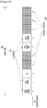
- FIG. 2 illustrates a method of multiplexing an N-UE and an L-UE in an LTE FDD system according to an embodiment of the present invention
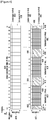
- FIG. 3 illustrates a method of multiplexing an N-UE and an L-UE in an LTE TDD system according to an embodiment of the present invention.
- a location of a subframe carrying an essential physical channel and Synchronization CHannel (SCH) as control information, a Physical Broadcast CHannel (PBCH), a paging message, and a System Information Block (SIB) is fixed.
- the SCH is carried in subframe#0 and subframe#5
- the PBCH is carried in subframe#0
- the paging message is carried in subframe#0, subframe#4, subframe#5, and subframe#9
- the SIB is carried in subframe#5.
- These subframes are referred to as Normal-subframes (N-subframes).
- the SCH includes a Primary Synchronization Sequence (PSS) and a Secondary Synchronization Sequence (SSS) as downlink physical channels for the UE to acquire radio frame timing synchronization and a cell IDentifier (ID).
- PSS Primary Synchronization Sequence
- SSS Secondary Synchronization Sequence
- ID cell IDentifier
- the SCH is mapped to 62 REs in the center frequency of the LTE system bandwidth.
- the PBCH provides a Master Information Block (MIB) carrying core information for a UE to access a system, such as DL system bandwidth, Physical HARQ Indicator CHannel (PHICH) resource information, and a System Frame Number (SFN).
- MIB Master Information Block
- PHICH Physical HARQ Indicator CHannel
- SFN System Frame Number
- the PBCH is mapped to 72 REs in the center frequency of the LTE system bandwidth in the frequency domain.
- the paging message is transmitted by an eNB in the downlink to notify the UE in an idle mode of an incoming call or a change of an SIB of the corresponding cell.
- the SIB is the control information required for the UE to access the system in addition to the MIB and includes cell-specific radio resource configuration information.
- the SIB is transmitted to the UE through Physical Downlink Shared Channel (PDSCH) as downlink physical data channel.
- PDSCH Physical Downlink Shared Channel
- subframe#0, subframe#4, subframe#5, and subframe#9 are N-subframes among the 10 total subframes of a radio frame 200, according to the FDD LTE standard.
- the L-UE receives the SCH and PBCH at least among the physical channels and control information in order to acquire radio frame timing synchronization, a cell ID, and an MIB.
- the eNB transmits a downlink control channel or a data channel for supporting the L-UE in subframes other than N-subframes in a radio frame. These subframes are referred to as potential L-subframes, and the L-subframe, which actually carries the control channel or data channel for supporting the L-UE is referred to as an L-subframe 230.
- L-subframe indicates the subframe designated for the second type terminal supporting a bandwidth narrower than the system bandwidth, but is not restricted to meaning a subframe for dedicated use by the second type terminal. That is, the L-subframe can be used for control or data channel transmission for the first type terminal too.
- subframe#1, subframe#2, subframe#3, subframe#6, subframe#7, and subframe#8 are the potential L-subframes.
- subframe#2 is configured as L-subframe. Further, although FIG. 2 is directed to a case where only one subframe is configured as an L-subframe, it is possible for one or more subframes to be configured as an L-subframe.
- the L-UE If the eNB transmits downlink data to the L-UE in subframe#2, the L-UE feeds back a HARQ ACK/NACK corresponding to the received downlink data.
- the L-UE transmits the HARQ ACK/NACK to the eNB, after a predetermined time, in consideration of the reception signal processing time for the downlink data.
- the L-UE transmits the HARQ ACK/NACK to the eNB in subframe#6, assuming that the signal processing time is 4 subframes.
- the subframe associated with the L-subframe 230 in HARQ timing relationship is referred to as an "associated L-subframe 240".
- the eNB uses 1 to 3 OFDM symbols at the beginning of the L-subframe 230 for transmitting control signal addressed to the N-UE and the rest for transmitting control or data channel for supporting the L-UE.
- the subframes of a radio frame are sorted into uplink and downlink subframes according to a TDD UL/DL configuration.
- Subframe#0, subframe#1, subframe#5, and subframe #6 are fixed as downlink subframes, regardless of the TDD UL/DL configuration, and subframe#2 is fixed as an uplink subframe.
- an SCH is transmitted in subframe#0, subframe#1, subframe#5, and subframe#6
- a PBCH is transmitted in subframe#0
- a paging message is transmitted in subframe#0, subframe#1, subframe#5, and subframe#6
- an SIB is transmitted in subframe#5.
- subframe#0, subframe#1, subframe#5, and subframe#6 of one radio frame 300 are N-subframes 310; and subframe#3, subframe#4, subframe#7, subframe#8, and subframe#9 are potential L-subframes 320.
- Subframe#3, subframe#4, subframe#7, subframe#8, and subframe#9 can be used as uplink or downlink subframes according to the TDD UL/DL configuration.
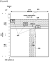
- FIG. 4 illustrates a time-frequency resource in respective N-subframe and L-subframe for multiplexing an N-UE and an L-UE in an LTE system according to an embodiment of the present invention.
- the system bandwidth is 5 MHz and includes 25 PRBs, i.e., PRB#0 to PRB#24.
- the N-UE is a broadband UE supporting a bandwidth of 5 MHz, which is equal to the system bandwidth
- the L-UE is the narrowband UE supporting a bandwidth of 1.4 MHz, which is narrower than the system bandwidth.
- the eNB divides the system bandwidth to secure one or more sub-bands for the L-UEs in the L-subframe. In FIG. 4 , three sub-bands, i.e., sub-band#1 402, sub-band#2 404, and sub-band#3 406, are used.
- Each sub-band has a bandwidth of 1.4 MHz and includes 6 PRBs such that the L-UE can support the sub-band.
- the L-UE operates in one of the sub-bands 402, 404, and 406.
- the sub-bands are spaced apart to minimize the interference to each other.
- Sub-band#1 402 is spaced apart from an edge of the system band as much as fdl,offset,edge 410 and from the sub-band#2 404 as much as fdl,offset, Inter 412.
- Sub-band#3 406 is spaced apart from the other edge of the system band as much as f dl,offset,edge 416 and from the sub-band#2 404 as much as f dl,offset,Inter 414.
- the offsets i.e., f dl,offset,edge 410, f dl,offset,Inter 412, f dl,offset,Inter 414, and f dl,offset,edge 416, and the bandwidth of each sub-band are signaled from the eNB to the UE or set to hardcoded values agreed between the eNB and the UE.
- the L-UE stops receiving data or control signal from the eNB while the N-UE receives data or control signal transmitted by the eNB.
- the eNB transmits the control signal addressed to the N-UE in N OFDM symbols 422 at the beginning of the N-subframe and transmits the data signal addressed to the N-UE in the rest symbols duration 424.
- the control signal includes the control information indicating the value of N, the control information for scheduling downlink or uplink data signal, and a HARQ ACK/NACK, and is distributively transmitted across the entire system band.
- the eNB transmits the control information for supporting the legacy N-UE in the N OFDM symbols duration 426 at the beginning of the L-subframe 420.
- the control information includes the control information indicating the value of N, the control information for scheduling an uplink data signal, and a HARQ ACK/NACK, and is distributively transmitted across the entire system band.
- the L-UE does not receive the control information or the data signal from the eNB during the N OFDM symbols duration 426 at the beginning of the L-subframe 420.
- the eNB transmits the control information or data for supporting the L-UE during the rest time duration of the sub-bands 428, 429, and 430, i.e., the time duration following the first N OFDM symbols region of the L-subframe.
- a certain L-UE operates in one of the sub-bands. For example, if the L-UE#1 operates on the sub-band#1 402, the eNB transmits the control information and data addressed to the L-UE#1 on the region 403 of the sub-band#1 402. If the L-UE#2 operates on the sub-band#2 404, the eNB transmits the control information and data addressed to the L-UE#2 on the region 429 of the sub-band#2 404.
- the eNB uses the resource corresponding to the region 432, 434, 436, and 438, other than the sub-band#1 402, sub-band#2 404, and sub-band#3 406 for data transmission to the legacy N-UE. Further, the eNB multiplexes the data addressed to the legacy N-UE and the data addressed to the L-UE into the resource regions 428, 429, and 430.
- Table 1 shows the sub-band sizes and number of sub-bands available for supporting L-UE per LTE system bandwidth. For example, the system bandwidth of 5 MHz can be divided to configure 1, 2, or 3 sub-bands of 1.4 MHz or 1 sub-band of 3 MHz.
- the method for configuring the control channel for supporting L-UE in the sub-band for the time duration of L-subframe can be implemented in various ways, e.g., FDM, TDM, or FDM/TDM.
- the control channel includes an L-PDCCH for scheduling the data for an L-UE and a Low-end Physical HARQ Indicator Channel (L-PHICH) for feedback of HARQ ACK/NACK corresponding to the uplink data of the L-UE.
- L-PHICH Low-end Physical HARQ Indicator Channel
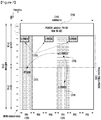
- FIG. 5 illustrates a sub-band having an L-PDCCH configured in an FDM mode in a subframe having a control region of two OFDM symbols at its beginning, according to an embodiment of the present invention.
- the sub-band 516 includes 6 PRBs 522, and the control channel 518 includes a PDCCH and a PHICH for the N-UE.
- the L-PDCCH 520 is mapped to a specific PRB 626 among the 6 PRBs according to the eNB's decision, in order to be transmitted over the time duration of the L-subframe 510, with the exception of the duration of the first two OFDM symbols.
- the L-PDCCH 520 provides the downlink scheduling control information corresponding to the Low-end Physical Downlink Shared CHannel (L-PDSCH) 522, which is mapped to the PRB 528 on the same sub-band in the same subframe, with the exception of the duration of its first two OFDM symbols.
- L-PDSCH Low-end Physical Downlink Shared CHannel
- the eNB determines the PRBs to which the L-PDCCH and the L-PDSCH are mapped among the PRBs of the sub-band based on the control information fed back by the L-UE.
- the L-PDCCH and L-PDSCH are mapped to one or more PRBs.
- the eNB selects the PRB having the best channel condition.
- the L-PDCCHs for different L-UEs are multiplexed in unit of PRB in the frequency domain (FDM).
- the L-PHICH 524 is mapped to the OFDM symbols following the one carrying the PDCCH or PHICH 518 for the N-UE as distributed in the time domain. Specifically, in FIG. 5 , the L-PHICH is mapped to the OFDM symbol#2 as distributed on a part of three PRBs. The number and location of the OFDM symbols to which the L-PHICH is mapped and the detailed mapping positions in the frequency domain may vary.
- FIG. 6 illustrates a sub-band having an L-PDCCH configured in a TDM mode in a subframe having a control region of two OFDM symbols at its beginning, according to an embodiment of the present invention.
- the control channel 618 of a PDCCH and/or a PHICH for an N-UE is mapped to two OFDM symbols at a beginning of an L-subframe 610, and the L-PDCCH and L-PHICH for an L-UE are mapped to the OFDM symbol#2, symbol#3, and symbol#4.
- the L-PDCCH 620 is distributively transmitted across the entire bandwidth of sub-band, and the L-PHICH 624 is segmented into small units in order to be distributed in the frequency and time domains.
- the L-PDCCHs for the L-UEs are interleaved and multiplexed onto the region of the OFDM symbol#2, symbol#3, and symbol#4 in the sub-band without being overlapped.
- the time duration for transmitting the L-PDCCH and L-PHICH can be determined based on a semi-static value signaled by the eNB through higher layer signaling or a value changing dynamically at every subframe through physical layer signaling.
- the L-PDSCH 622 is mapped to the frequency region indicated by the L-PDCCH after the time duration carrying the L-PDCCH on the same sub-band in the same subframe.
- FIG. 7 illustrates a sub-band having an L-PDCCH configured in an FDM/TDM mode in a subframe having a control region of two OFDM symbols at its beginning, according to an embodiment of the present invention.
- the sub-band 716 for L-UE includes 6 PRBs 730, and the control channel 718 of PDCCH and/or PHICH for an N-UE is transmitted in two OFDM symbols at a beginning of an L-subframe 710.
- the L-PDCCH 720 is mapped to a specific PRB 726 among the six PRBs according to the eNB's decision, in order to be transmitted for the time duration of slot#0 712 of the L-subframe, with the exception of the 2 OFDM symbols of control region.
- the L-PDSCH 724 which is scheduled by the L-PDCCH 720, is mapped to the same frequency region as the L-PDCCH 720 for the time duration of slot#1 714. Further, the L-PDCCH 720 can be configured for scheduling the L-PDSCH 722 mapped to other PRB 728. At this time, the L-PDSCH 722 is mapped to be transmitted for the entire duration of the L-subframe 710, with the exception of the control region carrying the PDCCH and/or the PHICH.
- the L-PDCCHs for different L-UEs are multiplexed in units of a PRB in the frequency domain (i.e., FDM) and multiplexed in units of a slot in the time domain (i.e., TDM).
- the L-PHICH 725 is mapped to the symbols following the control region 718 of the PDCCH and/or PHICH as distributed in the frequency domain. In FIG. 7 , the L-PHICH is mapped to the OFDM symbol#2 in the time domain and a part of each of three different PRBs in the frequency domain.
- the L-UE knows the control information on an L-subframe configuration and a sub-band configuration (hereinafter, referred to as an L-MIB) to receive L-PDCCH, L-PHICH, and L-PDSCH.
- the L-MIB is included in a PBCH along with the legacy MIB and broadcast by the eNB.
- the L-MIB is transmitted using the reserved bits of the legacy PBCH and follows the rule of channel coding, modulation, and time-frequency resource mapping specified in the LTE standard.
- the N-UE can acquire MIB from the PBCH without error in the LTE system.
- the L-UE receives the PBCH to acquire both the legacy MIB and L-MIB.
- the L-MIB includes the following control information:
- the L-MIB can be configured as shown below.
- there is no control information on the 'search space' such that the eNB is capable of transmitting L-PDCCH on a certain PRB in the 'DL subband bandwidth configuration'.
- the control information on the 'search space' can be notified to the UE through a separate L-SIB.
- L-MIB 'Subframe set index' , 'L-PHICH resource information' , 'DL subband bandwidth configuration'
- the L-MIB can be configured as shown below.
- the 'Subframe set index' and 'DL subband bandwidth configuration' can be signaled to the UE through a separate L-SIB or set to predetermined hardcoded values.
- L-MIB 'L-PHICH resource information' , 'Search space'
- the L-MIB may also be configured with only a 'DL subband bandwidth configuration.
- the 'Subframe set index', 'L-PHICH resource information', and 'Search space' can be signaled to the UE through a separate L-SIB or set to predetermined hardcoded values.
- L-MIB 'DL subband bandwidth configuration
- the L-MIB may also be configured with only 'L-PHICH resource information as shown below.
- the 'Subframe set index', 'DL subband bandwidth configuration', and 'Search space' can be signaled to the UE through a separate L-SIB or set to predetermined hardcoded values.
- L-MIB 'L-PHICH resource information'
- the L-MIB may also be configured with only the 'Subframe set index' as shown below.
- 'L-PHICH resource information', 'DL subband bandwidth configuration', and 'Search space' can be signaled to the UE through a separate L-SIB or set to predetermined hardcoded values.
- L-MIB 'Subframe set index'
- the L-MIB carries the information for receiving downlink control channels, i.e., an L-PDCCH, an L-PHICH, and an L-PDSCH, and the additional control information for supporting an L-UE, i.e., the downlink reception and the uplink transmission control information are configured in an L-SIB in order to be transmitted from the eNB to the UE through L-PDSCH.
- downlink control channels i.e., an L-PDCCH, an L-PHICH, and an L-PDSCH
- the additional control information for supporting an L-UE i.e., the downlink reception and the uplink transmission control information are configured in an L-SIB in order to be transmitted from the eNB to the UE through L-PDSCH.
- the L-SIB includes the following information:
- the eNB Prior to the UE operation, the eNB configures the detailed control informations included in the L-MIB and the L-SIB based on the information of the L-UEs to be supported in the LTE/LTE-A system, a number of L-UEs, and available resource amount.
- the eNB completes the configuration about the detained control informations before transmitting a PBCH and an L-PDCCH/L-PDSCH and reflects the configuration in transmitting the PBCH and the L-PDCCH/L-PDSCH.
- the eNB generates an L-MIB including the control information related to the L-subframe configuration and subband configuration, and transmits the L-MIB to the UE through the PBCH.
- the L-MIB may include at least one of a subframe configuration index, L-PHICH resource information, DL subband bandwidth configuration information, and a search space.
- the eNB generates an L-SIB including additional control information for supporting the L-UE, in addition to the L-MIB, and transmits the L-SIB to the UE through PDSCH scheduled by the L-PDCCH.
- the L-SIB may include at least one of a DL subband position, UL subband bandwidth configuration information, UL subband bandwidth configuration information, a UL subband position, PRACH configuration information, and physical channel configuration information.
- the eNB performs a random access procedure to accept the attach request of the UE.
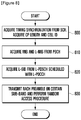
- FIG. 8 is a flowchart illustrating a UE procedure for receiving L-MIB and L-SIB and performing a random access procedure according to an embodiment of the present invention.
- the L-UE detects an SCH to access the system in step 800. Specifically, the L-UE acquires information, such as radio frame timing synchronization, a cell ID, and a Cyclic Prefix (CP) length from the SCH transmitted by an eNB.
- the SCH includes a Primary Synchronization Sequence (PSS) and a Secondary Synchronization Sequence (SSS) and is mapped to subframe#0 and subframe#5 to be transmitted.
- PSS Primary Synchronization Sequence
- SSS Secondary Synchronization Sequence
- the SCH is mapped to 62 REs in the center frequency of the LTE system band in the frequency domain.
- the L-UE receives a PBCH including an L-MIB dedicated to the L-UE, in addition to an MIB for an N-UE.
- the PBCH is mapped to subframe#0 to be transmitted.
- the PBCH is mapped to 72 REs in the center frequency of the LTE system bandwidth.
- the L-MIB may include at least one of a DL subband position, UL subband bandwidth configuration information, UL subband bandwidth configuration information, UL subband position, PRACH configuration information, and physical channel configuration information.
- the L-UE acquires L-SIB from the L-PDSCH.
- the L-SIB includes the control information for downlink reception and uplink transmission.
- the L-UE checks the position of the time-frequency resource to which the L-PDCCH is mapped based on the 'search space' information provided in the L-MIB or according to a predetermined rule.
- the L-UE extracts the L-PDCCH to receive the L-PDSCH indicated by the L-PDCCH and acquires an L-SIB from the L-PDSCH.
- the L-SIB may include at least one of a DL subband position, UL subband bandwidth configuration information, UL subband bandwidth configuration information, UL subband position, PRACH configuration information, and physical channel configuration information.
- the L-PDSCH including the L-SIB and the L-PDCCH for scheduling the L-PDSCH are transmitted on a predetermined subband among the downlink subbands for L-UE supported by the LTE system and in a predetermined subframe.
- the subband predetermined for transmitting the L-PDCCH includes the frequency region carrying the SCH and PBCH, such that the L-UE may receive an SCH, a PBCH, and an L-PDCCH, without changing a reception frequency band.
- the L-UE transmits the RACH preamble on a predetermined uplink subband (hereinafter, referred to as a first uplink subband). More specifically, the L-UE transmits the RACH preamble by referencing a RACH preamble sequence and subband, and subframe available for RACH preamble transmission extracted from the PRACH configuration included in the received L-SIB. Afterward, the L-UE receives a random access response from the eNB in response to the RACH preamble and performs RACH-related process.
- a predetermined uplink subband hereinafter, referred to as a first uplink subband. More specifically, the L-UE transmits the RACH preamble by referencing a RACH preamble sequence and subband, and subframe available for RACH preamble transmission extracted from the PRACH configuration included in the received L-SIB. Afterward, the L-UE receives a random access response from the eNB in response to the RACH preamble and performs RACH-related process.
- the L-UE is capable of transmitting the RACH preamble in two ways, i.e., method 1 and method 2.
- Method 1 restricts the first uplink subband to the subband corresponding to the downlink subband in step 820. That is, the first uplink subband is fixed as a certain subband in method 1.
- the one or more downlink subbands for an L-UE in the LTE system bandwidth has relationship with one or more uplink subbands for L-UE.
- the L-UE communicates with the eNB through the fixed subband during an initial random access procedure after receiving the SCH in order to minimize the transmission/reception complexity. If no random access response is received from the eNB and thus the initial random access procedure fails, the UE transmits the RACH preamble on an uplink subband (hereinafter, referred to second uplink subband), which is different from the first uplink subband, to resume the random access procedure. Consequently, the probability of a random access failure is reduced.
- second uplink subband which is different from the first uplink subband
- the L-UE transmits the initial RACH preamble without an uplink subband restriction. That is, the RACH preamble is initially transmitted by the L-UE on an uplink subband randomly selected from among the uplink subbands included in the LTE system bandwidth.
- Method 2 reduces overload caused by a concentration of the RACH preamble transmissions on a specific subband.
- the L-UE acquires the control information related to the RACH on each uplink subband in an L-MIB and an L-SIB transmitted by the eNB in order to perform random access a certain uplink subband.
- the eNB configures the RACH-related control information of the respective uplink subbands commonly or individually in adaptation to individual uplink subbands.
- the L-UE transitions to a Radio Resource Control (RRC) connected (RRC_CONNECTED) state to transmit and receive data in a unicast manner.
- RRC Radio Resource Control
- FIG. 9 illustrates a detailed time-frequency resource configuration of an uplink in an N-subframe and associated L-subframe in an LTE system supporting N-UE and L-UE multiplexing according to an embodiment of the present invention.
- the associated L-subframe is in a HARQ timing relationship with the downlink L-subframe and carries an uplink HARQ ACK/NACK and CQI feedback for an L-UE on an L-PUCCH and carries uplink data on an L-PUSCH.
- the PUCCH or PUSCH for an N-UE in the associated L-subframe can be transmitted without overlap with the L-PUCCH or the L-PUSCH for the L-UE in the frequency domain.
- the N-subframe carries a PUCCH or a PUSCH for an N-UE.
- the N-subframe is capable of carrying the L-PUSCH, but not the L-PUCCH, without overlap with the PUCCH or the PUSCH for the N-UE in the frequency domain.
- the system bandwidth is 5 MHz and includes 25 PRBs, i.e., PRB#0 to PRB#24.
- the N-UE is a wideband UE (i.e., a first type UE) supporting a bandwidth of 5 MHz, which is identical to the system bandwidth
- the L-UE is a narrow band UE (i.e., a second type UE) supporting a bandwidth of 1.4 MHz, which is narrower than the system bandwidth.
- the eNB is capable of dividing the system bandwidth to generate one or more sub-bands for an L-UE in an associated L-subframe.
- the system bandwidth is divided into three subbands, i.e., sub-band#1 902, sub-band#2 904, and sub-band#3 906.
- the bandwidth of each sub-band is 1.4 MHz, which the UE supports, and includes 6 PRBs.
- the L-UE operates on one of sub-band#1 902, sub-band#2 904, and sub-band#3 906 at a certain instance.
- the subbands are spaced apart by as much as a predetermined distance to avoid interfering with each other.
- the sub-band#1 902 is spaced apart from an edge of the system band by as much as f dl,offset,edge 910, and is spaced apart from the sub-band#2 904 by as much as fdl,offset, Inter 912.
- the sub-band#3 906 is spaced apart from the other edge of the system band by as much as fdl,offset,edge 916, and is spaced apart from the sub-band#2 904 by as much as f dl,offset,Inter 914.
- the offsets i.e., fdl,offset,edge 910, fdl,offset, Inter 912, fdl,offset, Inter 914, and fdl,offset,edge 916, and the bandwidth of each sub-band are signaled from the eNB to the UE or set to hardcoded values agreed between the eNB and the UE.
- reference numbers 922 and 924 denote frequency regions located at both edges of the system bandwidth for a PUCCH for an N-UE.
- the PUSCH and L-PUSCH can be multiplexed in the frequency region with the exception of the regions 922 and 924.
- the resource available to be allocated for L-PUSCH transmission is restricted to the sub-band predetermined for use of L-UE.
- reference numbers 926 and 928 denote the PRBs at both edges of the sub-band#1 902 that are configured for L-PUCCH transmission of the L-UE.
- reference number 926 or 828 corresponds to one PRB.
- reference numbers 930 and 932 denote the PRBs at both edges of the sub-band#2 904 that are configured for L-PUCCH transmission of the L-UE.
- reference numbers 934 and 936 denote the PRBs at both edges of the sub-band#3 906 that are configured for L-PUCCH transmission of the L-UE.
- the PUCCH transmission resources 922 and 924 of the N-UE have ful,offset,edge 910 and ful,offset,edge 916 wide enough to avoid overlapping with the L-PUCCH transmission resources 926 and 936 of the L-UE.
- the ful,offset,edge 910 and ful,offset,edge 916 can be defined as a distance between the uplink sub-band for the L-UE and the PUCCH resource region for the N-UE.
- the L-PUSCH transmitted by the L-UE in the associated L-subframe is restricted to the frequency region excluding the L-PUCCH transmission resource in the sub-band#1 902, sub-band#2 904, and sub-band#3 906.
- the UE transmits an SRS for the eNB to estimate uplink channel condition.
- the SRS is mapped to the last symbol of a predetermined uplink subframe and transmitted to the eNB on a predetermined frequency band.
- an L-SRS as the SRS transmitted by L-UE is mapped to the last symbol of a predetermined uplink subframe and transmitted to the eNB on a predetermined frequency band according to an embodiment of the present invention.
- FIG. 10 illustrates a sub-band configured for transmitting an L-SRS of an L-UE in an LTE system according to an embodiment of the present invention. Specifically, FIG. 10 illustrates a certain sub-band 1010 configured for use by the L-UE in an associated L-subframe 1000.
- the sub-band has a bandwidth of 1.4 MHz and includes 6 PRBs.
- Reference numbers 1020 and 1030 denote the PRBs at both edges of the sub-band 1010 as the frequency resource designated for L-PUCCH transmission of the L-UE.
- the L-UE When the associated L-subframe is configured for an L-SRS transmission, the L-UE multiplexes L-SRS in the last symbol 1040 of the associated L-subframe and transmits the L-SRS on a predetermined frequency band the sub-band for L-UE.
- the L-UE punctures the last symbol of L-PUCCH or L-PUSCH and multiplexes the L-PUCCH or L-PUSCH with the L-SRS.
- the L-UE acquires the control information about the L-subframe and frequency band for L-SRS transmission from the L-SIB.
- the L-SIB may also included the control information about the subframe and frequency band for SRS transmission of the N-UE.
- the L-UE punctures the last symbol of the L-PUSCH to multiplex the L-PUSCH and SRS in the N-subframe.
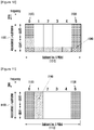
- FIG. 11 illustrates a sub-band configured for use by an L-UE in an associated L-subframe in an LTE system according to an embodiment of the present invention.
- the sub-band for L-UE has a bandwidth of 1.4 MHz and includes 6 PRBs.
- Reference numbers 1120 and 1130 denote the PRBs at both edges of the sub-band 1110 as the frequency resource designated for L-PUCCH transmission of the L-UE.
- the bandwidth of the RACH preamble is less than that corresponding to "bandwidth of sub-band for L-UE - number of PRBs allocated for L-PUCCH in sub-band for L-UE." Because the sub-band for an L-UE is relatively narrow, the smallest unit of frequency bandwidth of the RACH preamble is 1 PRB, and the bandwidth of the RACH preamble can be adjusted in units of 1 PRB.
- the RACH-related configuration information such as bandwidth and position of RACH preamble, sub-band, and subframe available for RACH preamble transmission, is transmitted from the eNB to the L-UE through an L-SIB.
- FIG. 12 is a block diagram illustrating an eNB according to an embodiment of the present invention.
- the eNB includes a controller 1208, an encoder 1210, a modulation mapper 1212, an RE mapper 1214, an OFDM signal generator 1216, and antenna 1218, and an information formatter 1220.
- the controller 1208 configures an L-subframe/N-subframe and a sub-band for an L-UE by referencing the numbers of L-UEs and N-UEs to be supported in the system and a resource amount available in the system and each sub-band.
- the controller 1208 controls the information formatter 1220 to generate control information or data to the L-UE.
- the controller 1208 controls the encoder 1210, the modulator 1212, and the RE mapper 1214 according to the channel coding scheme, modulation scheme, and time-frequency resource mapping scheme determined for the physical channel to be transmitted.
- the information formatter 1220 includes an MIB generator 1200, an L-MIB generator 1202, a Downlink Control Information (DCI) generator 1204, and a data generator 1206.
- the MIB generator 1200 formats the MIB including information on the DL system bandwidth, a PHICH resource, and an SFN, which are used by the UE to access the system, in the PBCH transmission format.
- the L-MIB generator 1202 generates an L-MIB including the control information related to the configuration of L-subframe and sub-band for L-UE.
- the L-MIB may include at least one of a subframe configuration index, L-PHICH resource information, DL sub-band bandwidth configuration information, and a search space.
- the L-MIB generator 1202 formats the control information in the PBCH transmission format.
- the formatted MIB and L-MIB are multiplexed into the PBCH, encoded by the encoder 1210 according to the channel coding scheme defined for PBCH, modulated by the modulator 1212, and mapped to time-frequency resource by the RE mapper 1214.
- the PBCH mapped to the time-frequency resource is processed by the OFDM signal generator 1216 and then transmitted to the UE through the antenna 1218.
- the DCI generator 1204 generates DCI for an N-UE or an L-UE in a PDCCH or an L-PDCCH transmission format.
- the formatted DCI is encoded by the encoder 1210 according to the channel coding scheme defined for the PDCCH or the L-PDCCH, modulated by the modulator 1212, and mapped to the time-frequency resource carrying the PDCCH or the L-PDCCH by the RE mapper 1214.
- the DCI is processed by the OFDM signal generator 1216 and then transmitted to the UE through then antenna 1218.
- the data generator 1206 generates the data addressed to the N-UE or the L-UE in the PDSCH or the L-PDCCH transmission format.
- the data addressed to the L-UE includes an L-SIB.
- the formatted data is encoded according to the channel coding scheme defined for the PDSCH or the L-PDSCH by the encoder 1210, modulated by the modulator 1212, and mapped to the time-frequency resource for transmitting PDSCH or L-PDSCH by the RE mapper 1214.
- the data are processed by the OFDM signal generator 1216 and then transmitted to the UE through the antenna 1218.
- FIG. 13 is a block diagram illustrating an L-UE according to an embodiment of the present invention.
- the L-UE includes an L-PUSCH generator 1300, an L-PUCCH generator 1302, a RACH preamble generator 1304, an L-SRS generator 1306, a controller 1308, an encoder 1310, a modulator 1312, a transform precoder 1314, an RE mapper 1316, an SC-FDMA signal generator 1318, and an antenna 1320.
- the controller 1308 of the L-UE controls transmission of uplink signals such as an L-PUSCH, an L-PUCCH, a RACH preamble, and an L-SRS based on control information such as an MIB, an L-MIB, and an L-SIB received from the eNB.
- the controller 1308 controls the encoder 1310, the modulator 1312, and the RE mapper 1316 according to the channel coding scheme, modulation scheme, and time-frequency resource mapping scheme defined for physical channels to be transmitted.
- the L-PUSCH generator 1300 If uplink scheduling information is received from the eNB, the L-PUSCH generator 1300 generates an L-PUSCH corresponding to the uplink scheduling information and the encoder 1310 encodes the L-PUSCH according to a channel coding scheme defined for the L-PUSCH.
- the modulator 1312 modulates the coded signal
- the transform precoder 1314 DFT-processes the modulated signal
- the RE mapper 1316 maps the process result to the time-frequency resource allocated for the L-PUSCH.
- the SC-FDMA signal generator 1318 processes the data, which is then transmitted to the eNB through the antenna 1320.
- the L-PUCCH generator 1302 configures the L-PUCCH, the encoder 1310 encodes the L-PUCCH according to the channel coding scheme defined for L-PUCCH, the modulator 1312 modulates the encoded signal, and the RE mapper 1316 maps the modulated signal to the time-frequency resource allocated for L-PUCCH transmission.
- the L-PUCCH is processed by the SC-FDMA signal generator 1318 and then transmitted to the eNB through the antenna 1320.
- the RACH preamble generator 1304 configures a RACH preambleand the RE mapper 1316 maps the RACH preamble to the time-frequency resource allocated for RACH preamble transmission.
- the RACH preamble is processed by the SC-FDMA signal generator 1318 and then transmitted to the eNB through the antenna 1320.
- the L-SRS generator 1306 In order to transmit an L-SRS, the L-SRS generator 1306 generates the L-SRS and the RE mapper 1316 maps the L-SRS to the time-frequency resource allocated for L-SRS transmission.
- the L-SRS is processed by the SC-FDMA signal generator 1318 and then transmitted to the eNB through the antenna 1320.
- the system access method of a narrowband UE according to the present invention is advantageous in that the narrowband UEs can be supported along wideband UEs in a wireless communication system.
Description
- The present invention relates generally to a cellular radio communication system and, in particular, to a system access method of a narrowband terminal in a cellular radio communication system supporting both wideband and narrowband terminals.
- Long Term Evolution (LTE) utilizes Orthogonal Frequency Division Multiplexing (OFDM) in a downlink and Single Carrier Frequency Division Multiple Access (SC-FDMA) in an uplink. Such a multiple access technique is characterized in that time-frequency resources carrying data or control information are arranged orthogonally to discriminate among per-user data and/or control information.
-
FIG. 1 illustrates a basic structure of time-frequency grid of radio resource for transmitting data and control channels in a downlink of a conventional LTE system. - In
FIG. 1 , the horizontal axis denotes time, and the vertical axis denotes frequency. An OFDM symbol is the smallest transmission unit on the time axis, aslot 106 includes NsymOFDM symbols 102, and asubframe 105 includes two slots. A slot is 0.5 ms, and a subframe is 1.0 ms. A subcarrier is the smallest transmission unit in the frequency domain, and the entire system transmission band includesNBW subcarriers 104. - In the time-frequency grid, a Resource Element (RE) 112 is the basic unit indicated by an OFDM symbol index and a subcarrier index. The Resource Block (RB) or Physical Resource Block (PHB) 108 includes the Nsymb consecutive OFDM symbols in the
time domain 102 and the NRB consecutive subcarriers in thefrequency domain 110. Accordingly, an RB 108 includes Nsymb x NRB REs. An RB is the smallest unit that can be scheduled for transmission. In an LTE system, Nsymb=7 and NRB=12, and NBW and NRB is in proportion to the system bandwidth. - The control information is transmitted in N OFDM symbols at the beginning of the subframe. Typically, N={1, 2, 3}. Accordingly, the amount of control information carried in a current subframe depends on the value of N. The control information includes an indicator that indicates the number of OFDM symbols carrying the control information, uplink and downlink scheduling information, Hybrid Automatic Repeat reQuest (HARQ)Acknowledgement (ACK)/Negative ACK (NACK) signal, Multiple Input Multiple Output (MIMO)-related control information, etc.
- The LTE system utilizes HARQ for retransmitting data that fails decoding in the physical layer. HARQ is a technique for ensuring reliability of data transmission in such a way that a receiver transmits a NACK to a transmitter to request a retransmission of the data that has failed decoding in the physical layer. The receiver combines the retransmitted data with the previously transmitted data to increase the data reception performance. If data is decoded successfully, the receiver transmits an ACK to the transmitter such that the transmitter can transmit next data.
- In a cellular radio communication system, scalable bandwidth is a significant feature for providing various types of data services. LTE supports scalable bandwidths of 1.4, 3, 5, 10, 15, and 20 MHz. These bandwidths correspond to 6, 15, 25, 50, 75, and 100 RBs, respectively. The mobile carriers use one of the available bandwidths to provided services. However, it is then necessary for the LTE system having a specific system bandwidth to support the terminals with different bandwidth capabilities.
- For example, an LTE system having a 10 MHz system bandwidth cannot simultaneously support a 10MHz terminal and a 1.4MHz terminal. Basically, the terminal supporting the bandwidth that is narrower than the system bandwidth cannot receive a downlink control channel that is transmitted across the entire system bandwidth in the LTE system.
- Also, terminals supporting different bandwidths may interfere with each other.
-
WO 2009/116751 A2 discloses a method of acquiring a resource allocation of a control channel, whcih includes acquiring a resource region of the control channel in a second subframe based on a first resource allocation of the control channel, acquiring a resource region of a second downlink channel in the second subframe based on the resource region of the control channel, and receiving a second resource allocation of the control channel on a third downlink channel in the second subframe. The third downlink channel is indicated by the second downlink channel. - "3rd Generation Partnership Project; Technical Specification Group Radio Access Network; Evolved Universal Terrestrial Radio Access (E-UTRA) and Evolved Universal Terrestrial Radio Access Network (E-UTRAN); Overall description; Stage 2 (Release 8)", 3GPP STANDARD ; TECHNICAL SPECIFICATION ; 3GPP TS 36.300, 3RD GENERATION PARTNERSHIP PROJECT (3GPP), MOBILE COMPETENCE CENTRE ; 650, ROUTE DES LUCIOLES ; F-06921 SOPHIA-ANTIPOLIS CEDEX ; FRANCE, vol. RAN WG2, no. V8.12.0, 20 April 2010 (2010-04-20), pages 1-149, XP051296843, provides an overview and overall description of the E-UTRAN radio interface protocol architecture.
-
US 2011/0211489 A1 discloses a communication method in a multi-carrier system, including: allocating radio resources for transmitting signals to a middle guard band; and transmitting the signals through the radio resources; wherein the middle guard band is a frequency band positioned between used bands of a plurality of carriers, respectively, within an aggregated carrier formed by aggregating the plurality of carriers and a unit allocating the radio resources of the middle guard band is different from a unit allocating the radio resources of the used bands. A multi-carrier system uses the guard bands between the carriers to improve channel estimation performance or increase efficiency of radio resources - The present invention has been made in an effort to solve the above problems and to provide at least the advantages described below.
- The solution to the problem is provided according to the independent claims. Embodiments are provided according to the dependent claims.
- The methods and apparatuses according to the present invention are advantageous in that a more efficient wireless communication system is achieved.
- The above and other aspects, features, and advantages of the present invention will be more apparent from the following detailed description taken in conjunction with the accompanying drawings, in which:
-
FIG. 1 illustrates a basic structure of a time-frequency grid of a radio resource for transmitting data and control channels in a downlink of a conventional LTE system; -
FIG. 2 illustrates a method of multiplexing a Normal-User Equipment (N-UE) and a Low-end UE (L-UE) in an LTE Frequency Division Duplexing (FDD) system according to an embodiment of the present invention; -
FIG. 3 illustrates a method of multiplexing an N-UE and an L-UE in an LTE Time Division Duplexing (TDD) system according to an embodiment of the present invention; -
FIG. 4 illustrates a time-frequency resource in respective N-subframe and L-subframe for multiplexing an N-UE and an L-UE in an LTE system according to an embodiment of the present invention; -
FIG. 5 illustrates a sub-band having an L-UE-specific Physical Downlink Control Channel (L-PDCCH) configured in a Frequency Division Multiplexing (FDM) mode in a subframe having a control region of two OFDM symbols at its beginning, according to an embodiment of the present invention; -
FIG. 6 illustrates a sub-band having an L-PDCCH configured in a Time Division Multiplexing (TDM) mode in a subframe having a control region of two OFDM symbols at its beginning, according to an embodiment of the present invention; -
FIG. 7 illustrates a sub-band having an L-PDCCH configured in an FDM/TDM mode in a subframe having a control region of two OFDM symbols at its beginning, according to an embodiment of the present invention; -
FIG. 8 is a flowchart illustrating a UE procedure for receiving L-MIB and L-SIB and performing a random access procedure according to an embodiment of the present invention; -
FIG. 9 illustrates a detailed time-frequency resource configuration of an uplink in an N-subframe and an associated L-subframe in an LTE system supporting N-UE and L-UE multiplexing, according to an embodiment of the present invention; -
FIG. 10 illustrates a sub-band configured for transmitting a Low-end Sounding Reference Signal (L-SRS) of an L-UE in an LTE system according to an embodiment of the present invention; -
FIG. 11 illustrates a sub-band configured for use by an L-UE in an associated L-subframe in an LTE system according to an embodiment of the present invention; -
FIG. 12 is a block diagram illustrating an evolved Node B (eNB) according to an embodiment of the present invention; and -
FIG. 13 is a block diagram illustrating an L-UE according to an embodiment of the present invention. - Various embodiments of the present invention are described in detail below with reference to the accompanying drawings. However, detailed descriptions of well-known functions and structures incorporated herein may be omitted to avoid obscuring the subject matter of the present invention.
- Terms used herein are defined by taking functions of the present invention into account and can be changed according to the practice or intention of users or operators. Therefore, definition of the terms should be made according to overall disclosures set forth herein.
- In the following description, a base station, i.e., a host, can be, for example, at least one of a Node B, an eNB, a radio access unit, a base station controller, or a specific node on the network. The terminal can be, for example, a UE, a Mobile Station (MS), a cellular phone, a smartphone, a computer, or a multimedia system equipped with communication function.
- Herein, the term "DownLink (DL)" denotes a transmission path of a radio signal from a base station to a terminal, and the term "UpLink (UL)" denotes a transmission of a radio signal from a terminal to a base station.
- Although embodiments of the present invention will be described below with reference to LTE and LTE-Advanced (LTE-A) systems, it will be understood by those skilled in the art that the present invention is also applicable to other communication systems having similar technical backgrounds and channel formats, with slight modifications, without departing from the scope of the present invention.
- For simplicity, a legacy wideband LTE terminal supporting a system bandwidth a mobile communication system is referred to herein as a "Normal UE (N-UE)". Also, the term "first type terminal supporting first type bandwidth" is interchangeably used with N-UE, under an assumption that the first type bandwidth is wider than a second type bandwidth, as will be described later.
- An LTE terminal supporting a narrower bandwidth than a system bandwidth is referred to as a "Low-end UE (L-UE)". Also, the term "second type terminal supporting the second byte bandwidth" is interchangeably used with L-UE, under the assumption that the second type bandwidth is narrower than the first type bandwidth.
- For example, the L-UE can be a low cost or low-end terminal supporting low data rate service such as voice communication and Machine Type Communication (MTC) or Machine-to-Machine (M2M) service, as compared to N-UE.
- In accordance with an embodiment of the present invention, a physical channel and control information of a legacy LTE system are reused as much as possible to support the L-UE while minimizing system design complexity. However, there are still problems to be addressed for simultaneously supporting both the N-UE and L-UE in the LTE system. For example, when the N-UE supporting wideband and the L-UE supporting narrowband coexist in the LTE system, the L-UE cannot receive a PDCCH designed for the legacy N-UE to receive across the entire system band. If an L-PDCCH is defined in a time-frequency resource for carrying the legacy PDCCH, the legacy N-UE has to know the location of the resource mapped to the L-PDCCH to receive the PDCCH addressed to the N-UE. In order to accomplish this, in accordance with an embodiment of the present invention, a method for time-division multiplexing the control channels addressed to the N-UE and L-UE is provided.
-
FIG. 2 illustrates a method of multiplexing an N-UE and an L-UE in an LTE FDD system according to an embodiment of the present invention, andFIG. 3 illustrates a method of multiplexing an N-UE and an L-UE in an LTE TDD system according to an embodiment of the present invention. - For an LTE downlink, a location of a subframe carrying an essential physical channel and Synchronization CHannel (SCH) as control information, a Physical Broadcast CHannel (PBCH), a paging message, and a System Information Block (SIB) is fixed. According to the LTE FDD specification, the SCH is carried in
subframe# 0 andsubframe# 5, the PBCH is carried insubframe# 0, the paging message is carried insubframe# 0,subframe# 4,subframe# 5, andsubframe# 9, and the SIB is carried insubframe# 5. These subframes are referred to as Normal-subframes (N-subframes). The SCH includes a Primary Synchronization Sequence (PSS) and a Secondary Synchronization Sequence (SSS) as downlink physical channels for the UE to acquire radio frame timing synchronization and a cell IDentifier (ID). The SCH is mapped to 62 REs in the center frequency of the LTE system bandwidth. - The PBCH provides a Master Information Block (MIB) carrying core information for a UE to access a system, such as DL system bandwidth, Physical HARQ Indicator CHannel (PHICH) resource information, and a System Frame Number (SFN). The PBCH is mapped to 72 REs in the center frequency of the LTE system bandwidth in the frequency domain.
- The paging message is transmitted by an eNB in the downlink to notify the UE in an idle mode of an incoming call or a change of an SIB of the corresponding cell. The SIB is the control information required for the UE to access the system in addition to the MIB and includes cell-specific radio resource configuration information. The SIB is transmitted to the UE through Physical Downlink Shared Channel (PDSCH) as downlink physical data channel.
- As illustrated in
FIG. 2 ,subframe# 0,subframe# 4,subframe# 5, andsubframe# 9 are N-subframes among the 10 total subframes of aradio frame 200, according to the FDD LTE standard. The L-UE according to an embodiment of the present invention receives the SCH and PBCH at least among the physical channels and control information in order to acquire radio frame timing synchronization, a cell ID, and an MIB. - The eNB transmits a downlink control channel or a data channel for supporting the L-UE in subframes other than N-subframes in a radio frame. These subframes are referred to as potential L-subframes, and the L-subframe, which actually carries the control channel or data channel for supporting the L-UE is referred to as an L-
subframe 230. The term "L-subframe" indicates the subframe designated for the second type terminal supporting a bandwidth narrower than the system bandwidth, but is not restricted to meaning a subframe for dedicated use by the second type terminal. That is, the L-subframe can be used for control or data channel transmission for the first type terminal too. - According to the FDD LTE standard,
subframe# 1,subframe# 2,subframe# 3,subframe# 6,subframe# 7, andsubframe# 8 are the potential L-subframes. - In
FIG. 2 ,subframe# 2 is configured as L-subframe. Further, althoughFIG. 2 is directed to a case where only one subframe is configured as an L-subframe, it is possible for one or more subframes to be configured as an L-subframe. - If the eNB transmits downlink data to the L-UE in
subframe# 2, the L-UE feeds back a HARQ ACK/NACK corresponding to the received downlink data. The L-UE transmits the HARQ ACK/NACK to the eNB, after a predetermined time, in consideration of the reception signal processing time for the downlink data. - In
FIG. 2 , the L-UE transmits the HARQ ACK/NACK to the eNB insubframe# 6, assuming that the signal processing time is 4 subframes. - In accordance with an embodiment of the present invention, the subframe associated with the L-
subframe 230 in HARQ timing relationship is referred to as an "associated L-subframe 240". The eNB uses 1 to 3 OFDM symbols at the beginning of the L-subframe 230 for transmitting control signal addressed to the N-UE and the rest for transmitting control or data channel for supporting the L-UE. - Referring to
FIG. 3 , in the LTE TDD standard, the subframes of a radio frame are sorted into uplink and downlink subframes according to a TDD UL/DL configuration.Subframe# 0,subframe# 1,subframe# 5, andsubframe # 6 are fixed as downlink subframes, regardless of the TDD UL/DL configuration, andsubframe# 2 is fixed as an uplink subframe. Among the downlink signals, an SCH is transmitted insubframe# 0,subframe# 1,subframe# 5, andsubframe# 6; a PBCH is transmitted insubframe# 0, a paging message is transmitted insubframe# 0,subframe# 1,subframe# 5, andsubframe# 6; and an SIB is transmitted insubframe# 5. - Accordingly, for LTE TDD,
subframe# 0,subframe# 1,subframe# 5, andsubframe# 6 of oneradio frame 300 are N-subframes 310; andsubframe# 3,subframe# 4,subframe# 7,subframe# 8, andsubframe# 9 are potential L-subframes 320.Subframe# 3,subframe# 4,subframe# 7,subframe# 8, andsubframe# 9 can be used as uplink or downlink subframes according to the TDD UL/DL configuration. -
FIG. 4 illustrates a time-frequency resource in respective N-subframe and L-subframe for multiplexing an N-UE and an L-UE in an LTE system according to an embodiment of the present invention. - Referring to
FIG. 4 , the system bandwidth is 5 MHz and includes 25 PRBs, i.e.,PRB# 0 toPRB# 24. The N-UE is a broadband UE supporting a bandwidth of 5 MHz, which is equal to the system bandwidth, and the L-UE is the narrowband UE supporting a bandwidth of 1.4 MHz, which is narrower than the system bandwidth. The eNB divides the system bandwidth to secure one or more sub-bands for the L-UEs in the L-subframe. InFIG. 4 , three sub-bands, i.e.,sub-band# 1 402,sub-band# 2 404, andsub-band# 3 406, are used. Each sub-band has a bandwidth of 1.4 MHz and includes 6 PRBs such that the L-UE can support the sub-band. The L-UE operates in one of the sub-bands 402, 404, and 406. The sub-bands are spaced apart to minimize the interference to each other.Sub-band# 1 402 is spaced apart from an edge of the system band as much as fdl,offset,edge 410 and from thesub-band# 2 404 as much as fdl,offset,Inter 412.Sub-band# 3 406 is spaced apart from the other edge of the system band as much asf dl,offset,edge 416 and from thesub-band# 2 404 as much asf dl,offset,Inter 414. The offsets, i.e.,f dl,offset,edge 410,f dl,offset,Inter 412,f dl,offset,Inter 414, andf dl,offset,edge 416, and the bandwidth of each sub-band are signaled from the eNB to the UE or set to hardcoded values agreed between the eNB and the UE. - During the N-
subframe 418, the L-UE stops receiving data or control signal from the eNB while the N-UE receives data or control signal transmitted by the eNB. The eNB transmits the control signal addressed to the N-UE inN OFDM symbols 422 at the beginning of the N-subframe and transmits the data signal addressed to the N-UE in therest symbols duration 424. The control signal includes the control information indicating the value of N, the control information for scheduling downlink or uplink data signal, and a HARQ ACK/NACK, and is distributively transmitted across the entire system band. The eNB transmits the control information for supporting the legacy N-UE in the NOFDM symbols duration 426 at the beginning of the L-subframe 420. The control information includes the control information indicating the value of N, the control information for scheduling an uplink data signal, and a HARQ ACK/NACK, and is distributively transmitted across the entire system band. The L-UE does not receive the control information or the data signal from the eNB during the NOFDM symbols duration 426 at the beginning of the L-subframe 420. - The eNB transmits the control information or data for supporting the L-UE during the rest time duration of the sub-bands 428, 429, and 430, i.e., the time duration following the first N OFDM symbols region of the L-subframe. In this case, a certain L-UE operates in one of the sub-bands. For example, if the L-
UE# 1 operates on thesub-band# 1 402, the eNB transmits the control information and data addressed to the L-UE# 1 on the region 403 of thesub-band# 1 402. If the L-UE# 2 operates on thesub-band# 2 404, the eNB transmits the control information and data addressed to the L-UE# 2 on theregion 429 of thesub-band# 2 404. - The eNB uses the resource corresponding to the
region sub-band# 1 402,sub-band# 2 404, andsub-band# 3 406 for data transmission to the legacy N-UE. Further, the eNB multiplexes the data addressed to the legacy N-UE and the data addressed to the L-UE into theresource regions [Table 1] System bandwidth [MHz] Combination of subbands (axb; a: subband bandwidth [MHz], b: number of subbands) 1.4 - 3 1.4x1, 1.4 x2 5 1.4x1, 1.4x2, 1.4 x3 3x1 10 1.4x1, 1.4x2, 1.4x3, 1.4x4, 1.4x5, 1.4x6, 1.4x7 3x1, 3x2, 3x3 5x1, 5x2 15 1.4x1, 1.4x2, 1.4x3, 1.4x4, 1.4x5, 1.4x6, 1.4x7, 1.4x8, 1.4x9, 1.4x10 3x1, 3x2, 3x3, 3x4, 3x5 5x1, 5x2, 5x3 20 1.4x1, 1.4x2, 1.4x3, 1.4x4, 1.4x5, 1.4x6, 1,4x7, 1.4x8, 1.4x9, 1.4x10, 1.4x11, 1.4x12, 1.4x13, 1.4x14 3x1, 3x2, 3x3, 3x4, 3x5, 3x6 5x1, 5x2, 5x3, 5x4 - The method for configuring the control channel for supporting L-UE in the sub-band for the time duration of L-subframe can be implemented in various ways, e.g., FDM, TDM, or FDM/TDM. The control channel includes an L-PDCCH for scheduling the data for an L-UE and a Low-end Physical HARQ Indicator Channel (L-PHICH) for feedback of HARQ ACK/NACK corresponding to the uplink data of the L-UE.
-
FIG. 5 illustrates a sub-band having an L-PDCCH configured in an FDM mode in a subframe having a control region of two OFDM symbols at its beginning, according to an embodiment of the present invention. - Referring to
FIG. 5 , the sub-band 516 includes 6PRBs 522, and thecontrol channel 518 includes a PDCCH and a PHICH for the N-UE. - The L-
PDCCH 520 is mapped to a specific PRB 626 among the 6 PRBs according to the eNB's decision, in order to be transmitted over the time duration of the L-subframe 510, with the exception of the duration of the first two OFDM symbols. The L-PDCCH 520 provides the downlink scheduling control information corresponding to the Low-end Physical Downlink Shared CHannel (L-PDSCH) 522, which is mapped to thePRB 528 on the same sub-band in the same subframe, with the exception of the duration of its first two OFDM symbols. The eNB determines the PRBs to which the L-PDCCH and the L-PDSCH are mapped among the PRBs of the sub-band based on the control information fed back by the L-UE. The L-PDCCH and L-PDSCH are mapped to one or more PRBs. Typically, the eNB selects the PRB having the best channel condition. The L-PDCCHs for different L-UEs are multiplexed in unit of PRB in the frequency domain (FDM). - The L-
PHICH 524 is mapped to the OFDM symbols following the one carrying the PDCCH orPHICH 518 for the N-UE as distributed in the time domain. Specifically, inFIG. 5 , the L-PHICH is mapped to theOFDM symbol# 2 as distributed on a part of three PRBs. The number and location of the OFDM symbols to which the L-PHICH is mapped and the detailed mapping positions in the frequency domain may vary. -
FIG. 6 illustrates a sub-band having an L-PDCCH configured in a TDM mode in a subframe having a control region of two OFDM symbols at its beginning, according to an embodiment of the present invention. - Referring to
FIG. 6 , thecontrol channel 618 of a PDCCH and/or a PHICH for an N-UE is mapped to two OFDM symbols at a beginning of an L-subframe 610, and the L-PDCCH and L-PHICH for an L-UE are mapped to theOFDM symbol# 2,symbol# 3, andsymbol# 4. The L-PDCCH 620 is distributively transmitted across the entire bandwidth of sub-band, and the L-PHICH 624 is segmented into small units in order to be distributed in the frequency and time domains. The L-PDCCHs for the L-UEs are interleaved and multiplexed onto the region of theOFDM symbol# 2,symbol# 3, andsymbol# 4 in the sub-band without being overlapped. - The time duration for transmitting the L-PDCCH and L-PHICH can be determined based on a semi-static value signaled by the eNB through higher layer signaling or a value changing dynamically at every subframe through physical layer signaling. The L-
PDSCH 622 is mapped to the frequency region indicated by the L-PDCCH after the time duration carrying the L-PDCCH on the same sub-band in the same subframe. -
FIG. 7 illustrates a sub-band having an L-PDCCH configured in an FDM/TDM mode in a subframe having a control region of two OFDM symbols at its beginning, according to an embodiment of the present invention. - Referring to
FIG. 7 , the sub-band 716 for L-UE includes 6PRBs 730, and thecontrol channel 718 of PDCCH and/or PHICH for an N-UE is transmitted in two OFDM symbols at a beginning of an L-subframe 710. The L-PDCCH 720 is mapped to aspecific PRB 726 among the six PRBs according to the eNB's decision, in order to be transmitted for the time duration ofslot# 0 712 of the L-subframe, with the exception of the 2 OFDM symbols of control region. - The L-
PDSCH 724, which is scheduled by the L-PDCCH 720, is mapped to the same frequency region as the L-PDCCH 720 for the time duration ofslot# 1 714. Further, the L-PDCCH 720 can be configured for scheduling the L-PDSCH 722 mapped toother PRB 728. At this time, the L-PDSCH 722 is mapped to be transmitted for the entire duration of the L-subframe 710, with the exception of the control region carrying the PDCCH and/or the PHICH. - The L-PDCCHs for different L-UEs are multiplexed in units of a PRB in the frequency domain (i.e., FDM) and multiplexed in units of a slot in the time domain (i.e., TDM). The L-
PHICH 725 is mapped to the symbols following thecontrol region 718 of the PDCCH and/or PHICH as distributed in the frequency domain. InFIG. 7 , the L-PHICH is mapped to theOFDM symbol# 2 in the time domain and a part of each of three different PRBs in the frequency domain. - The L-UE knows the control information on an L-subframe configuration and a sub-band configuration (hereinafter, referred to as an L-MIB) to receive L-PDCCH, L-PHICH, and L-PDSCH. The L-MIB is included in a PBCH along with the legacy MIB and broadcast by the eNB. The L-MIB is transmitted using the reserved bits of the legacy PBCH and follows the rule of channel coding, modulation, and time-frequency resource mapping specified in the LTE standard.
- Accordingly, the N-UE can acquire MIB from the PBCH without error in the LTE system. The L-UE receives the PBCH to acquire both the legacy MIB and L-MIB.
- The L-MIB includes the following control information:
- Subframe set index: an indicator that indicates the L-subframe, which is one of the subframes, excluding the subframes carrying an SCH, a PBCH, a paging message, and an SIB. In an LTE FDD system, it is possible to indicate the L-subframe in the form of a bitmap for
subframe# 1,subframe# 2,subframe# 3,subframe# 6,subframe# 7, andsubframe# 8. For example, ifsubframe# 1 andsubframe# 6 are configured as L-subframes, this can be indicated as [1, 0, 0, 1, 0, 0]. Here, bit positions of the bitmap correspond to therespective subframe# 1,subframe# 2,subframe# 3,subframe# 6,subframe# 7, andsubframe# 8; and the bit corresponding to subframe configured as L-subframe is indicated is set to 1 and others to 0. - L-PHICH resource information: indicates resource information of an L-PHICH and includes a number of OFDM symbols to which the L-PHICH is mapped or a resource amount in the time domain.
- DL sub-band bandwidth configuration: indicates size of the downlink sub-band for an L-UE supported in the LTE system. This is set to a value less than the downlink system bandwidth of the LTE system.
- Search space: indicates a PRB to which an L-PDCCH can be mapped in the downlink sub-band for an L-UE. The eNB selects at least one PRB within the configured search space and maps the L-PDCCH to be transmitted to each L-UE to the selected PRB. The L-MIB may include some or all of the control information. When all of the control information is included in the L-MIB, the L-MIB is configured as shown below, although the relative position of each control information can be changed.

- When a part of the control information is included, the L-MIB can be configured as shown below. In this case, there is no control information on the 'search space' such that the eNB is capable of transmitting L-PDCCH on a certain PRB in the 'DL subband bandwidth configuration'. The control information on the 'search space' can be notified to the UE through a separate L-SIB.

- Alternatively, when a part of the control information is included, the L-MIB can be configured as shown below. In this case, the 'Subframe set index' and 'DL subband bandwidth configuration' can be signaled to the UE through a separate L-SIB or set to predetermined hardcoded values.

- The L-MIB may also be configured with only a 'DL subband bandwidth configuration. In this case, the 'Subframe set index', 'L-PHICH resource information', and 'Search space' can be signaled to the UE through a separate L-SIB or set to predetermined hardcoded values.

- The L-MIB may also be configured with only 'L-PHICH resource information as shown below. In this case, the 'Subframe set index', 'DL subband bandwidth configuration', and 'Search space' can be signaled to the UE through a separate L-SIB or set to predetermined hardcoded values.

- The L-MIB may also be configured with only the 'Subframe set index' as shown below. In this case, 'L-PHICH resource information', 'DL subband bandwidth configuration', and 'Search space' can be signaled to the UE through a separate L-SIB or set to predetermined hardcoded values.

- The L-MIB carries the information for receiving downlink control channels, i.e., an L-PDCCH, an L-PHICH, and an L-PDSCH, and the additional control information for supporting an L-UE, i.e., the downlink reception and the uplink transmission control information are configured in an L-SIB in order to be transmitted from the eNB to the UE through L-PDSCH.
- The L-SIB includes the following information:
- DL subband position: indicates the positing in the frequency region of the downlink subband for an L-UE within the system bandwidth of the LTE system and expressed by the first PRB index of each subband or gap between subbands.
- UL subband bandwidth configuration: indicates the size of uplink subband for an L-UE within the uplink system bandwidth of the LTE system. This parameter is set to a value less than the uplink system bandwidth of the LTE system. When "UL subband bandwidth configuration" is associated with "DL subband bandwidth configuration," such that the two parameters have the same value or it is possible to acquire "UL subband bandwidth configuration" from "DL subband bandwidth configuration" included in the L-MIB according to a predetermined rule, the "UL subband bandwidth configuration" signaling can be omitted.
- UL subband position: indicates the position in the frequency region of the uplink subband for an L-UE in the system bandwidth of the LTE system and is expressed as the first PRB index of each subband or the gap between subbands. When "UL subband position" is associated with "DL subband position," such that the two parameters have the same value or it is possible to acquire "UL subband position" from "DL subband position" included in the L-SIB according to a predetermined rule, the "UL subband position" signaling can be omitted.
- PRACH configuration: is the RACH preamble sequence information used by the L-UE to perform random access and includes the information on the subband and subframe available for RACH preamble transmission.
- Physical Channel Configuration: includes the physical channel control information for the L-UE to transmit or receive an L-UE-specific Physical Uplink Control CHannel (L-PUCCH), an L-UE-specific Physical Uplink Shared CHannel (L-PUSCH), L-PDSCH, an L-UE-specific Channel Quality Indicator (L-CQI), L-SRS, etc. The L-PUCCH is the physical channel for the L-UE to transmit uplink HARQ ACK/NACK or the L-CQI and reuses the transmission structure of PUCCH of the legacy LTE system. The L-PUSCH is the physical channel for the L-UE to transmit uplink data and reuses the transmission structure of the PUSCH of the legacy LTE system. The L-PDSCH is the physical channel for the eNB to transmit downlink data to the L-UE and reuses the transmission structure of PDSCH of the legacy LTE system. The L-CQI is the control information fed back from the L-UE to the eNB for the purpose of link adaptation on the downlink physical channel and includes channel condition information and MIMO-related control information expressed by a Modulation and Coding Scheme (MCS). In order to transmit the L-CQI, the L-UE should know the control information, such as a transmission period of the L-CQI and a report type. The L-SRS is the SRS transmitted for the eNB to estimate the uplink channel condition. In order to transmit the L-SRS, the L-UE should know the control information, such as a frequency band and a subframe for the L-SRS transmission.
- Prior to the UE operation, the eNB configures the detailed control informations included in the L-MIB and the L-SIB based on the information of the L-UEs to be supported in the LTE/LTE-A system, a number of L-UEs, and available resource amount. The eNB completes the configuration about the detained control informations before transmitting a PBCH and an L-PDCCH/L-PDSCH and reflects the configuration in transmitting the PBCH and the L-PDCCH/L-PDSCH.
- More specifically, the eNB generates an L-MIB including the control information related to the L-subframe configuration and subband configuration, and transmits the L-MIB to the UE through the PBCH. The L-MIB may include at least one of a subframe configuration index, L-PHICH resource information, DL subband bandwidth configuration information, and a search space.
- The eNB generates an L-SIB including additional control information for supporting the L-UE, in addition to the L-MIB, and transmits the L-SIB to the UE through PDSCH scheduled by the L-PDCCH. The L-SIB may include at least one of a DL subband position, UL subband bandwidth configuration information, UL subband bandwidth configuration information, a UL subband position, PRACH configuration information, and physical channel configuration information.
- Afterward, if an attach request is received from a UE, the eNB performs a random access procedure to accept the attach request of the UE.
-
FIG. 8 is a flowchart illustrating a UE procedure for receiving L-MIB and L-SIB and performing a random access procedure according to an embodiment of the present invention. - Referring to
FIG. 8 , the L-UE detects an SCH to access the system instep 800. Specifically, the L-UE acquires information, such as radio frame timing synchronization, a cell ID, and a Cyclic Prefix (CP) length from the SCH transmitted by an eNB. The SCH includes a Primary Synchronization Sequence (PSS) and a Secondary Synchronization Sequence (SSS) and is mapped tosubframe# 0 andsubframe# 5 to be transmitted. The SCH is mapped to 62 REs in the center frequency of the LTE system band in the frequency domain. - In
step 810, the L-UE receives a PBCH including an L-MIB dedicated to the L-UE, in addition to an MIB for an N-UE. The PBCH is mapped tosubframe# 0 to be transmitted. The PBCH is mapped to 72 REs in the center frequency of the LTE system bandwidth. As described above, the L-MIB may include at least one of a DL subband position, UL subband bandwidth configuration information, UL subband bandwidth configuration information, UL subband position, PRACH configuration information, and physical channel configuration information. - In
step 820, the L-UE acquires L-SIB from the L-PDSCH. The L-SIB includes the control information for downlink reception and uplink transmission. The L-UE checks the position of the time-frequency resource to which the L-PDCCH is mapped based on the 'search space' information provided in the L-MIB or according to a predetermined rule. The L-UE extracts the L-PDCCH to receive the L-PDSCH indicated by the L-PDCCH and acquires an L-SIB from the L-PDSCH. - As described above, the L-SIB may include at least one of a DL subband position, UL subband bandwidth configuration information, UL subband bandwidth configuration information, UL subband position, PRACH configuration information, and physical channel configuration information. The L-PDSCH including the L-SIB and the L-PDCCH for scheduling the L-PDSCH are transmitted on a predetermined subband among the downlink subbands for L-UE supported by the LTE system and in a predetermined subframe.
- In accordance with an embodiment of the present invention, the subband predetermined for transmitting the L-PDCCH includes the frequency region carrying the SCH and PBCH, such that the L-UE may receive an SCH, a PBCH, and an L-PDCCH, without changing a reception frequency band.
- In
step 830, the L-UE transmits the RACH preamble on a predetermined uplink subband (hereinafter, referred to as a first uplink subband). More specifically, the L-UE transmits the RACH preamble by referencing a RACH preamble sequence and subband, and subframe available for RACH preamble transmission extracted from the PRACH configuration included in the received L-SIB. Afterward, the L-UE receives a random access response from the eNB in response to the RACH preamble and performs RACH-related process. - In accordance with an embodiment of the present invention, the L-UE is capable of transmitting the RACH preamble in two ways, i.e.,
method 1 andmethod 2. -
Method 1 restricts the first uplink subband to the subband corresponding to the downlink subband instep 820. That is, the first uplink subband is fixed as a certain subband inmethod 1. The one or more downlink subbands for an L-UE in the LTE system bandwidth has relationship with one or more uplink subbands for L-UE. - In
method 1, the L-UE communicates with the eNB through the fixed subband during an initial random access procedure after receiving the SCH in order to minimize the transmission/reception complexity. If no random access response is received from the eNB and thus the initial random access procedure fails, the UE transmits the RACH preamble on an uplink subband (hereinafter, referred to second uplink subband), which is different from the first uplink subband, to resume the random access procedure. Consequently, the probability of a random access failure is reduced. - Unlike
method 1, inmethod 2, the L-UE transmits the initial RACH preamble without an uplink subband restriction. That is, the RACH preamble is initially transmitted by the L-UE on an uplink subband randomly selected from among the uplink subbands included in the LTE system bandwidth.Method 2 reduces overload caused by a concentration of the RACH preamble transmissions on a specific subband. - In
method 2, the L-UE acquires the control information related to the RACH on each uplink subband in an L-MIB and an L-SIB transmitted by the eNB in order to perform random access a certain uplink subband. The eNB configures the RACH-related control information of the respective uplink subbands commonly or individually in adaptation to individual uplink subbands. - When the random access procedure completes successfully in
step 830, the L-UE transitions to a Radio Resource Control (RRC) connected (RRC_CONNECTED) state to transmit and receive data in a unicast manner. -
FIG. 9 illustrates a detailed time-frequency resource configuration of an uplink in an N-subframe and associated L-subframe in an LTE system supporting N-UE and L-UE multiplexing according to an embodiment of the present invention. - As described above, the associated L-subframe is in a HARQ timing relationship with the downlink L-subframe and carries an uplink HARQ ACK/NACK and CQI feedback for an L-UE on an L-PUCCH and carries uplink data on an L-PUSCH. In the associated L-subframe, the PUCCH or PUSCH for an N-UE in the associated L-subframe can be transmitted without overlap with the L-PUCCH or the L-PUSCH for the L-UE in the frequency domain. The N-subframe carries a PUCCH or a PUSCH for an N-UE. The N-subframe is capable of carrying the L-PUSCH, but not the L-PUCCH, without overlap with the PUCCH or the PUSCH for the N-UE in the frequency domain.
- In
FIG. 9 , the system bandwidth is 5 MHz and includes 25 PRBs, i.e.,PRB# 0 toPRB# 24. The N-UE is a wideband UE (i.e., a first type UE) supporting a bandwidth of 5 MHz, which is identical to the system bandwidth, and the L-UE is a narrow band UE (i.e., a second type UE) supporting a bandwidth of 1.4 MHz, which is narrower than the system bandwidth. - The eNB is capable of dividing the system bandwidth to generate one or more sub-bands for an L-UE in an associated L-subframe.
- In
FIG. 9 , the system bandwidth is divided into three subbands, i.e.,sub-band# 1 902,sub-band# 2 904, andsub-band# 3 906. The bandwidth of each sub-band is 1.4 MHz, which the UE supports, and includes 6 PRBs. The L-UE operates on one ofsub-band# 1 902,sub-band# 2 904, andsub-band# 3 906 at a certain instance. The subbands are spaced apart by as much as a predetermined distance to avoid interfering with each other. Thesub-band# 1 902 is spaced apart from an edge of the system band by as much asf dl,offset,edge 910, and is spaced apart from thesub-band# 2 904 by as much as fdl,offset,Inter 912. Thesub-band# 3 906 is spaced apart from the other edge of the system band by as much as fdl,offset,edge 916, and is spaced apart from thesub-band# 2 904 by as much asf dl,offset,Inter 914. The offsets, i.e., fdl,offset,edge 910, fdl,offset,Inter 912, fdl,offset,Inter 914, and fdl,offset,edge 916, and the bandwidth of each sub-band are signaled from the eNB to the UE or set to hardcoded values agreed between the eNB and the UE. - In
FIG. 9 ,reference numbers regions - In the associated L-subframe,
reference numbers sub-band# 1 902 that are configured for L-PUCCH transmission of the L-UE. - In
FIG. 9 ,reference number 926 or 828 corresponds to one PRB. Likewise,reference numbers sub-band# 2 904 that are configured for L-PUCCH transmission of the L-UE. Also,reference numbers sub-band# 3 906 that are configured for L-PUCCH transmission of the L-UE. - In the associated L-subframe, the
PUCCH transmission resources edge 910 and ful,offset,edge 916 wide enough to avoid overlapping with the L-PUCCH transmission resources edge 910 and ful,offset,edge 916 can be defined as a distance between the uplink sub-band for the L-UE and the PUCCH resource region for the N-UE. The L-PUSCH transmitted by the L-UE in the associated L-subframe is restricted to the frequency region excluding the L-PUCCH transmission resource in thesub-band# 1 902,sub-band# 2 904, andsub-band# 3 906. - In the LTE system, the UE transmits an SRS for the eNB to estimate uplink channel condition. The SRS is mapped to the last symbol of a predetermined uplink subframe and transmitted to the eNB on a predetermined frequency band. Likewise, an L-SRS as the SRS transmitted by L-UE is mapped to the last symbol of a predetermined uplink subframe and transmitted to the eNB on a predetermined frequency band according to an embodiment of the present invention.
-
FIG. 10 illustrates a sub-band configured for transmitting an L-SRS of an L-UE in an LTE system according to an embodiment of the present invention. Specifically,FIG. 10 illustrates acertain sub-band 1010 configured for use by the L-UE in an associated L-subframe 1000. - Referring to
FIG. 10 , the sub-band has a bandwidth of 1.4 MHz and includes 6 PRBs.Reference numbers last symbol 1040 of the associated L-subframe and transmits the L-SRS on a predetermined frequency band the sub-band for L-UE. When the L-PUCCH or L-PUSCH is transmitted with the L-SRS in the associated L-subframe, the L-UE punctures the last symbol of L-PUCCH or L-PUSCH and multiplexes the L-PUCCH or L-PUSCH with the L-SRS. - The L-UE acquires the control information about the L-subframe and frequency band for L-SRS transmission from the L-SIB. The L-SIB may also included the control information about the subframe and frequency band for SRS transmission of the N-UE.
- If the L-UE is scheduled by the eNB to transmit L-PUSCH in an N-subframe and if the N-subframe is configured for SRS transmission of the N-UE, the L-UE punctures the last symbol of the L-PUSCH to multiplex the L-PUSCH and SRS in the N-subframe.
-
FIG. 11 illustrates a sub-band configured for use by an L-UE in an associated L-subframe in an LTE system according to an embodiment of the present invention. - Referring to
FIG. 11 , the sub-band for L-UE has a bandwidth of 1.4 MHz and includes 6 PRBs.Reference numbers RACH preamble 1140, which is transmitted the L-UE to trigger a random access procedure, cannot be wider than the sub-band 1110 on which the L-UE operates. Accordingly, the bandwidth of the RACH preamble is less than that corresponding to "bandwidth of sub-band for L-UE - number of PRBs allocated for L-PUCCH in sub-band for L-UE." Because the sub-band for an L-UE is relatively narrow, the smallest unit of frequency bandwidth of the RACH preamble is 1 PRB, and the bandwidth of the RACH preamble can be adjusted in units of 1 PRB The RACH-related configuration information, such as bandwidth and position of RACH preamble, sub-band, and subframe available for RACH preamble transmission, is transmitted from the eNB to the L-UE through an L-SIB. -
FIG. 12 is a block diagram illustrating an eNB according to an embodiment of the present invention. - Referring to
FIG. 12 , the eNB includes acontroller 1208, anencoder 1210, amodulation mapper 1212, anRE mapper 1214, anOFDM signal generator 1216, andantenna 1218, and aninformation formatter 1220. - The
controller 1208 configures an L-subframe/N-subframe and a sub-band for an L-UE by referencing the numbers of L-UEs and N-UEs to be supported in the system and a resource amount available in the system and each sub-band. Thecontroller 1208 controls theinformation formatter 1220 to generate control information or data to the L-UE. Thecontroller 1208 controls theencoder 1210, themodulator 1212, and theRE mapper 1214 according to the channel coding scheme, modulation scheme, and time-frequency resource mapping scheme determined for the physical channel to be transmitted. - The
information formatter 1220 includes anMIB generator 1200, an L-MIB generator 1202, a Downlink Control Information (DCI)generator 1204, and adata generator 1206. TheMIB generator 1200 formats the MIB including information on the DL system bandwidth, a PHICH resource, and an SFN, which are used by the UE to access the system, in the PBCH transmission format. - The L-
MIB generator 1202 generates an L-MIB including the control information related to the configuration of L-subframe and sub-band for L-UE. The L-MIB may include at least one of a subframe configuration index, L-PHICH resource information, DL sub-band bandwidth configuration information, and a search space. The L-MIB generator 1202 formats the control information in the PBCH transmission format. The formatted MIB and L-MIB are multiplexed into the PBCH, encoded by theencoder 1210 according to the channel coding scheme defined for PBCH, modulated by themodulator 1212, and mapped to time-frequency resource by theRE mapper 1214. The PBCH mapped to the time-frequency resource is processed by theOFDM signal generator 1216 and then transmitted to the UE through theantenna 1218. - The
DCI generator 1204 generates DCI for an N-UE or an L-UE in a PDCCH or an L-PDCCH transmission format. The formatted DCI is encoded by theencoder 1210 according to the channel coding scheme defined for the PDCCH or the L-PDCCH, modulated by themodulator 1212, and mapped to the time-frequency resource carrying the PDCCH or the L-PDCCH by theRE mapper 1214. The DCI is processed by theOFDM signal generator 1216 and then transmitted to the UE through thenantenna 1218. - The
data generator 1206 generates the data addressed to the N-UE or the L-UE in the PDSCH or the L-PDCCH transmission format. The data addressed to the L-UE includes an L-SIB. The formatted data is encoded according to the channel coding scheme defined for the PDSCH or the L-PDSCH by theencoder 1210, modulated by themodulator 1212, and mapped to the time-frequency resource for transmitting PDSCH or L-PDSCH by theRE mapper 1214. The data are processed by theOFDM signal generator 1216 and then transmitted to the UE through theantenna 1218. -
FIG. 13 is a block diagram illustrating an L-UE according to an embodiment of the present invention. - Referring to
FIG. 13 , the L-UE includes an L-PUSCH generator 1300, an L-PUCCH generator 1302, aRACH preamble generator 1304, an L-SRS generator 1306, acontroller 1308, anencoder 1310, amodulator 1312, atransform precoder 1314, anRE mapper 1316, an SC-FDMA signal generator 1318, and anantenna 1320. - The
controller 1308 of the L-UE controls transmission of uplink signals such as an L-PUSCH, an L-PUCCH, a RACH preamble, and an L-SRS based on control information such as an MIB, an L-MIB, and an L-SIB received from the eNB. Thecontroller 1308 controls theencoder 1310, themodulator 1312, and theRE mapper 1316 according to the channel coding scheme, modulation scheme, and time-frequency resource mapping scheme defined for physical channels to be transmitted. - If uplink scheduling information is received from the eNB, the L-
PUSCH generator 1300 generates an L-PUSCH corresponding to the uplink scheduling information and theencoder 1310 encodes the L-PUSCH according to a channel coding scheme defined for the L-PUSCH. Themodulator 1312 modulates the coded signal, thetransform precoder 1314 DFT-processes the modulated signal, and theRE mapper 1316 maps the process result to the time-frequency resource allocated for the L-PUSCH. The SC-FDMA signal generator 1318 processes the data, which is then transmitted to the eNB through theantenna 1320. - In order to transmit an uplink HARQ ACK/NACK or an L-CQI, the L-
PUCCH generator 1302 configures the L-PUCCH, theencoder 1310 encodes the L-PUCCH according to the channel coding scheme defined for L-PUCCH, themodulator 1312 modulates the encoded signal, and theRE mapper 1316 maps the modulated signal to the time-frequency resource allocated for L-PUCCH transmission. The L-PUCCH is processed by the SC-FDMA signal generator 1318 and then transmitted to the eNB through theantenna 1320. - In order to perform random access, the
RACH preamble generator 1304 configures a RACH preambleand theRE mapper 1316 maps the RACH preamble to the time-frequency resource allocated for RACH preamble transmission. The RACH preamble is processed by the SC-FDMA signal generator 1318 and then transmitted to the eNB through theantenna 1320. - In order to transmit an L-SRS, the L-
SRS generator 1306 generates the L-SRS and theRE mapper 1316 maps the L-SRS to the time-frequency resource allocated for L-SRS transmission. The L-SRS is processed by the SC-FDMA signal generator 1318 and then transmitted to the eNB through theantenna 1320. - As described above, the system access method of a narrowband UE according to the present invention is advantageous in that the narrowband UEs can be supported along wideband UEs in a wireless communication system.
Claims (15)
- A method performed by a terminal in a wireless communication system, the method comprising:receiving, from a base station, a low-end master information block, L-MIB, including information associated with a search space of a low-end physical downlink control channel, L-PDCCH in a downlink sub-band through a physical broadcast channel, the information indicating a frequency resource for the search space of the L-PDCCH;identify the frequency resource for the search space of the L-PDCCH based on the information associated with the search space for the L-PDCCH;detecting downlink control information including scheduling information based on the frequency resource for the search space of the L-PDCCH; andreceiving, from the base station, system information through a first physical downlink shared channel, PDSCH, based on the scheduling information,wherein the system information includes information associated with a bandwidth of the downlink sub-band and a location of the downlink sub-band,wherein the system information further includes information associated with a bandwidth of an uplink sub-band and a location of the uplink sub-band, andwherein the system information is scheduled within a frequency range of the search space of the L-PDCCH.
- The method of claim 1, wherein the information associated with the search space of the L-PDCCH corresponds to at least one physical resource block, PRB, to which the L-PDCCH is to be mapped.
- The method of claim 1, wherein the system information includes information associated with a random access channel, RACH, configuration, and
wherein the location of the downlink sub-band and the location of the uplink sub-band correspond to a start resource block of the downlink sub-band and a start resource block of the uplink sub-band, respectively. - The method of claim 1,
wherein the L-PDCCH is transmitted on the frequency region which is a part of the downlink sub-band. - A terminal in a wireless communication system, the terminal comprising:a transceiver; anda controller configured to:receive, from a base station via the transceiver, a low-end master information block, L-MIB, including information associated with a search space of a low-end physical downlink control channel, L-PDCCH in a downlink sub-band through a physical broadcast channel, the information indicating a frequency resource for the search space of the L-PDCCH,identify the frequency resource for the search space of the L-PDCCH based on the information associated with the search space of the L-PDCCH,detect downlink control information including scheduling information based on the frequency resource for the search space of the L-PDCCH, andreceive, from the base station via the transceiver, system information through a first physical downlink shared channel, PDSCH, based on the scheduling information,wherein the system information includes information associated with a bandwidth of the downlink sub-band and a location of the downlink sub-band,wherein the system information further includes information associated with a bandwidth of an uplink sub-band and a location of the uplink sub-band, andwherein the system information is scheduled within a frequency range of the search space of the L-PDCCH.
- The terminal of claim 5, wherein the information associated with the search space of the L-PDCCH corresponds to at least one physical resource block, PRB, to which the L-PDCCH is to be mapped.
- The terminal of claim 5, wherein the system information includes information associated with a random access channel, RACH, configuration, and
wherein the location of the downlink sub-band and the location of the uplink sub-band correspond to a start resource block of the downlink sub-band and a start resource block of the uplink sub-band, respectively. - The terminal of claim 5,
wherein the L-PDCCH is transmitted on the frequency region which is a part of the downlink sub-band. - A method performed by a base station in a wireless communication system, the method comprising:transmitting a low-end master information block, L-MIB, including information associated with a search space of a low-end physical downlink control channel, L-PDCCH in a downlink sub-band through a physical broadcast channel, the information indicating a frequency resource for the search space of the L-PDCCH;transmitting downlink control information including scheduling information through the L-PDCCH based on the frequency resource for the search space of the L-PDCCH; andtransmitting system information through a first physical downlink shared channel, PDSCH, based on the scheduling information,wherein the system information includes information associated with a bandwidth of the downlink sub-band and a location of the downlink sub-band,wherein the system information further includes information associated with a bandwidth of an uplink sub-band and a location of the uplink sub-band, andwherein the system information is scheduled within a frequency range of the search space of the L-PDCCH.
- The method of claim 9, wherein the information associated with the search space of the L-PDCCH corresponds to at least one physical resource block, PRB, to which the L-PDCCH is to be mapped.
- The method of claim 9, wherein the system information includes information associated with a random access channel, RACH, configuration, and
wherein the location of the downlink sub-band and the location of the uplink sub-band correspond to a start resource block of the downlink sub-band and a start resource block of the uplink sub-band, respectively. - The method of claim 9, wherein the L-PDCCH is transmitted on the frequency region which is a part of the downlink sub-band.
- A base station in a wireless communication system, the base station comprising:a transceiver; anda controller configured to:transmit, via the transceiver, a low-end master information block, L-MIB, including information associated with a search space of a low-end physical downlink control channel, L-PDCCH in a downlink sub-band through a physical broadcast channel, the information indicating a frequency resource for the search space of the L-PDCCH,transmit downlink control information including scheduling information through the L-PDCCH based on the frequency resource for the search space of the L-PDCCH, andtransmit, via the transceiver, system information through a first physical downlink shared channel, PDSCH, based on the scheduling information,wherein the system information includes information associated with a bandwidth of the downlink sub-band and a location of the downlink sub-band,wherein the system information further includes information associated with a bandwidth of an uplink sub-band and a location of the uplink sub-band, andwherein the system information is scheduled within a frequency range of the search space of the L-PDCCH.
- The base station of claim 13, wherein the information associated with the search space of the L-PDCCH corresponds to at least one physical resource block, PRB, to which the L-PDCCH is to be mapped.
- The base station of claim 13,
wherein the resource for the L-PDCCH corresponds to a search space of the L-PDCCH,
wherein the location of the downlink sub-band and the location of the uplink sub-band correspond to a start resource block of the downlink sub-band and a start resource block of the uplink sub-band, respectively.
wherein the system information includes information associated with a random access channel, RACH, configuration, and
wherein the L-PDCCH is transmitted on the frequency region which is a part of the downlink sub-band.
Priority Applications (2)
| Application Number | Priority Date | Filing Date | Title |
|---|---|---|---|
| PL18207368T PL3462799T3 (en) | 2011-09-23 | 2012-09-24 | Methods and apparatuses in a wireless communication system |
| EP21189498.5A EP3927084B1 (en) | 2011-09-23 | 2012-09-24 | System access method and apparatus of a narrowband terminal in a wireless communication system supporting wideband and narrowband terminals |
Applications Claiming Priority (3)
| Application Number | Priority Date | Filing Date | Title |
|---|---|---|---|
| KR1020110096206A KR101962245B1 (en) | 2011-09-23 | 2011-09-23 | Method and apparatus for accessing of narrowband terminal to a wireless communication system supporting both wideband terminal and narrowband terminal |
| PCT/KR2012/007634 WO2013043006A1 (en) | 2011-09-23 | 2012-09-24 | System access method and apparatus of a narrowband terminal in a wireless communication system supporting wideband and narrowband terminals |
| EP12834323.3A EP2759076B1 (en) | 2011-09-23 | 2012-09-24 | System access method and apparatus of a narrowband terminal in a wireless communication system supporting wideband and narrowband terminals |
Related Parent Applications (1)
| Application Number | Title | Priority Date | Filing Date |
|---|---|---|---|
| EP12834323.3A Division EP2759076B1 (en) | 2011-09-23 | 2012-09-24 | System access method and apparatus of a narrowband terminal in a wireless communication system supporting wideband and narrowband terminals |
Related Child Applications (1)
| Application Number | Title | Priority Date | Filing Date |
|---|---|---|---|
| EP21189498.5A Division EP3927084B1 (en) | 2011-09-23 | 2012-09-24 | System access method and apparatus of a narrowband terminal in a wireless communication system supporting wideband and narrowband terminals |
Publications (2)
| Publication Number | Publication Date |
|---|---|
| EP3462799A1 EP3462799A1 (en) | 2019-04-03 |
| EP3462799B1 true EP3462799B1 (en) | 2021-08-04 |
Family
ID=47911243
Family Applications (3)
| Application Number | Title | Priority Date | Filing Date |
|---|---|---|---|
| EP12834323.3A Active EP2759076B1 (en) | 2011-09-23 | 2012-09-24 | System access method and apparatus of a narrowband terminal in a wireless communication system supporting wideband and narrowband terminals |
| EP18207368.4A Active EP3462799B1 (en) | 2011-09-23 | 2012-09-24 | Methods and apparatuses in a wireless communication system |
| EP21189498.5A Active EP3927084B1 (en) | 2011-09-23 | 2012-09-24 | System access method and apparatus of a narrowband terminal in a wireless communication system supporting wideband and narrowband terminals |
Family Applications Before (1)
| Application Number | Title | Priority Date | Filing Date |
|---|---|---|---|
| EP12834323.3A Active EP2759076B1 (en) | 2011-09-23 | 2012-09-24 | System access method and apparatus of a narrowband terminal in a wireless communication system supporting wideband and narrowband terminals |
Family Applications After (1)
| Application Number | Title | Priority Date | Filing Date |
|---|---|---|---|
| EP21189498.5A Active EP3927084B1 (en) | 2011-09-23 | 2012-09-24 | System access method and apparatus of a narrowband terminal in a wireless communication system supporting wideband and narrowband terminals |
Country Status (8)
| Country | Link |
|---|---|
| US (6) | US9031019B2 (en) |
| EP (3) | EP2759076B1 (en) |
| KR (1) | KR101962245B1 (en) |
| ES (2) | ES2702538T3 (en) |
| FI (1) | FI3927084T3 (en) |
| HU (1) | HUE056088T2 (en) |
| PL (1) | PL3462799T3 (en) |
| WO (1) | WO2013043006A1 (en) |
Families Citing this family (101)
| Publication number | Priority date | Publication date | Assignee | Title |
|---|---|---|---|---|
| KR101962245B1 (en) * | 2011-09-23 | 2019-03-27 | 삼성전자 주식회사 | Method and apparatus for accessing of narrowband terminal to a wireless communication system supporting both wideband terminal and narrowband terminal |
| CN103918340B9 (en) * | 2012-11-02 | 2018-03-23 | 华为技术有限公司 | Method for determining channel loss, base station and user equipment |
| CN103906139B (en) * | 2012-12-27 | 2018-10-30 | 夏普株式会社 | The method of sending and receiving of system information and base station and user equipment |
| CN104798400B (en) * | 2013-01-09 | 2019-07-19 | Lg 电子株式会社 | Receive the method for signal and the method and base station of user equipment and transmission signal |
| EP2787678B1 (en) * | 2013-04-02 | 2016-11-02 | Industrial Technology Research Institute | Master information block, mib, mapping in lte symstems using a new carrier type physical broadcast channel |
| US9445378B2 (en) * | 2013-07-25 | 2016-09-13 | Lg Electronics Inc. | Method and apparatus for coverage enhancement |
| WO2015024265A1 (en) * | 2013-08-23 | 2015-02-26 | 华为技术有限公司 | Method for transmitting information and method, apparatus and system for determining information in tdd system |
| US9775134B2 (en) * | 2013-09-20 | 2017-09-26 | Samsung Electronics Co., Ltd. | System and method for coverage enhancements of broadcast channels |
| US9949216B2 (en) | 2013-09-25 | 2018-04-17 | Apple Inc. | Power consumption optimization for cellular communication via power amplifier biasing |
| US9622184B2 (en) * | 2013-09-25 | 2017-04-11 | Apple Inc. | Transport block size and channel condition assessment based power consumption reduction for cellular communication |
| US9820247B2 (en) * | 2014-07-30 | 2017-11-14 | Intel IP Corporation | Enhanced node B (ENB) and method for MTC coexistence |
| US9769817B2 (en) * | 2014-08-06 | 2017-09-19 | Qualcomm Incorporated | Linked narrowband operation for MTC |
| AU2015301498B2 (en) * | 2014-08-15 | 2019-12-12 | Interdigital Patent Holdings, Inc. | Method and apparatus for supporting uplink transmission and MBMS for a WTRU with reduced bandwidth |
| US10412664B2 (en) * | 2014-09-18 | 2019-09-10 | Lg Electronics Inc. | Method and apparatus for configuring bandwidth including direct current subcarrier for low cost user equipment in wireless communication system |
| WO2016043565A1 (en) * | 2014-09-19 | 2016-03-24 | 엘지전자 주식회사 | Method for obtaining downlink synchronization, and mtc apparatus |
| WO2016048027A2 (en) * | 2014-09-23 | 2016-03-31 | 엘지전자 주식회사 | Method and user equipment for receiving downlink signal, and method and base station for transmitting downlink signal |
| CN105451155B (en) * | 2014-09-26 | 2020-10-27 | 中兴通讯股份有限公司 | Channel and signal transmission method, corresponding terminal and base station |
| WO2016053047A1 (en) * | 2014-10-02 | 2016-04-07 | 엘지전자 주식회사 | Method and user equipment for transmitting uplink signal, and method and user equipment for receiving uplink signal |
| US9374796B2 (en) * | 2014-10-10 | 2016-06-21 | Qualcomm Incorporated | Channel structure for a cellular internet of things system |
| US10027462B2 (en) * | 2014-10-31 | 2018-07-17 | Qualcomm Incorporated | Unified frame structure |
| US9762324B2 (en) * | 2014-10-31 | 2017-09-12 | Futurewei Technologies, Inc. | Channel mapping for an aggregated touchless wireless fronthaul |
| WO2016108503A1 (en) * | 2014-12-30 | 2016-07-07 | 엘지전자 주식회사 | Method and device for obtaining system information in wireless communication system |
| CN112118216A (en) * | 2015-01-16 | 2020-12-22 | 三星电子株式会社 | Control information transmission method and apparatus in wireless communication system |
| CN105992356B (en) * | 2015-02-05 | 2019-04-09 | 上海诺基亚贝尔股份有限公司 | The method and apparatus of allocated subbands in communication system based on machine-type communication |
| US10098123B2 (en) | 2015-02-11 | 2018-10-09 | Qualcomm Incorporated | Service type indicator in master information block (MIB) |
| US10326568B2 (en) * | 2015-02-12 | 2019-06-18 | Lg Electronics Inc. | Method and apparatus for supporting frequency hopping for low cost user equipment in wireless communication system |
| US10681676B2 (en) * | 2015-02-25 | 2020-06-09 | Qualcomm Incorporated | Narrowband management for machine type communications |
| US9887801B2 (en) | 2015-03-11 | 2018-02-06 | Samsung Electronics Co., Ltd. | Resource allocation for repetitions of transmissions in a communication system |
| US9860030B2 (en) * | 2015-03-26 | 2018-01-02 | Samsung Electronics Co., Ltd. | Transmission of system information for low cost user equipment |
| WO2016159680A1 (en) * | 2015-04-02 | 2016-10-06 | 오혁준 | Machine-to-machine communication method for extending coverage, and apparatus and system for performing same |
| US9510134B2 (en) | 2015-04-02 | 2016-11-29 | Hyunyong Song | Method for performing machine type communication for the purpose of coverage improvement, apparatuses and systems for performing the same |
| EP3079410B1 (en) * | 2015-04-10 | 2018-06-06 | Alcatel Lucent | Transmitting control information to low complexity user equipment |
| US10693602B2 (en) | 2015-05-29 | 2020-06-23 | Futurewei Technologies, Inc. | System and method for a long-term evolution (LTE)-compatible subframe structure for wideband LTE |
| EP3294033B1 (en) | 2015-06-01 | 2020-01-15 | Huawei Technologies Co., Ltd. | Resource scheduling method and apparatus |
| US10582441B2 (en) | 2015-06-11 | 2020-03-03 | Lg Electronics Inc. | Method and apparatus for transmitting system information for cellular internet-of-things in wireless communication system |
| WO2016200229A1 (en) * | 2015-06-11 | 2016-12-15 | Lg Electronics Inc. | Method and apparatus for supporting time division duplex for celluar internet-of-things in wireless communication system |
| CN113115406A (en) * | 2015-06-11 | 2021-07-13 | 苹果公司 | Low overhead system information acquisition for wireless communication |
| KR102262300B1 (en) | 2015-06-17 | 2021-06-08 | 삼성전자 주식회사 | Method and apparatus for signal transmission using narrow band in wirelss cellular communication system |
| WO2016208897A1 (en) | 2015-06-22 | 2016-12-29 | 엘지전자 주식회사 | Method for transmitting uplink channel and nb-iot device |
| US11025376B2 (en) | 2015-06-25 | 2021-06-01 | Apple Inc. | Dynamic partition resource allocation in 5G networks |
| KR102596103B1 (en) | 2015-07-22 | 2023-10-31 | 삼성전자 주식회사 | Method and apparatus for operating machine Type communications in wireless communication system |
| KR102616547B1 (en) * | 2015-07-23 | 2023-12-26 | 삼성전자 주식회사 | Method and apparatus for narrowband signal transmission in a wireless cellular communication system |
| JP6076424B1 (en) * | 2015-08-13 | 2017-02-08 | 株式会社Nttドコモ | User terminal, radio base station, and radio communication method |
| US10601627B2 (en) | 2015-09-02 | 2020-03-24 | Lg Electronics Inc. | Method and apparatus for indicating center frequency offset for narrowband UE in wireless communication system |
| CN106488509B (en) | 2015-09-02 | 2021-10-19 | 中兴通讯股份有限公司 | System message transmission method and device |
| WO2017036385A1 (en) * | 2015-09-02 | 2017-03-09 | 中兴通讯股份有限公司 | System message transmission method and device |
| CN106507367B (en) * | 2015-09-06 | 2019-04-16 | 中兴通讯股份有限公司 | A kind of transmission method and device of narrowband orthogonal frequency-division multiplex singal |
| US11212760B2 (en) * | 2015-09-24 | 2021-12-28 | Qualcomm Incorporated | Common synchronization channel design for narrowband communications |
| WO2017058288A1 (en) * | 2015-09-28 | 2017-04-06 | Intel IP Corporation | Air interface resource utilization techniques for wireless communication networks |
| CN108352934B (en) * | 2015-11-06 | 2021-01-12 | 华为技术有限公司 | Method and base station for transmitting downlink data |
| WO2017111517A1 (en) * | 2015-12-22 | 2017-06-29 | Samsung Electronics Co., Ltd. | Method and apparatus for operating narrow bandwidth communications in wireless communication system |
| CN106961315B (en) | 2016-01-11 | 2020-03-17 | 电信科学技术研究院 | Narrowband PBCH transmission method and device |
| US11540320B2 (en) * | 2016-01-15 | 2022-12-27 | Ntt Docomo, Inc. | User terminal, radio base station and radio communication method |
| WO2017131806A1 (en) * | 2016-01-27 | 2017-08-03 | Intel IP Corporation | Reference signals and physical broadcast channel for 5g systems |
| EP4187832A1 (en) * | 2016-01-29 | 2023-05-31 | Ntt Docomo, Inc. | User terminal, radio base station and radio communication method |
| US10477537B2 (en) * | 2016-02-11 | 2019-11-12 | Qualcomm Incorporated | Multi-PRB operation for narrowband systems |
| US11319107B2 (en) * | 2016-03-07 | 2022-05-03 | Qualcomm Incorporated | Synchronization for standalone LTE broadcast |
| WO2017155324A1 (en) * | 2016-03-10 | 2017-09-14 | 엘지전자 주식회사 | Method for performing random access procedure for single tone transmission in wireless communication system and apparatus therefor |
| KR102301825B1 (en) * | 2016-03-14 | 2021-09-14 | 삼성전자 주식회사 | Method and apparatus for synchronization operation in a cellular Internet of Things network |
| US10389501B2 (en) * | 2016-03-16 | 2019-08-20 | Lg Electronics Inc. | Method and apparatus for utilizing 5G spectrum and frame structure in wireless communication system |
| WO2017179859A1 (en) * | 2016-04-10 | 2017-10-19 | 엘지전자 주식회사 | Method and device for transmitting uplink reference signal in wireless communication system |
| US11076433B2 (en) * | 2016-04-14 | 2021-07-27 | Lg Electronics Inc. | Dynamic subband-based signal transceiving method and apparatus therefor in wireless communication system |
| CN112235225B (en) * | 2016-05-09 | 2024-04-12 | 三星电子株式会社 | Method and apparatus for transmitting/receiving synchronization signal in wireless cellular communication system |
| US10536314B2 (en) * | 2016-06-03 | 2020-01-14 | Centre Of Excellence In Wireless Technology | OFDMA apparatus and method thereof for performing OFDM based communication in wireless communication system |
| TWI620461B (en) * | 2016-06-17 | 2018-04-01 | 財團法人資訊工業策進會 | Narrowband internet of things system and preamble transmission method thereof |
| CN115426085A (en) | 2016-07-25 | 2022-12-02 | 北京三星通信技术研究有限公司 | Method and equipment for receiving public signaling |
| CN107659963B (en) * | 2016-07-26 | 2020-12-04 | 华为技术有限公司 | Configuration method of leader sequence, user equipment and access network equipment |
| CN106850165B (en) * | 2016-07-29 | 2019-03-05 | 展讯通信(上海)有限公司 | The indicating means and device of subband arrangement, subband cut-in method and device |
| US10986609B2 (en) * | 2016-08-03 | 2021-04-20 | Lenovo Innovations Limited (Hong Kong) | Device-to-device transmission |
| GB2552689A (en) | 2016-08-03 | 2018-02-07 | Nec Corp | Communication system |
| CN110545570B (en) * | 2016-08-09 | 2020-07-21 | 华为技术有限公司 | System message sending method and equipment |
| US10517074B2 (en) * | 2016-08-11 | 2019-12-24 | Kt Corporation | Methods for allocating data channel resources in a wireless communication system and apparatuses |
| WO2018056696A1 (en) * | 2016-09-20 | 2018-03-29 | 엘지전자(주) | Method for transmitting/receiving data in wireless communication system and device therefor |
| CN107889156B (en) * | 2016-09-30 | 2022-10-11 | 中兴通讯股份有限公司 | Method and device for sending and receiving access information and transmission system |
| US10433342B2 (en) * | 2016-10-19 | 2019-10-01 | Qualcomm Incorporated | Enhanced random access channel (RACH) procedure |
| US11770855B2 (en) | 2016-10-19 | 2023-09-26 | Qualcomm Incorporated | Random access channel (RACH) procedure design |
| CN106788881B (en) * | 2016-11-04 | 2019-06-07 | 北京展讯高科通信技术有限公司 | Dispatching method, device and the base station of nonessential system message |
| JP7173963B2 (en) | 2016-11-09 | 2022-11-16 | エルジー エレクトロニクス インコーポレイティド | Synchronization signal transmission method and device therefor |
| CN108112022B (en) * | 2016-11-24 | 2020-02-21 | 维沃移动通信有限公司 | System information block transmission method, terminal and network side equipment |
| CN108633055B (en) * | 2017-03-24 | 2022-02-25 | 华为技术有限公司 | Information transmission method and communication equipment |
| CN108738134A (en) * | 2017-04-13 | 2018-11-02 | 普天信息技术有限公司 | A kind of time division multiplexing random access resource selection method |
| CN108811173B (en) * | 2017-05-05 | 2021-09-03 | 北京三星通信技术研究有限公司 | Random access method, base station equipment and user equipment |
| EP4250814A3 (en) | 2017-06-16 | 2023-11-01 | Electronics and Telecommunications Research Institute | Method for configuring bandwidth for supporting broadband carrier in communication system |
| CN109565830B (en) | 2017-06-16 | 2023-01-06 | Lg 电子株式会社 | Method for transceiving downlink channel and apparatus therefor |
| US11212761B2 (en) | 2017-07-04 | 2021-12-28 | Samsung Electronics Co., Ltd. | Method and apparatus for communication based on frame structure |
| CN109309556B (en) | 2017-07-27 | 2022-03-29 | 夏普株式会社 | System information request method, corresponding user equipment and computer readable medium |
| CN109392122B (en) * | 2017-08-10 | 2023-05-12 | 华为技术有限公司 | Data transmission method, terminal and base station |
| CN111052834B (en) | 2017-09-08 | 2023-12-12 | 三星电子株式会社 | Method and system for handling Radio Link Monitoring (RLM) using Bandwidth Part (BWP) configuration |
| CN109699087B (en) * | 2017-10-20 | 2021-06-18 | 维沃移动通信有限公司 | Random access method, equipment and terminal |
| EP3687218B1 (en) * | 2017-10-24 | 2021-09-22 | LG Electronics Inc. | Methods and device for performing random access procedure in wireless communication system |
| CN109802755B (en) * | 2017-11-17 | 2021-12-17 | 华为技术有限公司 | Downlink control information determining method and communication device |
| WO2019102264A1 (en) | 2017-11-18 | 2019-05-31 | Lenovo (Singapore) Pte. Ltd. | Random access configuration |
| KR102559291B1 (en) * | 2018-01-10 | 2023-07-25 | 삼성전자주식회사 | Method and apparatus for beam control in wireless communication system |
| WO2019157731A1 (en) * | 2018-02-14 | 2019-08-22 | 华为技术有限公司 | Random access method and apparatus thereof |
| EP3777425B1 (en) * | 2018-04-06 | 2023-01-25 | Sony Group Corporation | Methods, infrastructure equipment and communications device |
| US11206705B2 (en) * | 2018-07-23 | 2021-12-21 | At&T Mobility Ii Llc | Flexible carrier downlink and uplink pairing for advanced networks |
| US11324030B2 (en) * | 2018-08-18 | 2022-05-03 | Qualcomm Incorporated | System information block delivery for narrowband user equipment |
| CN109314850B (en) * | 2018-09-11 | 2021-03-30 | 北京小米移动软件有限公司 | Carrier information indication method and device, cell search method and device and base station |
| US11452085B2 (en) * | 2019-08-06 | 2022-09-20 | Qualcomm Incorporated | Radio communications in narrowband regions of unlicensed spectrum |
| US11528717B2 (en) * | 2019-10-11 | 2022-12-13 | Parallel Wireless, Inc. | QoS-aware asymmetrical uplink-downlink pairing |
| WO2022027356A1 (en) * | 2020-08-05 | 2022-02-10 | Apple Inc. | Network access by a reduced capability user equipment |
Family Cites Families (39)
| Publication number | Priority date | Publication date | Assignee | Title |
|---|---|---|---|---|
| US5463623A (en) * | 1991-07-31 | 1995-10-31 | At&T Ipm Corp. | Integrated wireless telecommunication and local area network system |
| KR101187076B1 (en) * | 2006-01-05 | 2012-09-27 | 엘지전자 주식회사 | Method for transmitting signals in the moblie communication system |
| EP1874070B1 (en) * | 2006-06-29 | 2014-05-21 | Panasonic Corporation | Efficient paging mechanism with scalable bandwidth allocation |
| US8665799B2 (en) | 2006-09-14 | 2014-03-04 | Qualcomm Incorporated | Beacon assisted cell search in a wireless communication system |
| US8929281B2 (en) | 2006-09-15 | 2015-01-06 | Qualcomm Incorporated | Methods and apparatus related to peer to peer device |
| AR065087A1 (en) * | 2007-01-30 | 2009-05-13 | Interdigital Tech Corp | DESTRICTION OF CELL ACCESS AND OPTIMIZATION TO THE WRTU ACCESS CLASS IN THE LTE SYSTEM INFORMATION |
| EP2076066B1 (en) * | 2007-12-05 | 2013-07-17 | Nokia Siemens Networks Oy | Method for transmitting system information, and programme element, computer readable medium, base station and user equipment |
| WO2009102180A1 (en) | 2008-02-17 | 2009-08-20 | Lg Electronics Inc. | Method of communication using frame |
| WO2009116751A2 (en) * | 2008-03-16 | 2009-09-24 | Lg Electronics Inc. | Method and apparatus for acquiring resource allocation of control channel |
| CN102017506B (en) | 2008-03-16 | 2014-06-04 | Lg电子株式会社 | Method of performing hybrid automatic repeat request (HARQ) in wireless communication system |
| KR100937299B1 (en) | 2008-03-16 | 2010-01-18 | 엘지전자 주식회사 | Method of performing hybrid automatic repeat request harq in wireless communication system |
| US8229390B2 (en) * | 2008-03-18 | 2012-07-24 | Lg Electronics Inc. | Method of receiving a disaster warning message in mobile communication system |
| WO2010039011A2 (en) | 2008-10-01 | 2010-04-08 | 엘지전자주식회사 | Method and device for wireless subframe resource allocation |
| KR101629298B1 (en) * | 2008-10-30 | 2016-06-10 | 엘지전자 주식회사 | Method of transmitting control signal in wireless communication system and appratus therefore |
| US9119119B2 (en) | 2008-10-31 | 2015-08-25 | Qualcomm Incorporated | 1×RTT and HRPD neighbor list support over LTE |
| US8654666B2 (en) * | 2008-11-03 | 2014-02-18 | Lg Electronics Inc. | Communication method and apparatus in multi-carrier system |
| KR20100073967A (en) | 2008-12-22 | 2010-07-01 | 엘지전자 주식회사 | Communication apparatus and method using a frame structure |
| US9338811B2 (en) * | 2009-03-06 | 2016-05-10 | Apple Inc. | Methods and apparatus for providing selective access to wireless network resources using detailed information |
| KR101785997B1 (en) * | 2009-10-30 | 2017-10-17 | 주식회사 골드피크이노베이션즈 | Transmitting method for information of component carrir grouping and base station thereof, receiving method of terminal in wireless communication system |
| US20110105119A1 (en) * | 2009-11-02 | 2011-05-05 | Infineon Technologies Ag | Radio base stations, radio communication devices, methods for controlling a radio base station, and methods for controlling a radio communication device |
| KR101799595B1 (en) * | 2009-12-17 | 2017-11-21 | 엘지전자 주식회사 | Method and apparatus of performing harq in wireless communication system |
| KR101742994B1 (en) * | 2010-02-09 | 2017-06-15 | 엘지전자 주식회사 | A method of performing a random access in a mobile communication ststem and an apparatus for the same |
| KR101758272B1 (en) * | 2010-02-09 | 2017-07-17 | 엘지전자 주식회사 | Method and apparatus of transmitting and receiving system information in a wireless system |
| WO2011137383A1 (en) * | 2010-04-30 | 2011-11-03 | Interdigital Patent Holdings, Inc. | Downlink control in heterogeneous networks |
| US9042357B2 (en) * | 2010-07-26 | 2015-05-26 | Lg Electronics Inc. | Method and apparatus for transmitting uplink control information in a wireless communication system |
| WO2012074335A2 (en) * | 2010-12-02 | 2012-06-07 | 엘지전자 주식회사 | Method and device for transmitting ack/nack in tdd-based wireless communication system |
| US9699765B2 (en) * | 2010-12-20 | 2017-07-04 | Telefonaktiebolaget Lm Ericsson (Publ) | Methods and nodes for setting values of system parameters used in a wireless communication system |
| WO2012108616A1 (en) * | 2011-02-13 | 2012-08-16 | Lg Electronics Inc. | Method for transmitting uplink control information and user equipment, and method for receiving uplink control information and base station |
| WO2012128558A2 (en) * | 2011-03-21 | 2012-09-27 | 엘지전자 주식회사 | Method and device for executing harq in tdd-based wireless communication system |
| WO2012134156A2 (en) * | 2011-03-28 | 2012-10-04 | 엘지전자 주식회사 | Method and device for handover in mobile communication system |
| EP2702707B1 (en) * | 2011-04-29 | 2018-04-04 | LG Electronics Inc. | Method for transmitting and receiving downlink control information in a wireless communication system and apparatus for the same |
| US9398578B2 (en) * | 2011-05-03 | 2016-07-19 | Lg Electronics Inc. | Method for receiving downlink signal, and user device, and method for transmitting downlink signal, and base station |
| US8885560B2 (en) | 2011-06-27 | 2014-11-11 | Telefonaktiebolaget L M Ericsson (Publ) | Cellular communication system support for limited bandwidth communication devices |
| US9241287B2 (en) | 2011-09-13 | 2016-01-19 | Qualcomm Incorporated | Narrow bandwidth operation in LTE |
| KR101962245B1 (en) * | 2011-09-23 | 2019-03-27 | 삼성전자 주식회사 | Method and apparatus for accessing of narrowband terminal to a wireless communication system supporting both wideband terminal and narrowband terminal |
| EP3247160B1 (en) * | 2011-09-30 | 2019-02-20 | Interdigital Patent Holdings, Inc. | Device communication using a reduced channel bandwidth |
| US8467813B2 (en) * | 2011-11-01 | 2013-06-18 | Mediatek Inc. | Method for monitoring a paging message without paging lost and communication apparatuses utilizing the same |
| US9078253B2 (en) * | 2011-11-28 | 2015-07-07 | Samsung Electronics Co., Ltd. | Apparatus and method for machine-type communications |
| US9549331B2 (en) * | 2012-03-18 | 2017-01-17 | Lg Electronics Inc. | Method and apparatus for measuring serving cell in wireless communication system |
-
2011
- 2011-09-23 KR KR1020110096206A patent/KR101962245B1/en active IP Right Grant
-
2012
- 2012-09-24 EP EP12834323.3A patent/EP2759076B1/en active Active
- 2012-09-24 ES ES12834323T patent/ES2702538T3/en active Active
- 2012-09-24 FI FIEP21189498.5T patent/FI3927084T3/en active
- 2012-09-24 US US13/625,468 patent/US9031019B2/en active Active
- 2012-09-24 EP EP18207368.4A patent/EP3462799B1/en active Active
- 2012-09-24 HU HUE18207368A patent/HUE056088T2/en unknown
- 2012-09-24 EP EP21189498.5A patent/EP3927084B1/en active Active
- 2012-09-24 PL PL18207368T patent/PL3462799T3/en unknown
- 2012-09-24 ES ES18207368T patent/ES2895502T3/en active Active
- 2012-09-24 WO PCT/KR2012/007634 patent/WO2013043006A1/en active Application Filing
-
2015
- 2015-05-11 US US14/708,938 patent/US9603166B2/en active Active
-
2017
- 2017-03-20 US US15/463,976 patent/US10314074B2/en active Active
-
2019
- 2019-06-03 US US16/429,647 patent/US10856325B2/en active Active
- 2019-11-06 US US16/675,906 patent/US10917911B2/en active Active
-
2020
- 2020-12-18 US US17/127,162 patent/US11122615B2/en active Active
Non-Patent Citations (1)
| Title |
|---|
| None * |
Also Published As
| Publication number | Publication date |
|---|---|
| US20150245378A1 (en) | 2015-08-27 |
| US20210112589A1 (en) | 2021-04-15 |
| ES2895502T3 (en) | 2022-02-21 |
| US20190289630A1 (en) | 2019-09-19 |
| US20170196019A1 (en) | 2017-07-06 |
| KR101962245B1 (en) | 2019-03-27 |
| EP2759076A4 (en) | 2015-06-10 |
| US20200077435A1 (en) | 2020-03-05 |
| EP3927084A1 (en) | 2021-12-22 |
| FI3927084T3 (en) | 2023-12-04 |
| US9603166B2 (en) | 2017-03-21 |
| KR20130032548A (en) | 2013-04-02 |
| US10856325B2 (en) | 2020-12-01 |
| HUE056088T2 (en) | 2022-01-28 |
| ES2702538T3 (en) | 2019-03-01 |
| EP2759076A1 (en) | 2014-07-30 |
| US10917911B2 (en) | 2021-02-09 |
| US10314074B2 (en) | 2019-06-04 |
| PL3462799T3 (en) | 2021-11-08 |
| WO2013043006A1 (en) | 2013-03-28 |
| EP3927084B1 (en) | 2023-11-01 |
| US11122615B2 (en) | 2021-09-14 |
| US20130077582A1 (en) | 2013-03-28 |
| EP2759076B1 (en) | 2018-11-21 |
| US9031019B2 (en) | 2015-05-12 |
| EP3462799A1 (en) | 2019-04-03 |
Similar Documents
| Publication | Publication Date | Title |
|---|---|---|
| US11122615B2 (en) | System access method and apparatus of a narrowband terminal in a wireless communication system supporting wideband and narrowband terminals | |
| CN112491522B (en) | Method and apparatus for transmitting control channel for terminal in wireless communication system | |
| CN114124328B (en) | Method and apparatus for receiving downlink data in wireless communication system | |
| US11212823B2 (en) | Method and apparatus for transmitting uplink control information | |
| US9565655B2 (en) | Method and apparatus to detect the transmission bandwidth configuration of a channel in connection with reducing interference between channels in wireless communication systems | |
| KR101527312B1 (en) | Method and apparatus to adjust the control region of a subframe for reducing interference between channels in wireless communication systems | |
| US8934500B2 (en) | Method and apparatus using two radio access technologies for scheduling resources in wireless communication systems | |
| US10687322B2 (en) | Method for transmitting or receiving signal in wireless communication system and apparatus therefor | |
| KR20170134238A (en) | Method and apparatus for transmitting and receiving control channel and data channel for nr system |
Legal Events
| Date | Code | Title | Description |
|---|---|---|---|
| PUAI | Public reference made under article 153(3) epc to a published international application that has entered the european phase |
Free format text: ORIGINAL CODE: 0009012 |
|
| STAA | Information on the status of an ep patent application or granted ep patent |
Free format text: STATUS: REQUEST FOR EXAMINATION WAS MADE |
|
| 17P | Request for examination filed |
Effective date: 20181120 |
|
| AC | Divisional application: reference to earlier application |
Ref document number: 2759076 Country of ref document: EP Kind code of ref document: P |
|
| AK | Designated contracting states |
Kind code of ref document: A1 Designated state(s): AL AT BE BG CH CY CZ DE DK EE ES FI FR GB GR HR HU IE IS IT LI LT LU LV MC MK MT NL NO PL PT RO RS SE SI SK SM TR |
|
| STAA | Information on the status of an ep patent application or granted ep patent |
Free format text: STATUS: EXAMINATION IS IN PROGRESS |
|
| 17Q | First examination report despatched |
Effective date: 20200626 |
|
| STAA | Information on the status of an ep patent application or granted ep patent |
Free format text: STATUS: EXAMINATION IS IN PROGRESS |
|
| GRAP | Despatch of communication of intention to grant a patent |
Free format text: ORIGINAL CODE: EPIDOSNIGR1 |
|
| STAA | Information on the status of an ep patent application or granted ep patent |
Free format text: STATUS: GRANT OF PATENT IS INTENDED |
|
| INTG | Intention to grant announced |
Effective date: 20210216 |
|
| GRAS | Grant fee paid |
Free format text: ORIGINAL CODE: EPIDOSNIGR3 |
|
| GRAA | (expected) grant |
Free format text: ORIGINAL CODE: 0009210 |
|
| STAA | Information on the status of an ep patent application or granted ep patent |
Free format text: STATUS: THE PATENT HAS BEEN GRANTED |
|
| AC | Divisional application: reference to earlier application |
Ref document number: 2759076 Country of ref document: EP Kind code of ref document: P |
|
| AK | Designated contracting states |
Kind code of ref document: B1 Designated state(s): AL AT BE BG CH CY CZ DE DK EE ES FI FR GB GR HR HU IE IS IT LI LT LU LV MC MK MT NL NO PL PT RO RS SE SI SK SM TR |
|
| REG | Reference to a national code |
Ref country code: GB Ref legal event code: FG4D |
|
| REG | Reference to a national code |
Ref country code: AT Ref legal event code: REF Ref document number: 1418359 Country of ref document: AT Kind code of ref document: T Effective date: 20210815 |
|
| REG | Reference to a national code |
Ref country code: CH Ref legal event code: EP |
|
| REG | Reference to a national code |
Ref country code: DE Ref legal event code: R096 Ref document number: 602012076338 Country of ref document: DE |
|
| REG | Reference to a national code |
Ref country code: IE Ref legal event code: FG4D |
|
| REG | Reference to a national code |
Ref country code: NL Ref legal event code: FP |
|
| REG | Reference to a national code |
Ref country code: SE Ref legal event code: TRGR |
|
| REG | Reference to a national code |
Ref country code: LT Ref legal event code: MG9D |
|
| REG | Reference to a national code |
Ref country code: AT Ref legal event code: MK05 Ref document number: 1418359 Country of ref document: AT Kind code of ref document: T Effective date: 20210804 |
|
| REG | Reference to a national code |
Ref country code: HU Ref legal event code: AG4A Ref document number: E056088 Country of ref document: HU |
|
| PG25 | Lapsed in a contracting state [announced via postgrant information from national office to epo] |
Ref country code: RS Free format text: LAPSE BECAUSE OF FAILURE TO SUBMIT A TRANSLATION OF THE DESCRIPTION OR TO PAY THE FEE WITHIN THE PRESCRIBED TIME-LIMIT Effective date: 20210804 Ref country code: HR Free format text: LAPSE BECAUSE OF FAILURE TO SUBMIT A TRANSLATION OF THE DESCRIPTION OR TO PAY THE FEE WITHIN THE PRESCRIBED TIME-LIMIT Effective date: 20210804 Ref country code: FI Free format text: LAPSE BECAUSE OF FAILURE TO SUBMIT A TRANSLATION OF THE DESCRIPTION OR TO PAY THE FEE WITHIN THE PRESCRIBED TIME-LIMIT Effective date: 20210804 Ref country code: NO Free format text: LAPSE BECAUSE OF FAILURE TO SUBMIT A TRANSLATION OF THE DESCRIPTION OR TO PAY THE FEE WITHIN THE PRESCRIBED TIME-LIMIT Effective date: 20211104 Ref country code: PT Free format text: LAPSE BECAUSE OF FAILURE TO SUBMIT A TRANSLATION OF THE DESCRIPTION OR TO PAY THE FEE WITHIN THE PRESCRIBED TIME-LIMIT Effective date: 20211206 Ref country code: LT Free format text: LAPSE BECAUSE OF FAILURE TO SUBMIT A TRANSLATION OF THE DESCRIPTION OR TO PAY THE FEE WITHIN THE PRESCRIBED TIME-LIMIT Effective date: 20210804 Ref country code: AT Free format text: LAPSE BECAUSE OF FAILURE TO SUBMIT A TRANSLATION OF THE DESCRIPTION OR TO PAY THE FEE WITHIN THE PRESCRIBED TIME-LIMIT Effective date: 20210804 Ref country code: BG Free format text: LAPSE BECAUSE OF FAILURE TO SUBMIT A TRANSLATION OF THE DESCRIPTION OR TO PAY THE FEE WITHIN THE PRESCRIBED TIME-LIMIT Effective date: 20211104 |
|
| REG | Reference to a national code |
Ref country code: ES Ref legal event code: FG2A Ref document number: 2895502 Country of ref document: ES Kind code of ref document: T3 Effective date: 20220221 |
|
| PG25 | Lapsed in a contracting state [announced via postgrant information from national office to epo] |
Ref country code: LV Free format text: LAPSE BECAUSE OF FAILURE TO SUBMIT A TRANSLATION OF THE DESCRIPTION OR TO PAY THE FEE WITHIN THE PRESCRIBED TIME-LIMIT Effective date: 20210804 Ref country code: GR Free format text: LAPSE BECAUSE OF FAILURE TO SUBMIT A TRANSLATION OF THE DESCRIPTION OR TO PAY THE FEE WITHIN THE PRESCRIBED TIME-LIMIT Effective date: 20211105 |
|
| PG25 | Lapsed in a contracting state [announced via postgrant information from national office to epo] |
Ref country code: DK Free format text: LAPSE BECAUSE OF FAILURE TO SUBMIT A TRANSLATION OF THE DESCRIPTION OR TO PAY THE FEE WITHIN THE PRESCRIBED TIME-LIMIT Effective date: 20210804 |
|
| REG | Reference to a national code |
Ref country code: DE Ref legal event code: R097 Ref document number: 602012076338 Country of ref document: DE |
|
| REG | Reference to a national code |
Ref country code: CH Ref legal event code: PL |
|
| PG25 | Lapsed in a contracting state [announced via postgrant information from national office to epo] |
Ref country code: SM Free format text: LAPSE BECAUSE OF FAILURE TO SUBMIT A TRANSLATION OF THE DESCRIPTION OR TO PAY THE FEE WITHIN THE PRESCRIBED TIME-LIMIT Effective date: 20210804 Ref country code: SK Free format text: LAPSE BECAUSE OF FAILURE TO SUBMIT A TRANSLATION OF THE DESCRIPTION OR TO PAY THE FEE WITHIN THE PRESCRIBED TIME-LIMIT Effective date: 20210804 Ref country code: RO Free format text: LAPSE BECAUSE OF FAILURE TO SUBMIT A TRANSLATION OF THE DESCRIPTION OR TO PAY THE FEE WITHIN THE PRESCRIBED TIME-LIMIT Effective date: 20210804 Ref country code: MC Free format text: LAPSE BECAUSE OF FAILURE TO SUBMIT A TRANSLATION OF THE DESCRIPTION OR TO PAY THE FEE WITHIN THE PRESCRIBED TIME-LIMIT Effective date: 20210804 Ref country code: EE Free format text: LAPSE BECAUSE OF FAILURE TO SUBMIT A TRANSLATION OF THE DESCRIPTION OR TO PAY THE FEE WITHIN THE PRESCRIBED TIME-LIMIT Effective date: 20210804 Ref country code: AL Free format text: LAPSE BECAUSE OF FAILURE TO SUBMIT A TRANSLATION OF THE DESCRIPTION OR TO PAY THE FEE WITHIN THE PRESCRIBED TIME-LIMIT Effective date: 20210804 |
|
| PLBE | No opposition filed within time limit |
Free format text: ORIGINAL CODE: 0009261 |
|
| STAA | Information on the status of an ep patent application or granted ep patent |
Free format text: STATUS: NO OPPOSITION FILED WITHIN TIME LIMIT |
|
| 26N | No opposition filed |
Effective date: 20220506 |
|
| PG25 | Lapsed in a contracting state [announced via postgrant information from national office to epo] |
Ref country code: LU Free format text: LAPSE BECAUSE OF NON-PAYMENT OF DUE FEES Effective date: 20210924 Ref country code: IE Free format text: LAPSE BECAUSE OF NON-PAYMENT OF DUE FEES Effective date: 20210924 |
|
| PG25 | Lapsed in a contracting state [announced via postgrant information from national office to epo] |
Ref country code: SI Free format text: LAPSE BECAUSE OF FAILURE TO SUBMIT A TRANSLATION OF THE DESCRIPTION OR TO PAY THE FEE WITHIN THE PRESCRIBED TIME-LIMIT Effective date: 20210804 Ref country code: LI Free format text: LAPSE BECAUSE OF NON-PAYMENT OF DUE FEES Effective date: 20210930 Ref country code: CH Free format text: LAPSE BECAUSE OF NON-PAYMENT OF DUE FEES Effective date: 20210930 |
|
| PG25 | Lapsed in a contracting state [announced via postgrant information from national office to epo] |
Ref country code: CY Free format text: LAPSE BECAUSE OF FAILURE TO SUBMIT A TRANSLATION OF THE DESCRIPTION OR TO PAY THE FEE WITHIN THE PRESCRIBED TIME-LIMIT Effective date: 20210804 |
|
| PGFP | Annual fee paid to national office [announced via postgrant information from national office to epo] |
Ref country code: NL Payment date: 20230823 Year of fee payment: 12 |
|
| PGFP | Annual fee paid to national office [announced via postgrant information from national office to epo] |
Ref country code: IT Payment date: 20230823 Year of fee payment: 12 Ref country code: GB Payment date: 20230821 Year of fee payment: 12 Ref country code: CZ Payment date: 20230920 Year of fee payment: 12 |
|
| PGFP | Annual fee paid to national office [announced via postgrant information from national office to epo] |
Ref country code: SE Payment date: 20230822 Year of fee payment: 12 Ref country code: PL Payment date: 20230823 Year of fee payment: 12 Ref country code: HU Payment date: 20230912 Year of fee payment: 12 Ref country code: FR Payment date: 20230821 Year of fee payment: 12 Ref country code: DE Payment date: 20230822 Year of fee payment: 12 Ref country code: BE Payment date: 20230823 Year of fee payment: 12 |
|
| PGFP | Annual fee paid to national office [announced via postgrant information from national office to epo] |
Ref country code: ES Payment date: 20231013 Year of fee payment: 12 |