EP3462141B1 - Integrales fluidmesssystem - Google Patents
Integrales fluidmesssystem Download PDFInfo
- Publication number
- EP3462141B1 EP3462141B1 EP18197170.6A EP18197170A EP3462141B1 EP 3462141 B1 EP3462141 B1 EP 3462141B1 EP 18197170 A EP18197170 A EP 18197170A EP 3462141 B1 EP3462141 B1 EP 3462141B1
- Authority
- EP
- European Patent Office
- Prior art keywords
- hybrid interface
- sensors
- communication technology
- fuel
- interface unit
- Prior art date
- Legal status (The legal status is an assumption and is not a legal conclusion. Google has not performed a legal analysis and makes no representation as to the accuracy of the status listed.)
- Active
Links
- 239000012530 fluid Substances 0.000 title claims description 27
- 238000005259 measurement Methods 0.000 title claims description 14
- 238000004891 communication Methods 0.000 claims description 37
- 239000000835 fiber Substances 0.000 claims description 32
- 230000003287 optical effect Effects 0.000 claims description 31
- 238000005516 engineering process Methods 0.000 claims description 24
- 238000000034 method Methods 0.000 claims description 13
- 230000008878 coupling Effects 0.000 claims 3
- 238000010168 coupling process Methods 0.000 claims 3
- 238000005859 coupling reaction Methods 0.000 claims 3
- 239000002828 fuel tank Substances 0.000 description 80
- 239000000446 fuel Substances 0.000 description 61
- 239000007789 gas Substances 0.000 description 15
- 230000005540 biological transmission Effects 0.000 description 8
- 239000011261 inert gas Substances 0.000 description 4
- 239000004020 conductor Substances 0.000 description 3
- 238000010586 diagram Methods 0.000 description 3
- 238000009434 installation Methods 0.000 description 2
- 238000012423 maintenance Methods 0.000 description 2
- 239000013307 optical fiber Substances 0.000 description 2
- 238000009825 accumulation Methods 0.000 description 1
- 238000010276 construction Methods 0.000 description 1
- 230000001939 inductive effect Effects 0.000 description 1
- 238000012544 monitoring process Methods 0.000 description 1
- 230000035515 penetration Effects 0.000 description 1
- 230000010287 polarization Effects 0.000 description 1
Images
Classifications
-
- G—PHYSICS
- G01—MEASURING; TESTING
- G01G—WEIGHING
- G01G17/00—Apparatus for or methods of weighing material of special form or property
- G01G17/04—Apparatus for or methods of weighing material of special form or property for weighing fluids, e.g. gases, pastes
-
- B—PERFORMING OPERATIONS; TRANSPORTING
- B64—AIRCRAFT; AVIATION; COSMONAUTICS
- B64D—EQUIPMENT FOR FITTING IN OR TO AIRCRAFT; FLIGHT SUITS; PARACHUTES; ARRANGEMENT OR MOUNTING OF POWER PLANTS OR PROPULSION TRANSMISSIONS IN AIRCRAFT
- B64D37/00—Arrangements in connection with fuel supply for power plant
-
- G—PHYSICS
- G01—MEASURING; TESTING
- G01D—MEASURING NOT SPECIALLY ADAPTED FOR A SPECIFIC VARIABLE; ARRANGEMENTS FOR MEASURING TWO OR MORE VARIABLES NOT COVERED IN A SINGLE OTHER SUBCLASS; TARIFF METERING APPARATUS; MEASURING OR TESTING NOT OTHERWISE PROVIDED FOR
- G01D21/00—Measuring or testing not otherwise provided for
- G01D21/02—Measuring two or more variables by means not covered by a single other subclass
-
- G—PHYSICS
- G01—MEASURING; TESTING
- G01F—MEASURING VOLUME, VOLUME FLOW, MASS FLOW OR LIQUID LEVEL; METERING BY VOLUME
- G01F23/00—Indicating or measuring liquid level or level of fluent solid material, e.g. indicating in terms of volume or indicating by means of an alarm
- G01F23/80—Arrangements for signal processing
- G01F23/802—Particular electronic circuits for digital processing equipment
- G01F23/804—Particular electronic circuits for digital processing equipment containing circuits handling parameters other than liquid level
-
- G—PHYSICS
- G01—MEASURING; TESTING
- G01G—WEIGHING
- G01G1/00—Weighing apparatus involving the use of a counterweight or other counterbalancing mass
-
- G—PHYSICS
- G01—MEASURING; TESTING
- G01G—WEIGHING
- G01G19/00—Weighing apparatus or methods adapted for special purposes not provided for in the preceding groups
- G01G19/08—Weighing apparatus or methods adapted for special purposes not provided for in the preceding groups for incorporation in vehicles
Definitions
- the present disclosure relates generally to remote sensors, and more particularly, to a system that communicatively connects to fuel sensors using various means of receiving data from the sensors.
- Aviation fuel sensors are employed for measuring various parameters of fuel in tanks including height, dielectric, conductivity, temperature, and pressure to provide an accurate indication of the weight and location of fuel as well as other possible parameters.
- the suite of fuel sensors provides an indication of fuel weight in each fuel tank to an onboard instrumentation and control system.
- An aircraft may have a number of fuel tanks disposed throughout, thereby requiring the monitoring of fuel parameters in several different tanks.
- An accurate knowledge of onboard fuel weight has a variety of uses including take-off and landing weight calculations, estimating flying range, and adjusting an aircraft's weight balance.
- US 6,115,654 discloses a universal sensor interface system and method.
- an integral fluid measurement system as claimed in claim 1.
- the integral fluid measurement system provides a means of communicating between a hybrid interface unit and the suite of sensors located within a fluid tank, whereby the sensors transmit data to the hybrid interface unit using at least two communication technologies which may include electrical, fiber optic, radio frequency (RF), optical pulse, and sonic pulse.
- RF radio frequency
- the integral fluid measurement system has a scalable sensor communication architecture that can configure to accommodate additional sensors using any means of sensor data transmission, while transmitting the collected data to a centralized instrumentation system utilizing a standard serial data interface.
- the scalable sensor communication structure enables an aircraft fuel system designer to employ a suite of sensors that utilize different communications means throughout a fuel tank while minimizing the weight and cost of sensor components and installation and maintenance time, as compared to sensor architecture of the prior art.
- the scalable sensor communication structure enables the installation of additional sensors or replacement sensors to fuel tanks in an aircraft during maintenance.
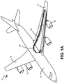
- FIG. 1A is a perspective view illustrating a portion of the fuel storage tanks onboard an aircraft. Shown in FIG. 1A is aircraft 10, fuselage 12, wings 14, engines 18, wing fuel tank 20, and center fuel tank 22.
- Aircraft 10 is an example of an aircraft in which an integral fluid measurement system may be employed.
- aircraft 10 has fuselage 12, two wings 14, and four engines 18.
- Fuselage 12 encloses the payload area of aircraft 10, typically consisting of passengers and cargo. Operating personnel, instrumentation, and control systems are also contained within fuselage 12.
- Wings 14 provide aerodynamic lift for airplane 10, while also holding engines 18.
- Engines 18 consume fuel to create thrust for airplane 10.
- Wing fuel tank 20 and center fuel tank 22 hold fuel, which is consumed by engines 18.
- Wing fuel tank 20 and center fuel tank 22 are exemplary of a plurality of fuel tanks that may be located in aircraft 10. Those who are skilled in the art of aircraft construction are familiar with the locations of various fuel tanks that may be located therein.
- various fuel tanks within aircraft 10 may be filled with fuel which is consumed by engines 18 during flight.
- crew members and/or systems aboard aircraft 10 may obtain knowledge of the inventory of fuel that exists in each of the various fuel tanks to calculate the mass and/or weight, and mass and/or weight distribution, of fuel stored throughout aircraft 10.
- mass and weight may be used interchangeably in describing a fuel parameter.
- aircraft 10 may be refueled during flight. Crew members and/or aboard aircraft 10 may obtain knowledge of the inventory of fuel in each of the various fuel tanks during the refueling operation and after the completion of the refueling operation.
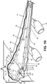
- FIG. 1B is a perspective view of the exemplary fuel tanks shown in FIG. 1A . Shown in FIG. 1B is wing fuel tank 20 and center fuel tank 22, tank wall 30, hybrid interface units 40, electrical cable 42, column sensors 60 and/or point sensors 62, electrical link 70, fiber optic link 72, RF link 74, optical pulse link 76, and sonic pulse link 78.
- wing fuel tank 20 and center fuel tank 22 are exemplary of a plurality of fuel tanks which may be located in aircraft 10.
- Wing fuel tank 20 and center fuel tank 22 each have tank wall 30.
- Located within aircraft 10 is a plurality of various fuel tanks, each having a shape and size that is designed to accommodate the space within which a fuel tank is located.
- wing fuel tank 20 has a generally long and tapered geometric shape that accommodates the interior of wing 14.
- Each fuel tank may have a particular geometric configuration, being comprised of a plurality of tank walls 30.
- a single tank wall 30 is identified on each of wing fuel tank 20 and center fuel tank 22.
- Hybrid interface units 40 are disposed on each of wing fuel tank 20 and center fuel tank 22, affixed upon a respective tank wall 30.
- Each hybrid interface unit 40 is electrically connected to an instrumentation and control system (not shown) by electrical cable 42.
- a plurality of column sensors 60 and point sensors 62 are disposed throughout wing fuel tank 20 and center fuel tank 22.
- Column sensors 60 are disposed in various areas throughout wing fuel tank 20 and center fuel tank 22, generally spanning the vertical height of wing fuel tank 20 and center fuel tank 22 to provide a range of fuel level sensing from full to empty.
- column sensors 60 may span only a portion of the vertical height of wing fuel tank 20 and center fuel tank 22.
- Column sensors 60 may employ one of several possible sensing technologies to detect one or more parameters associated with fuel.
- column sensors 60 may employ capacitive sensing to detect fuel level or to sense fuel dielectric.
- Point sensors 62 are disposed at various points throughout wing fuel tank 20 and center fuel tank 22, to detect a parameter associated with fuel at a particular point.
- Point sensor 62 may employ one of several possible sensing technologies to detect one or more parameters associated with fuel.
- point sensors 62 may employ resistive sensing to detect fuel temperature, or inductive sensing to detect fuel density.
- point sensor 62 may detect point level, identify whether or not a respective point sensor 62 is covered by fuel.
- column sensors 60 and/or point sensors 62 may be self-powered, drawing electrical power used for sensing a fuel parameter and transmitting data from an internal power supply (not shown). Alternatively, column sensors 60 and/or point sensors 62 may be powered from an external source, with the source of power being delivered through its data link or from another external source (not shown). Those who are skilled in the art of fuel sensors are familiar with various sensor designs that may be employed for detecting various parameters associated with fuel. Moreover, the skilled artesian will appreciate the reasons for multiple column sensors 60 and/or point sensors 62 being disposed throughout wing fuel tank 20 and center fuel tank 22, including the need to accurately measure fuel mass during various attitudes of aircraft 10 such as pitching, banking, and/or inverted flight.
- multiple communications technologies are utilized for the transmission of data from column sensors 60 and/or point sensors 62 to hybrid interface unit 40.
- a communication technology may also be referred to as a means of communication.
- two or more communication technologies may be deployed on column sensor 60 and/or point sensor 62.
- column sensor 60 and/or point sensor 62 may select between two or more communication technologies that are available.
- electrical link 70 communicates data from column sensors 60 and/or point sensors 62 to hybrid interface unit 40 by the transmission of electrical signals through electrical link 70.
- Electrical link 70 may be a single wire or a multiple-conductor cable. Electrical link 70 may directly connect column sensors 60 and/or point sensors 62 to hybrid interface unit 40. Electrical link 70 may also indirectly connect column sensors 60 and/or point sensors 62 to hybrid interface unit 40 via a different column sensors 60 and/or point sensors 62 using a daisy-chain configuration. Both the direct and indirect connections are depicted in FIG. 1B .
- fiber optic link 72 communicates data from column sensors 60 and/or point sensors 62 to hybrid interface unit 40 by the transmission of optical signals through fiber optic link 72.
- Fiber optic link 72 may be a single optical fiber or a bundle of optical fibers. Fiber optic link 72 may directly connect column sensors 60 and/or point sensors 62 to hybrid interface unit 40. Fiber optic link 72 may also indirectly connect column sensors 60 and/or point sensors 62 to hybrid interface unit 40 via different column sensors 60 and/or point sensors 62 using a daisy-chain configuration. Both the direct and indirect connections are depicted in FIG. 1B .
- RF link 74 communicates data from column sensors 60 and/or point sensors 62 to hybrid interface unit 40 by the transmission of RF electromagnetic signals that propagate through the interior of wing fuel tank 20 and center fuel tank 22.
- RF link 74 may transmit RF electromagnetic signals using any polarization topology including, without limitation, planar, circular, and planar cross-polarized transmission.
- RF link 74 may utilize an electromagnetic frequency band that is selected for propagation through fuel.
- RF signal propagation is though gas and RF link 74 may utilize an electromagnetic frequency band that is selected for propagation through gas.
- the gas may be air or fuel vapor.
- an inert gas may be used to replace fuel as it is consumed.
- optical pulse link 76 communicates data from column sensors 60 and/or point sensors 62 to hybrid interface unit 40 by the transmission of optical pulses that propagate through the interior of wing fuel tank 20 and/or center fuel tank 22.
- Optical pulses may have a wavelength in the infrared light range. In some embodiments, optical pulses may have a wavelength in the visible or ultraviolet light range.
- optical pulse propagation is though fuel and optical pulse link 76 may utilize an optical wavelength that is selected for propagation through fuel.
- optical pulse propagation is though gas and optical pulse link 76 may utilize an optical wavelength that is selected for propagation through gas.
- the gas may be air or fuel vapor.
- an inert gas may be used to replace fuel as it is consumed.
- sonic pulse link 78 communicates data from column sensors 60 and/or point sensors 62 to hybrid interface unit 40 by the transmission of sonic pulses that propagate through the interior of wing fuel tank 20 and/or center fuel tank 22.
- Sonic pulses may also be referred to as acoustical pulses.
- Acoustical pulses may have a frequency in the audible frequency range.
- acoustical pulses may have a frequency in the ultrasonic frequency range.
- acoustical pulse propagation is though gas and sonic pulse link 78 may utilize an acoustical frequency that is selected for propagation through gas.
- the gas may be air or fuel vapor.
- an inert gas may be used to replace fuel as it is consumed.
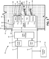
- FIG. 2 is schematic block diagram of the hybrid interface unit. Shown in FIG. 2 is tank wall 30, fuel tank exterior 32, fuel tank interior 34, tank wall mounting apparatus 36, hybrid interface unit 40, electrical cables 42, power supply 44, data bus 46, digital signal processor 48, hybrid interface 50, calculating device 52, electrical module 170, electrical connections 180, electrical link 70, fiber optic module 172, fiber optic connections 182, fiber optic link 72, RF module 174, RF antenna 184, RF link 74, optical pulse module 176, optical transducer 186, optical pulse link 76, sonic pulse module 178, acoustical transducer 188, and sonic pulse link 78.
- tank wall 30 has fuel tank exterior 32 on the outside, accessible within fuselage 12 or within wing 14 of aircraft 10 as shown in FIG. 1A .
- Tank wall 30 has fuel tank interior 34 on the inside, which may contain fuel, fuel vapor, air, or an inert gas as described in FIG. 1B .
- Hybrid interface unit 40 is disposed on tank wall 30, being affixed to tank wall 30 by tank wall mounting apparatus 36.
- tank wall mounting apparatus 36 Those who are skilled in the art of fuel tanks are familiar with methods and apparatus used to attach various components to fuel tanks, allowing penetration of tank wall 30 while excluding the leakage of fuel.
- Hybrid interface unit 40 is depicted as a block diagram in FIG. 2 , being comprised of several functional components.
- Power supply 44 receives electrical power from an electrical bus (not shown) on aircraft 10 via electrical cable 42.
- Power supply 44 provides electrical power to digital signal processor 48, to hybrid interface 50, and to all other circuit components of hybrid interface unit 40.
- Data bus 46 receives data from, and transmits data to, calculating device 52 on aircraft 10 via electrical cable 42.
- Electrical cable 42 may be two separate cables as depicted in FIG. 2 . In some embodiments, electrical cable 42 may also be a single cable as depicted in FIG. 1A , containing several electrical conductors. In some embodiments, electrical cable 42 may transmit power and data over the same conductor.
- data bus 46 is a serial data communications bus.
- data bus 46 may comply with any of a number of industry data bus standards including, without limitation, RS-482, RS-485, RS-422, RS-423, RS-232, Controller Area Network (CAN), and Ethernet.
- CAN Controller Area Network
- a new data bus standard may be developed for data bus 46, whether the new standard is proprietary, experimental, or it becomes a new industry standard.
- a parallel data bus standard may be used with data bus 46 instead of a serial data bus.
- hybrid interface 50 is comprised of multiple data communications modules, with each of the data communications modules representing a different means of data communication.
- Electrical module 170 communicates with various column sensors 60 and/or point sensors 62 by means of electrical link 70.
- Electrical module 170 contains a plurality of electrical connections 180 within fuel tank interior 34.
- Electrical link 70 may directly connect column sensors 60 and/or point sensors 62 to electrical module 170 via electrical connection 180.
- Electrical link 70 may also indirectly connect column sensors 60 and/or point sensors 62 to electrical module 170 via a different column sensors 60 and/or point sensors 62 using a daisy-chain configuration as described in FIG. 1B .
- Each of the plurality of electrical connections 180 on electrical module 170 may be connected to an electrical cable that comprises electrical link 70.
- any individual electrical connection may be terminated.
- electrical connection 180 may be self-terminating when not connected. Those who are skilled in the art of fuel sensors are familiar with methods of terminating or attaching electrical cables to electrical connections 180 within a fuel tank.
- Fiber optic module 172 communicates with various column sensors 60 and/or point sensors 62 by means of fiber optic link 72.
- Fiber optic module 172 contains a plurality of fiber optic connections 182 within fuel tank interior 34.
- Fiber optic link 72 may directly connect column sensors 60 and/or point sensors 62 to fiber optic module 172 via fiber optic link connection 182.
- Fiber optic link 72 may also indirectly connect column sensors 60 and/or point sensors 62 to fiber optic module 172 via a different column sensors 60 and/or point sensors 62 using a daisy-chain configuration as described in FIG. 1B .
- Each of the plurality of fiber optic connections 182 on fiber optic module 172 may be connected to a fiber cable that comprises fiber optic link 72.
- any individual fiber optic connection may be terminated.
- fiber optic connection 182 may be self-terminating when not connected. Those who are skilled in the art of fuel sensors are familiar with methods of terminating or attaching fiber optic cables to fiber optic connections 182 within a fuel tank.
- RF module 174 communicates with various column sensors 60 and/or point sensors 62 by means of RF link 74.
- RF module 174 contains RF antenna 184 within fuel tank interior 34.
- RF module 174 communicates with column sensors 60 and/or point sensors 62 by transmitting and receiving RF electromagnetic signals from RF antenna 184 via RF link 74.
- Different electromagnetic frequencies may be used to propagate through fuel and through the gas that replaces fuel as fuel is consumed, as described in FIG. 1B .
- different RF modulation modes may be used in RF link 74. Examples of modulation modes include, without limitation, amplitude frequency modulation, frequency modulation, phase modulation, and pulse code modulation.
- Optical pulse module 176 communicates with various column sensors 60 and/or point sensors 62 by means of optical pulse link 76.
- Optical pulse module 176 contains optical transducer 186 within fuel tank interior 34.
- Optical pulse module 176 communicates with column sensors 60 and/or point sensors 62 by transmitting and receiving optical pulse signals from optical transducer 186 via optical pulse link 76.
- Different optical wavelengths may be used to propagate through fuel and through the gas that replaces the fuel, as described in FIG. 1B .
- different optical modulation modes may be used in optical pulse link 76.
- Sonic pulse module 178 communicates with various column sensors 60 and/or point sensors 62 by means of sonic pulse link 78.
- Sonic pulse module 178 contains acoustical transducer 188 within fuel tank interior 34.
- Sonic pulse module 178 communicates with column sensors 60 and/or point sensors 62 by transmitting and receiving acoustical signals from acoustic transducer 188 via sonic pulse link 78.
- Different acoustical frequencies may be used to propagate through fuel and through the gas that replaces the fuel, as described in FIG. 1B .
- different sonic modulation modes may be used in sonic pulse link 78.
- hybrid interface 50 may be comprised of fewer than five data communications modules. In some embodiments, hybrid interface 50 may be comprised of a means of sensor data communication different from the means of communication described here. Any embodiment in which at least two means of sensor data communication are used is within the scope of the present disclosure.
- hybrid interface unit 40 may be programmed to address sensors that are within a tank that is supported by hybrid interface unit 40. In some embodiments, hybrid interface unit 40 may assign or re-assign addresses to sensors that are disposed within a fuel tank that is supported by hybrid interface unit 40. In some embodiments, hybrid interface 40 may auto-detect sensors and assign a new address to each detected sensor. In some embodiments, hybrid interface unit 40 may perform an accumulation node function for column sensors 60 and/or point sensors 62 that are daisy chained as distributed nodes. Hybrid interface unit 40 detects, determines the number of, and assigns a unique address to each column sensors 60 and/or point sensors 62 along the daisy chain. In some embodiments, hybrid interface unit may also generate and assign parameters regarding communication protocol, including, without limitation, update rate, data resolution, and scaling parameters.
- hybrid interface unit 40 has a scalable system architecture (not shown), meaning that when additional sensors are introduced, hybrid interface unit can modify the sensor addressing methodology to accommodate the additional sensors.
- hybrid interface unit 40 is capable of synchronizing with a plurality of hybrid interface units, meaning that multiple hybrid interface units may be employed on a particular fuel tank, each hybrid interface unit being capable of addressing and receiving data from a network of sensors within a particular tank.
- additional styles of sensors may be addressed by hybrid interface unit 40 other than column sensors 60 and/or point sensors 62 described above. In some embodiments, additional styles of sensors may select between two or more communication technologies that are available. In some embodiments, the communication technology and the mode of modulation used by a particular communication technology may be scaled to match the particular technology being used by column sensors 60 and/or point sensors 62.
- additional communications means may be added to hybrid interface unit 40 beyond electrical link 70, fiber optic link 72, RF link 74, optical pulse link 76, and sonic pulse link 78 as described above.
Landscapes
- Physics & Mathematics (AREA)
- General Physics & Mathematics (AREA)
- Engineering & Computer Science (AREA)
- Signal Processing (AREA)
- Aviation & Aerospace Engineering (AREA)
- Fluid Mechanics (AREA)
- Arrangements For Transmission Of Measured Signals (AREA)
Claims (15)
- Integrales Fluidmesssystem, umfassend:
eine Hybridschnittstelleneinheit (40) zum Kommunizieren mit einem oder mehreren Sensoren (60, 62), die in einem Fluidtank (20, 22) angeordnet sind, wobei die Hybridschnittstelleneinheit (40) umfasst:eine Hybridschnittstelle (50), wobei die Hybridschnittstelle (50) dazu konfiguriert ist, mit einem ersten Sensor (60, 62), der in dem Fluidtank (20, 22) angeordnet ist, mittels einer ersten Kommunikationstechnik zu kommunizieren und mit einem zweiten Sensor (60, 62), der in dem Fluidtank (20, 22) angeordnet ist, mittels einer zweiten Kommunikationstechnik zu kommunizieren, die sich von der ersten Kommunikationstechnik unterscheidet;eine Datenbusschnittstelle (46); undeinen digitalen Signalprozessor (48), wobei der digitale Signalprozessor (48) dazu konfiguriert ist, Daten zwischen der Hybridschnittstelle (50) und der Datenbusschnittstelle (46) auszutauschen;einen Fluidtank (20, 22), der dazu konfiguriert ist, ein Fluid zu enthalten; undeine Rechenvorrichtung (52), die dazu konfiguriert ist, Daten von der Datenbusschnittstelle (46) zu empfangen;wobei die Daten mindestens einen Parameter darstellen, der mit dem Fluid assoziiert ist; unddie Rechenvorrichtung (52) dazu konfiguriert ist, mindestens einen Parameter zu berechnen, der mit dem Fluid assoziiert ist. - Integrales Fluidmesssystem nach Anspruch 1, wobei es sich bei dem mindestens einen Parameter um ein Gewicht des Fluids handelt.
- Integrales Fluidmesssystem nach Anspruch 1 oder 2, wobei die Hybridschnittstelle (50) dazu konfiguriert ist, mit einem dritten Sensor (60, 62) mittels einer dritten Kommunikationstechnik zu kommunizieren.
- Integrales Fluidmesssystem nach Anspruch 3, wobei die Hybridschnittstelle (50) dazu konfiguriert ist, mit einem vierten Sensor (60, 62) mittels einer vierten Kommunikationstechnik zu kommunizieren.
- Anspruch 4, wobei die Hybridschnittstelle (50) dazu konfiguriert ist, mit einem fünften Sensor (60, 62) mittels einer fünften Kommunikationstechnik zu kommunizieren.
- Integrales Fluidmesssystem nach einem vorhergehenden Anspruch, wobei:die erste Kommunikationstechnik ausgewählt ist aus der Gruppe, bestehend aus elektrisch und faseroptisch; unddie zweite Kommunikationstechnik ausgewählt ist aus der Gruppe, bestehend aus Hochfrequenz, optischem Puls und Schallpuls.
- Integrales Fluidmesssystem nach einem vorhergehenden Anspruch, wobei die Hybridschnittstelle (50) skalierbar ist, um weitere Sensoren (60, 62) aufzunehmen.
- Integrales Fluidmesssystem nach Anspruch 7, wobei die Hybridschnittstelle (50) dazu imstande ist, weiteren Sensoren (60, 62) Adressen zuzuweisen.
- Verfahren zum Zusammenbauen eines integralen Fluidmesssystems, umfassend die Schritte:Anordnen einer Hybridschnittstelleneinheit (40) an einem Fluidtank (20, 22), wobei die Hybridschnittstelleneinheit (40) aus Folgendem besteht:einer Hybridschnittstelle (50), wobei die Hybridschnittstelle (50) dazu konfiguriert ist, mit einem ersten Sensor (60, 62), der in dem Fluidtank (20, 22) angeordnet ist, mittels einer ersten Kommunikationstechnik zu kommunizieren und mit einem zweiten Sensor (60, 62), der in dem Fluidtank (20, 22) angeordnet ist, mittels einer zweiten Kommunikationstechnik zu kommunizieren, die sich von der ersten Kommunikationstechnik unterscheidet;einer Datenbusschnittstelle (46); undeinem digitalen Signalprozessor (48), wobei der digitale Signalprozessor (48) dazu konfiguriert ist, Daten zwischen der Hybridschnittstelle (50) und der Datenbusschnittstelle (46) auszutauschen;Anbringen einer Vielzahl von Sensoren (60, 62) innerhalb des Fluidtanks (20, 22);kommunikatives Verbinden der Hybridschnittstelleneinheit (40) mit der Vielzahl von Sensoren (60, 62); undKoppeln der Hybridschnittstelleneinheit (40) mit einer Rechenvorrichtung (52).
- Verfahren nach Anspruch 9, wobei:die erste Kommunikationstechnik ausgewählt ist aus der Gruppe, bestehend aus elektrisch, faseroptisch, Hochfrequenz, optischem Puls und Schallpuls; unddie zweite Kommunikationstechnik ausgewählt ist aus der Gruppe, bestehend aus elektrisch, faseroptisch, Hochfrequenz, optischem Puls und Schallpuls.
- Verfahren nach Anspruch 9 oder 10, wobei zur Kopplung eine serielle Datenbusarchitektur verwendet wird.
- Verfahren nach Anspruch 11, wobei die serielle Datenbusarchitektur ausgewählt ist aus der Gruppe, bestehend aus: RS-482, RS-485, RS-422, RS-423, RS-232, Controller Area Network und Ethernet.
- Verfahren nach einem der Ansprüche 9-12, wobei zur Kopplung eine parallele Datenbusarchitektur verwendet wird.
- Verfahren nach einem der Ansprüche 9-13, wobei die Hybridschnittstelleneinheit (40) skalierbar ist, um weitere Sensoren (60, 62) aufzunehmen.
- Verfahren nach einem der Ansprüche 9-14, wobei die Hybridschnittstelleneinheit (40) dazu imstande ist, weiteren Sensoren (60, 62) eine Adresse zuzuweisen.
Applications Claiming Priority (1)
| Application Number | Priority Date | Filing Date | Title |
|---|---|---|---|
| US15/718,926 US10641645B2 (en) | 2017-09-28 | 2017-09-28 | Integral fluid measurement system |
Publications (2)
| Publication Number | Publication Date |
|---|---|
| EP3462141A1 EP3462141A1 (de) | 2019-04-03 |
| EP3462141B1 true EP3462141B1 (de) | 2020-08-05 |
Family
ID=63685866
Family Applications (1)
| Application Number | Title | Priority Date | Filing Date |
|---|---|---|---|
| EP18197170.6A Active EP3462141B1 (de) | 2017-09-28 | 2018-09-27 | Integrales fluidmesssystem |
Country Status (2)
| Country | Link |
|---|---|
| US (1) | US10641645B2 (de) |
| EP (1) | EP3462141B1 (de) |
Families Citing this family (5)
| Publication number | Priority date | Publication date | Assignee | Title |
|---|---|---|---|---|
| US11325720B2 (en) * | 2019-03-19 | 2022-05-10 | The Boeing Company | Electric power and data communications within a fuel tank and across a wall of the fuel tank using resistive non-metallic wire |
| US11305884B2 (en) | 2019-03-19 | 2022-04-19 | The Boeing Company | Electric power and data communications within a fuel tank and across a wall of the fuel tank using resistive non-metallic wire and an optical hybrid fuel height sensor |
| EP3961163A1 (de) * | 2020-08-31 | 2022-03-02 | Simmonds Precision Products, Inc. | Fluidmengensensorsystem |
| US11852518B2 (en) | 2021-05-19 | 2023-12-26 | The Boeing Company | Resistive wire wiring shield to prevent electromagnetic interference |
| DE102023103787A1 (de) * | 2023-02-16 | 2024-08-22 | Isud Solutions Gmbh | Analysevorrichtung zur Bestimmung einer Kenngröße eines Mediums, Sensoradapter und Verfahren zu seiner Herstellung |
Citations (1)
| Publication number | Priority date | Publication date | Assignee | Title |
|---|---|---|---|---|
| CN205748547U (zh) * | 2016-04-19 | 2016-11-30 | 罗斯蒙特储罐雷达股份公司 | 物位计量系统 |
Family Cites Families (14)
| Publication number | Priority date | Publication date | Assignee | Title |
|---|---|---|---|---|
| IT1213111B (it) | 1986-07-24 | 1989-12-07 | Nicotra Sistemi | Trasduttore singolo/multiplo, atto a rilevare una o piu' grandezze fisiche di diversa natura o variabili elettriche convenzionali. |
| US6115654A (en) | 1997-12-23 | 2000-09-05 | Simmonds Precision Products, Inc. | Universal sensor interface system and method |
| US7421895B1 (en) | 2005-04-21 | 2008-09-09 | Caldwell Joseph W | Fluid level measuring system |
| US8615374B1 (en) | 2006-06-09 | 2013-12-24 | Rockwell Automation Technologies, Inc. | Modular, configurable, intelligent sensor system |
| GB0802807D0 (en) | 2008-02-15 | 2008-03-26 | Rhodes Mark | Through water multimode communications system |
| US8473176B2 (en) * | 2008-04-07 | 2013-06-25 | John S. Youngquist | Aircraft monitoring equipment |
| US8281655B2 (en) | 2009-04-03 | 2012-10-09 | Eaton Corporation | Fuel gauging system utilizing a digital fuel gauging probe |
| US9856129B2 (en) * | 2010-10-18 | 2018-01-02 | Zonar Systems, Inc. | Method and apparatus for automatically monitoring fuel tank ullage in an automated fuel authorization program |
| US9020767B2 (en) | 2011-11-21 | 2015-04-28 | The Boeing Company | Wireless fuel monitoring system |
| US20140125496A1 (en) * | 2012-04-10 | 2014-05-08 | Omntec Mfg. Inc. | Universal Remote Display System |
| US9035800B2 (en) | 2012-10-12 | 2015-05-19 | The Boeing Company | Fuel tank monitoring system |
| US20140373622A1 (en) | 2013-06-21 | 2014-12-25 | Simmonds Precision Products, Inc. | Wireless fuel sensor |
| US9293033B2 (en) * | 2013-07-16 | 2016-03-22 | The Boeing Company | Wireless fuel sensor system |
| US10126158B2 (en) * | 2016-08-22 | 2018-11-13 | The Boeing Company | Systems and methods for determining a fuel level measurement of a fuel tank using optical sensor |
-
2017
- 2017-09-28 US US15/718,926 patent/US10641645B2/en active Active
-
2018
- 2018-09-27 EP EP18197170.6A patent/EP3462141B1/de active Active
Patent Citations (1)
| Publication number | Priority date | Publication date | Assignee | Title |
|---|---|---|---|---|
| CN205748547U (zh) * | 2016-04-19 | 2016-11-30 | 罗斯蒙特储罐雷达股份公司 | 物位计量系统 |
Also Published As
| Publication number | Publication date |
|---|---|
| US20190094062A1 (en) | 2019-03-28 |
| US10641645B2 (en) | 2020-05-05 |
| EP3462141A1 (de) | 2019-04-03 |
Similar Documents
| Publication | Publication Date | Title |
|---|---|---|
| EP3462141B1 (de) | Integrales fluidmesssystem | |
| US10362115B2 (en) | Wireless fuel sensor system | |
| US9909916B2 (en) | Wireless fuel sensor system | |
| JP5734971B2 (ja) | 無線信号のパワーハーベスティングによる無線検知のための方法および装置 | |
| EP2759478B1 (de) | Spitze mit Düsenbelastungsmessung und drahtlose Kommunikationsfunktion für Luftbetankung | |
| RU2678760C2 (ru) | Система беспроводных топливных датчиков | |
| KR20120082394A (ko) | 재구성가능한 비행기 | |
| EP3220175B1 (de) | Fluiddichtesensor mit optischer schnittstelle | |
| US20110199976A1 (en) | Wireless Aircraft Sensor Network | |
| RU2746416C2 (ru) | Система и способ для определения измеренного значения уровня топлива в топливном баке с использованием оптических датчиков, летательный аппарат | |
| US20180164140A1 (en) | Systems and Methods for Installation of Sensors for Fuel Quantity Indicating Systems | |
| EP3547548B1 (de) | Schnittstellensysteme und -verfahren zur fluidmessung | |
| EP3547547B1 (de) | Fluidcharakterisierungssystem mit integrierter dichtekompensation | |
| US20170234715A1 (en) | Sensor systems and methods | |
| EP3715860B1 (de) | Systeme und verfahren für digitale luftdaten | |
| Studor | " Fly-by-Wireless": A Revolution in Aerospace Vehicle Architecture for Instrumentation and Control |
Legal Events
| Date | Code | Title | Description |
|---|---|---|---|
| PUAI | Public reference made under article 153(3) epc to a published international application that has entered the european phase |
Free format text: ORIGINAL CODE: 0009012 |
|
| STAA | Information on the status of an ep patent application or granted ep patent |
Free format text: STATUS: THE APPLICATION HAS BEEN PUBLISHED |
|
| AK | Designated contracting states |
Kind code of ref document: A1 Designated state(s): AL AT BE BG CH CY CZ DE DK EE ES FI FR GB GR HR HU IE IS IT LI LT LU LV MC MK MT NL NO PL PT RO RS SE SI SK SM TR |
|
| AX | Request for extension of the european patent |
Extension state: BA ME |
|
| STAA | Information on the status of an ep patent application or granted ep patent |
Free format text: STATUS: REQUEST FOR EXAMINATION WAS MADE |
|
| 17P | Request for examination filed |
Effective date: 20190930 |
|
| RBV | Designated contracting states (corrected) |
Designated state(s): AL AT BE BG CH CY CZ DE DK EE ES FI FR GB GR HR HU IE IS IT LI LT LU LV MC MK MT NL NO PL PT RO RS SE SI SK SM TR |
|
| GRAP | Despatch of communication of intention to grant a patent |
Free format text: ORIGINAL CODE: EPIDOSNIGR1 |
|
| STAA | Information on the status of an ep patent application or granted ep patent |
Free format text: STATUS: GRANT OF PATENT IS INTENDED |
|
| RIC1 | Information provided on ipc code assigned before grant |
Ipc: G01G 17/04 20060101ALI20200213BHEP Ipc: G01F 23/00 20060101AFI20200213BHEP Ipc: G01G 1/00 20060101ALI20200213BHEP Ipc: G01D 21/02 20060101ALI20200213BHEP Ipc: B64D 37/02 20060101ALI20200213BHEP Ipc: B64D 37/00 20060101ALI20200213BHEP Ipc: G01D 21/00 20060101ALI20200213BHEP |
|
| INTG | Intention to grant announced |
Effective date: 20200311 |
|
| GRAS | Grant fee paid |
Free format text: ORIGINAL CODE: EPIDOSNIGR3 |
|
| GRAA | (expected) grant |
Free format text: ORIGINAL CODE: 0009210 |
|
| STAA | Information on the status of an ep patent application or granted ep patent |
Free format text: STATUS: THE PATENT HAS BEEN GRANTED |
|
| AK | Designated contracting states |
Kind code of ref document: B1 Designated state(s): AL AT BE BG CH CY CZ DE DK EE ES FI FR GB GR HR HU IE IS IT LI LT LU LV MC MK MT NL NO PL PT RO RS SE SI SK SM TR |
|
| REG | Reference to a national code |
Ref country code: GB Ref legal event code: FG4D |
|
| REG | Reference to a national code |
Ref country code: CH Ref legal event code: EP |
|
| REG | Reference to a national code |
Ref country code: AT Ref legal event code: REF Ref document number: 1299352 Country of ref document: AT Kind code of ref document: T Effective date: 20200815 |
|
| REG | Reference to a national code |
Ref country code: DE Ref legal event code: R096 Ref document number: 602018006634 Country of ref document: DE |
|
| REG | Reference to a national code |
Ref country code: IE Ref legal event code: FG4D |
|
| REG | Reference to a national code |
Ref country code: LT Ref legal event code: MG4D |
|
| REG | Reference to a national code |
Ref country code: NL Ref legal event code: MP Effective date: 20200805 |
|
| REG | Reference to a national code |
Ref country code: AT Ref legal event code: MK05 Ref document number: 1299352 Country of ref document: AT Kind code of ref document: T Effective date: 20200805 |
|
| PG25 | Lapsed in a contracting state [announced via postgrant information from national office to epo] |
Ref country code: AT Free format text: LAPSE BECAUSE OF FAILURE TO SUBMIT A TRANSLATION OF THE DESCRIPTION OR TO PAY THE FEE WITHIN THE PRESCRIBED TIME-LIMIT Effective date: 20200805 Ref country code: SE Free format text: LAPSE BECAUSE OF FAILURE TO SUBMIT A TRANSLATION OF THE DESCRIPTION OR TO PAY THE FEE WITHIN THE PRESCRIBED TIME-LIMIT Effective date: 20200805 Ref country code: HR Free format text: LAPSE BECAUSE OF FAILURE TO SUBMIT A TRANSLATION OF THE DESCRIPTION OR TO PAY THE FEE WITHIN THE PRESCRIBED TIME-LIMIT Effective date: 20200805 Ref country code: BG Free format text: LAPSE BECAUSE OF FAILURE TO SUBMIT A TRANSLATION OF THE DESCRIPTION OR TO PAY THE FEE WITHIN THE PRESCRIBED TIME-LIMIT Effective date: 20201105 Ref country code: GR Free format text: LAPSE BECAUSE OF FAILURE TO SUBMIT A TRANSLATION OF THE DESCRIPTION OR TO PAY THE FEE WITHIN THE PRESCRIBED TIME-LIMIT Effective date: 20201106 Ref country code: NO Free format text: LAPSE BECAUSE OF FAILURE TO SUBMIT A TRANSLATION OF THE DESCRIPTION OR TO PAY THE FEE WITHIN THE PRESCRIBED TIME-LIMIT Effective date: 20201105 Ref country code: LT Free format text: LAPSE BECAUSE OF FAILURE TO SUBMIT A TRANSLATION OF THE DESCRIPTION OR TO PAY THE FEE WITHIN THE PRESCRIBED TIME-LIMIT Effective date: 20200805 Ref country code: ES Free format text: LAPSE BECAUSE OF FAILURE TO SUBMIT A TRANSLATION OF THE DESCRIPTION OR TO PAY THE FEE WITHIN THE PRESCRIBED TIME-LIMIT Effective date: 20200805 Ref country code: PT Free format text: LAPSE BECAUSE OF FAILURE TO SUBMIT A TRANSLATION OF THE DESCRIPTION OR TO PAY THE FEE WITHIN THE PRESCRIBED TIME-LIMIT Effective date: 20201207 Ref country code: FI Free format text: LAPSE BECAUSE OF FAILURE TO SUBMIT A TRANSLATION OF THE DESCRIPTION OR TO PAY THE FEE WITHIN THE PRESCRIBED TIME-LIMIT Effective date: 20200805 |
|
| PG25 | Lapsed in a contracting state [announced via postgrant information from national office to epo] |
Ref country code: LV Free format text: LAPSE BECAUSE OF FAILURE TO SUBMIT A TRANSLATION OF THE DESCRIPTION OR TO PAY THE FEE WITHIN THE PRESCRIBED TIME-LIMIT Effective date: 20200805 Ref country code: RS Free format text: LAPSE BECAUSE OF FAILURE TO SUBMIT A TRANSLATION OF THE DESCRIPTION OR TO PAY THE FEE WITHIN THE PRESCRIBED TIME-LIMIT Effective date: 20200805 Ref country code: PL Free format text: LAPSE BECAUSE OF FAILURE TO SUBMIT A TRANSLATION OF THE DESCRIPTION OR TO PAY THE FEE WITHIN THE PRESCRIBED TIME-LIMIT Effective date: 20200805 Ref country code: NL Free format text: LAPSE BECAUSE OF FAILURE TO SUBMIT A TRANSLATION OF THE DESCRIPTION OR TO PAY THE FEE WITHIN THE PRESCRIBED TIME-LIMIT Effective date: 20200805 Ref country code: IS Free format text: LAPSE BECAUSE OF FAILURE TO SUBMIT A TRANSLATION OF THE DESCRIPTION OR TO PAY THE FEE WITHIN THE PRESCRIBED TIME-LIMIT Effective date: 20201205 |
|
| PG25 | Lapsed in a contracting state [announced via postgrant information from national office to epo] |
Ref country code: RO Free format text: LAPSE BECAUSE OF FAILURE TO SUBMIT A TRANSLATION OF THE DESCRIPTION OR TO PAY THE FEE WITHIN THE PRESCRIBED TIME-LIMIT Effective date: 20200805 Ref country code: CZ Free format text: LAPSE BECAUSE OF FAILURE TO SUBMIT A TRANSLATION OF THE DESCRIPTION OR TO PAY THE FEE WITHIN THE PRESCRIBED TIME-LIMIT Effective date: 20200805 Ref country code: DK Free format text: LAPSE BECAUSE OF FAILURE TO SUBMIT A TRANSLATION OF THE DESCRIPTION OR TO PAY THE FEE WITHIN THE PRESCRIBED TIME-LIMIT Effective date: 20200805 Ref country code: EE Free format text: LAPSE BECAUSE OF FAILURE TO SUBMIT A TRANSLATION OF THE DESCRIPTION OR TO PAY THE FEE WITHIN THE PRESCRIBED TIME-LIMIT Effective date: 20200805 Ref country code: SM Free format text: LAPSE BECAUSE OF FAILURE TO SUBMIT A TRANSLATION OF THE DESCRIPTION OR TO PAY THE FEE WITHIN THE PRESCRIBED TIME-LIMIT Effective date: 20200805 |
|
| REG | Reference to a national code |
Ref country code: DE Ref legal event code: R097 Ref document number: 602018006634 Country of ref document: DE |
|
| PG25 | Lapsed in a contracting state [announced via postgrant information from national office to epo] |
Ref country code: AL Free format text: LAPSE BECAUSE OF FAILURE TO SUBMIT A TRANSLATION OF THE DESCRIPTION OR TO PAY THE FEE WITHIN THE PRESCRIBED TIME-LIMIT Effective date: 20200805 Ref country code: MC Free format text: LAPSE BECAUSE OF FAILURE TO SUBMIT A TRANSLATION OF THE DESCRIPTION OR TO PAY THE FEE WITHIN THE PRESCRIBED TIME-LIMIT Effective date: 20200805 |
|
| PLBE | No opposition filed within time limit |
Free format text: ORIGINAL CODE: 0009261 |
|
| STAA | Information on the status of an ep patent application or granted ep patent |
Free format text: STATUS: NO OPPOSITION FILED WITHIN TIME LIMIT |
|
| REG | Reference to a national code |
Ref country code: BE Ref legal event code: MM Effective date: 20200930 |
|
| PG25 | Lapsed in a contracting state [announced via postgrant information from national office to epo] |
Ref country code: LU Free format text: LAPSE BECAUSE OF NON-PAYMENT OF DUE FEES Effective date: 20200927 Ref country code: SK Free format text: LAPSE BECAUSE OF FAILURE TO SUBMIT A TRANSLATION OF THE DESCRIPTION OR TO PAY THE FEE WITHIN THE PRESCRIBED TIME-LIMIT Effective date: 20200805 |
|
| 26N | No opposition filed |
Effective date: 20210507 |
|
| PG25 | Lapsed in a contracting state [announced via postgrant information from national office to epo] |
Ref country code: IT Free format text: LAPSE BECAUSE OF FAILURE TO SUBMIT A TRANSLATION OF THE DESCRIPTION OR TO PAY THE FEE WITHIN THE PRESCRIBED TIME-LIMIT Effective date: 20200805 |
|
| PG25 | Lapsed in a contracting state [announced via postgrant information from national office to epo] |
Ref country code: IE Free format text: LAPSE BECAUSE OF NON-PAYMENT OF DUE FEES Effective date: 20200927 Ref country code: SI Free format text: LAPSE BECAUSE OF FAILURE TO SUBMIT A TRANSLATION OF THE DESCRIPTION OR TO PAY THE FEE WITHIN THE PRESCRIBED TIME-LIMIT Effective date: 20200805 Ref country code: BE Free format text: LAPSE BECAUSE OF NON-PAYMENT OF DUE FEES Effective date: 20200930 |
|
| REG | Reference to a national code |
Ref country code: CH Ref legal event code: PL |
|
| PG25 | Lapsed in a contracting state [announced via postgrant information from national office to epo] |
Ref country code: TR Free format text: LAPSE BECAUSE OF FAILURE TO SUBMIT A TRANSLATION OF THE DESCRIPTION OR TO PAY THE FEE WITHIN THE PRESCRIBED TIME-LIMIT Effective date: 20200805 Ref country code: MT Free format text: LAPSE BECAUSE OF FAILURE TO SUBMIT A TRANSLATION OF THE DESCRIPTION OR TO PAY THE FEE WITHIN THE PRESCRIBED TIME-LIMIT Effective date: 20200805 Ref country code: CY Free format text: LAPSE BECAUSE OF FAILURE TO SUBMIT A TRANSLATION OF THE DESCRIPTION OR TO PAY THE FEE WITHIN THE PRESCRIBED TIME-LIMIT Effective date: 20200805 |
|
| PG25 | Lapsed in a contracting state [announced via postgrant information from national office to epo] |
Ref country code: MK Free format text: LAPSE BECAUSE OF FAILURE TO SUBMIT A TRANSLATION OF THE DESCRIPTION OR TO PAY THE FEE WITHIN THE PRESCRIBED TIME-LIMIT Effective date: 20200805 |
|
| PG25 | Lapsed in a contracting state [announced via postgrant information from national office to epo] |
Ref country code: LI Free format text: LAPSE BECAUSE OF NON-PAYMENT OF DUE FEES Effective date: 20210930 Ref country code: CH Free format text: LAPSE BECAUSE OF NON-PAYMENT OF DUE FEES Effective date: 20210930 |
|
| PGFP | Annual fee paid to national office [announced via postgrant information from national office to epo] |
Ref country code: GB Payment date: 20230823 Year of fee payment: 6 |
|
| PGFP | Annual fee paid to national office [announced via postgrant information from national office to epo] |
Ref country code: FR Payment date: 20230822 Year of fee payment: 6 Ref country code: DE Payment date: 20230822 Year of fee payment: 6 |