EP3462024B1 - Reciprocating type compressor - Google Patents
Reciprocating type compressor Download PDFInfo
- Publication number
- EP3462024B1 EP3462024B1 EP18196063.4A EP18196063A EP3462024B1 EP 3462024 B1 EP3462024 B1 EP 3462024B1 EP 18196063 A EP18196063 A EP 18196063A EP 3462024 B1 EP3462024 B1 EP 3462024B1
- Authority
- EP
- European Patent Office
- Prior art keywords
- cylinder
- axis
- compressor
- frame
- supporting portion
- Prior art date
- Legal status (The legal status is an assumption and is not a legal conclusion. Google has not performed a legal analysis and makes no representation as to the accuracy of the status listed.)
- Active
Links
Images




Classifications
-
- F—MECHANICAL ENGINEERING; LIGHTING; HEATING; WEAPONS; BLASTING
- F04—POSITIVE - DISPLACEMENT MACHINES FOR LIQUIDS; PUMPS FOR LIQUIDS OR ELASTIC FLUIDS
- F04B—POSITIVE-DISPLACEMENT MACHINES FOR LIQUIDS; PUMPS
- F04B39/00—Component parts, details, or accessories, of pumps or pumping systems specially adapted for elastic fluids, not otherwise provided for in, or of interest apart from, groups F04B25/00 - F04B37/00
- F04B39/0005—Component parts, details, or accessories, of pumps or pumping systems specially adapted for elastic fluids, not otherwise provided for in, or of interest apart from, groups F04B25/00 - F04B37/00 adaptations of pistons
-
- F—MECHANICAL ENGINEERING; LIGHTING; HEATING; WEAPONS; BLASTING
- F04—POSITIVE - DISPLACEMENT MACHINES FOR LIQUIDS; PUMPS FOR LIQUIDS OR ELASTIC FLUIDS
- F04B—POSITIVE-DISPLACEMENT MACHINES FOR LIQUIDS; PUMPS
- F04B39/00—Component parts, details, or accessories, of pumps or pumping systems specially adapted for elastic fluids, not otherwise provided for in, or of interest apart from, groups F04B25/00 - F04B37/00
- F04B39/12—Casings; Cylinders; Cylinder heads; Fluid connections
- F04B39/127—Mounting of a cylinder block in a casing
-
- F—MECHANICAL ENGINEERING; LIGHTING; HEATING; WEAPONS; BLASTING
- F04—POSITIVE - DISPLACEMENT MACHINES FOR LIQUIDS; PUMPS FOR LIQUIDS OR ELASTIC FLUIDS
- F04B—POSITIVE-DISPLACEMENT MACHINES FOR LIQUIDS; PUMPS
- F04B37/00—Pumps having pertinent characteristics not provided for in, or of interest apart from, groups F04B25/00 - F04B35/00
- F04B37/10—Pumps having pertinent characteristics not provided for in, or of interest apart from, groups F04B25/00 - F04B35/00 for special use
- F04B37/12—Pumps having pertinent characteristics not provided for in, or of interest apart from, groups F04B25/00 - F04B35/00 for special use to obtain high pressure
-
- F—MECHANICAL ENGINEERING; LIGHTING; HEATING; WEAPONS; BLASTING
- F04—POSITIVE - DISPLACEMENT MACHINES FOR LIQUIDS; PUMPS FOR LIQUIDS OR ELASTIC FLUIDS
- F04B—POSITIVE-DISPLACEMENT MACHINES FOR LIQUIDS; PUMPS
- F04B39/00—Component parts, details, or accessories, of pumps or pumping systems specially adapted for elastic fluids, not otherwise provided for in, or of interest apart from, groups F04B25/00 - F04B37/00
- F04B39/0027—Pulsation and noise damping means
- F04B39/0044—Pulsation and noise damping means with vibration damping supports
-
- F—MECHANICAL ENGINEERING; LIGHTING; HEATING; WEAPONS; BLASTING
- F04—POSITIVE - DISPLACEMENT MACHINES FOR LIQUIDS; PUMPS FOR LIQUIDS OR ELASTIC FLUIDS
- F04B—POSITIVE-DISPLACEMENT MACHINES FOR LIQUIDS; PUMPS
- F04B39/00—Component parts, details, or accessories, of pumps or pumping systems specially adapted for elastic fluids, not otherwise provided for in, or of interest apart from, groups F04B25/00 - F04B37/00
- F04B39/0094—Component parts, details, or accessories, of pumps or pumping systems specially adapted for elastic fluids, not otherwise provided for in, or of interest apart from, groups F04B25/00 - F04B37/00 crankshaft
-
- F—MECHANICAL ENGINEERING; LIGHTING; HEATING; WEAPONS; BLASTING
- F04—POSITIVE - DISPLACEMENT MACHINES FOR LIQUIDS; PUMPS FOR LIQUIDS OR ELASTIC FLUIDS
- F04B—POSITIVE-DISPLACEMENT MACHINES FOR LIQUIDS; PUMPS
- F04B39/00—Component parts, details, or accessories, of pumps or pumping systems specially adapted for elastic fluids, not otherwise provided for in, or of interest apart from, groups F04B25/00 - F04B37/00
- F04B39/10—Adaptations or arrangements of distribution members
-
- F—MECHANICAL ENGINEERING; LIGHTING; HEATING; WEAPONS; BLASTING
- F04—POSITIVE - DISPLACEMENT MACHINES FOR LIQUIDS; PUMPS FOR LIQUIDS OR ELASTIC FLUIDS
- F04B—POSITIVE-DISPLACEMENT MACHINES FOR LIQUIDS; PUMPS
- F04B39/00—Component parts, details, or accessories, of pumps or pumping systems specially adapted for elastic fluids, not otherwise provided for in, or of interest apart from, groups F04B25/00 - F04B37/00
- F04B39/12—Casings; Cylinders; Cylinder heads; Fluid connections
-
- F—MECHANICAL ENGINEERING; LIGHTING; HEATING; WEAPONS; BLASTING
- F04—POSITIVE - DISPLACEMENT MACHINES FOR LIQUIDS; PUMPS FOR LIQUIDS OR ELASTIC FLUIDS
- F04B—POSITIVE-DISPLACEMENT MACHINES FOR LIQUIDS; PUMPS
- F04B39/00—Component parts, details, or accessories, of pumps or pumping systems specially adapted for elastic fluids, not otherwise provided for in, or of interest apart from, groups F04B25/00 - F04B37/00
- F04B39/12—Casings; Cylinders; Cylinder heads; Fluid connections
- F04B39/121—Casings
-
- F—MECHANICAL ENGINEERING; LIGHTING; HEATING; WEAPONS; BLASTING
- F04—POSITIVE - DISPLACEMENT MACHINES FOR LIQUIDS; PUMPS FOR LIQUIDS OR ELASTIC FLUIDS
- F04B—POSITIVE-DISPLACEMENT MACHINES FOR LIQUIDS; PUMPS
- F04B39/00—Component parts, details, or accessories, of pumps or pumping systems specially adapted for elastic fluids, not otherwise provided for in, or of interest apart from, groups F04B25/00 - F04B37/00
- F04B39/12—Casings; Cylinders; Cylinder heads; Fluid connections
- F04B39/125—Cylinder heads
-
- F—MECHANICAL ENGINEERING; LIGHTING; HEATING; WEAPONS; BLASTING
- F04—POSITIVE - DISPLACEMENT MACHINES FOR LIQUIDS; PUMPS FOR LIQUIDS OR ELASTIC FLUIDS
- F04B—POSITIVE-DISPLACEMENT MACHINES FOR LIQUIDS; PUMPS
- F04B39/00—Component parts, details, or accessories, of pumps or pumping systems specially adapted for elastic fluids, not otherwise provided for in, or of interest apart from, groups F04B25/00 - F04B37/00
- F04B39/14—Provisions for readily assembling or disassembling
Definitions
- a reciprocating type compressor is disclosed herein.
- a compressor is an apparatus to increase pressure by compressing gas.
- the compressor is categorized into a reciprocating type compressor in which gas suctioned into a cylinder is compressed and discharged by a piston, and a scroll type compressor in which gas is compressed by rotating two scrolls relative to each other, based on how gas is compressed.
- a reciprocating type compressor 1 is based on a principle that a piston 40 that reciprocates in a direction of a second axis 92 compresses fluid introduced into a bore of a cylinder 30.
- a reciprocating type compressor as the piston 40 continuously reciprocates in the bore of the cylinder 30, shapes and dimensional accuracy of an inner diameter of the bore and an outer diameter of the piston 40 greatly affect efficiency of the compressor.
- a cylinder head 70 is coupled to an end of the cylinder 40.
- a cylinder with a block shape is provided with a tapped nut hole 31, and a portion of the cylinder head 70 corresponding to the nut hole 31 is provided with a through hole 71.
- the cylinder head 70 is fixed to the cylinder 30 by fastening a fastening bolt 80 to the nut hole 31 through the through hole 71
- deformation of the cylinder and the bore of the cylinder is caused by the process of fastening the fastening bolt 80 to the nut hole 31.
- Such deformation in an assembling process is not only difficult to predict but also is very difficult to control quantitatively. Therefore, even though the bore of the cylinder is precisely processed, a gap between the bore and the piston is changed from a designed dimension after the bore is deformed in the assembling process.
- a rotational shaft 50 rotates with respect to a first axis 91
- a crank pin 51 is eccentric with respect to the first axis 91 and is provided on the rotational shaft 50.
- the crank pin 51 circles around the first axis 91.
- Opposite ends of a connecting rod 46 are rotatably coupled to the piston 40 and the crank pin 51, respectively, so that the piston reciprocates in the bore of the cylinder as the rotational shaft rotates.
- the first axis 91 and the second axis 92 are orthogonal to each other.
- the cylinder 30 and a rotational supporting portion or support 25 of the rotational shaft have been manufactured as a single component in the conventional art.
- the cylinder and the rotational supporting portion are generally manufactured by casting.
- such a structure results in an increase in a manufacturing cost and a weight of the compressor.
- FR 2 161 727 A7 and DE 968 020 C discloses inner structures of reciprocating compressors.
- Embodiments disclosed herein provide a compressor having a structure in which a rotational supporting portion to support a rotational shaft and a cylinder are manufactured as separate components, and a frame provided with the rotational supporting portion may align and firmly support the rotational shaft and the cylinder.
- embodiments disclosed herein provide a compressor which may prevent deformation of a bore of the cylinder by allowing a cylinder head to be assembled into the cylinder through a frame that fixes the cylinder without being fixed directly to the cylinder.
- embodiments disclosed herein provide a compressor having a structure in which the frame that fixes the cylinder may support opposite ends of a crank pin of the rotational shaft, thereby greatly reducing a size and a weight of the compressor.
- a compressor according to embodiments disclosed herein may include a rotational shaft 50 to rotate with respect to a first axis 91, a cylinder 30 installed at a location spaced apart from the first axis 91 and provided with a bore that extends along a longitudinal direction of a second axis 92 orthogonal to the first axis 91, and a frame 30 to support the rotational shaft 50 and the cylinder 30.
- the frame may include a lower frame 24 provided with a lower rotational supporting portion 245 to support the rotational shaft 50 and a cylinder lower supporting portion 247 with the cylinder 30 mounted thereon to restrict a downward movement of the cylinder by supporting a lower portion of the cylinder, and an upper frame 23 provided with a cylinder upper supporting portion 237 that is fixed to the lower frame 24 at an upper portion of the lower frame 24 and mounted on an upper portion of the cylinder 30 to restrict an upward movement of the cylinder by supporting the upper portion of the cylinder.
- the lower frame 24 and the upper frame 23 may restrain the cylinder 30 from rotating with respect to an axis parallel with the first axis and rotating with respect to an axis perpendicular to both the first axis and the second axis.
- a lower side of a outer diameter portion or diameter of the cylinder 30 may be provided with a lower stopper boss 344 that protrudes downward from the outer diameter portion of the cylinder, and an end of the cylinder lower supporting portion 247 further from the lower rotational supporting portion 245 may be provided with a catch groove 243 into which the lower stopper boss 344 may be inserted, so as to restrain the cylinder 30 from rotating with respect to the second axis and moving in a direction toward the first axis along the second axis.
- a lower side of the outer diameter portion of the cylinder 30 may be provided with a temporary fastening boss 35 that protrudes downward from the outer diameter portion of the cylinder, and the lower rotational supporting portion 245 may be provided with a temporary fastening groove 244 having a shape corresponding to the temporary fastening boss 35, so that the temporary fastening boss 35 may be temporarily fastened to the temporary fastening groove 244 so as to restrain the cylinder 30 from rotating with respect to the second axis and moving in a longitudinal direction of the second axis.
- An upper side of the outer diameter portion of the cylinder 30 may be provided with an upper stopper boss 343 that protrudes upward from the outer diameter portion of the cylinder, and an end of the cylinder upper supporting portion 237 further from the first axis 91 may be provided with a catch groove 233 into which the upper stopper boss 343 is inserted, so as to restrain the cylinder 30 from rotating with respect to the second axis and moving in a direction toward the first axis along the second axis.
- the compressor may further include a cylinder head 70 coupled to an end of the cylinder 30 far from the first axis, a plurality of through holes 71 provided in the cylinder head 70, a plurality of nut holes provided in the frame and respectively formed at locations which face the through holes 71, and a fastening bolt 80 that passes through the through hole 71 to be coupled to the nut hole.
- the nut hole 231 may be provided in the upper frame 23 or the lower frame 24.
- the nut hole may be provided in a bent portion of the frame.
- the upper frame 23 and the lower frame 24 may be manufactured out of a metal plate by sheet metal forming.
- the upper frame 23 may be provided with an upper rotational supporting portion 235 to support the rotational shaft 50.
- the upper rotational supporting portion 235 may be spaced apart above from the lower rotational supporting portion 245.
- the compressor may further include a piston 40 inserted into the bore to reciprocate along a longitudinal direction of a second axis 92 perpendicular to the first axis 91, a crank pin 51 eccentrically disposed with respect to the rotation center of the rotational shaft 50 and parallel with the first axis 91, and a connecting rod 46 having one or a first end rotatably coupled to the crank pin 51 and the other or a second end rotatably coupled to the piston 40.
- the crank pin 51 may be disposed between the upper rotational supporting portion 235 and the lower rotational supporting portion 245.
- An end of the cylinder head 70 that faces the cylinder 30 may be provided with a catch groove 74 into which the stopper boss 34 may be inserted.
- At least one of a sealing member 32 or a check valve 33 may be interposed between the cylinder 30 and the cylinder head 70.
- a portion of the sealing member 32 or the check valve 33 corresponding to the stopper boss 34 may be provided with an alignment boss 323 and 333, and the alignment boss 323 and 333 may be inserted into the catch groove 74.
- An edge of the lower frame 24 may be provided with a vertical fastening hole 242, and an edge of the upper frame 23 may be provided with a vertical fastening hole 232.
- the vertical fastening holes 232 and 242 may be mutually aligned.
- the cylinder 30 may be configured in a cylinder shape.
- a frame to support a rotational supporting portion and a cylinder may be manufactured as separate components by sheet metal forming, and thereby the frame provided with the rotational supporting portion may align and firmly support a rotational shaft and the cylinder while reducing a weight of a product.
- Embodiments are not limited to the embodiments disclosed herein but may be implemented in various different forms.
- the embodiments are provided to make the descriptionthorough and to fully convey the scopeto those skilled in the art.
- FIGS. 3 to 8 A structure and operation principle of a reciprocating type compressor according to embodimentswill be described with reference to FIGS. 3 to 8 .
- a longitudinal direction of a rotational shaft 50 may be referred to as a vertical direction
- a direction in which the bore of cylinder 30 is seen may be referred to as "front”
- an opposite direction thereof may be referred as “rear”
- bilateral directions of the cylinder may be referred to as "lateral”.
- Each component of compressor 1 may be installed in a housing 10.
- the housing 10 may include a main housing 11 with a shape of a deep container, and a cover housing or cover 12 to cover and seal an upper portion of the main housing 11.
- a leg 13 may be provided at a lower portion of the main housing 11. The leg 13 may be configured to fix the compressor 1 to an installation location.
- a boss 15 may be provided at a bottom of an inner space of the housing 10.
- the boss 15 may fix an elastic device 16 such as, for example, a coil spring.
- An internal constituent element of the compressor may be fixed to an upper portion of the elastic device 16.
- the elastic device may fix the internal component of the compressor to the housing 10 while preventing the housing 10 and the internal component of the compressor from being directly connected to the housing. Therefore, the elastic device 16 may prevent vibration of the internal component of the compressor from being transferred to the housing 10.
- the internal component of the compressor may be fixed or supported by an upper frame 23 and a lower frame 24.
- the upper frame 23 and the lower frame 24 may be provided with an upper rotational supporting portion or support 235 and a lower rotational supporting portion or support 245 to support the rotational shaft 50, respectively.
- the two rotational supporting portions 235 and 245 may be aligned with each other along the first axis 91 (see FIG. 8 ).
- the two rotational supporting portions 235 and 245 may be provided with a bearing 26, and the rotational shaft 50 may be rotatably supported on the frames 23 and 24 by the bearing.
- the rotational shaft 50 may extend in the vertical direction, and may be rotatably supported by the frames 23 and 24 at two upper and lower points with the crank pin 51 positioned therebetween.
- the rotational shaft 50 may be supported at two points of a lower portion of the crank pin 51.
- the compressor according to the embodimentsshown in FIGS. 3 to 8 may have a structure in which the rotational shaft is supported at two points which respectively correspond to upper and lower portions of the crank pin 51.
- the rotational shaft 50 may rotate in a motor driving manner, and may be inverter-controlled.
- a stator 21 may be fixed to a lower portion of the lower frame 24.
- a rotor 52 may be fixed to the rotational shaft 50.
- a rotational force may be generated in the rotor 52 by inverter control, and accordingly the rotational shaft 50 may rotate.
- an inner rotor structure in which the rotor 52 is surrounded by the stator 21 is exemplified, but an outer rotor structure also may be applied.
- an outer rotor structure also may be applied.
- a torque of the rotational shaft generated by the rotor may increase, thereby reducing a length of the rotational shaft to that extent.
- the rotational shaft 50 may extend in the vertical direction. That is, the rotational shaft 50 may be disposed in the vertical direction.
- the rotational shaft 50 may rotate with respect to first axis 91 which is a vertical axis.
- crank pin 51 An upper portion of the rotational shaft 50 may be provided with the crank pin 51.
- the crank pin 51 may extend parallel with the first axis 91.
- the crank pin 51 may be located eccentrically from a center of the rotational shaft 50. Therefore, when the rotational shaft 50 rotates with respect to the first axis 91, the crank pin 51 may revolve around the first axis 91.
- a counterweight may be provided at a location that faces an eccentric location of the crank pin 51 with respect to the first axis 91, so as to prevent vibration of the rotational shaft 50.
- the cylinder 30 that extends in a horizontal direction may be provided at a height corresponding to that of the crank pin 51.
- the cylinder 30 of the compressor shown in FIGS. 1 and 2 may be constructed integrally with the rotational supporting portion 25.
- the cylinder 30 may be constructed as a separate component from the rotational supporting portion 25. That is, the cylinder 30 may constitute one component, and the frames 23 and 24 provided with the rotational supporting portions 235 and 245 may constitute other components. Then, the components may be mutually assembled so that the cylinder 30 and the rotational supporting portions 235 and 245 are mutually aligned.
- a bore of the cylinder 30 may be arranged in a direction of the second axis 92 that intersects perpendicularly to the first axis 91 which is the center of the rotational shaft 50. That is, the bore of the cylinder 30 may be arranged horizontally.
- the cylinder 30 may be spaced apart from the first axis 91 by a predetermined distance in a radial direction of the first axis.
- Piston 40 which reciprocates along a longitudinal direction of the bore, that is, a horizontal direction, may be inserted into the bore of the cylinder 30.
- a motional direction of the piston 40 may correspond to a direction of the second axis 92, and a center O of the piston 40 may be located on the second axis 92.
- the piston 40 and the crank pin 51 may be connected to each other by the connecting rod 46.
- the crank pin 51 may be inserted into one or a first end of the connecting rod 46, which may be rotatably connected to the crank pin 51.
- a rotational axis of one end of the connecting rod 46 with respect to the crank pin 51 may be parallel with the first axis 91.
- the other or a second end of the connecting rod 46 may be rotatably fastened to the piston 40 by a piston pin 42.
- a rotational axis of the other end of the connecting rod 46 with respect to the piston pin 42 may be also parallel with the first axis 91.
- the rotational shaft 50 may rotate with respect to the first axis 91. Then, the crank pin 51 may circle (revolve) around the first axis 91, and the piston 40 connected to the crank pin 51 via the connecting rod 46 may reciprocate along the second axis 92.
- a lubricating oil supplying portion 60 may be installed at a lower portion of the rotational shaft 50.
- Lubricating oil may be stored in a lower portion of an inner space of the housing 10.
- the lubricating oil supplying portion 60 may be submerged in the lubricating oil.
- the lubricating oil supplying portion 60 may be provided with a fixed portion 61 that maintains a fixed state without being rotated and a rotational portion 62 that rotates together with the rotational shaft 50.
- the fixed portion 61 may be fixed to the stator 21, and/or the lower frame 24, for example. Rotation of the rotational portion 62 relative to the fixed portion 61 may pump the lubricating oil upward.
- FIG. 2 shows a structure in which the fixed portion 61 having a spiral protruding portion formed on an outer circumferential surface thereof is fixed to the frame 20, and the rotational portion 62 that surrounds the fixed portion 61 is fixed to the rotational shaft 50 to rotate together with the rotational shaft 50.
- lubricating oil may be supplied upward in a spiral direction along the protruding portion of the fixed portion 61 by the viscosity of the lubricating oil.
- FIG. 8 shows a trochoid pump type lubricating oil supplying portion 60.
- the rotational shaft 50 may be provided with a hollow lubricating oil supply path 53.
- the lubricating oil supply path 53 may extend from a lower end of the rotational shaft to a vicinity of a location where lubrication is required.
- Oil lubricating oil
- Oil may be supplied to a gap portion or gap between the cylinder 30 and the piston 40, a connection portion between the crank pin 51 and the connecting rod 46, a vicinity of the piston pin 42 that is a connecting portion between the connecting rod 46 and the piston 40, and a supporting portion of the rotational shaft 50.
- the lubricating oil supplied to where lubricating oil is needed may flow down or fall back to the bottom of the housing 10 by gravity after lubricating a relevant portion.
- Cylinder head 70 may be installed at an end of the cylinder 30 located far or at a distance from the first axis 91, so as to cover the bore.
- the cylinder head 70 may be provided with a suction chamber 72 and a discharge chamber 73 that each communicate with the bore of the cylinder 30.
- At least one sealing member 32 may be compressed and interposed between the cylinder 30 and the cylinder head 70 to prevent fluid from leaking into a gap between the cylinder 30 and the cylinder head 70.
- a check valve 33 including a check valve portion disposed at a portion which allows the suction chamber 72 and the bore of the cylinder to communicate with each other therethough and a check valve portion disposed at a portion which allows the discharge chamber 73 and the bore of the cylinder to communicate with each other therethough.
- the at least one sealing member 32 may be interposed between the cylinder 30, the check valve 33 and the cylinder head 70 to prevent leakage of fluid.
- the check valve disposed at a portion where the suction chamber 72 and the bore of the cylinder communicate with each other may allow fluid in the suction chamber 72 to flow toward the bore of the cylinder, and may block the fluid from flowing in an opposite direction thereof.
- the check valve disposed at a portion where the discharge chamber 73 and the bore of the cylinder communicate with each other may allow fluid in the bore of the cylinder to flow toward the discharge chamber 73, and may block the fluid in an opposite direction thereof.
- the fluid in the suction chamber 72 may flow into the bore of the cylinder.
- the piston 40 moves toward the cylinder head 70, the fluid in the bore of the cylinder may be compressed and discharged to the discharge chamber 73.
- the lower frame 24 may be manufactured by processing a "T"-shaped sheet metal.
- a central portion of the lower frame 24 may be provided with the lower rotational supporting portion 245 through which the rotational shaft 50 passes.
- the lower rotational supporting portion 245 may be provided with the bearing 26.
- the rotational shaft 50 may be rotatably supported by the lower rotational supporting portion 245 through the bearing 26.
- the bearing 26 may be a thrust bearing.
- An inner circumferential surface of the supporting portion 245 may rotatably support an outer circumferential surface of the rotational shaft 50.
- An inner diameter portion or diameter of the lower rotational supporting portion 245, which is manufactured out of sheet metal, may be subjected to drawing processing to have a ring or donut shape that is convex downward. Accordingly, the inner diameter portion of the lower rotational supporting portion 245 may have a sufficient length in the vertical direction even when it is manufactured out of sheet metal. Further, a downward convex geometric shape may improve rigidity of a relevant portion.
- the bearing 26 may be received and supported in a space with a groove shape provided by such a shape.
- a lower cylinder supporting portion 247 to align and support the cylinder 30 may be provided at one side of the lower rotational supporting portion 245.
- the cylinder lower supporting portion 247 may be processed into a shape to surround a lower portion of the outer diameter portion of the cylinder 30 which is laid down.
- a lower stopper boss 344 that extends outward in a radial direction of the cylinder 30 may be formed at a lower fore-end of the outer diameter portion of the cylinder 30.
- the lower stopper boss 344 may extend along a direction of the second axis 92.
- a lower fore-end of the cylinder lower supporting portion 247 is provided with a catch groove 243 to receive at least a portion of the lower stopper boss 344 in a direction of the second axis 92.
- the cylinder 30 may be laid down on the cylinder lower supporting portion 247, and the lower stopper boss 344 of the cylinder 30 may be aligned with the catch groove 243 to be caught thereby.
- the cylinder lower supporting portion 247 may regulate a downward location of the cylinder 30.
- the catch groove 243 may restrain the cylinder 30 from rotating with respect to the second axis 92 and moving in a direction toward the lower rotational supporting portion 245 along a longitudinal direction of the second axis 92.
- FIG. 7 shows a modification of the lower stopper boss 344 shown in FIGS. 4 and 5 .
- an alignment boss 323 that extends outward in a radial direction of the cylinder 30 is provided in a vicinity of a center of a lower portion of the outer diameter portion of the cylinder 30.
- the alignment boss 323 has a circular sectional shape, a shape thereof is not limited thereto.
- a temporary fastening groove 244 having a shape corresponding to the alignment boss 323 to accommodate the alignment boss 323 may be provided at a portion of the cylinder lower supporting portion 247 corresponding to the alignment boss 323.
- the catch groove 243 and the lower stopper boss 344 to restrict the cylinder from moving in any one direction of the second axis 92 may differ from the alignment boss 323 and the temporary fastening groove 244 to restrict the cylinder from moving in bilateral directions of the second axis 92 in terms of a structure.
- Opposite ends of the cylinder lower supporting portion 247 each may be provided with an extending portion which extends laterally, and the extending portion may be provided with a vertical fastening hole 242.
- the other side of the lower rotational supporting portion 245 may be also provided with the extending portion, and the vertical fastening hole 242 also may be provided therein.
- the vertical fastening hole 242 may be formed at each of three locations close to an edge of the "T"-shaped a lower frame 24. This configuration is intended to be aligned with a vertical fastening hole 232 of the upper frame 23 to be described hereinafter, and to couple the two frames 23 and 24 by a fastening means such as a bolt, for example, to each other.
- the upper frame 23 also may be manufactured out of sheet metal.
- the upper rotational supporting portion 235 to support an upper end of the rotational shaft 50 may be provided at a central portion of the upper frame 23.
- an inner diameter portion or diameter of the upper rotational supporting portion 235 also may be subjected to a drawing processing to have a shape of a ring or a donut that is convex upward.
- the upper rotational supporting portion 235 may be aligned with the lower rotational supporting portion 245 in a vertical direction.
- the crank pin 51 of the rotational shaft 50 may be located in a space between the upper rotational supporting portion 235 and the lower rotational supporting portion 245.
- the upper rotational supporting portion 235 may support an upper end of the rotational shaft provided above the crank pin 51.
- a load of the piston 40 may be transferred to the crank pin 51.
- the rotational shaft may be supported at upper and lower opposite ends thereof on the basis of the crank pin 51, thereby firmly supporting the rotational shaft even when the rotational shaft is short.
- a periphery of the upper rotational supporting portion 235 may be configured in a shape of an umbrella so as to cover a space in which the crank pin 51 and the connecting rod 46 move.
- a cylinder upper supporting portion 237 to align and support the cylinder 30 may be provided at one or a first side of the upper rotational supporting portion 235.
- the cylinder upper supporting portion 237 may be processed to have a shape to cover an upper portion of the outer diameter portion of the cylinder 30 that is laid down.
- the cylinder upper supporting portion 237 and the cylinder lower supporting portion 247 may cooperate to surround an outer diameter circumference of the cylinder 30.
- An upper stopper boss 343 that extends in a radial direction of the cylinder may be formed at an upper fore-end of the outer diameter portion of the cylinder 30.
- the upper stopper boss 343 may be extended along a direction of the second axis.
- a fore-end of the cylinder upper supporting portion 237 may be provided with a catch groove 233 to receive at least a portion of the upper stopper boss 343 in a direction of the second axis 92.
- the cylinder upper supporting portion 237 may cover an upper portion of the cylinder. Accordingly, when the upper stopper boss 343 and the catch groove 233 are aligned with each other in the process of covering an upper portion of the cylinder with the cylinder upper supporting portion 237, all of the cylinder lower supporting portion 247, the cylinder 30, and the cylinder upper supporting portion 237 may be aligned.
- the cylinder upper supporting portion 237 may regulate an upper location of the cylinder 30.
- the catch groove 233 may retrain the cylinder 30 from rotating with respect to the second axis 92 and moving in a direction toward the lower rotational supporting portion 245 along a longitudinal direction of the second axis 92.
- the two cylinder supporting portions 237 and 247 may cooperate to restrain the cylinder 30 from rotating with respect to an axis parallel with the first axis and rotating with respect to an axis perpendicular to both the first axis and the second axis.
- a lower end of the cylinder upper supporting portion 237 may extend down to an upper surface of the lower frame 24.
- the lower end of the cylinder upper supporting portion 237 may extend laterally, and the extending portion may face and contact the upper surface of the lower frame 24, and the vertical fastening hole 232 may be provided in the extending portion.
- the vertical fastening hole 232 may face the vertical fastening hole 242 of the lower frame 24.
- the cylinder upper supporting portion 237 may gradually widen to correspond to a shape of the outer diameter of the cylinder as it extends toward a lower portion thereof from an upper portion thereof, and then may extend downward in the vertical direction after its widest point.
- the cylinder 30 may be more firmly supported between the cylinder upper supporting portion 237 and the cylinder lower supporting portion 247 of the two frames.
- the other side of the upper rotational supporting portion 235 also may be provided with an extending portion that extends obliquely downward.
- a portion where the extending portion is in contact with the upper surface of the lower frame 24 may be provided with the vertical fastening hole 232.
- the vertical fastening hole 232 may face the vertical fastening hole 242 located at the other side of the lower rotational supporting portion 245. Therefore, the upper rotational supporting portion 235 and the lower rotational supporting portion 245 may be fixed at minimum three points of a proper location in a circumferential direction with respect to the first axis 91, so as to firmly maintain a state in which the two rotational supporting portions 235 and 345 are aligned with each other.
- a bent portion that is bent upward may be provided at a rear end of the extending portion that extends ambilaterally from the cylinder upper supporting portion 237 of the upper frame 23.
- the bent portion may have a surface that faces frontward, and the nut hole 231 may be provided therein.
- the cylinder head 70 may have a portion that faces the cylinder 30 and a portion that extends ambilaterally therefrom.
- a through hole 71 may be formed in a portion that extends ambilaterally from the cylinder head 70, and the through hole 71 may be aligned with and face the nut hole 231 provided in the bent portion of the upper frame 23.
- An upper portion of a rear end of the cylinder head 70 may be provided with a catch groove 74 into which a portion of the front of the upper stopper boss 343 of the cylinder 30 may be inserted. Also, as shown in FIGS. 4 and 5 , when the cylinder 30 is provided with the lower stopper boss 344, a lower portion of the rear end of the cylinder head 70 also may be provided with the catch groove 71.
- the catch grooves 233 and 244 may be inserted and aligned in the rear of the stopper boss 34 of the cylinder 30.
- the cylinder head 70 may be inserted and aligned at the front of the stopper boss 34 of the cylinder 30. As a result, all of the frame 20, cylinder 30, and the cylinder head 70 may be aligned.
- the check valve 33 and the sealing members 32 may be interposed between the cylinder 30 and the cylinder head 70, and both the check valve 33 and the sealing members 32 need to be aligned. Therefore, the check valve 33 and the sealing members 32 also may be provided with alignment boss 323 and 333, respectively, at a location corresponding to the stopper boss 34.
- the alignment boss 323 and 333 of the check valve 33 and the sealing members 32 may be inserted into the catch groove 74 of the cylinder head 70, and subsequently stopper boss 34 of the cylinder 30 may be inserted, and thereby alignment may be precisely performed.
- the stopper boss 34, the alignment boss 323 and 333, and the catch groove 74 may be provided at upper and lower portions.
- the fastening bolt 80 may be fastened to the nut hole 231 of the upper frame 23 through the through hole 71 of the cylinder head 70.
- the nut hole 231 may have various structures in which an inner circumferential surface of the nut hole 231 is tapped, an additional nut is fixed to a rear of the nut hole 231 by means of welding, or a nut is disposed at the rear of the nut hole 231, for example.
- the upper frame 23 is not necessarily provided with the nut hole 231, but the lower frame 24 may have a bent portion, and a nut hole may be formed in the bent portion. That is, a shape of the nut hole is not limited to the shape shown in the drawings as long as the nut hole has a structure in which the cylinder head 70 is brought into close contact with the cylinder 30 so that the fastening bolt is indirectly fastened through the frame, for example, without being directly fastened to the cylinder.
- a fastening force of the fastening bolt may not affect the cylinder manufactured as a separate component from the frame to which the fastening bolt is fastened, so that the shape of the bore of the cylinder may not deformed. Therefore, a gap between the piston and the bore may not change after assembly.
- the cylinder it is not necessary to manufacture the cylinder in a block shape as shown in FIG. 1 . That is, it is enough that the cylinder is manufactured in a cylinder shape as shown in FIG. 3 , thereby greatly reducing a weight and a volume of the cylinder.
Landscapes
- Engineering & Computer Science (AREA)
- Mechanical Engineering (AREA)
- General Engineering & Computer Science (AREA)
- Compressor (AREA)
Description
- A reciprocating type compressor is disclosed herein.
- A compressor is an apparatus to increase pressure by compressing gas. The compressor is categorized into a reciprocating type compressor in which gas suctioned into a cylinder is compressed and discharged by a piston, and a scroll type compressor in which gas is compressed by rotating two scrolls relative to each other, based on how gas is compressed.
- Referring to
FIGS. 1 and2 , a reciprocatingtype compressor 1 is based on a principle that apiston 40 that reciprocates in a direction of asecond axis 92 compresses fluid introduced into a bore of acylinder 30. In the reciprocating type compressor, as thepiston 40 continuously reciprocates in the bore of thecylinder 30, shapes and dimensional accuracy of an inner diameter of the bore and an outer diameter of thepiston 40 greatly affect efficiency of the compressor. - A
cylinder head 70 is coupled to an end of thecylinder 40. A cylinder with a block shape is provided with a tappednut hole 31, and a portion of thecylinder head 70 corresponding to thenut hole 31 is provided with athrough hole 71. Thecylinder head 70 is fixed to thecylinder 30 by fastening a fasteningbolt 80 to thenut hole 31 through the throughhole 71 - However, deformation of the cylinder and the bore of the cylinder is caused by the process of fastening the
fastening bolt 80 to thenut hole 31. Such deformation in an assembling process is not only difficult to predict but also is very difficult to control quantitatively. Therefore, even though the bore of the cylinder is precisely processed, a gap between the bore and the piston is changed from a designed dimension after the bore is deformed in the assembling process. - In particular, when the gap between the piston and the bore of the cylinder is narrower than the designed dimension due to the deformed shape, an oil film of the lubricating oil is broken, and accordingly the piston and the bore of the cylinder are in direct contact with each other, resulting in deterioration in wear reliability of the piston and the bore of the cylinder.
- In view of this point, it is possible to prevent the oil film of the gap from being broken by making the gap between the piston and the bore of the cylinder a little wider, thereby ensuring the wear reliability even when the piston and the bore of the cylinder are deformed in the assembling process of the compressor. But, the widened gap may not maintain fluid-tightness, resulting in a reduction in compression efficiency.
- In the reciprocating type compressor, a
rotational shaft 50 rotates with respect to afirst axis 91, and acrank pin 51 is eccentric with respect to thefirst axis 91 and is provided on therotational shaft 50. Hence, when the rotational shaft 5 rotates, thecrank pin 51 circles around thefirst axis 91. Opposite ends of a connectingrod 46 are rotatably coupled to thepiston 40 and thecrank pin 51, respectively, so that the piston reciprocates in the bore of the cylinder as the rotational shaft rotates. Thefirst axis 91 and thesecond axis 92 are orthogonal to each other. - According to the above-described structure, alignment of the
first axis 91 and thesecond axis 92 is very important in order to ensure reliability of the compressor. In view of this point, thecylinder 30 and a rotational supporting portion or support 25 of the rotational shaft have been manufactured as a single component in the conventional art. For this purpose, the cylinder and the rotational supporting portion are generally manufactured by casting. However, such a structure results in an increase in a manufacturing cost and a weight of the compressor. - In addition, as the cylinder and the rotational supporting portion are integrally manufactured by casting, all the points to support the rotational shaft exist below the
second axis 92. Thus, it is difficult to firmly support the rotational shaft, and it is required to increase a vertical length of the rotational supporting portion so as to enhance the support reliability of the rotational shaft. Accordingly, a size of the compressor inevitably becomes larger. -
FR 2 161 727 A7 DE 968 020 C discloses inner structures of reciprocating compressors. - Embodiments disclosed herein provide a compressor having a structure in which a rotational supporting portion to support a rotational shaft and a cylinder are manufactured as separate components, and a frame provided with the rotational supporting portion may align and firmly support the rotational shaft and the cylinder.
- Further, embodiments disclosed herein provide a compressor which may prevent deformation of a bore of the cylinder by allowing a cylinder head to be assembled into the cylinder through a frame that fixes the cylinder without being fixed directly to the cylinder.
- Furthermore, embodiments disclosed herein provide a compressor having a structure in which the frame that fixes the cylinder may support opposite ends of a crank pin of the rotational shaft, thereby greatly reducing a size and a weight of the compressor.
- The invention is defined by the appended independent claim, and preferred aspects of the invention are defined by the appended dependent claims. A compressor according to embodiments disclosed herein may include a
rotational shaft 50 to rotate with respect to afirst axis 91, acylinder 30 installed at a location spaced apart from thefirst axis 91 and provided with a bore that extends along a longitudinal direction of asecond axis 92 orthogonal to thefirst axis 91, and aframe 30 to support therotational shaft 50 and thecylinder 30. The frame may include alower frame 24 provided with a lower rotational supportingportion 245 to support therotational shaft 50 and a cylinder lower supportingportion 247 with thecylinder 30 mounted thereon to restrict a downward movement of the cylinder by supporting a lower portion of the cylinder, and anupper frame 23 provided with a cylinder upper supportingportion 237 that is fixed to thelower frame 24 at an upper portion of thelower frame 24 and mounted on an upper portion of thecylinder 30 to restrict an upward movement of the cylinder by supporting the upper portion of the cylinder. Thelower frame 24 and theupper frame 23 may restrain thecylinder 30 from rotating with respect to an axis parallel with the first axis and rotating with respect to an axis perpendicular to both the first axis and the second axis. - A lower side of a outer diameter portion or diameter of the
cylinder 30 may be provided with alower stopper boss 344 that protrudes downward from the outer diameter portion of the cylinder, and an end of the cylinder lower supportingportion 247 further from the lower rotational supportingportion 245 may be provided with acatch groove 243 into which thelower stopper boss 344 may be inserted, so as to restrain thecylinder 30 from rotating with respect to the second axis and moving in a direction toward the first axis along the second axis. - A lower side of the outer diameter portion of the
cylinder 30 may be provided with atemporary fastening boss 35 that protrudes downward from the outer diameter portion of the cylinder, and the lower rotational supportingportion 245 may be provided with atemporary fastening groove 244 having a shape corresponding to thetemporary fastening boss 35, so that thetemporary fastening boss 35 may be temporarily fastened to thetemporary fastening groove 244 so as to restrain thecylinder 30 from rotating with respect to the second axis and moving in a longitudinal direction of the second axis. - An upper side of the outer diameter portion of the
cylinder 30 may be provided with anupper stopper boss 343 that protrudes upward from the outer diameter portion of the cylinder, and an end of the cylinder upper supportingportion 237 further from thefirst axis 91 may be provided with acatch groove 233 into which theupper stopper boss 343 is inserted, so as to restrain thecylinder 30 from rotating with respect to the second axis and moving in a direction toward the first axis along the second axis. - The compressor may further include a
cylinder head 70 coupled to an end of thecylinder 30 far from the first axis, a plurality of throughholes 71 provided in thecylinder head 70, a plurality of nut holes provided in the frame and respectively formed at locations which face the throughholes 71, and a fasteningbolt 80 that passes through thethrough hole 71 to be coupled to the nut hole. - The
nut hole 231 may be provided in theupper frame 23 or thelower frame 24. The nut hole may be provided in a bent portion of the frame. - The
upper frame 23 and thelower frame 24 may be manufactured out of a metal plate by sheet metal forming. - The
upper frame 23 may be provided with an upper rotational supportingportion 235 to support therotational shaft 50. The upper rotational supportingportion 235 may be spaced apart above from the lower rotational supportingportion 245. - The compressor may further include a
piston 40 inserted into the bore to reciprocate along a longitudinal direction of asecond axis 92 perpendicular to thefirst axis 91, acrank pin 51 eccentrically disposed with respect to the rotation center of therotational shaft 50 and parallel with thefirst axis 91, and a connectingrod 46 having one or a first end rotatably coupled to thecrank pin 51 and the other or a second end rotatably coupled to thepiston 40. Thecrank pin 51 may be disposed between the upper rotational supportingportion 235 and the lower rotational supportingportion 245. - An end of the
cylinder head 70 that faces thecylinder 30 may be provided with acatch groove 74 into which thestopper boss 34 may be inserted. - At least one of a
sealing member 32 or acheck valve 33 may be interposed between thecylinder 30 and thecylinder head 70. A portion of thesealing member 32 or thecheck valve 33 corresponding to thestopper boss 34 may be provided with an alignment boss 323 and 333, and the alignment boss 323 and 333 may be inserted into thecatch groove 74. - An edge of the
lower frame 24 may be provided with avertical fastening hole 242, and an edge of theupper frame 23 may be provided with avertical fastening hole 232. Thevertical fastening holes - The
cylinder 30 may be configured in a cylinder shape. - According to a compressor assembling method of embodiments disclosed herein, a frame to support a rotational supporting portion and a cylinder may be manufactured as separate components by sheet metal forming, and thereby the frame provided with the rotational supporting portion may align and firmly support a rotational shaft and the cylinder while reducing a weight of a product.
- Further, according to embodiments disclosed herein, it is possible to prevent deformation of a bore of the cylinder and reduce a volume of the cylinder by allowing a cylinder head to be assembled into the cylinder through a frame that fixes the cylinder without being fixed directly to the cylinder.
- Furthermore, according to embodiments disclosed herein, it is possible to support the rotational shaft at opposite ends of a crank pin through the frame, thereby firmly supporting the rotational shaft. Also, it is possible to reduce a length of the rotational shaft, thereby greatly reducing a volume of the compressor.
- Specific effects of the embodiments in addition to the above-described effects will be described together with the following details for carrying out the embodiments.
-
FIG. 1 is an exploded perspective view showing internal components of a reciprocating type compressor. -
FIG. 2 is a side sectional view of the compressor ofFIG. 1 . -
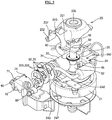
FIG. 3 is an exploded perspective view showing internal components of a reciprocating type compressor according to an embodiment. -
FIG. 4 is a top perspective view showing a combined state of a lower frame, an upper frame and a cylinder ofFIG. 3 . -
FIG. 5 is a front view ofFIG. 4 . -
FIG. 6 is a bottom perspective view ofFIG. 4 . -
FIG. 7 is a perspective view of the compressor ofFIG. 3 . -
FIG. 8 is a side sectional view of the compressor ofFIG. 7 . - Hereinafter, embodimentswill be described with reference to the accompanying drawings. Where possible, the same or similar reference numerals have been used to indicate the same or similar elements and repetitive disclosure has been omitted.
- Embodiments are not limited to the embodiments disclosed herein but may be implemented in various different forms. The embodiments are provided to make the descriptionthorough and to fully convey the scopeto those skilled in the art.
- A structure and operation principle of a reciprocating type compressor according to embodimentswill be described with reference to
FIGS. 3 to 8 . - For ease of explanation, a longitudinal direction of a
rotational shaft 50 may be referred to as a vertical direction, a direction in which the bore ofcylinder 30 is seen may be referred to as "front", an opposite direction thereof may be referred as "rear", and bilateral directions of the cylinder may be referred to as "lateral". - Each component of
compressor 1 may be installed in ahousing 10. Referring toFIGS. 7 and8 , thehousing 10 may include amain housing 11 with a shape of a deep container, and a cover housing or cover 12 to cover and seal an upper portion of themain housing 11. Aleg 13 may be provided at a lower portion of themain housing 11. Theleg 13 may be configured to fix thecompressor 1 to an installation location. - A
boss 15 may be provided at a bottom of an inner space of thehousing 10. Theboss 15 may fix anelastic device 16 such as, for example, a coil spring. An internal constituent element of the compressor may be fixed to an upper portion of theelastic device 16. The elastic device may fix the internal component of the compressor to thehousing 10 while preventing thehousing 10 and the internal component of the compressor from being directly connected to the housing. Therefore, theelastic device 16 may prevent vibration of the internal component of the compressor from being transferred to thehousing 10. - The internal component of the compressor may be fixed or supported by an
upper frame 23 and alower frame 24. Theupper frame 23 and thelower frame 24 may be provided with an upper rotational supporting portion orsupport 235 and a lower rotational supporting portion orsupport 245 to support therotational shaft 50, respectively. The two rotational supportingportions FIG. 8 ). The two rotational supportingportions bearing 26, and therotational shaft 50 may be rotatably supported on theframes - The
rotational shaft 50 may extend in the vertical direction, and may be rotatably supported by theframes crank pin 51 positioned therebetween. In the conventional compressor shown inFIGS. 1 and2 , therotational shaft 50 may be supported at two points of a lower portion of thecrank pin 51. On the other hand, the compressor according to the embodimentsshown inFIGS. 3 to 8 may have a structure in which the rotational shaft is supported at two points which respectively correspond to upper and lower portions of thecrank pin 51. - The
rotational shaft 50 may rotate in a motor driving manner, and may be inverter-controlled. Astator 21 may be fixed to a lower portion of thelower frame 24. Arotor 52 may be fixed to therotational shaft 50. A rotational force may be generated in therotor 52 by inverter control, and accordingly therotational shaft 50 may rotate. - In one embodiment, an inner rotor structure in which the
rotor 52 is surrounded by thestator 21 is exemplified, but an outer rotor structure also may be applied. When the outer rotor structure is applied, a torque of the rotational shaft generated by the rotor may increase, thereby reducing a length of the rotational shaft to that extent. - The
rotational shaft 50 may extend in the vertical direction. That is, therotational shaft 50 may be disposed in the vertical direction. Therotational shaft 50 may rotate with respect tofirst axis 91 which is a vertical axis. - An upper portion of the
rotational shaft 50 may be provided with thecrank pin 51. Thecrank pin 51 may extend parallel with thefirst axis 91. Thecrank pin 51 may be located eccentrically from a center of therotational shaft 50. Therefore, when therotational shaft 50 rotates with respect to thefirst axis 91, thecrank pin 51 may revolve around thefirst axis 91. A counterweight may be provided at a location that faces an eccentric location of thecrank pin 51 with respect to thefirst axis 91, so as to prevent vibration of therotational shaft 50. - The
cylinder 30 that extends in a horizontal direction may be provided at a height corresponding to that of thecrank pin 51. For reference, thecylinder 30 of the compressor shown inFIGS. 1 and2 may be constructed integrally with the rotational supporting portion 25. On the other hand, in the compressor according to embodiments, thecylinder 30 may be constructed as a separate component from the rotational supporting portion 25. That is, thecylinder 30 may constitute one component, and theframes portions cylinder 30 and the rotational supportingportions - A bore of the
cylinder 30 may be arranged in a direction of thesecond axis 92 that intersects perpendicularly to thefirst axis 91 which is the center of therotational shaft 50. That is, the bore of thecylinder 30 may be arranged horizontally. Thecylinder 30 may be spaced apart from thefirst axis 91 by a predetermined distance in a radial direction of the first axis. -
Piston 40, which reciprocates along a longitudinal direction of the bore, that is, a horizontal direction, may be inserted into the bore of thecylinder 30. A motional direction of thepiston 40 may correspond to a direction of thesecond axis 92, and a center O of thepiston 40 may be located on thesecond axis 92. - The
piston 40 and thecrank pin 51 may be connected to each other by the connectingrod 46. Thecrank pin 51 may be inserted into one or a first end of the connectingrod 46, which may be rotatably connected to the crankpin 51. A rotational axis of one end of the connectingrod 46 with respect to the crankpin 51 may be parallel with thefirst axis 91. - The other or a second end of the connecting
rod 46 may be rotatably fastened to thepiston 40 by apiston pin 42. A rotational axis of the other end of the connectingrod 46 with respect to thepiston pin 42 may be also parallel with thefirst axis 91. - By operation of
motors rotational shaft 50 may rotate with respect to thefirst axis 91. Then, thecrank pin 51 may circle (revolve) around thefirst axis 91, and thepiston 40 connected to the crankpin 51 via the connectingrod 46 may reciprocate along thesecond axis 92. - A lubricating
oil supplying portion 60 may be installed at a lower portion of therotational shaft 50. Lubricating oil may be stored in a lower portion of an inner space of thehousing 10. The lubricatingoil supplying portion 60 may be submerged in the lubricating oil. The lubricatingoil supplying portion 60 may be provided with a fixedportion 61 that maintains a fixed state without being rotated and arotational portion 62 that rotates together with therotational shaft 50. The fixedportion 61 may be fixed to thestator 21, and/or thelower frame 24, for example. Rotation of therotational portion 62 relative to the fixedportion 61 may pump the lubricating oil upward. -
FIG. 2 shows a structure in which the fixedportion 61 having a spiral protruding portion formed on an outer circumferential surface thereof is fixed to theframe 20, and therotational portion 62 that surrounds the fixedportion 61 is fixed to therotational shaft 50 to rotate together with therotational shaft 50. When therotational portion 62 rotates, lubricating oil may be supplied upward in a spiral direction along the protruding portion of the fixedportion 61 by the viscosity of the lubricating oil. On the other hand,FIG. 8 shows a trochoid pump type lubricatingoil supplying portion 60. - The
rotational shaft 50 may be provided with a hollow lubricatingoil supply path 53. The lubricatingoil supply path 53 may extend from a lower end of the rotational shaft to a vicinity of a location where lubrication is required. Oil (lubricating oil) may be supplied to a gap portion or gap between thecylinder 30 and thepiston 40, a connection portion between thecrank pin 51 and the connectingrod 46, a vicinity of thepiston pin 42 that is a connecting portion between the connectingrod 46 and thepiston 40, and a supporting portion of therotational shaft 50. - The lubricating oil supplied to where lubricating oil is needed may flow down or fall back to the bottom of the
housing 10 by gravity after lubricating a relevant portion. -
Cylinder head 70 may be installed at an end of thecylinder 30 located far or at a distance from thefirst axis 91, so as to cover the bore. Thecylinder head 70 may be provided with asuction chamber 72 and adischarge chamber 73 that each communicate with the bore of thecylinder 30. - At least one sealing
member 32 may be compressed and interposed between thecylinder 30 and thecylinder head 70 to prevent fluid from leaking into a gap between thecylinder 30 and thecylinder head 70. - Also, between the
cylinder 30 and thecylinder head 70, there may be installed acheck valve 33 including a check valve portion disposed at a portion which allows thesuction chamber 72 and the bore of the cylinder to communicate with each other therethough and a check valve portion disposed at a portion which allows thedischarge chamber 73 and the bore of the cylinder to communicate with each other therethough. - The at least one sealing
member 32 may be interposed between thecylinder 30, thecheck valve 33 and thecylinder head 70 to prevent leakage of fluid. - The check valve disposed at a portion where the
suction chamber 72 and the bore of the cylinder communicate with each other may allow fluid in thesuction chamber 72 to flow toward the bore of the cylinder, and may block the fluid from flowing in an opposite direction thereof. - The check valve disposed at a portion where the
discharge chamber 73 and the bore of the cylinder communicate with each other may allow fluid in the bore of the cylinder to flow toward thedischarge chamber 73, and may block the fluid in an opposite direction thereof. - Thus, when the
piston 40 moves in a direction away from thecylinder head 70 as therotational shaft 50 rotates by the motor, the fluid in thesuction chamber 72 may flow into the bore of the cylinder. When thepiston 40 moves toward thecylinder head 70, the fluid in the bore of the cylinder may be compressed and discharged to thedischarge chamber 73. - A combined structure of upper and lower frames and the cylinder will be described with reference to
FIGS. 3 to 8 . - The
lower frame 24 may be manufactured by processing a "T"-shaped sheet metal. A central portion of thelower frame 24 may be provided with the lower rotational supportingportion 245 through which therotational shaft 50 passes. The lower rotational supportingportion 245 may be provided with thebearing 26. Therotational shaft 50 may be rotatably supported by the lower rotational supportingportion 245 through thebearing 26. Thebearing 26 may be a thrust bearing. An inner circumferential surface of the supportingportion 245 may rotatably support an outer circumferential surface of therotational shaft 50. - An inner diameter portion or diameter of the lower rotational supporting
portion 245, which is manufactured out of sheet metal, may be subjected to drawing processing to have a ring or donut shape that is convex downward. Accordingly, the inner diameter portion of the lower rotational supportingportion 245 may have a sufficient length in the vertical direction even when it is manufactured out of sheet metal. Further, a downward convex geometric shape may improve rigidity of a relevant portion. In addition, the bearing 26 may be received and supported in a space with a groove shape provided by such a shape. - In the
lower frame 24, a lowercylinder supporting portion 247 to align and support thecylinder 30 may be provided at one side of the lower rotational supportingportion 245. The cylinder lower supportingportion 247 may be processed into a shape to surround a lower portion of the outer diameter portion of thecylinder 30 which is laid down. - Referring to
FIGS. 4 and 5 , alower stopper boss 344 that extends outward in a radial direction of thecylinder 30 may be formed at a lower fore-end of the outer diameter portion of thecylinder 30. Thelower stopper boss 344 may extend along a direction of thesecond axis 92. - A lower fore-end of the cylinder lower supporting
portion 247 is provided with acatch groove 243 to receive at least a portion of thelower stopper boss 344 in a direction of thesecond axis 92. Thecylinder 30 may be laid down on the cylinder lower supportingportion 247, and thelower stopper boss 344 of thecylinder 30 may be aligned with thecatch groove 243 to be caught thereby. - Therefore, the cylinder lower supporting
portion 247 may regulate a downward location of thecylinder 30. Thecatch groove 243 may restrain thecylinder 30 from rotating with respect to thesecond axis 92 and moving in a direction toward the lower rotational supportingportion 245 along a longitudinal direction of thesecond axis 92. -
FIG. 7 shows a modification of thelower stopper boss 344 shown inFIGS. 4 and 5 . First, an alignment boss 323 that extends outward in a radial direction of thecylinder 30 is provided in a vicinity of a center of a lower portion of the outer diameter portion of thecylinder 30. Although it is shown that the alignment boss 323 has a circular sectional shape, a shape thereof is not limited thereto. - A
temporary fastening groove 244 having a shape corresponding to the alignment boss 323 to accommodate the alignment boss 323 may be provided at a portion of the cylinder lower supportingportion 247 corresponding to the alignment boss 323. - The
catch groove 243 and thelower stopper boss 344 to restrict the cylinder from moving in any one direction of thesecond axis 92 may differ from the alignment boss 323 and thetemporary fastening groove 244 to restrict the cylinder from moving in bilateral directions of thesecond axis 92 in terms of a structure. - Opposite ends of the cylinder lower supporting
portion 247 each may be provided with an extending portion which extends laterally, and the extending portion may be provided with avertical fastening hole 242. In thelower frame 24, the other side of the lower rotational supportingportion 245 may be also provided with the extending portion, and thevertical fastening hole 242 also may be provided therein. - That is, the
vertical fastening hole 242 may be formed at each of three locations close to an edge of the "T"-shaped alower frame 24. This configuration is intended to be aligned with avertical fastening hole 232 of theupper frame 23 to be described hereinafter, and to couple the twoframes - The
upper frame 23 also may be manufactured out of sheet metal. - The upper rotational supporting
portion 235 to support an upper end of therotational shaft 50 may be provided at a central portion of theupper frame 23. In the same manner as the lower rotational supporting portion described above, an inner diameter portion or diameter of the upper rotational supportingportion 235 also may be subjected to a drawing processing to have a shape of a ring or a donut that is convex upward. The upper rotational supportingportion 235 may be aligned with the lower rotational supportingportion 245 in a vertical direction. - The
crank pin 51 of therotational shaft 50 may be located in a space between the upper rotational supportingportion 235 and the lower rotational supportingportion 245. The upper rotational supportingportion 235 may support an upper end of the rotational shaft provided above thecrank pin 51. As the compressor operates, a load of thepiston 40 may be transferred to the crankpin 51. In embodiments, the rotational shaft may be supported at upper and lower opposite ends thereof on the basis of thecrank pin 51, thereby firmly supporting the rotational shaft even when the rotational shaft is short. - A periphery of the upper rotational supporting
portion 235 may be configured in a shape of an umbrella so as to cover a space in which thecrank pin 51 and the connectingrod 46 move. - A cylinder upper supporting
portion 237 to align and support thecylinder 30 may be provided at one or a first side of the upper rotational supportingportion 235. The cylinder upper supportingportion 237 may be processed to have a shape to cover an upper portion of the outer diameter portion of thecylinder 30 that is laid down. The cylinder upper supportingportion 237 and the cylinder lower supportingportion 247 may cooperate to surround an outer diameter circumference of thecylinder 30. - An
upper stopper boss 343 that extends in a radial direction of the cylinder may be formed at an upper fore-end of the outer diameter portion of thecylinder 30. Theupper stopper boss 343 may be extended along a direction of the second axis. - A fore-end of the cylinder upper supporting
portion 237 may be provided with acatch groove 233 to receive at least a portion of theupper stopper boss 343 in a direction of thesecond axis 92. - In a state in which the
cylinder 30 is aligned on the cylinder lower supportingportion 247, the cylinder upper supportingportion 237 may cover an upper portion of the cylinder. Accordingly, when theupper stopper boss 343 and thecatch groove 233 are aligned with each other in the process of covering an upper portion of the cylinder with the cylinder upper supportingportion 237, all of the cylinder lower supportingportion 247, thecylinder 30, and the cylinder upper supportingportion 237 may be aligned. - The cylinder upper supporting
portion 237 may regulate an upper location of thecylinder 30. Thecatch groove 233 may retrain thecylinder 30 from rotating with respect to thesecond axis 92 and moving in a direction toward the lower rotational supportingportion 245 along a longitudinal direction of thesecond axis 92. The twocylinder supporting portions cylinder 30 from rotating with respect to an axis parallel with the first axis and rotating with respect to an axis perpendicular to both the first axis and the second axis. - A lower end of the cylinder upper supporting
portion 237 may extend down to an upper surface of thelower frame 24. The lower end of the cylinder upper supportingportion 237 may extend laterally, and the extending portion may face and contact the upper surface of thelower frame 24, and thevertical fastening hole 232 may be provided in the extending portion. Thevertical fastening hole 232 may face thevertical fastening hole 242 of thelower frame 24. - When the
upper frame 23 and thelower frame 24 are fixed through the vertical fastening holes 232 and 242 at opposite sides of the upper supportingportion 237 and the lower supportingportion 247 of the cylinder, it is possible to firmly fix theframes cylinder 30. - Referring to
FIG. 5 , the cylinder upper supportingportion 237 may gradually widen to correspond to a shape of the outer diameter of the cylinder as it extends toward a lower portion thereof from an upper portion thereof, and then may extend downward in the vertical direction after its widest point. When theupper frame 23 and thelower frame 24 are tightened by fastening bolts, for example, through the vertical fastening holes 232 and 242 at opposite sides of the upper supportingportion 237 and the lower supportingportion 247 of the cylinder, thecylinder 30 may be more firmly supported between the cylinder upper supportingportion 237 and the cylinder lower supportingportion 247 of the two frames. - The other side of the upper rotational supporting
portion 235 also may be provided with an extending portion that extends obliquely downward. A portion where the extending portion is in contact with the upper surface of thelower frame 24 may be provided with thevertical fastening hole 232. Thevertical fastening hole 232 may face thevertical fastening hole 242 located at the other side of the lower rotational supportingportion 245. Therefore, the upper rotational supportingportion 235 and the lower rotational supportingportion 245 may be fixed at minimum three points of a proper location in a circumferential direction with respect to thefirst axis 91, so as to firmly maintain a state in which the two rotational supportingportions 235 and 345 are aligned with each other. - Hereinafter, an assembling method of the
cylinder 30 and thecylinder head 70 will be described with reference toFIGS. 3 to 8 . - A bent portion that is bent upward may be provided at a rear end of the extending portion that extends ambilaterally from the cylinder upper supporting
portion 237 of theupper frame 23. The bent portion may have a surface that faces frontward, and thenut hole 231 may be provided therein. - The
cylinder head 70 may have a portion that faces thecylinder 30 and a portion that extends ambilaterally therefrom. A throughhole 71 may be formed in a portion that extends ambilaterally from thecylinder head 70, and the throughhole 71 may be aligned with and face thenut hole 231 provided in the bent portion of theupper frame 23. - An upper portion of a rear end of the
cylinder head 70 may be provided with acatch groove 74 into which a portion of the front of theupper stopper boss 343 of thecylinder 30 may be inserted. Also, as shown inFIGS. 4 and 5 , when thecylinder 30 is provided with thelower stopper boss 344, a lower portion of the rear end of thecylinder head 70 also may be provided with thecatch groove 71. - The
catch grooves stopper boss 34 of thecylinder 30. Thecylinder head 70 may be inserted and aligned at the front of thestopper boss 34 of thecylinder 30. As a result, all of theframe 20,cylinder 30, and thecylinder head 70 may be aligned. - The
check valve 33 and the sealingmembers 32 may be interposed between thecylinder 30 and thecylinder head 70, and both thecheck valve 33 and the sealingmembers 32 need to be aligned. Therefore, thecheck valve 33 and the sealingmembers 32 also may be provided with alignment boss 323 and 333, respectively, at a location corresponding to thestopper boss 34. - Then, the alignment boss 323 and 333 of the
check valve 33 and the sealingmembers 32 may be inserted into thecatch groove 74 of thecylinder head 70, and subsequentlystopper boss 34 of thecylinder 30 may be inserted, and thereby alignment may be precisely performed. For precise alignment of the aforementioned components, thestopper boss 34, the alignment boss 323 and 333, and thecatch groove 74 may be provided at upper and lower portions. - In a state in which the
cylinder head 70, the sealingmember 32, thecheck valve 33, the other sealingmember 32 and thecylinder 30 are aligned, thefastening bolt 80 may be fastened to thenut hole 231 of theupper frame 23 through the throughhole 71 of thecylinder head 70. - The
nut hole 231 may have various structures in which an inner circumferential surface of thenut hole 231 is tapped, an additional nut is fixed to a rear of thenut hole 231 by means of welding, or a nut is disposed at the rear of thenut hole 231, for example. - Also, the
upper frame 23 is not necessarily provided with thenut hole 231, but thelower frame 24 may have a bent portion, and a nut hole may be formed in the bent portion. That is, a shape of the nut hole is not limited to the shape shown in the drawings as long as the nut hole has a structure in which thecylinder head 70 is brought into close contact with thecylinder 30 so that the fastening bolt is indirectly fastened through the frame, for example, without being directly fastened to the cylinder. - According to such a fastening method, a fastening force of the fastening bolt may not affect the cylinder manufactured as a separate component from the frame to which the fastening bolt is fastened, so that the shape of the bore of the cylinder may not deformed. Therefore, a gap between the piston and the bore may not change after assembly.
- Therefore, even when the gap between the piston and the bore is not set to be wide in a design step, it is possible to prevent the gap between the piston and the bore from being narrowed to such an extent that no oil film is formed after being assembled, thereby further ensuring wear reliability.
- In addition, since it is not necessary to set a gap between the piston and the bore to be wide, it is possible to reduce the gap between the piston and the bore to an optimum state, thereby minimizing an amount of fluid leaking between the bore and the piston, and further enhancing the compression efficiency of the compressor.
- Also, it is not necessary to manufacture the cylinder in a block shape as shown in
FIG. 1 . That is, it is enough that the cylinder is manufactured in a cylinder shape as shown inFIG. 3 , thereby greatly reducing a weight and a volume of the cylinder. -
- 1: Compressor (reciprocating type compressor)
- 10: Housing
- 11: Main housing
- 12: Cover housing
- 13: Leg
- 15: Boss
- 16: Elastic device
- 20: Frame
- 21: Stator
- 23: Upper frame
- 231: Nut hole
- 232: Vertical fastening hole
- 233: Catch groove
- 235: Upper rotational supporting portion
- 237: Cylinder upper supporting portion
- 24: Lower frame
- 242: Vertical fastening hole
- 243: Catch groove
- 244: Temporary fastening groove
- 245: Lower rotational supporting portion
- 247: Cylinder lower supporting portion
- 25: Rotational supporting portion
- 26: Bearing
- 30: Cylinder
- 31: Nut hole
- 32: Sealing member
- 323: Alignment boss
- 33: Check valve
- 333: Alignment boss
- 34: Stopper boss
- 343: Upper stopper boss
- 344: Lower stopper boss
- 35: Temporary fastening boss
- 40: Piston
- 42: Piston pin
- 46: Connecting rod
- 50: Rotational shaft
- 51: Crank pin
- 52: Rotor
- 53: Lubricating oil supply path
- 60: Lubricating oil supplying portion
- 61: Fixed portion
- 62: Rotational portion
- 70: Cylinder head
- 71: Through hole
- 72: Suction chamber
- 73: Discharge chamber
- 74: Catch groove
- 80: Fastening bolt
Claims (14)
- A compressor, comprising:a rotational shaft (50) to rotate with respect to a first axis (91);a cylinder (30) installed at a location spaced apart from the first axis (91) and provided with a bore that extends along a longitudinal direction of a second axis (92) orthogonal to the first axis (91); anda frame (20) to support the rotational shaft (50) and the cylinder (30),wherein the frame comprises:a lower frame (24) provided with a lower rotational supporting portion (245) to support the rotational shaft (50), and a cylinder lower supporting portion (247), on which the cylinder (30) is mounted, to restrict a downward movement of the cylinder by supporting a lower portion of the cylinder (30); andan upper frame (23) provided with a cylinder upper supporting portion (237) that is fixed to the lower frame (24) at an upper portion of the lower frame (24) and mounted on an upper portion of the cylinder (30) to restrict an upward movement of the cylinder by supporting the upper portion of the cylinder (30), andwherein the lower frame (24) and the upper frame (23) is configured to restrain the cylinder (30) from rotating with respect to an axis parallel with the first axis (91) and rotating with respect to an axis perpendicular to both the first axis (91) and the second axis (92)characterized in that a lower side of an outer circumferential portion of the cylinder (30) is provided with a lower stopper boss (344) which protrudes downward from the outer circumferential portion of the cylinder (30), andan end of the cylinder lower supporting portion (247) is provided with a first catch groove (243) into which the lower stopper boss (344) is inserted so as to restrain the cylinder (30) from rotating with respect to the second axis (92) and moving in a direction toward the first axis (91) along the second axis (92).
- The compressor of any one of the preceding claims,
wherein the cylinder (30) is provided with a temporary fastening boss (35) that protrudes downward from the cylinder (30), and
wherein the lower rotational supporting portion (245) is provided with a temporary fastening groove (244) having a shape corresponding to that of the temporary fastening boss (35), so that the temporary fastening boss (35) is temporarily fastened to the temporary fastening groove (244) so as to restrain the cylinder (30) from rotating with respect to the second axis (92) and moving in a longitudinal direction of the second axis (92). - The compressor of any one of the preceding claims,
wherein an upper side of the outer circumferential portion of the cylinder (30) is provided with an upper stopper boss (343) that protrudes upward from the outer circumferential portion of the cylinder, and
wherein an end of the cylinder upper supporting portion (237) is provided with a second catch groove (233) into which the upper stopper boss (343) is inserted, so as to restrain the cylinder (30) from rotating with respect to the second axis and moving in a direction toward the first axis along the second axis. - The compressor of any one of the preceding claims, further comprising:a cylinder head (70) coupled to an end of the cylinder (30) spaced away from the first axis;a plurality of through holes (71) provided in the cylinder head (70);a plurality of nut holes provided in the frame and respectively formed at locations which face the through holes (71); anda fastening bolt (80) that passes through the through hole (71) to be coupled to the nut hole.
- The compressor of claim 4,
wherein the nut hole (231) is provided in the upper frame (23). - The compressor of claim 4,
wherein the nut hole (231) is provided in the lower frame (24). - The compressor of claim 4,
wherein the nut hole is provided in a bent portion of the frame. - The compressor of any one of claims 4 to 7,
wherein the cylinder head (70) is coupled to an end of the cylinder (30) spaced away from the first axis (91), and
wherein an end of the cylinder head (70) that faces the cylinder (30) is provided with a third catch groove (74) into which the upper stopper boss (343) or the lower stopper boss (344) is inserted. - The compressor of claim 8,
wherein at least one of a sealing member (32) and a check valve (33) is interposed between the cylinder (30) and the cylinder head (70),
a portion of the sealing member (32) or the check valve (33) corresponding to the upper stopper boss (343) or the lower stopper boss (344) is provided with an alignment boss (323, 333), and
the alignment boss (323, 333) is inserted into the third catch groove (74). - The compressor of any one of the preceding claims,
wherein an edge of the lower frame (24) is provided with a first vertical fastening hole (242),
an edge of the upper frame (23) is provided with a second vertical fastening hole (232), and the first and second vertical fastening holes (232, 242) are mutually aligned. - The compressor of any one of the preceding claims, wherein the upper frame (23) and the lower frame (24) is manufactured out of a metal plate by sheet metal forming.
- The compressor of any one of the preceding claims, further comprising:a crank pin (51) coupled to the rotational shaft (10), eccentrically disposed with respect to the rotation center of the rotational shaft (50), and being in parallel with the first axis (91);a piston (40) inserted into the bore to reciprocate along a longitudinal direction of a second axis (92) perpendicular to the first axis (91); anda connecting rod (46) having one end rotatably coupled to the crank pin (51) and the other end rotatably coupled to the piston (40).
- The compressor of any one of the preceding claims,
wherein the upper frame (23) is provided with an upper rotational supporting portion (235) to support the rotational shaft (50), and
wherein the upper rotational supporting portion (235) is spaced apart above from the lower rotational supporting portion (245). - The compressor of claim 13, wherein the crank pin (51) is disposed between the upper rotational supporting portion (235) and the lower rotational supporting portion (245).
Applications Claiming Priority (1)
| Application Number | Priority Date | Filing Date | Title |
|---|---|---|---|
| KR1020170126601A KR101983467B1 (en) | 2017-09-28 | 2017-09-28 | Reciprocating Type Compressor |
Publications (2)
| Publication Number | Publication Date |
|---|---|
| EP3462024A1 EP3462024A1 (en) | 2019-04-03 |
| EP3462024B1 true EP3462024B1 (en) | 2020-04-15 |
Family
ID=63678536
Family Applications (1)
| Application Number | Title | Priority Date | Filing Date |
|---|---|---|---|
| EP18196063.4A Active EP3462024B1 (en) | 2017-09-28 | 2018-09-21 | Reciprocating type compressor |
Country Status (5)
| Country | Link |
|---|---|
| US (1) | US10738774B2 (en) |
| EP (1) | EP3462024B1 (en) |
| KR (1) | KR101983467B1 (en) |
| CN (1) | CN213331450U (en) |
| WO (1) | WO2019066288A1 (en) |
Families Citing this family (2)
| Publication number | Priority date | Publication date | Assignee | Title |
|---|---|---|---|---|
| CN110645165B (en) * | 2019-09-23 | 2021-05-25 | 广州万宝集团压缩机有限公司 | Cylinder head assembly, compressor and refrigerating device |
| CN117889178A (en) * | 2023-12-22 | 2024-04-16 | 珠海格力电器股份有限公司 | Shock absorption device and oxygen concentrator |
Family Cites Families (13)
| Publication number | Priority date | Publication date | Assignee | Title |
|---|---|---|---|---|
| DE968020C (en) | 1954-07-22 | 1958-01-23 | Stempel Hermetik G M B H | Spring-loaded bearings for hermetically sealed refrigeration compressors |
| US3465954A (en) * | 1967-08-11 | 1969-09-09 | Lennox Ind Inc | Compressor supporting means |
| DE7143699U (en) | 1971-11-20 | 1972-08-03 | Bosch R Gmbh | ENGINE COMPRESSOR UNIT OF REFRIGERATION MACHINES |
| US4273519A (en) * | 1978-09-05 | 1981-06-16 | Tecumseh Products Company | Split crankcase radial automotive compressor |
| JPS61132783A (en) * | 1984-11-29 | 1986-06-20 | Toshiba Corp | Frame assembly of enclosed compressor |
| IT1292289B1 (en) | 1997-04-28 | 1999-01-29 | Embraco Europ Srl | HERMETIC MOTOR-COMPRESSOR FOR REFRIGERATING MACHINES. |
| US20030021704A1 (en) * | 2000-08-08 | 2003-01-30 | Christiansen Ross P | Pump with reversible port function |
| JP2004027969A (en) * | 2002-06-26 | 2004-01-29 | Matsushita Refrig Co Ltd | Hermetically sealed compressor |
| KR100559083B1 (en) * | 2004-12-07 | 2006-03-13 | 삼성광주전자 주식회사 | Compressor frame and manufacturing method |
| KR101313551B1 (en) * | 2006-12-04 | 2013-10-01 | 삼성전자주식회사 | Hermetic type compressor |
| DE102008024670B4 (en) | 2008-05-21 | 2010-02-25 | Danfoss Compressors Gmbh | A method of assembling a cylinder assembly of a hermetically sealed refrigerant compressor assembly and a hermetic refrigerant compressor assembly |
| JP2015140737A (en) * | 2014-01-29 | 2015-08-03 | 日立アプライアンス株式会社 | Hermetic compressor and refrigerator using the same |
| KR101745471B1 (en) * | 2016-03-07 | 2017-06-20 | 뉴모텍(주) | Structure for fixation cylinder small reciprocating compressor |
-
2017
- 2017-09-28 KR KR1020170126601A patent/KR101983467B1/en active Active
-
2018
- 2018-09-05 CN CN201890001248.1U patent/CN213331450U/en active Active
- 2018-09-05 WO PCT/KR2018/010383 patent/WO2019066288A1/en not_active Ceased
- 2018-09-20 US US16/136,382 patent/US10738774B2/en active Active
- 2018-09-21 EP EP18196063.4A patent/EP3462024B1/en active Active
Non-Patent Citations (1)
| Title |
|---|
| None * |
Also Published As
| Publication number | Publication date |
|---|---|
| US20190093650A1 (en) | 2019-03-28 |
| US10738774B2 (en) | 2020-08-11 |
| KR101983467B1 (en) | 2019-08-28 |
| CN213331450U (en) | 2021-06-01 |
| WO2019066288A1 (en) | 2019-04-04 |
| KR20190037017A (en) | 2019-04-05 |
| EP3462024A1 (en) | 2019-04-03 |
Similar Documents
| Publication | Publication Date | Title |
|---|---|---|
| US9528517B2 (en) | Alignment feature for a lower bearing assembly for a scroll compressor | |
| CN103237990B (en) | Hermetic compressor and manufacture method thereof | |
| KR101213995B1 (en) | Scroll machine having counterweights with changeable cavity | |
| KR20130080286A (en) | Rotary compressor with dual eccentric portion | |
| KR101212993B1 (en) | motor compressor lubrication | |
| EP3462024A1 (en) | Reciprocating type compressor | |
| JPH0735076A (en) | Horizontal rotary compressor | |
| KR20060135068A (en) | Axial Bearing Device of Hermetic Compressor | |
| KR101983468B1 (en) | Reciprocating Type Compressor | |
| KR20210028979A (en) | Cylinder and reciprocation compressor including the same | |
| CN106567817A (en) | Enclosed compressor and apparatus with the same | |
| US20050025650A1 (en) | Method for fabricating a semi-hermetic scroll compressor and its structure | |
| US20120308410A1 (en) | Fluid Machine | |
| KR100341273B1 (en) | structure for supporting pressure sharing plate in scroll-type compressor | |
| KR101983466B1 (en) | Assembling Method for Reciprocating Type Compressor and a Compressor Assembled thereby | |
| KR100299589B1 (en) | Fluid appatus | |
| KR20190036991A (en) | A Lubricant Oil Provider and a Compressor Using the Same | |
| KR101718036B1 (en) | Hermetic compressor | |
| KR101738454B1 (en) | Hermetic compressor | |
| JP4748585B2 (en) | Manufacturing method of scroll compressor | |
| JP6627557B2 (en) | Bearing housing and rotating machine | |
| JP2012057594A (en) | Hermetic compressor | |
| WO2013145017A1 (en) | Scroll compressor | |
| KR20060011169A (en) | Compressor part support structure of rotary compressor |
Legal Events
| Date | Code | Title | Description |
|---|---|---|---|
| PUAI | Public reference made under article 153(3) epc to a published international application that has entered the european phase |
Free format text: ORIGINAL CODE: 0009012 |
|
| STAA | Information on the status of an ep patent application or granted ep patent |
Free format text: STATUS: REQUEST FOR EXAMINATION WAS MADE |
|
| 17P | Request for examination filed |
Effective date: 20181022 |
|
| AK | Designated contracting states |
Kind code of ref document: A1 Designated state(s): AL AT BE BG CH CY CZ DE DK EE ES FI FR GB GR HR HU IE IS IT LI LT LU LV MC MK MT NL NO PL PT RO RS SE SI SK SM TR |
|
| AX | Request for extension of the european patent |
Extension state: BA ME |
|
| GRAP | Despatch of communication of intention to grant a patent |
Free format text: ORIGINAL CODE: EPIDOSNIGR1 |
|
| STAA | Information on the status of an ep patent application or granted ep patent |
Free format text: STATUS: GRANT OF PATENT IS INTENDED |
|
| RBV | Designated contracting states (corrected) |
Designated state(s): AL AT BE BG CH CY CZ DE DK EE ES FI FR GB GR HR HU IE IS IT LI LT LU LV MC MK MT NL NO PL PT RO RS SE SI SK SM TR |
|
| INTG | Intention to grant announced |
Effective date: 20191031 |
|
| GRAS | Grant fee paid |
Free format text: ORIGINAL CODE: EPIDOSNIGR3 |
|
| GRAA | (expected) grant |
Free format text: ORIGINAL CODE: 0009210 |
|
| STAA | Information on the status of an ep patent application or granted ep patent |
Free format text: STATUS: THE PATENT HAS BEEN GRANTED |
|
| AK | Designated contracting states |
Kind code of ref document: B1 Designated state(s): AL AT BE BG CH CY CZ DE DK EE ES FI FR GB GR HR HU IE IS IT LI LT LU LV MC MK MT NL NO PL PT RO RS SE SI SK SM TR |
|
| REG | Reference to a national code |
Ref country code: CH Ref legal event code: EP |
|
| REG | Reference to a national code |
Ref country code: DE Ref legal event code: R096 Ref document number: 602018003786 Country of ref document: DE |
|
| REG | Reference to a national code |
Ref country code: IE Ref legal event code: FG4D |
|
| REG | Reference to a national code |
Ref country code: AT Ref legal event code: REF Ref document number: 1257608 Country of ref document: AT Kind code of ref document: T Effective date: 20200515 |
|
| REG | Reference to a national code |
Ref country code: NL Ref legal event code: MP Effective date: 20200415 |
|
| REG | Reference to a national code |
Ref country code: LT Ref legal event code: MG4D |
|
| PG25 | Lapsed in a contracting state [announced via postgrant information from national office to epo] |
Ref country code: IS Free format text: LAPSE BECAUSE OF FAILURE TO SUBMIT A TRANSLATION OF THE DESCRIPTION OR TO PAY THE FEE WITHIN THE PRESCRIBED TIME-LIMIT Effective date: 20200815 Ref country code: GR Free format text: LAPSE BECAUSE OF FAILURE TO SUBMIT A TRANSLATION OF THE DESCRIPTION OR TO PAY THE FEE WITHIN THE PRESCRIBED TIME-LIMIT Effective date: 20200716 Ref country code: PT Free format text: LAPSE BECAUSE OF FAILURE TO SUBMIT A TRANSLATION OF THE DESCRIPTION OR TO PAY THE FEE WITHIN THE PRESCRIBED TIME-LIMIT Effective date: 20200817 Ref country code: LT Free format text: LAPSE BECAUSE OF FAILURE TO SUBMIT A TRANSLATION OF THE DESCRIPTION OR TO PAY THE FEE WITHIN THE PRESCRIBED TIME-LIMIT Effective date: 20200415 Ref country code: NL Free format text: LAPSE BECAUSE OF FAILURE TO SUBMIT A TRANSLATION OF THE DESCRIPTION OR TO PAY THE FEE WITHIN THE PRESCRIBED TIME-LIMIT Effective date: 20200415 Ref country code: SE Free format text: LAPSE BECAUSE OF FAILURE TO SUBMIT A TRANSLATION OF THE DESCRIPTION OR TO PAY THE FEE WITHIN THE PRESCRIBED TIME-LIMIT Effective date: 20200415 Ref country code: NO Free format text: LAPSE BECAUSE OF FAILURE TO SUBMIT A TRANSLATION OF THE DESCRIPTION OR TO PAY THE FEE WITHIN THE PRESCRIBED TIME-LIMIT Effective date: 20200715 Ref country code: FI Free format text: LAPSE BECAUSE OF FAILURE TO SUBMIT A TRANSLATION OF THE DESCRIPTION OR TO PAY THE FEE WITHIN THE PRESCRIBED TIME-LIMIT Effective date: 20200415 |
|
| REG | Reference to a national code |
Ref country code: AT Ref legal event code: MK05 Ref document number: 1257608 Country of ref document: AT Kind code of ref document: T Effective date: 20200415 |
|
| PG25 | Lapsed in a contracting state [announced via postgrant information from national office to epo] |
Ref country code: BG Free format text: LAPSE BECAUSE OF FAILURE TO SUBMIT A TRANSLATION OF THE DESCRIPTION OR TO PAY THE FEE WITHIN THE PRESCRIBED TIME-LIMIT Effective date: 20200715 Ref country code: HR Free format text: LAPSE BECAUSE OF FAILURE TO SUBMIT A TRANSLATION OF THE DESCRIPTION OR TO PAY THE FEE WITHIN THE PRESCRIBED TIME-LIMIT Effective date: 20200415 Ref country code: LV Free format text: LAPSE BECAUSE OF FAILURE TO SUBMIT A TRANSLATION OF THE DESCRIPTION OR TO PAY THE FEE WITHIN THE PRESCRIBED TIME-LIMIT Effective date: 20200415 Ref country code: RS Free format text: LAPSE BECAUSE OF FAILURE TO SUBMIT A TRANSLATION OF THE DESCRIPTION OR TO PAY THE FEE WITHIN THE PRESCRIBED TIME-LIMIT Effective date: 20200415 |
|
| PG25 | Lapsed in a contracting state [announced via postgrant information from national office to epo] |
Ref country code: AL Free format text: LAPSE BECAUSE OF FAILURE TO SUBMIT A TRANSLATION OF THE DESCRIPTION OR TO PAY THE FEE WITHIN THE PRESCRIBED TIME-LIMIT Effective date: 20200415 |
|
| REG | Reference to a national code |
Ref country code: DE Ref legal event code: R097 Ref document number: 602018003786 Country of ref document: DE |
|
| PG25 | Lapsed in a contracting state [announced via postgrant information from national office to epo] |
Ref country code: AT Free format text: LAPSE BECAUSE OF FAILURE TO SUBMIT A TRANSLATION OF THE DESCRIPTION OR TO PAY THE FEE WITHIN THE PRESCRIBED TIME-LIMIT Effective date: 20200415 Ref country code: ES Free format text: LAPSE BECAUSE OF FAILURE TO SUBMIT A TRANSLATION OF THE DESCRIPTION OR TO PAY THE FEE WITHIN THE PRESCRIBED TIME-LIMIT Effective date: 20200415 Ref country code: RO Free format text: LAPSE BECAUSE OF FAILURE TO SUBMIT A TRANSLATION OF THE DESCRIPTION OR TO PAY THE FEE WITHIN THE PRESCRIBED TIME-LIMIT Effective date: 20200415 Ref country code: IT Free format text: LAPSE BECAUSE OF FAILURE TO SUBMIT A TRANSLATION OF THE DESCRIPTION OR TO PAY THE FEE WITHIN THE PRESCRIBED TIME-LIMIT Effective date: 20200415 Ref country code: CZ Free format text: LAPSE BECAUSE OF FAILURE TO SUBMIT A TRANSLATION OF THE DESCRIPTION OR TO PAY THE FEE WITHIN THE PRESCRIBED TIME-LIMIT Effective date: 20200415 Ref country code: EE Free format text: LAPSE BECAUSE OF FAILURE TO SUBMIT A TRANSLATION OF THE DESCRIPTION OR TO PAY THE FEE WITHIN THE PRESCRIBED TIME-LIMIT Effective date: 20200415 Ref country code: SM Free format text: LAPSE BECAUSE OF FAILURE TO SUBMIT A TRANSLATION OF THE DESCRIPTION OR TO PAY THE FEE WITHIN THE PRESCRIBED TIME-LIMIT Effective date: 20200415 Ref country code: DK Free format text: LAPSE BECAUSE OF FAILURE TO SUBMIT A TRANSLATION OF THE DESCRIPTION OR TO PAY THE FEE WITHIN THE PRESCRIBED TIME-LIMIT Effective date: 20200415 |
|
| PLBE | No opposition filed within time limit |
Free format text: ORIGINAL CODE: 0009261 |
|
| STAA | Information on the status of an ep patent application or granted ep patent |
Free format text: STATUS: NO OPPOSITION FILED WITHIN TIME LIMIT |
|
| PG25 | Lapsed in a contracting state [announced via postgrant information from national office to epo] |
Ref country code: SK Free format text: LAPSE BECAUSE OF FAILURE TO SUBMIT A TRANSLATION OF THE DESCRIPTION OR TO PAY THE FEE WITHIN THE PRESCRIBED TIME-LIMIT Effective date: 20200415 Ref country code: PL Free format text: LAPSE BECAUSE OF FAILURE TO SUBMIT A TRANSLATION OF THE DESCRIPTION OR TO PAY THE FEE WITHIN THE PRESCRIBED TIME-LIMIT Effective date: 20200415 |
|
| 26N | No opposition filed |
Effective date: 20210118 |
|
| PG25 | Lapsed in a contracting state [announced via postgrant information from national office to epo] |
Ref country code: SI Free format text: LAPSE BECAUSE OF FAILURE TO SUBMIT A TRANSLATION OF THE DESCRIPTION OR TO PAY THE FEE WITHIN THE PRESCRIBED TIME-LIMIT Effective date: 20200415 |
|
| REG | Reference to a national code |
Ref country code: BE Ref legal event code: MM Effective date: 20200930 |
|
| PG25 | Lapsed in a contracting state [announced via postgrant information from national office to epo] |
Ref country code: LU Free format text: LAPSE BECAUSE OF NON-PAYMENT OF DUE FEES Effective date: 20200921 |
|
| PG25 | Lapsed in a contracting state [announced via postgrant information from national office to epo] |
Ref country code: FR Free format text: LAPSE BECAUSE OF NON-PAYMENT OF DUE FEES Effective date: 20200930 |
|
| PG25 | Lapsed in a contracting state [announced via postgrant information from national office to epo] |
Ref country code: IE Free format text: LAPSE BECAUSE OF NON-PAYMENT OF DUE FEES Effective date: 20200921 Ref country code: BE Free format text: LAPSE BECAUSE OF NON-PAYMENT OF DUE FEES Effective date: 20200930 |
|
| REG | Reference to a national code |
Ref country code: CH Ref legal event code: PL |
|
| PG25 | Lapsed in a contracting state [announced via postgrant information from national office to epo] |
Ref country code: TR Free format text: LAPSE BECAUSE OF FAILURE TO SUBMIT A TRANSLATION OF THE DESCRIPTION OR TO PAY THE FEE WITHIN THE PRESCRIBED TIME-LIMIT Effective date: 20200415 Ref country code: MT Free format text: LAPSE BECAUSE OF FAILURE TO SUBMIT A TRANSLATION OF THE DESCRIPTION OR TO PAY THE FEE WITHIN THE PRESCRIBED TIME-LIMIT Effective date: 20200415 Ref country code: CY Free format text: LAPSE BECAUSE OF FAILURE TO SUBMIT A TRANSLATION OF THE DESCRIPTION OR TO PAY THE FEE WITHIN THE PRESCRIBED TIME-LIMIT Effective date: 20200415 |
|
| PG25 | Lapsed in a contracting state [announced via postgrant information from national office to epo] |
Ref country code: MK Free format text: LAPSE BECAUSE OF FAILURE TO SUBMIT A TRANSLATION OF THE DESCRIPTION OR TO PAY THE FEE WITHIN THE PRESCRIBED TIME-LIMIT Effective date: 20200415 Ref country code: MC Free format text: LAPSE BECAUSE OF FAILURE TO SUBMIT A TRANSLATION OF THE DESCRIPTION OR TO PAY THE FEE WITHIN THE PRESCRIBED TIME-LIMIT Effective date: 20200415 |
|
| PG25 | Lapsed in a contracting state [announced via postgrant information from national office to epo] |
Ref country code: LI Free format text: LAPSE BECAUSE OF NON-PAYMENT OF DUE FEES Effective date: 20210930 Ref country code: CH Free format text: LAPSE BECAUSE OF NON-PAYMENT OF DUE FEES Effective date: 20210930 |
|
| GBPC | Gb: european patent ceased through non-payment of renewal fee |
Effective date: 20220921 |
|
| PG25 | Lapsed in a contracting state [announced via postgrant information from national office to epo] |
Ref country code: GB Free format text: LAPSE BECAUSE OF NON-PAYMENT OF DUE FEES Effective date: 20220921 |
|
| PGFP | Annual fee paid to national office [announced via postgrant information from national office to epo] |
Ref country code: DE Payment date: 20240805 Year of fee payment: 7 |
|
| REG | Reference to a national code |
Ref country code: DE Ref legal event code: R119 Ref document number: 602018003786 Country of ref document: DE |
|
| PG25 | Lapsed in a contracting state [announced via postgrant information from national office to epo] |
Ref country code: DE Free format text: LAPSE BECAUSE OF NON-PAYMENT OF DUE FEES Effective date: 20260401 |