EP3461990B1 - Vorrichtung und verfahren zur reinigung von bohrlochausrüstung - Google Patents
Vorrichtung und verfahren zur reinigung von bohrlochausrüstung Download PDFInfo
- Publication number
- EP3461990B1 EP3461990B1 EP17194430.9A EP17194430A EP3461990B1 EP 3461990 B1 EP3461990 B1 EP 3461990B1 EP 17194430 A EP17194430 A EP 17194430A EP 3461990 B1 EP3461990 B1 EP 3461990B1
- Authority
- EP
- European Patent Office
- Prior art keywords
- wellbore
- liquid
- discharge unit
- order
- immerse
- Prior art date
- Legal status (The legal status is an assumption and is not a legal conclusion. Google has not performed a legal analysis and makes no representation as to the accuracy of the status listed.)
- Active
Links
Images



Classifications
-
- E—FIXED CONSTRUCTIONS
- E21—EARTH OR ROCK DRILLING; MINING
- E21B—EARTH OR ROCK DRILLING; OBTAINING OIL, GAS, WATER, SOLUBLE OR MELTABLE MATERIALS OR A SLURRY OF MINERALS FROM WELLS
- E21B37/00—Methods or apparatus for cleaning boreholes or wells
-
- E—FIXED CONSTRUCTIONS
- E21—EARTH OR ROCK DRILLING; MINING
- E21B—EARTH OR ROCK DRILLING; OBTAINING OIL, GAS, WATER, SOLUBLE OR MELTABLE MATERIALS OR A SLURRY OF MINERALS FROM WELLS
- E21B33/00—Sealing or packing boreholes or wells
- E21B33/10—Sealing or packing boreholes or wells in the borehole
- E21B33/12—Packers; Plugs
-
- E—FIXED CONSTRUCTIONS
- E21—EARTH OR ROCK DRILLING; MINING
- E21B—EARTH OR ROCK DRILLING; OBTAINING OIL, GAS, WATER, SOLUBLE OR MELTABLE MATERIALS OR A SLURRY OF MINERALS FROM WELLS
- E21B37/00—Methods or apparatus for cleaning boreholes or wells
- E21B37/08—Methods or apparatus for cleaning boreholes or wells cleaning in situ of down-hole filters, screens, e.g. casing perforations, or gravel packs
Definitions
- the field of the invention relates to the treatment of a wellbore equipment and, more particularly, to a device and a method for removing deposits from an equipment arranged in a wellbore of a subterranean formation in order to improve the recovery of formation fluids and/or gases.
- the device and method according to the invention may advantageously be used to remove deposits from e.g. a casing, a tubing or a well completion equipment.
- a borehole is drilled into the earth through the oil or gas producing subterranean formation or, for some purposes, through a water bearing formation or a formation into which water or gas or other liquids are to be injected.
- Completion of a well may be carried out in a number of ways dependent upon the nature of the formation of interest.
- a casing into the wellbore to control formation elements. Once installed into the wellbore, the casing is then perforated in a plurality of areas for allowing the passage of oil and/or gas from the formation into the casing.
- completion strings are arranged in the borehole.
- Such a completion string generally comes as a production tubing which comprises a plurality of different equipment such as, e.g. safety valves, sliding side doors, side pocket mandrels, etc.
- deposits can cause significant problems, because of their composition and the fact that they can precipitate under certain conditions (pressure, temperature, composition).
- These materials of mineral or organic origins either together with chemicals from water, normally produced with the oil, such as, calcium carbonate, calcium sulfate, barium sulfate, sulfur and the like, or such chemicals themselves have a tendency to form extremely hard deposits on different parts of wellbore equipment.
- Such deposits can thus adhere to various equipment arranged in a borehole or a pipeline, restricting their use seriously and/or reducing or completely preventing the flow of fluids or gases through the completion string or the pipeline. For example, deposits may prevent opening or closing safety valves or sliding side doors, etc.
- Such deposits are difficult to dissolve by known chemical means or to dislodge by known mechanical means.
- chemical treatments such as, treatments with acids, surface active agents and the like have been utilized in order to clean out scaled wellbore equipment.
- Such techniques while less expensive than a complete workover, are substantially less effective, since they are incapable, in most cases, of dissolving significant amounts of the plugging materials.
- Another technique which can be classified as a mechanical technique and has also been suggested for the purpose of cleaning wellbore equipment, includes using brushes, scrapers or pigs. Such technique allows only removing most of the encrusted deposits in areas of the wellbore equipment which are easily accessible.
- brushes, scrapers or pigs are quite inefficient removing encrusted deposits in areas of the wellbore equipment accessible with difficulty or inaccessible. Consequently, it is often necessary to rework the well and replace one or several equipment of the completion string or the pipeline. Such tactics are, of course, both time-consuming and expensive.
- the electrical discharge generating device comprises electrodes in between which a high-voltage current is discharged.
- the discharge of said high-voltage current generates high-energy shock waves that transmit in the borehole toward the well completion equipment, the tubing, the casing and the subterranean formation.
- a liquid fills the bottom of the borehole. This liquid can be a natural liquid of the well or an added liquid, such as water. Consequently, it is only possible to efficiently remove deposits on parts of wellbore equipment that are arranged under the surface of the liquid, i.e. that are immersed in the liquid.
- an existing solution consists in filling the borehole with water until the targeted element (i.e. comprising deposits to remove) is immersed then use the electrical discharge generating device into the liquid.
- Such solution may be significantly time-consuming and costly.
- the present invention concerns an electrical discharge generating device for cleaning an equipment arranged in a wellbore of a subterranean formation in order to improve the recovery of formation fluids and/or gases, said electrical discharge generating device comprising a discharge unit for generating at least one electrical discharge that propagates at least one shock wave for cleaning said equipment, wherein said electrical discharge generating device further comprises a retaining module configured for retaining a volume of liquid in order to immerse the discharge unit.
- the device according to the invention allows therefore generating shock waves in a transmitting fluid, such as e.g. water or oil, retained by the retaining module so that it is transmitted up to the equipment to be cleaned.
- a transmitting fluid such as e.g. water or oil
- the terms "wellbore liquid level” means the level of the liquid (or mix of liquids) that fills at least partially the wellbore
- the terms "retained liquid” means the liquid that is retained by the retaining module of the device according to the invention.
- the device according to the invention allows thus efficiently, easily and rapidly to remove deposits from a wellbore equipment arranged in a wellbore, wherever the location of said wellbore in regard to the wellbore liquid.
- the wellbore equipment may be a completion string equipment, a tubing, a casing, etc.
- the method may be advantageously used to remove deposits from a metallic casing disposed in the wellbore, improving therefore the recovery of formation fluids and/or gases.
- the device according to the invention provides an electrohydraulic cleaning process for efficiently and rapidly removing deposits from a wellbore equipment.
- electrohydraulic energy allows cleaning a wellbore equipment in order to improve the recovery of oil and/or gas.
- the device is a source of electrohydraulic energy, which allows advantageously removing deposits and cleaning equipment arranged in a wellbore whatever their location in said wellbore.
- the retaining module comprises a retaining element configured to retain a liquid in order to immerse the discharge unit when positioned in a wellbore.
- the retaining element may be mounted in a removable way on the device in order to use the device with or without the retaining module.
- the retaining element is made of a plastic material, for keeping the retaining element light, cheap and strong.
- the device comprising a body and said body comprising a bottom part
- the retaining element is fixed to said bottom part of said body.
- the retaining element may thus retain a liquid in order to immerse efficiently the discharge unit.
- the retaining element is fixed to the bottom part of the body of the device via a rod or a shaft, allowing therefore adding a distance between the retaining element and the body of the device.
- the retaining element is a cone, the vertex of which pointing downwards, extending under the bottom part of the body of the device and configured to retain a liquid in order to immerse the discharge unit when positioned in a wellbore.
- the retaining element comprises a plurality of rings configured to retain a liquid in order to immerse the discharge unit when positioned in a wellbore.
- the retaining element is an inflatable element extending from the bottom part of the body and configured to retain a liquid in order to immerse the discharge unit when positioned in a wellbore.
- the electrical discharge generating device comprising a body and said body comprising a bottom part, said bottom part is shaped so as to retain a liquid in order to immerse the discharge unit when positioned in a wellbore.
- the retaining module is thus integrated to the body of the device.
- the bottom part is made of a plastic material, for keeping the retaining element light, cheap and strong.
- the bottom part may be made of a metal material.
- the bottom part comprises a cone shaped portion, the vertex of which pointing downwards, configured to retain a liquid in order to immerse the discharge unit when positioned in a wellbore.
- the bottom part comprises a plurality of rings configured to retain a liquid in order to immerse the discharge unit when positioned in a wellbore.
- the bottom part comprises an inflatable element configured to retain a liquid in order to immerse the discharge unit when positioned in a wellbore.
- a series of at least ten shock waves, preferably twenty shock waves, is generated toward the same part of an equipment for efficiently cleaning said part.
- a plurality of series of shock waves is generated.
- Each series of shock waves may be generated repeatedly at different locations along the wellbore equipment, for example different heights of a casing.
- the different locations correspond to different locations of an equipment to be clean above the wellbore liquid level.
- the discharge unit comprises a first electrode and a second electrode for generating a high voltage arc.
- the discharge unit is configured for generating at least one electrical discharge that propagates at least one shock wave radially.
- the discharge unit is configured for generating at least one electrical discharge that propagates at least one shock wave in a predetermined direction.
- the device may comprise a reflector allowing propagating the at least one shock wave in a predetermined direction.
- the electrical discharge generating device comprises a chamber which is at least partially filled with a shock wave transmitting liquid and a membrane delimiting at least partially said chamber.
- a membrane isolates the liquid in the chamber from elements of the wellbore surrounding the shock wave generating device, such as e.g. mud or other fluids, while maintaining acoustic coupling with the wellbore equipment, improving thus the propagation of shockwaves while preventing external fluids from damaging the discharge unit.
- Such flexible membrane prevents in particular the deposits and other elements from damaging electrodes and other components (insulators) of the discharge unit.
- the membrane is deformable and/or flexible and/or elastic in order to prevent the at least one shock wave to bounce on it and to conduct efficiently the at least one shock wave toward the wellbore equipment.
- the membrane is made of fluorinated rubber or other fluoroelastomer.
- the relative elongation of the membrane is at least 150 %, preferably at least 200% in order to be used efficiently in oils, fuels, liquid reservoirs, aliphatic or aromatic hydrocarbons etc.
- the membrane is operable between -35°C and 250°C in orderto be used in oils, fuels, liquid reservoirs, aliphatic and/or aromatic hydrocarbons etc.
- the electrical discharge generating device comprises at least one metallic wire mounted between the first electrode and the second electrode for creating a pressure wave.
- the at least one metallic wire heats until vaporization, generating therefore a pressure wave that propagates into the fluid.
- the electrical discharge generating device further comprises a power conversion unit, a power storage unit and a control unit.
- the device further comprises a connection means, coupled to said device for lowering said device into the wellbore nearby a wellbore equipment, and an electrical circuit mounted within said connection means for connecting a voltage source located external of the wellbore to the device.
- the connection means may be a wireline for a vertical wellbore, a wireline tractor for pushing the device into both vertical or horizontal wellbores or a coiled tubing for both vertical or horizontal wellbores.
- the device is mounted on the coiled tubing which is then introduced into the wellbore.
- the invention also concerns the use of an electrical discharge generating device as previously described for cleaning a wellbore equipment arranged in a wellbore of a subterranean formation in order to improve the recovery of formation fluids and/or gases.
- the invention also concerns a wellbore for recovering formation fluids or gases from a subterranean formation, said wellbore comprising at least one wellbore equipment arranged into said wellbore and an electrical discharge generating device as previously described arranged in said wellbore at least partially immersed in some retained liquid nearby of (i.e. facing or next to) said wellbore equipment.
- the invention also relates to a method for cleaning an equipment arranged in a wellbore of a subterranean formation using an electrical discharge generating device in order to improve the recovery of formation fluids and/or gases, said electrical discharge generating device comprising a discharge unit for generating at least one electrical discharge that propagates at least one shock wave for cleaning said equipment, wherein, the device comprising a retaining module configured for retaining a volume of liquid in order to immerse the discharge unit, the method comprises the steps of positioning the device next to a wellbore equipment, filling a liquid in the wellbore so that retaining module retains a volume of liquid in order to immerse the discharge unit, and generating at least one electrical discharge into said retained liquid that propagates at least one shock wave for cleaning said equipment.
- a first device couples to a second device, the connection can occur either directly or through a common connector.
- “Optionally” and its various forms means that the subsequently described event or circumstance may or may not occur. The description includes instances where the event or circumstance occurs and instances where it does not occur.
- “Operable” and its various forms means fit for its proper functioning and able to be used for its intended use. Spatial terms describe the relative position of an object or a group of objects relative to another object or group of objects. The spatial relationships apply along vertical and horizontal axes. Orientation and relational words including "uphole” and “downhole”; “above” and “below”; “up” and “down” and other like terms are for descriptive convenience and are not limiting unless otherwise indicated.
- the interval encompasses each intervening value between the upper limit and the lower limit as well as the upper limit and the lower limit.
- the invention encompasses and bounds smaller ranges of the interval subject to any specific exclusion provided.
- the Specification and appended Claims reference a method comprising two or more defined steps, the defined steps can be carried out in any order or simultaneously except where the context excludes that possibility.
- the invention is described hereunder in reference to a well for producing formation fluids or gases such as e.g. oil wherein the formation is a sand formation. This does not limit the scope of the present invention which may be used with any type of formation.
- FIG. 1 shows a subterranean formation 1 comprising a treatment zone 3.
- a treatment zone 3 may be made of rock.
- the treatment zone 3 may comprise a porous zone that constitutes a reservoir of hydrocarbons, such as oil or gas. Such porous zone may be accessible through a wellbore 5 extending from the surface through to the treatment zone 3.
- the treatment zone 3 interfaces with the wellbore 5 at wellbore wall 5A and extends radially from wellbore 5.
- the wellbore wall 5A comprises a wellbore equipment which is here a metallic casing 7.
- This casing 7 may comprise perforations that allow creating some flow paths within the treatment zone 3 adjacent to the wellbore 5.
- the wellbore equipment could be for example a completion string equipment, a production tubing element or any type of equipment arranged in the wellbore 5.
- the wellbore 5 is partially filled with a liquid, called "wellbore liquid” 6 that reaches a given wellbore liquid level 6A.
- wellbore liquid a liquid
- some parts 7A of the casing 7 are arranged above said wellbore liquid level 6A (i.e. in a dry volume of the wellbore 5), whereas some parts 7B of the casing 7 are arranged under the wellbore liquid level 6A.
- the wellbore 5 could be completely dry (i.e. deprived of liquid).
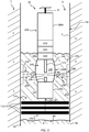
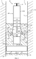
- FIG. 1 describes an exemplary embodiment of an electrical discharge generating device 10 according to the invention.
- the electrical discharge generating device 10 is configured for generating electrical discharges that propagate shock waves 200, in particular for cleaning an equipment arranged in the wellbore 5 in order to improve the recovery of formation fluids and/or gases.
- the electrical discharge generating device 10 constitutes a source of electrohydraulic energy that can be arranged into the wellbore 5 near (i.e. next to) a part 7A of the casing 7 that needs cleaning, for example to remove deposits.
- the electrical discharge generating device 10 is coupled to a wireline 12 which is operable to raise and lower said electrical discharge generating device 10 and to supply power from the surface to said electrical discharge generating device 10.
- a voltage source located external of the wellbore 5 and an electrical circuit (not shown) mounted within said wireline 12 allow to connect said voltage source to the electrical discharge generating device 10. Electrical power is supplied by the low voltage source at a steady and relatively low power from the surface through the wireline 12 to the downhole electrical discharge generating device 10.
- the electrical discharge generating device 10 comprises a cylindrically-shaped body 100 connected to the wireline 12.
- the body 100 comprises a top part 100A, an intermediate part 100B and a bottom part 100C.
- the electrical discharge generating device 10 comprises a power conversion unit 110, a power storage unit 120, a control unit 130, mounted inside the top part 100A of the body 100, and a discharge unit 140 located in the intermediate part 100B of the body 100.
- the power storage unit 120 comprises a plurality of capacitors (not represented) for storage of electrical energy that allows the discharge unit 140 to generate one or a plurality of electrical discharges.
- the power conversion unit 110 comprises suitable circuitry for charging capacitors of the power storage unit 120. Timing of the discharge of the energy from the power storage unit 120 through the discharge unit 140 is controlled by the control unit 130.
- the control unit 130 is a switch, which discharges when the voltage reaches a predefined threshold.
- the discharge unit 140 comprises a first electrode 142, mounted on the bottom of the top part 100A, and a second electrode 144, mounted on the top of the bottom part 100C, configured for triggering an electrical discharge.
- the discharge unit 140 may be configured to propagate shock waves radially or in a predetermined direction.
- electrohydraulic shock waves 200 are generated as shown on FIGS. 2 to 4 . According to the electrohydraulic effect, an electrical discharge is discharged in a very short time (few micro seconds).
- the discharge unit 140 further comprises a membrane 146 delimiting a chamber 148 (illustrated on FIG. 1 ) which is filled with a shock wave internal transmitting liquid 149, allowing transmitting shock waves through the membrane 146 toward the casing 7.
- the discharge unit 140 may not comprise any membrane 146.
- Such membrane 146 isolates the discharge unit 140 from the wellbore 5 while maintaining acoustic coupling with said wellbore 5, improving the propagation of shockwaves while preventing external fluids from the wellbore 5 from damaging the discharge unit 140.
- the membrane 146 is flexible in order to an efficient propagation of shock waves in many directions and prevent shock waves to bounce on it, allowing therefore an efficient conduction of the shock wave toward a metal patch to be sealed on the casing 7.
- the membrane 146 may be made of fluorine rubber or fluoroelastomer with a relative elongation of at least 150 %, preferably at least 200 % and being operable between -35°C and 250°C.
- Other designs of discharge unit 140 are disclosed in US patent 6,227,293 issued to Huffman which is included hereby reference.
- the electrical discharge generating device 10 also comprises a retaining module 150-1, 150-2, 150-3 mounted under the bottom part 100C of the body 100.
- the retaining module 150-1, 150-2, 150-3 is configured for retaining a volume of liquid in order to immerse the discharge unit 140.
- the retaining module 150-1, 150-2, 150-3 allows creating, at least temporarily, a column of external transmitting liquid 152, as illustrated on FIGS. 2 to 4 , for immersing the discharge unit 140, enabling therefore an efficient use of said discharge unit 140 to remove deposits from the parts 7A of the casing 7 which are arranged above the wellbore liquid level 6A.
- the retaining module 150-1, 150-2, 150-3 acts at least partially as a seal, which is not necessarily fully waterproof, in order to block some liquid that is added from the top of the electrical discharge generating device 10 for the duration of the cleaning of the wellbore equipment (i.e. the parts 7A here) as described hereafter.
- the retaining module 150-1, 150-2, 150-3 is mounted on the bottom part 100C of the body 100 of the electrical discharge generating device 10 and defines the bottom limit of an open volume 154, the sides of said volume 154 being defined by the casing 7 (or the production tubing or the wall 5A of the wellbore 5).
- the element to clean i.e. to remove the deposits from lies in the defined volume 154: in this example, some parts 7A of the casing 7 that comprise deposits to remove.
- the retaining module 150-1, 150-2, 150-3 may have different shapes and dimensions.
- the retaining module 150-1 is in the shape of a cone 150-1A, whose vertex points downwards and which is mounted to the bottom part 100C using a rod 150-1B extending vertically from the bottom part 100C below the body 100.
- the retaining module 150-1 optionally comprises an annular element 150-1C for sealing the interface between the cone 150-1A and the part 7A of the casing 7.
- the retaining module 150-2 comprises a plurality of superimposed retaining rings 150-2A (or disks) mounted on a shaft 150-2B (or a rod) extending vertically below the bottom part 100C.
- the retaining module 150-3 comprises an inflatable element 150-3A attached to the bottom part 100C via a rod 150-3B.
- the retaining module could be the bottom part 100C of the body 100 of the device 10 which would be shaped adequately, for example like an inverted cone, a plurality of rings or an inflatable element.
- the electrical discharge generating device 10 is first positioned, in step S1, inside a dry part 7B of the casing 7 that needs cleaning.
- the retaining module 150-1, 150-2, 150-3 seals at least partially the interface between said retaining module 150-1, 150-2, 150-3 and the target part 7A of the casing 7 (i.e. the part 7A to be cleaned).
- Liquid is thus filled from the surface in the wellbore 5 in a step S2 until the discharge unit 140 and the target part 7A are immersed in said liquid, called “external transmitting liquid", for allowing an electrical discharge to be transmitting in said external transmitting liquid upto said immersed target part 7A.
- external transmitting liquid for allowing an electrical discharge to be transmitting in said external transmitting liquid upto said immersed target part 7A.
- step S3 at least one shock wave 200, preferably a series of several shock waves 200 (for example propagated at a periodic interval of time, e.g. every 5 to 20 seconds), is generated into the internal transmitting liquid by the discharge unit 140.
- This at least one shock wave 200 propagates in a step S4 through the membrane 146 and the external transmitting liquid toward the target part 7A of the casing 7.
- a step S5 the at least one propagated shock wave 200 reaches the immersed part 7A of the body 7 and clean said immersed part 7A (for example remove the deposits attached to said part 7A).
- a plurality of series may be advantageously repeated towards the part 7A at different heights to efficiently clean said part 7A and improve the recovery of oil or gas and the stimulation of the wellbore 5.
- the electrical discharge generating device 10 may then be moved, in step S6, to another position inside the wellbore 5 in order to clean another part 7A of the casing 7 or another equipment of the wellbore such as e.g. a production tubing or a well production equipment.
- Embodiments include many additional standard components or equipment that enables and makes operable the described device, process, method and system. Operation, control and performance of portions of or entire steps of a process or method can occur through human interaction, pre-programmed computer control and response systems, or combinations thereof.
- the method according to the invention is not limited to a casing 7 and may be used to remove deposits on various different wellbore equipment installed above the wellbore liquid level 6A such as e.g. a sand control screen, a slotted liner, a perforated liner, a valve, a port, etc.
- the method according to the invention is not limited to a production wellbore and may be used into an abandoned wellbore or an injection wellbore such as a chemical or vapor injection wellbore.
- the invention is not limited to the described embodiment and can be applied to all type of formation fluids or gases transportation means.
Landscapes
- Life Sciences & Earth Sciences (AREA)
- Engineering & Computer Science (AREA)
- Geology (AREA)
- Mining & Mineral Resources (AREA)
- Physics & Mathematics (AREA)
- Environmental & Geological Engineering (AREA)
- Fluid Mechanics (AREA)
- General Life Sciences & Earth Sciences (AREA)
- Geochemistry & Mineralogy (AREA)
- Cleaning By Liquid Or Steam (AREA)
Claims (15)
- Eine elektrische Entladung erzeugende Vorrichtung (10) zum Reinigen einer Ausrüstung (7), die in einem Bohrloch (5) einer unterirdischen Struktur (1) angeordnet ist, um die Rückgewinnung von Strukturfluiden und / oder -gasen zu verbessern, wobei die genannte, eine elektrische Entladung erzeugende Vorrichtung (10) eine Entladungseinheit (140) zum Erzeugen wenigstens einer elektrischen Entladung umfasst, die wenigstens eine Druckwelle (200) zum Reinigen der genannten Ausrüstung (7) verbreitet, dadurch gekennzeichnet, dass die genannte, eine elektrische Entladung erzeugende Vorrichtung (10) weiterhin ein Rückhaltemodul (150-1, 150-2, 150-3) umfasst, das zum Zurückhalten eines Volumens einer Flüssigkeit ausgestaltet ist, um die Entladungseinheit (140) einzutauchen.
- Vorrichtung (10) gemäß Anspruch 1, wobei das Rückhaltemodul (150-1, 150-2, 150-3) ein Rückhalteelement (150-1A, 150-2A, 150-3A) umfasst, das zum Zurückhalten einer Flüssigkeit ausgestaltet ist, um die Entladungseinheit (140) einzutauchen, wenn sie in einem Bohrloch angeordnet ist.
- Vorrichtung (10) gemäß Anspruch 2, wobei das Rückhalteelement (150-1A, 150-2A, 150-3A) aus Plastik hergestellt ist.
- Vorrichtung (10) gemäß irgendeinem der Ansprüche 2 bis 3, wobei das Rückhalteelement (150-1A, 150-2A, 150-3A) am unteren Teil (100C) des Körpers (100) der Vorrichtung (10) befestigt ist.
- Vorrichtung (10) gemäß irgendeinem der Ansprüche 2 bis 4, wobei das Rückhalteelement (150-1A, 150-2A, 150-3A) am unteren Teil (100C) des Körpers (100) der Vorrichtung (10) über eine Stange oder eine Welle (150-1B, 150-2B, 150-3B) befestigt ist.
- Vorrichtung (10) gemäß irgendeinem der Ansprüche 2 bis 5, wobei das Rückhalteelement ein Konus (150-1A) ist, dessen Scheitelpunkt abwärts zeigt, sich unter dem unteren Teil (100C) des Körpers (100) der Vorrichtung (10) erstreckt und ausgestaltet ist, um eine Flüssigkeit zurückzuhalten, um die Entladungseinheit (140) einzutauchen, wenn sie in einem Bohrloch (5) angeordnet ist.
- Vorrichtung (10) gemäß irgendeinem der Ansprüche 2 bis 5, wobei das Rückhalteelement eine Vielzahl von Ringen (150-2A) umfasst, die zum Zurückhalten einer Flüssigkeit ausgestaltet sind, um die Entladungseinheit (140) einzutauchen, wenn sie in einem Bohrloch (5) angeordnet ist.
- Vorrichtung (10) gemäß irgendeinem der Ansprüche 2 bis 5, wobei das Rückhalteelement ein aufblasbares Element (150-3A) ist, das sich vom unteren Teil (100C) des Körpers (100) erstreckt und ausgestaltet ist, um eine Flüssigkeit zurückzuhalten, um die Entladungseinheit (140) einzutauchen, wenn sie in einem Bohrloch (5) angeordnet ist.
- Vorrichtung (10) gemäß Anspruch 1, wobei die genannte, eine elektrische Entladung erzeugende Vorrichtung (10) einen Körper umfasst und der genannte Körper einen unteren Teil umfasst, wobei der genannte untere Teil derart geformt ist, dass er eine Flüssigkeit zurückhält, um die Entladungseinheit einzutauchen, wenn sie in einem Bohrloch eingetaucht ist.
- Vorrichtung (10) gemäß dem voranstehenden Anspruch, bei der der untere Teil aus einem Plastik hergestellt ist.
- Vorrichtung (10) gemäß Anspruch 9, wobei der untere Teil aus einem Metallmaterial hergestellt sein kann.
- Vorrichtung (10) gemäß irgendeinem der Ansprüche 9 bis 11, wobei der untere Teil einen konisch geformten Abschnitt umfasst, dessen Scheitelpunkt abwärts zeigt und ausgestaltet ist, um eine Flüssigkeit zurückzuhalten, um die Entladungseinheit einzutauchen, wenn sie in einem Bohrloch angeordnet ist.
- Vorrichtung (10) gemäß irgendeinem der Ansprüche 9 bis 11, wobei der untere Teil eine Vielzahl von Ringen umfasst, die zum Zurückhalten einer Flüssigkeit ausgestaltet sind, um die Entladungseinheit einzutauchen, wenn sie in einem Bohrloch angeordnet ist.
- Vorrichtung (10) gemäß irgendeinem der Ansprüche 9 bis 11, wobei der untere Teil ein aufblasbares Element umfasst, das zum Zurückhalten einer Flüssigkeit ausgestaltet ist, um die Entladungseinheit einzutauchen, wenn sie in einem Bohrloch angeordnet ist.
- Verfahren zum Reinigen einer Ausrüstung (7), die in einem Bohrloch (5) einer unterirdischen Struktur (1) angeordnet ist, das eine eine elektrische Entladung erzeugende Vorrichtung (10) verwendet, um das Zurückgewinnen von Strukturfluiden und / oder -gasen zu verbessern, wobei die genannte, eine elektrische Entladung erzeugende Vorrichtung (10) eine Entladungseinheit (140) zum Erzeugen wenigstens einer elektrischen Entladung umfasst, die wenigstens eine Druckwelle (200) zum Reinigen der genannten Ausrüstung (7) verbreitet, wobei die Vorrichtung (10) ein Rückhaltemodul (150-1, 150-2, 150-3) umfasst, das zum Zurückhalten eines Volumens einer Flüssigkeit ausgestaltet ist, um die Entladungseinheit (140) einzutauchen, das Verfahren die Anordnungsschritte (S1) der Vorrichtung (10) in der Nähe einer Bohrlochausrüstung (7), das Füllen (S2) einer Flüssigkeit in das Bohrloch (5) derart, dass das Rückhaltemodul (150-1, 150-2, 150-3) ein Volumen einer Flüssigkeit (152) zurückhält, um die Entladungseinheit (140) einzutauchen und das Erzeugen (S3) wenigstens einer elektrischen Entladung in die genannte zurückgehaltene Flüssigkeit (152), die wenigstens eine Druckwelle (200) zum Reinigen (S5) der genannten Ausrüstung (7) verbreitet (S4), umfasst.
Priority Applications (1)
| Application Number | Priority Date | Filing Date | Title |
|---|---|---|---|
| EP17194430.9A EP3461990B1 (de) | 2017-10-02 | 2017-10-02 | Vorrichtung und verfahren zur reinigung von bohrlochausrüstung |
Applications Claiming Priority (1)
| Application Number | Priority Date | Filing Date | Title |
|---|---|---|---|
| EP17194430.9A EP3461990B1 (de) | 2017-10-02 | 2017-10-02 | Vorrichtung und verfahren zur reinigung von bohrlochausrüstung |
Publications (2)
| Publication Number | Publication Date |
|---|---|
| EP3461990A1 EP3461990A1 (de) | 2019-04-03 |
| EP3461990B1 true EP3461990B1 (de) | 2020-04-22 |
Family
ID=60009522
Family Applications (1)
| Application Number | Title | Priority Date | Filing Date |
|---|---|---|---|
| EP17194430.9A Active EP3461990B1 (de) | 2017-10-02 | 2017-10-02 | Vorrichtung und verfahren zur reinigung von bohrlochausrüstung |
Country Status (1)
| Country | Link |
|---|---|
| EP (1) | EP3461990B1 (de) |
Family Cites Families (6)
| Publication number | Priority date | Publication date | Assignee | Title |
|---|---|---|---|---|
| US3760878A (en) * | 1972-03-16 | 1973-09-25 | Amoco Prod Co | Perforations washing tool |
| US4345650A (en) | 1980-04-11 | 1982-08-24 | Wesley Richard H | Process and apparatus for electrohydraulic recovery of crude oil |
| US6227293B1 (en) | 2000-02-09 | 2001-05-08 | Conoco Inc. | Process and apparatus for coupled electromagnetic and acoustic stimulation of crude oil reservoirs using pulsed power electrohydraulic and electromagnetic discharge |
| US20130161007A1 (en) * | 2011-12-22 | 2013-06-27 | General Electric Company | Pulse detonation tool, method and system for formation fracturing |
| EP2940245B1 (de) * | 2014-04-28 | 2023-09-20 | Blue Spark Energy Inc. | Verfahren und Vorrichtung zur Stimulierung einer Behandlungszone in der Nähe eines Bohrlochbereich einer unterirdischen Formation |
| EP2977545B1 (de) * | 2014-07-24 | 2019-06-05 | Blue Spark Energy Inc. | Verfahren und Vorrichtung zur Reinigung von Kontrollpartikeln in einem Bohrloch |
-
2017
- 2017-10-02 EP EP17194430.9A patent/EP3461990B1/de active Active
Non-Patent Citations (1)
| Title |
|---|
| None * |
Also Published As
| Publication number | Publication date |
|---|---|
| EP3461990A1 (de) | 2019-04-03 |
Similar Documents
| Publication | Publication Date | Title |
|---|---|---|
| CA2833992C (en) | Method of controlling a failed well with a ported packer | |
| US9810041B2 (en) | Method and device for cleaning control particles in a wellbore | |
| US9890613B2 (en) | Method and device for removing deposits from a formation fluid or gas transportation means | |
| US8272437B2 (en) | Enhanced geothermal systems and reservoir optimization | |
| US10865622B2 (en) | Device and method for cleaning a wellbore equipment | |
| MX2009002101A (es) | Metodos para fracturar una formacion subterranea utilizando una herramienta de chorro y un fluido tensioactivo biscoelastico para reducir al minimo el daño en la formacion. | |
| CA2769935C (en) | Method and system for cleaning fracture ports | |
| RU2600249C1 (ru) | Способ и устройство воздействия на нефтенасыщенные пласты и призабойную зону горизонтальной скважины | |
| EP2977545B1 (de) | Verfahren und Vorrichtung zur Reinigung von Kontrollpartikeln in einem Bohrloch | |
| EP2940244B1 (de) | Verfahren und Vorrichtung zum Entfernen von Ablagerungen aus einem Formationsflüssigkeits- oder Gastransportmittel | |
| US11859483B2 (en) | Selective overbalanced perforation and injection | |
| EP3461990A1 (de) | Vorrichtung und verfahren zur reinigung von bohrlochausrüstung | |
| US10920516B2 (en) | Device and method for collecting debris of deposits in a wellbore | |
| CA2930355C (en) | Method for sealing an opening of a wellbore equipment | |
| CA3017486A1 (en) | Treatment isolation in restimulations with inner wellbore casing | |
| CN119195720A (zh) | 一种储层内原位气体压裂方法 | |
| EP2940245B1 (de) | Verfahren und Vorrichtung zur Stimulierung einer Behandlungszone in der Nähe eines Bohrlochbereich einer unterirdischen Formation | |
| RU2543004C1 (ru) | Способ кислотного продольно-щелевого гидравлического разрыва низкопроницаемого терригенного коллектора | |
| EP3098379B1 (de) | Verfahren zur abdichtung einer öffnung einer bohrlochausrüstung | |
| CA3201983C (en) | Selective overbalanced perforation and injection | |
| EP3546694A1 (de) | Vorrichtung und verfahren zum sammeln von ablagerungen von ablagerungen in einem bohrloch | |
| Ghetiu et al. | Aspects of New Stimulation Technology of Oil Wells | |
| López–Bonetti et al. | Hydraulic fracture assisted with coiled tubing in unconventional wells: lessons learned and case histories from northern Mexico |
Legal Events
| Date | Code | Title | Description |
|---|---|---|---|
| PUAI | Public reference made under article 153(3) epc to a published international application that has entered the european phase |
Free format text: ORIGINAL CODE: 0009012 |
|
| STAA | Information on the status of an ep patent application or granted ep patent |
Free format text: STATUS: THE APPLICATION HAS BEEN PUBLISHED |
|
| AK | Designated contracting states |
Kind code of ref document: A1 Designated state(s): AL AT BE BG CH CY CZ DE DK EE ES FI FR GB GR HR HU IE IS IT LI LT LU LV MC MK MT NL NO PL PT RO RS SE SI SK SM TR |
|
| AX | Request for extension of the european patent |
Extension state: BA ME |
|
| STAA | Information on the status of an ep patent application or granted ep patent |
Free format text: STATUS: REQUEST FOR EXAMINATION WAS MADE |
|
| 17P | Request for examination filed |
Effective date: 20190729 |
|
| RBV | Designated contracting states (corrected) |
Designated state(s): AL AT BE BG CH CY CZ DE DK EE ES FI FR GB GR HR HU IE IS IT LI LT LU LV MC MK MT NL NO PL PT RO RS SE SI SK SM TR |
|
| GRAP | Despatch of communication of intention to grant a patent |
Free format text: ORIGINAL CODE: EPIDOSNIGR1 |
|
| STAA | Information on the status of an ep patent application or granted ep patent |
Free format text: STATUS: GRANT OF PATENT IS INTENDED |
|
| RIC1 | Information provided on ipc code assigned before grant |
Ipc: E21B 37/00 20060101ALI20191121BHEP Ipc: B08B 7/02 20060101ALI20191121BHEP Ipc: E21B 37/08 20060101ALI20191121BHEP Ipc: E21B 33/12 20060101AFI20191121BHEP |
|
| INTG | Intention to grant announced |
Effective date: 20191216 |
|
| GRAS | Grant fee paid |
Free format text: ORIGINAL CODE: EPIDOSNIGR3 |
|
| GRAA | (expected) grant |
Free format text: ORIGINAL CODE: 0009210 |
|
| STAA | Information on the status of an ep patent application or granted ep patent |
Free format text: STATUS: THE PATENT HAS BEEN GRANTED |
|
| AK | Designated contracting states |
Kind code of ref document: B1 Designated state(s): AL AT BE BG CH CY CZ DE DK EE ES FI FR GB GR HR HU IE IS IT LI LT LU LV MC MK MT NL NO PL PT RO RS SE SI SK SM TR |
|
| REG | Reference to a national code |
Ref country code: CH Ref legal event code: EP |
|
| REG | Reference to a national code |
Ref country code: DE Ref legal event code: R096 Ref document number: 602017015097 Country of ref document: DE |
|
| REG | Reference to a national code |
Ref country code: IE Ref legal event code: FG4D |
|
| REG | Reference to a national code |
Ref country code: AT Ref legal event code: REF Ref document number: 1260303 Country of ref document: AT Kind code of ref document: T Effective date: 20200515 |
|
| REG | Reference to a national code |
Ref country code: NO Ref legal event code: T2 Effective date: 20200422 |
|
| REG | Reference to a national code |
Ref country code: LT Ref legal event code: MG4D |
|
| REG | Reference to a national code |
Ref country code: NL Ref legal event code: MP Effective date: 20200422 |
|
| PG25 | Lapsed in a contracting state [announced via postgrant information from national office to epo] |
Ref country code: LT Free format text: LAPSE BECAUSE OF FAILURE TO SUBMIT A TRANSLATION OF THE DESCRIPTION OR TO PAY THE FEE WITHIN THE PRESCRIBED TIME-LIMIT Effective date: 20200422 Ref country code: SE Free format text: LAPSE BECAUSE OF FAILURE TO SUBMIT A TRANSLATION OF THE DESCRIPTION OR TO PAY THE FEE WITHIN THE PRESCRIBED TIME-LIMIT Effective date: 20200422 Ref country code: PT Free format text: LAPSE BECAUSE OF FAILURE TO SUBMIT A TRANSLATION OF THE DESCRIPTION OR TO PAY THE FEE WITHIN THE PRESCRIBED TIME-LIMIT Effective date: 20200824 Ref country code: NL Free format text: LAPSE BECAUSE OF FAILURE TO SUBMIT A TRANSLATION OF THE DESCRIPTION OR TO PAY THE FEE WITHIN THE PRESCRIBED TIME-LIMIT Effective date: 20200422 Ref country code: FI Free format text: LAPSE BECAUSE OF FAILURE TO SUBMIT A TRANSLATION OF THE DESCRIPTION OR TO PAY THE FEE WITHIN THE PRESCRIBED TIME-LIMIT Effective date: 20200422 Ref country code: IS Free format text: LAPSE BECAUSE OF FAILURE TO SUBMIT A TRANSLATION OF THE DESCRIPTION OR TO PAY THE FEE WITHIN THE PRESCRIBED TIME-LIMIT Effective date: 20200822 Ref country code: GR Free format text: LAPSE BECAUSE OF FAILURE TO SUBMIT A TRANSLATION OF THE DESCRIPTION OR TO PAY THE FEE WITHIN THE PRESCRIBED TIME-LIMIT Effective date: 20200723 |
|
| REG | Reference to a national code |
Ref country code: AT Ref legal event code: MK05 Ref document number: 1260303 Country of ref document: AT Kind code of ref document: T Effective date: 20200422 |
|
| PG25 | Lapsed in a contracting state [announced via postgrant information from national office to epo] |
Ref country code: LV Free format text: LAPSE BECAUSE OF FAILURE TO SUBMIT A TRANSLATION OF THE DESCRIPTION OR TO PAY THE FEE WITHIN THE PRESCRIBED TIME-LIMIT Effective date: 20200422 Ref country code: RS Free format text: LAPSE BECAUSE OF FAILURE TO SUBMIT A TRANSLATION OF THE DESCRIPTION OR TO PAY THE FEE WITHIN THE PRESCRIBED TIME-LIMIT Effective date: 20200422 Ref country code: BG Free format text: LAPSE BECAUSE OF FAILURE TO SUBMIT A TRANSLATION OF THE DESCRIPTION OR TO PAY THE FEE WITHIN THE PRESCRIBED TIME-LIMIT Effective date: 20200722 Ref country code: HR Free format text: LAPSE BECAUSE OF FAILURE TO SUBMIT A TRANSLATION OF THE DESCRIPTION OR TO PAY THE FEE WITHIN THE PRESCRIBED TIME-LIMIT Effective date: 20200422 |
|
| PG25 | Lapsed in a contracting state [announced via postgrant information from national office to epo] |
Ref country code: AL Free format text: LAPSE BECAUSE OF FAILURE TO SUBMIT A TRANSLATION OF THE DESCRIPTION OR TO PAY THE FEE WITHIN THE PRESCRIBED TIME-LIMIT Effective date: 20200422 |
|
| REG | Reference to a national code |
Ref country code: DE Ref legal event code: R097 Ref document number: 602017015097 Country of ref document: DE |
|
| PG25 | Lapsed in a contracting state [announced via postgrant information from national office to epo] |
Ref country code: CZ Free format text: LAPSE BECAUSE OF FAILURE TO SUBMIT A TRANSLATION OF THE DESCRIPTION OR TO PAY THE FEE WITHIN THE PRESCRIBED TIME-LIMIT Effective date: 20200422 Ref country code: RO Free format text: LAPSE BECAUSE OF FAILURE TO SUBMIT A TRANSLATION OF THE DESCRIPTION OR TO PAY THE FEE WITHIN THE PRESCRIBED TIME-LIMIT Effective date: 20200422 Ref country code: SM Free format text: LAPSE BECAUSE OF FAILURE TO SUBMIT A TRANSLATION OF THE DESCRIPTION OR TO PAY THE FEE WITHIN THE PRESCRIBED TIME-LIMIT Effective date: 20200422 Ref country code: IT Free format text: LAPSE BECAUSE OF FAILURE TO SUBMIT A TRANSLATION OF THE DESCRIPTION OR TO PAY THE FEE WITHIN THE PRESCRIBED TIME-LIMIT Effective date: 20200422 Ref country code: EE Free format text: LAPSE BECAUSE OF FAILURE TO SUBMIT A TRANSLATION OF THE DESCRIPTION OR TO PAY THE FEE WITHIN THE PRESCRIBED TIME-LIMIT Effective date: 20200422 Ref country code: AT Free format text: LAPSE BECAUSE OF FAILURE TO SUBMIT A TRANSLATION OF THE DESCRIPTION OR TO PAY THE FEE WITHIN THE PRESCRIBED TIME-LIMIT Effective date: 20200422 Ref country code: DK Free format text: LAPSE BECAUSE OF FAILURE TO SUBMIT A TRANSLATION OF THE DESCRIPTION OR TO PAY THE FEE WITHIN THE PRESCRIBED TIME-LIMIT Effective date: 20200422 Ref country code: ES Free format text: LAPSE BECAUSE OF FAILURE TO SUBMIT A TRANSLATION OF THE DESCRIPTION OR TO PAY THE FEE WITHIN THE PRESCRIBED TIME-LIMIT Effective date: 20200422 |
|
| PG25 | Lapsed in a contracting state [announced via postgrant information from national office to epo] |
Ref country code: SK Free format text: LAPSE BECAUSE OF FAILURE TO SUBMIT A TRANSLATION OF THE DESCRIPTION OR TO PAY THE FEE WITHIN THE PRESCRIBED TIME-LIMIT Effective date: 20200422 Ref country code: PL Free format text: LAPSE BECAUSE OF FAILURE TO SUBMIT A TRANSLATION OF THE DESCRIPTION OR TO PAY THE FEE WITHIN THE PRESCRIBED TIME-LIMIT Effective date: 20200422 |
|
| PLBE | No opposition filed within time limit |
Free format text: ORIGINAL CODE: 0009261 |
|
| STAA | Information on the status of an ep patent application or granted ep patent |
Free format text: STATUS: NO OPPOSITION FILED WITHIN TIME LIMIT |
|
| 26N | No opposition filed |
Effective date: 20210125 |
|
| REG | Reference to a national code |
Ref country code: DE Ref legal event code: R119 Ref document number: 602017015097 Country of ref document: DE |
|
| PG25 | Lapsed in a contracting state [announced via postgrant information from national office to epo] |
Ref country code: SI Free format text: LAPSE BECAUSE OF FAILURE TO SUBMIT A TRANSLATION OF THE DESCRIPTION OR TO PAY THE FEE WITHIN THE PRESCRIBED TIME-LIMIT Effective date: 20200422 |
|
| REG | Reference to a national code |
Ref country code: CH Ref legal event code: PL |
|
| PG25 | Lapsed in a contracting state [announced via postgrant information from national office to epo] |
Ref country code: LU Free format text: LAPSE BECAUSE OF NON-PAYMENT OF DUE FEES Effective date: 20201002 Ref country code: MC Free format text: LAPSE BECAUSE OF FAILURE TO SUBMIT A TRANSLATION OF THE DESCRIPTION OR TO PAY THE FEE WITHIN THE PRESCRIBED TIME-LIMIT Effective date: 20200422 |
|
| REG | Reference to a national code |
Ref country code: BE Ref legal event code: MM Effective date: 20201031 |
|
| PG25 | Lapsed in a contracting state [announced via postgrant information from national office to epo] |
Ref country code: DE Free format text: LAPSE BECAUSE OF NON-PAYMENT OF DUE FEES Effective date: 20210501 |
|
| PG25 | Lapsed in a contracting state [announced via postgrant information from national office to epo] |
Ref country code: BE Free format text: LAPSE BECAUSE OF NON-PAYMENT OF DUE FEES Effective date: 20201031 Ref country code: CH Free format text: LAPSE BECAUSE OF NON-PAYMENT OF DUE FEES Effective date: 20201031 Ref country code: LI Free format text: LAPSE BECAUSE OF NON-PAYMENT OF DUE FEES Effective date: 20201031 |
|
| PG25 | Lapsed in a contracting state [announced via postgrant information from national office to epo] |
Ref country code: IE Free format text: LAPSE BECAUSE OF NON-PAYMENT OF DUE FEES Effective date: 20201002 |
|
| PG25 | Lapsed in a contracting state [announced via postgrant information from national office to epo] |
Ref country code: TR Free format text: LAPSE BECAUSE OF FAILURE TO SUBMIT A TRANSLATION OF THE DESCRIPTION OR TO PAY THE FEE WITHIN THE PRESCRIBED TIME-LIMIT Effective date: 20200422 Ref country code: MT Free format text: LAPSE BECAUSE OF FAILURE TO SUBMIT A TRANSLATION OF THE DESCRIPTION OR TO PAY THE FEE WITHIN THE PRESCRIBED TIME-LIMIT Effective date: 20200422 Ref country code: CY Free format text: LAPSE BECAUSE OF FAILURE TO SUBMIT A TRANSLATION OF THE DESCRIPTION OR TO PAY THE FEE WITHIN THE PRESCRIBED TIME-LIMIT Effective date: 20200422 |
|
| PG25 | Lapsed in a contracting state [announced via postgrant information from national office to epo] |
Ref country code: MK Free format text: LAPSE BECAUSE OF FAILURE TO SUBMIT A TRANSLATION OF THE DESCRIPTION OR TO PAY THE FEE WITHIN THE PRESCRIBED TIME-LIMIT Effective date: 20200422 |
|
| PGFP | Annual fee paid to national office [announced via postgrant information from national office to epo] |
Ref country code: FR Payment date: 20250918 Year of fee payment: 9 |
|
| PGFP | Annual fee paid to national office [announced via postgrant information from national office to epo] |
Ref country code: GB Payment date: 20251024 Year of fee payment: 9 |
|
| PGFP | Annual fee paid to national office [announced via postgrant information from national office to epo] |
Ref country code: NO Payment date: 20251022 Year of fee payment: 9 |