EP3461932A1 - Strut and method of forming strut - Google Patents
Strut and method of forming strut Download PDFInfo
- Publication number
- EP3461932A1 EP3461932A1 EP18194841.5A EP18194841A EP3461932A1 EP 3461932 A1 EP3461932 A1 EP 3461932A1 EP 18194841 A EP18194841 A EP 18194841A EP 3461932 A1 EP3461932 A1 EP 3461932A1
- Authority
- EP
- European Patent Office
- Prior art keywords
- mandrel
- threaded section
- strut
- ring
- internal threaded
- Prior art date
- Legal status (The legal status is an assumption and is not a legal conclusion. Google has not performed a legal analysis and makes no representation as to the accuracy of the status listed.)
- Granted
Links
- 0 C*1**c(C=C)*c1 Chemical compound C*1**c(C=C)*c1 0.000 description 1
Images



Classifications
-
- B—PERFORMING OPERATIONS; TRANSPORTING
- B23—MACHINE TOOLS; METAL-WORKING NOT OTHERWISE PROVIDED FOR
- B23P—METAL-WORKING NOT OTHERWISE PROVIDED FOR; COMBINED OPERATIONS; UNIVERSAL MACHINE TOOLS
- B23P15/00—Making specific metal objects by operations not covered by a single other subclass or a group in this subclass
-
- C—CHEMISTRY; METALLURGY
- C25—ELECTROLYTIC OR ELECTROPHORETIC PROCESSES; APPARATUS THEREFOR
- C25D—PROCESSES FOR THE ELECTROLYTIC OR ELECTROPHORETIC PRODUCTION OF COATINGS; ELECTROFORMING; APPARATUS THEREFOR
- C25D1/00—Electroforming
- C25D1/02—Tubes; Rings; Hollow bodies
-
- B—PERFORMING OPERATIONS; TRANSPORTING
- B21—MECHANICAL METAL-WORKING WITHOUT ESSENTIALLY REMOVING MATERIAL; PUNCHING METAL
- B21D—WORKING OR PROCESSING OF SHEET METAL OR METAL TUBES, RODS OR PROFILES WITHOUT ESSENTIALLY REMOVING MATERIAL; PUNCHING METAL
- B21D22/00—Shaping without cutting, by stamping, spinning, or deep-drawing
- B21D22/20—Deep-drawing
- B21D22/28—Deep-drawing of cylindrical articles using consecutive dies
-
- B—PERFORMING OPERATIONS; TRANSPORTING
- B64—AIRCRAFT; AVIATION; COSMONAUTICS
- B64D—EQUIPMENT FOR FITTING IN OR TO AIRCRAFT; FLIGHT SUITS; PARACHUTES; ARRANGEMENT OR MOUNTING OF POWER PLANTS OR PROPULSION TRANSMISSIONS IN AIRCRAFT
- B64D27/00—Arrangement or mounting of power plants in aircraft; Aircraft characterised by the type or position of power plants
- B64D27/02—Aircraft characterised by the type or position of power plants
- B64D27/10—Aircraft characterised by the type or position of power plants of gas-turbine type
- B64D27/12—Aircraft characterised by the type or position of power plants of gas-turbine type within, or attached to, wings
-
- B—PERFORMING OPERATIONS; TRANSPORTING
- B64—AIRCRAFT; AVIATION; COSMONAUTICS
- B64D—EQUIPMENT FOR FITTING IN OR TO AIRCRAFT; FLIGHT SUITS; PARACHUTES; ARRANGEMENT OR MOUNTING OF POWER PLANTS OR PROPULSION TRANSMISSIONS IN AIRCRAFT
- B64D27/00—Arrangement or mounting of power plants in aircraft; Aircraft characterised by the type or position of power plants
- B64D27/40—Arrangements for mounting power plants in aircraft
- B64D27/402—Arrangements for mounting power plants in aircraft comprising box like supporting frames, e.g. pylons or arrangements for embracing the power plant
-
- C—CHEMISTRY; METALLURGY
- C25—ELECTROLYTIC OR ELECTROPHORETIC PROCESSES; APPARATUS THEREFOR
- C25D—PROCESSES FOR THE ELECTROLYTIC OR ELECTROPHORETIC PRODUCTION OF COATINGS; ELECTROFORMING; APPARATUS THEREFOR
- C25D1/00—Electroforming
-
- F—MECHANICAL ENGINEERING; LIGHTING; HEATING; WEAPONS; BLASTING
- F16—ENGINEERING ELEMENTS AND UNITS; GENERAL MEASURES FOR PRODUCING AND MAINTAINING EFFECTIVE FUNCTIONING OF MACHINES OR INSTALLATIONS; THERMAL INSULATION IN GENERAL
- F16B—DEVICES FOR FASTENING OR SECURING CONSTRUCTIONAL ELEMENTS OR MACHINE PARTS TOGETHER, e.g. NAILS, BOLTS, CIRCLIPS, CLAMPS, CLIPS OR WEDGES; JOINTS OR JOINTING
- F16B37/00—Nuts or like thread-engaging members
- F16B37/04—Devices for fastening nuts to surfaces, e.g. sheets, plates
- F16B37/048—Non-releasable devices
-
- B—PERFORMING OPERATIONS; TRANSPORTING
- B23—MACHINE TOOLS; METAL-WORKING NOT OTHERWISE PROVIDED FOR
- B23K—SOLDERING OR UNSOLDERING; WELDING; CLADDING OR PLATING BY SOLDERING OR WELDING; CUTTING BY APPLYING HEAT LOCALLY, e.g. FLAME CUTTING; WORKING BY LASER BEAM
- B23K31/00—Processes relevant to this subclass, specially adapted for particular articles or purposes, but not covered by any single one of main groups B23K1/00 - B23K28/00
- B23K31/02—Processes relevant to this subclass, specially adapted for particular articles or purposes, but not covered by any single one of main groups B23K1/00 - B23K28/00 relating to soldering or welding
Definitions
- Struts are frequently used in such structures to support components against undesired tension, compression or stresses.
- Aircraft components can experience a large range of forces or stresses across a range of temperatures in operation. It can be beneficial to form a strut capable of being used in a variety of environments, where features of the strut can be tailored to the desired environment in operation.
- a method of forming a strut includes providing a ring having an internal threaded section, coupling a mandrel to the ring having the internal threaded section, electroforming a metallic layer over exposed surfaces of the ring having the internal threaded section and outer surfaces of the mandrel, and removing the mandrel to define the strut having an integral monolithic body with the internal threaded section.
- a method of forming a strut includes providing a ring having an internal threaded section, coupling a metal mandrel to the ring having the internal threaded section, and electroforming a metallic layer over exposed surfaces of the ring having the internal threaded section and outer surfaces of the mandrel to define a strut rod having an integral monolithic body with the internal threaded section.
- a strut assembly for an aircraft includes a strut core having a metallic integral monolithic body that includes a bar having at least one end with an internal threaded section.
- the present disclosure is directed to a strut assembly.
- the present disclosure will be described with respect to a strut within an aircraft engine pylon. It will be understood, however, that the present disclosure is not so limited and can have general applicability throughout the aircraft, as well as in non-aircraft applications or other commercial or residential applications.
- a set can include any number of the respectively described elements, including only one element.
- all directional references e.g., radial, axial, proximal, distal, upper, lower, upward, downward, left, right, lateral, front, back, top, bottom, above, below, vertical, horizontal, clockwise, counterclockwise, upstream, downstream, aft, etc.
- Connection references e.g., attached, coupled, connected, and joined
- connection references are to be construed broadly and can include intermediate members between a collection of elements and relative movement between elements unless otherwise indicated. As such, connection references do not necessarily infer that two elements are directly connected and in fixed relation to one another.
- the exemplary drawings are for purposes of illustration only and the dimensions, positions, order and relative sizes reflected in the drawings attached hereto can vary.
- FIG. 1 illustrates an aircraft 10, which can also include a fuselage 12, a cockpit 14 positioned in the fuselage 12, and wing assemblies 16 extending outward from the fuselage 12.
- the aircraft 10 can also include multiple engines, including turbine engines 18, which by way of non-limiting example can be turbojet engines, turbofan engines, or turboprop engines. While a commercial aircraft 10 has been illustrated, it is contemplated that aspects of the disclosure described herein can be used in any type of aircraft including helicopters or space shuttles.
- turbine engines 18 have been illustrated on each of the wing assemblies 16, it will be understood that any number of turbine engines 18 can be included in the aircraft 10, including, but not limited to, a single turbine engine 18 on the wing assemblies 16 or fuselage 12, a single turbine engine 18 mounted in the fuselage 12 or the vertical tail, or a turbine engine 10 on each wing assembly 16 and another turbine engine 10 on the tail.
- the turbine engine 18 can be secured to the wing assembly 16 by way of an engine pylon 19.
- a strut assembly 20 can be mounted within the engine pylon 19 such that internal forces or stresses can be carried along the strut assembly 20 to support the structure of the aircraft 10. It will be understood that while illustrated within the engine pylon 19, the strut assembly 20 can be included anywhere within the aircraft 10, including within the turbine engine 18, as desired.
- the strut assembly 20 can include a rod or bar 22 with rings 24 having an internal threaded section 24T and integrally formed within distal ends 26 of the bar 22.
- the bar 22 can also include an outer metallic layer or metallic shell 28 and a strut core 30 that can be hollow or solid. Together the bar 22 and rings 24 can define an integral monolithic body 32 of the strut assembly 20.
- the strut assembly 20 can be formed from any suitable material for the desired environment such as aluminum, titanium, or steel, in non-limiting examples.
- FIG. 3 more clearly illustrates that strut end fittings 34 having an external threaded section 34T can be attached to the rings 24 for attachment within a mechanical assembly such as the aircraft 10 of FIG. 1 .
- the internal threaded section 24T of the ring 24 can couple to the external threaded section 34T on the end fitting 34 for secure attachment, and the outer metallic layer 28 can surround the ring 24 and threaded portion 34T of the end fitting 34.
- a mandrel 40A is illustrated having mandrel ends 42 with a ring 24 placed around each mandrel end 42; it should be understood that one end 42 of the mandrel 40A is shown, and the description of one end 42 can apply to either or both ends 42.
- the mandrel 40A can be molded from a sacrificial material such as wax or plastic material, for example by injection molding, where the mandrel 40A can be attached to the rings 24 during the molding process.
- the electroforming process can create the metallic layer 28 over the rings 24 and mandrel 40A as shown in FIG.
- the strut assembly 20 can be created with the metallic layer 28 forming a hollow strut core 30, and rings 24 with internal threading 24T disposed within the distal ends 26, as illustrated in FIG. 6 .
- An exemplary bath tank 50 carries a single metal constituent solution 52.
- the single metal constituent solution 52 in one non-limiting example, can include aluminum alloy carrying manganese ions. In one alternative, non-limiting example, the single metal constituent solution 52 can include nickel alloy carrying alloying metal ions.
- An anode 54 spaced from a cathode 62 is provided in the bath tank 50.
- the anodes 54 can be sacrificial anodes or an inert anode. While one anode is shown, it should be understood that the bath tank 50 can include any number of anodes 54 as desired.
- the strut assembly 20 can form the cathode 62, having electrically conductive material. It is also contemplated that a conductive spray or similar treatment can be provided to the strut assembly 20 to facilitate formation of the cathode 62. In addition, while illustrated as one cathode 62, it should be appreciated that one or more cathodes are contemplated for use in the bath tank 50.
- a controller 64 which can include a power supply, can electrically couple to the anode 54 and the cathode 62 by electrical conduits 66 to form a circuit via the conductive metal constituent solution 52.
- a switch 68 or sub-controller can be included along the electrical conduits 66, between the controller 64 and the anodes 54 and cathode 62.
- a current can be supplied from the anode 54 to the cathode 62 to electro form a monolithic body at the strut assembly 20.
- aluminum and manganese from the single metal constituent solution 52 form a metallic layer, such as the metallic layer 28 described in FIG. 3 , over the strut assembly 20 to form the monolithic body 32.
- the mandrel utilized for forming the strut assembly 20 can be a non-sacrificial component that remains within the strut assembly 20.
- a mandrel 40B can comprise a solid body that the metallic layer 28 is electroformed over along with the rings 24. In this manner the mandrel 40B, rings 24, and metallic layer 28 form a strut core 30 that is an integral monolithic body 32.
- the mandrel 40B by way of non-limiting example can include a solid, cold-drawn aluminum body.
- the rings 24 can be threaded into ends of the mandrel 40B as described above, or the rings 24 can also be coupled to the mandrel 40B by suitable methods such as welding.
- an additional layer 70 can be deposited onto select areas of the metal layer 28, and is illustrated in the example of FIG. 8 as being deposited in registry with the rings 24 to provide additional support to the rings 24 against applied stresses in operation. It will be appreciated that the additional layer 70 can be applied over any selected region of the strut assembly 20 as desired.
- FIG. 9 further illustrates that a hollow mandrel 40C can also be utilized, such that when the metallic layer 28 is electroformed over the mandrel 40C and rings 24, the resulting strut core 30 can be hollow.
- the hollow mandrel 40C can include a cold-drawn aluminum body.
- the rings 24 can be threaded or welded into ends of the hollow mandrel 40C to form the integral monolithic body 32.
- the aspects of the disclosure described above provide for a variety of benefits including that the use of high strength material for electroforming, such as aluminum, can enhance load-carrying capabilities of the strut.
- the method of forming the strut integrally with the internally-threaded rings can eliminate the need for additional features for insertion of traditional locking rings.
- the local deposition of material over regions experiencing locally higher stresses can allow for selective strengthening of regions along the strut thereby offering a weight-effective strut design. This can be done even if the strut itself is not a monolithic strut as described.
- the proposed methods can also enable deposition of tailor-made materials with improved properties such as yield strength or ultimate strength of the material when compared to the use of conventional materials and manufacturing methods.
Landscapes
- Engineering & Computer Science (AREA)
- Chemical & Material Sciences (AREA)
- Mechanical Engineering (AREA)
- Organic Chemistry (AREA)
- Materials Engineering (AREA)
- Metallurgy (AREA)
- Electrochemistry (AREA)
- Chemical Kinetics & Catalysis (AREA)
- General Engineering & Computer Science (AREA)
- Aviation & Aerospace Engineering (AREA)
- Electroplating Methods And Accessories (AREA)
- Ropes Or Cables (AREA)
- Forging (AREA)
Abstract
Description
- Mechanical structures, such as chassis or frames, often experience forces that can cause components within the structure to shift in relative positioning. Struts are frequently used in such structures to support components against undesired tension, compression or stresses.
- Aircraft components can experience a large range of forces or stresses across a range of temperatures in operation. It can be beneficial to form a strut capable of being used in a variety of environments, where features of the strut can be tailored to the desired environment in operation.
- In one aspect, a method of forming a strut includes providing a ring having an internal threaded section, coupling a mandrel to the ring having the internal threaded section, electroforming a metallic layer over exposed surfaces of the ring having the internal threaded section and outer surfaces of the mandrel, and removing the mandrel to define the strut having an integral monolithic body with the internal threaded section.
- In another aspect, a method of forming a strut includes providing a ring having an internal threaded section, coupling a metal mandrel to the ring having the internal threaded section, and electroforming a metallic layer over exposed surfaces of the ring having the internal threaded section and outer surfaces of the mandrel to define a strut rod having an integral monolithic body with the internal threaded section.
- In yet another aspect, a strut assembly for an aircraft includes a strut core having a metallic integral monolithic body that includes a bar having at least one end with an internal threaded section.
- In the drawings:
-
FIG. 1 is a schematic view of an aircraft having a strut in accordance with various aspects described herein. -
FIG. 2 is a cross-sectional view of a strut assembly that can be utilized in the aircraft ofFIG. 1 . -
FIG. 3 is an exploded view of an end of the strut assembly ofFIG. 2 . -
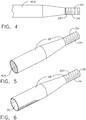
FIG. 4 illustrates a mandrel and ring used to form the strut assembly ofFIG. 2 . -
FIG. 5 illustrates an electroformed coating over elements ofFIG. 4 . -
FIG. 6 illustrates the mandrel removed from that ofFIG. 5 . -
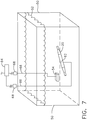
FIG. 7 illustrates an electroforming bath for forming the strut assembly ofFIG. 2 . -
FIG. 8 is a cross-sectional view of a strut assembly that can be utilized in the aircraft ofFIG. 1 . -
FIG. 9 is a cross-sectional view of a strut assembly that can be utilized in the aircraft ofFIG. 1 . - The present disclosure is directed to a strut assembly. For purposes of illustration, the present disclosure will be described with respect to a strut within an aircraft engine pylon. It will be understood, however, that the present disclosure is not so limited and can have general applicability throughout the aircraft, as well as in non-aircraft applications or other commercial or residential applications.
- As used herein "a set" can include any number of the respectively described elements, including only one element. Additionally, all directional references (e.g., radial, axial, proximal, distal, upper, lower, upward, downward, left, right, lateral, front, back, top, bottom, above, below, vertical, horizontal, clockwise, counterclockwise, upstream, downstream, aft, etc.) are only used for identification purposes to aid the reader's understanding of the present disclosure, and do not create limitations, particularly as to the position, orientation, or use of the present disclosure. Connection references (e.g., attached, coupled, connected, and joined) are to be construed broadly and can include intermediate members between a collection of elements and relative movement between elements unless otherwise indicated. As such, connection references do not necessarily infer that two elements are directly connected and in fixed relation to one another. The exemplary drawings are for purposes of illustration only and the dimensions, positions, order and relative sizes reflected in the drawings attached hereto can vary.
-
FIG. 1 illustrates anaircraft 10, which can also include afuselage 12, acockpit 14 positioned in thefuselage 12, andwing assemblies 16 extending outward from thefuselage 12. Theaircraft 10 can also include multiple engines, includingturbine engines 18, which by way of non-limiting example can be turbojet engines, turbofan engines, or turboprop engines. While acommercial aircraft 10 has been illustrated, it is contemplated that aspects of the disclosure described herein can be used in any type of aircraft including helicopters or space shuttles. Further, while twoturbine engines 18 have been illustrated on each of thewing assemblies 16, it will be understood that any number ofturbine engines 18 can be included in theaircraft 10, including, but not limited to, asingle turbine engine 18 on thewing assemblies 16 orfuselage 12, asingle turbine engine 18 mounted in thefuselage 12 or the vertical tail, or aturbine engine 10 on eachwing assembly 16 and anotherturbine engine 10 on the tail. - In the example of
FIG. 1 , theturbine engine 18 can be secured to thewing assembly 16 by way of anengine pylon 19. Astrut assembly 20 can be mounted within theengine pylon 19 such that internal forces or stresses can be carried along thestrut assembly 20 to support the structure of theaircraft 10. It will be understood that while illustrated within theengine pylon 19, thestrut assembly 20 can be included anywhere within theaircraft 10, including within theturbine engine 18, as desired. - Turning to
FIG. 2 , thestrut assembly 20 can include a rod orbar 22 withrings 24 having an internal threadedsection 24T and integrally formed withindistal ends 26 of thebar 22. Thebar 22 can also include an outer metallic layer ormetallic shell 28 and astrut core 30 that can be hollow or solid. Together thebar 22 andrings 24 can define an integralmonolithic body 32 of thestrut assembly 20. Thestrut assembly 20 can be formed from any suitable material for the desired environment such as aluminum, titanium, or steel, in non-limiting examples. -
FIG. 3 more clearly illustrates thatstrut end fittings 34 having an external threadedsection 34T can be attached to therings 24 for attachment within a mechanical assembly such as theaircraft 10 ofFIG. 1 . The internal threadedsection 24T of thering 24 can couple to the external threadedsection 34T on the end fitting 34 for secure attachment, and the outermetallic layer 28 can surround thering 24 and threadedportion 34T of the end fitting 34. - Referring now to
FIG. 4 , amandrel 40A is illustrated havingmandrel ends 42 with aring 24 placed around eachmandrel end 42; it should be understood that oneend 42 of themandrel 40A is shown, and the description of oneend 42 can apply to either or bothends 42. It is contemplated in a non-limiting example that themandrel 40A can be molded from a sacrificial material such as wax or plastic material, for example by injection molding, where themandrel 40A can be attached to therings 24 during the molding process. The electroforming process can create themetallic layer 28 over therings 24 andmandrel 40A as shown inFIG. 5 , where all exposed surfaces of therings 24 andmandrel 40A can be covered by themetallic layer 28. Themandrel 40A can then be removed by application of heat or a chemical flush in non-limiting examples. In this manner, thestrut assembly 20 can be created with themetallic layer 28 forming ahollow strut core 30, andrings 24 withinternal threading 24T disposed within thedistal ends 26, as illustrated inFIG. 6 . - The electroforming process is illustrated by way of an electrodeposition bath in
FIG. 7 . Anexemplary bath tank 50 carries a single metalconstituent solution 52. The singlemetal constituent solution 52, in one non-limiting example, can include aluminum alloy carrying manganese ions. In one alternative, non-limiting example, the singlemetal constituent solution 52 can include nickel alloy carrying alloying metal ions. - An
anode 54 spaced from acathode 62 is provided in thebath tank 50. Theanodes 54 can be sacrificial anodes or an inert anode. While one anode is shown, it should be understood that thebath tank 50 can include any number ofanodes 54 as desired. Thestrut assembly 20 can form thecathode 62, having electrically conductive material. It is also contemplated that a conductive spray or similar treatment can be provided to thestrut assembly 20 to facilitate formation of thecathode 62. In addition, while illustrated as onecathode 62, it should be appreciated that one or more cathodes are contemplated for use in thebath tank 50. - A
controller 64, which can include a power supply, can electrically couple to theanode 54 and thecathode 62 byelectrical conduits 66 to form a circuit via the conductivemetal constituent solution 52. Optionally, aswitch 68 or sub-controller can be included along theelectrical conduits 66, between thecontroller 64 and theanodes 54 andcathode 62. During operation, a current can be supplied from theanode 54 to thecathode 62 to electro form a monolithic body at thestrut assembly 20. During supply of the current, aluminum and manganese from the singlemetal constituent solution 52 form a metallic layer, such as themetallic layer 28 described inFIG. 3 , over thestrut assembly 20 to form themonolithic body 32. - Turning to
FIG. 8 , it is also contemplated that the mandrel utilized for forming thestrut assembly 20 can be a non-sacrificial component that remains within thestrut assembly 20. In one example, a mandrel 40B can comprise a solid body that themetallic layer 28 is electroformed over along with therings 24. In this manner the mandrel 40B,rings 24, andmetallic layer 28 form astrut core 30 that is an integralmonolithic body 32. The mandrel 40B by way of non-limiting example can include a solid, cold-drawn aluminum body. Therings 24 can be threaded into ends of the mandrel 40B as described above, or therings 24 can also be coupled to the mandrel 40B by suitable methods such as welding. - It is further contemplated that an
additional layer 70 can be deposited onto select areas of themetal layer 28, and is illustrated in the example ofFIG. 8 as being deposited in registry with therings 24 to provide additional support to therings 24 against applied stresses in operation. It will be appreciated that theadditional layer 70 can be applied over any selected region of thestrut assembly 20 as desired. -
FIG. 9 further illustrates that a hollow mandrel 40C can also be utilized, such that when themetallic layer 28 is electroformed over the mandrel 40C and rings 24, the resultingstrut core 30 can be hollow. The hollow mandrel 40C can include a cold-drawn aluminum body. As in the example ofFIG. 8 , therings 24 can be threaded or welded into ends of the hollow mandrel 40C to form the integralmonolithic body 32. - The aspects of the disclosure described above provide for a variety of benefits including that the use of high strength material for electroforming, such as aluminum, can enhance load-carrying capabilities of the strut. The method of forming the strut integrally with the internally-threaded rings can eliminate the need for additional features for insertion of traditional locking rings.
- In addition, the local deposition of material over regions experiencing locally higher stresses, such as the threaded regions at the rings where forces can be concentrated in operation, can allow for selective strengthening of regions along the strut thereby offering a weight-effective strut design. This can be done even if the strut itself is not a monolithic strut as described. The proposed methods can also enable deposition of tailor-made materials with improved properties such as yield strength or ultimate strength of the material when compared to the use of conventional materials and manufacturing methods.
- To the extent not already described, the different features and structures of the various embodiments may be used in combination with each other as desired. That one feature may not be illustrated in all of the embodiments and is not meant to be construed that it may not be, but is done for brevity of description. Thus, the various features of the different embodiments may be mixed and matched as desired to form new embodiments, whether or not the new embodiments are expressly described. All combinations or permutations of features described herein are covered by this disclosure.
- This written description uses examples to disclose the invention, including the best mode, and also to enable any person skilled in the art to practice the invention, including making and using any devices or systems and performing any incorporated methods. The patentable scope of the invention is defined by the claims, and may include other examples that occur to those skilled in the art. Such other examples are intended to be within the scope of the claims if they have structural elements that do not differ from the literal language of the claims, or if they include equivalent structural elements with insubstantial differences from the literal languages of the claims.
Claims (15)
- A method of forming a strut, comprising:providing a ring having an internal threaded section;coupling a mandrel to the ring having the internal threaded section;electroforming a metallic layer over exposed surfaces of the ring having the internal threaded section and outer surfaces of the mandrel; andremoving the mandrel to define the strut having an integral monolithic body with the internal threaded section.
- The method of claim 1, wherein the coupling the mandrel to the ring having the internal threaded section includes injection molding the mandrel.
- The method of either of claim 1 or 2, further comprising attaching a strut end fitting within the internal threaded section.
- The method of claim 3, wherein the strut end fitting includes an external threaded section and the attaching comprises threading the external threaded section of the strut end fitting into the internal threaded section of the integral monolithic body.
- The method of any preceding claim, further comprising electroforming an additional layer over the metallic layer on the ring.
- The method of any preceding claim, wherein the mandrel is a sacrificial mandrel made of wax or plastic.
- The method of any preceding claim, wherein two rings are provided and the mandrel is coupled between the two rings.
- A method of forming a strut (20), comprising:providing a ring (24) having an internal threaded section (36);coupling a metal mandrel (40A, 40B, 40C) to the ring having the internal threaded section; andelectroforming a metallic layer (28) over exposed surfaces of the ring (24) having the internal threaded section and outer surfaces of the mandrel to define a strut rod having an integral monolithic body with the internal threaded section.
- The method of claim 8, wherein the metal mandrel is a hollow aluminum mandrel.
- The method of claim 9, wherein the hollow aluminum mandrel includes a threaded section and the ring further includes an external threaded section and the coupling includes threading the hollow aluminum mandrel onto the external threaded section.
- The method of either of claim 9 or 10, wherein the coupling includes welding the hollow aluminum mandrel to the ring.
- The method of any of claims 8 to 11, further comprising drawing a metal body to form the metal mandrel.
- The method of any of claims 8 to 12, further comprising attaching a strut end fitting within the internal threaded section.
- The method of any of claims 8 to 13, further comprising electroforming an additional layer over the metallic layer on the ring.
- The method of any of claims 8 to 14, wherein two rings are provided and the metal mandrel is coupled between the two rings.
Applications Claiming Priority (1)
| Application Number | Priority Date | Filing Date | Title |
|---|---|---|---|
| GB1715614.2A GB2566947B (en) | 2017-09-27 | 2017-09-27 | Strut and method of forming strut |
Publications (2)
| Publication Number | Publication Date |
|---|---|
| EP3461932A1 true EP3461932A1 (en) | 2019-04-03 |
| EP3461932B1 EP3461932B1 (en) | 2020-05-27 |
Family
ID=60244327
Family Applications (1)
| Application Number | Title | Priority Date | Filing Date |
|---|---|---|---|
| EP18194841.5A Active EP3461932B1 (en) | 2017-09-27 | 2018-09-17 | Strut and method of forming strut |
Country Status (5)
| Country | Link |
|---|---|
| US (1) | US10828687B2 (en) |
| EP (1) | EP3461932B1 (en) |
| JP (1) | JP2019108970A (en) |
| CN (1) | CN109551174B (en) |
| GB (1) | GB2566947B (en) |
Families Citing this family (1)
| Publication number | Priority date | Publication date | Assignee | Title |
|---|---|---|---|---|
| DE102022113843A1 (en) | 2022-06-01 | 2023-12-07 | Reiner Brach | Engine arrangement for an aircraft and aircraft |
Citations (4)
| Publication number | Priority date | Publication date | Assignee | Title |
|---|---|---|---|---|
| US1599349A (en) * | 1926-02-23 | 1926-09-07 | Wirt R Robinson | Electrolytically-formed hollow-metal article and the method of its manufacture |
| GB2127124A (en) * | 1982-07-28 | 1984-04-04 | Finlay Colin Turner Mclay | A fitting for anchoring scaffold tubes to fixed structures |
| JPH02118092A (en) * | 1988-10-28 | 1990-05-02 | Eagle Ind Co Ltd | Electroformed member-metal part joined body and production thereof |
| EP2657550A1 (en) * | 2010-12-23 | 2013-10-30 | Internacional De Composites, SA. | Method for the production of a bar from a composite material and load bar made from a composite material |
Family Cites Families (18)
| Publication number | Priority date | Publication date | Assignee | Title |
|---|---|---|---|---|
| US2613178A (en) | 1946-01-19 | 1952-10-07 | Us Rubber Co | Method of electroforming seamless tubes |
| GB1061684A (en) * | 1965-04-22 | 1967-03-15 | Simmonds Precision Products | An improved method for the manufacture of thin metal tubes |
| DE2828993C2 (en) | 1978-07-01 | 1984-04-12 | Kernforschungszentrum Karlsruhe Gmbh, 7500 Karlsruhe | Method for the electroforming production of a nozzle body |
| US4326928A (en) | 1981-01-26 | 1982-04-27 | General Dynamics, Pomona Division | Method of electroforming |
| US4711833A (en) * | 1986-03-24 | 1987-12-08 | Xerox Corporation | Powder coating process for seamless substrates |
| US4781799A (en) * | 1986-12-08 | 1988-11-01 | Xerox Corporation | Electroforming apparatus and process |
| GB2246580A (en) * | 1989-09-13 | 1992-02-05 | British Aerospace | Metal components |
| JPH04157195A (en) * | 1990-10-19 | 1992-05-29 | Eagle Ind Co Ltd | Bellows and production thereof |
| US5317805A (en) | 1992-04-28 | 1994-06-07 | Minnesota Mining And Manufacturing Company | Method of making microchanneled heat exchangers utilizing sacrificial cores |
| KR960705962A (en) | 1993-11-17 | 1996-11-08 | 테릴 켄트 퀄리 | METHOD OF MAKING MICROCHANNELED HEAT EXCHANGERS UTILIZING SACRIFICIAL CORES |
| US20110120872A1 (en) | 2002-09-24 | 2011-05-26 | Luzcom Inc. | Tube electroforming method, tube by electroforming, and thin wire material for production of tubes by electroforming |
| WO2007142756A1 (en) * | 2006-04-25 | 2007-12-13 | Hydrocision, Inc. | Electroformed liquid jet surgical instrument |
| DE102009001535A1 (en) | 2009-03-13 | 2010-09-16 | Zf Friedrichshafen Ag | Assembly, method of use of this assembly and tool for applying the method |
| US8904904B2 (en) * | 2011-11-03 | 2014-12-09 | The Boeing Company | Tubular composite strut having internal stiffening |
| US9676016B2 (en) * | 2013-09-23 | 2017-06-13 | Manchester Copper Products, Llc | Systems and methods for drawing materials |
| US9631821B2 (en) * | 2014-02-19 | 2017-04-25 | Johnson Controls Technology Company | Intake drain system and method |
| EP3277865A1 (en) * | 2015-04-01 | 2018-02-07 | Novo Nordisk A/S | Electroformed needle cannula |
| GB2546280A (en) * | 2016-01-12 | 2017-07-19 | Crompton Tech Group Ltd | Composite tubular structure |
-
2017
- 2017-09-27 GB GB1715614.2A patent/GB2566947B/en active Active
-
2018
- 2018-08-27 US US16/112,827 patent/US10828687B2/en active Active
- 2018-09-11 JP JP2018169272A patent/JP2019108970A/en active Pending
- 2018-09-17 EP EP18194841.5A patent/EP3461932B1/en active Active
- 2018-09-26 CN CN201811125344.XA patent/CN109551174B/en active Active
Patent Citations (4)
| Publication number | Priority date | Publication date | Assignee | Title |
|---|---|---|---|---|
| US1599349A (en) * | 1926-02-23 | 1926-09-07 | Wirt R Robinson | Electrolytically-formed hollow-metal article and the method of its manufacture |
| GB2127124A (en) * | 1982-07-28 | 1984-04-04 | Finlay Colin Turner Mclay | A fitting for anchoring scaffold tubes to fixed structures |
| JPH02118092A (en) * | 1988-10-28 | 1990-05-02 | Eagle Ind Co Ltd | Electroformed member-metal part joined body and production thereof |
| EP2657550A1 (en) * | 2010-12-23 | 2013-10-30 | Internacional De Composites, SA. | Method for the production of a bar from a composite material and load bar made from a composite material |
Also Published As
| Publication number | Publication date |
|---|---|
| GB2566947B (en) | 2021-12-08 |
| GB2566947A (en) | 2019-04-03 |
| CN109551174A (en) | 2019-04-02 |
| US20190091749A1 (en) | 2019-03-28 |
| JP2019108970A (en) | 2019-07-04 |
| US10828687B2 (en) | 2020-11-10 |
| CN109551174B (en) | 2022-02-11 |
| EP3461932B1 (en) | 2020-05-27 |
| GB201715614D0 (en) | 2017-11-08 |
Similar Documents
| Publication | Publication Date | Title |
|---|---|---|
| EP2947015B1 (en) | Modified shank fasteners for electromagnetic effect (eme) technology | |
| JP5438837B2 (en) | Fastener with sleeve having improved electrical conductivity and method for producing the same | |
| EP2402248A2 (en) | Improvement of the protection against direct lightning strikes in riveted areas of cfrp panels | |
| US11685520B2 (en) | Aerodynamic noise reducing thin-skin landing gear structures and manufacturing techniques | |
| EP3461932B1 (en) | Strut and method of forming strut | |
| CN110684993A (en) | Duct assembly and method of forming | |
| CN110319291B (en) | Duct assembly and method of forming | |
| WO2013040710A1 (en) | Electroplating process, system and components thereof | |
| US8563226B2 (en) | Mould for galvanoplasty and method of fabricating the same | |
| US9669928B2 (en) | Multipart fastening device for fastening a device to a reinforcing element and to the outer skin of a vehicle | |
| US2793989A (en) | Wave guide structure and method of forming same | |
| EP3260377B1 (en) | Structural body production device and structural body production method | |
| EP2971610B1 (en) | Selective coating removal or masking for ground path | |
| WO2012113426A1 (en) | Method of joining a component composed of a carbon fibre-reinforced composite to a component comprised of a metal and bonding arrangement of such components | |
| US10697075B2 (en) | Duct assembly and method of forming | |
| US10975486B2 (en) | Duct assembly and method of forming | |
| CN105134785A (en) | Bearing rolling needle holder | |
| DK201570797A1 (en) | Improvements relating to lightning protection systems for wind turbine blades | |
| CN110318074B (en) | Duct assembly and method of forming | |
| EP3498592A1 (en) | A junction of metal/composite structures of an airplane | |
| US9790613B2 (en) | Aluminum alloy anodization | |
| DE102016221871A1 (en) | A gas turbine engine component and method of making an erosion protected gas turbine engine component | |
| US20170096964A1 (en) | Hybrid thrust reverser inner wall for aircraft engines | |
| EP3470694A1 (en) | Strut assembly and method of forming | |
| WO2001020064A1 (en) | Spinning nozzle, spinning nipple incorporating the spinning nozzle therein, and method for manufacturing both the same |
Legal Events
| Date | Code | Title | Description |
|---|---|---|---|
| PUAI | Public reference made under article 153(3) epc to a published international application that has entered the european phase |
Free format text: ORIGINAL CODE: 0009012 |
|
| STAA | Information on the status of an ep patent application or granted ep patent |
Free format text: STATUS: THE APPLICATION HAS BEEN PUBLISHED |
|
| AK | Designated contracting states |
Kind code of ref document: A1 Designated state(s): AL AT BE BG CH CY CZ DE DK EE ES FI FR GB GR HR HU IE IS IT LI LT LU LV MC MK MT NL NO PL PT RO RS SE SI SK SM TR |
|
| AX | Request for extension of the european patent |
Extension state: BA ME |
|
| STAA | Information on the status of an ep patent application or granted ep patent |
Free format text: STATUS: REQUEST FOR EXAMINATION WAS MADE |
|
| 17P | Request for examination filed |
Effective date: 20191003 |
|
| RBV | Designated contracting states (corrected) |
Designated state(s): AL AT BE BG CH CY CZ DE DK EE ES FI FR GB GR HR HU IE IS IT LI LT LU LV MC MK MT NL NO PL PT RO RS SE SI SK SM TR |
|
| RIC1 | Information provided on ipc code assigned before grant |
Ipc: F16B 37/04 20060101ALI20191025BHEP Ipc: B64D 27/26 20060101ALI20191025BHEP Ipc: C25D 1/02 20060101AFI20191025BHEP |
|
| GRAP | Despatch of communication of intention to grant a patent |
Free format text: ORIGINAL CODE: EPIDOSNIGR1 |
|
| STAA | Information on the status of an ep patent application or granted ep patent |
Free format text: STATUS: GRANT OF PATENT IS INTENDED |
|
| INTG | Intention to grant announced |
Effective date: 20191213 |
|
| GRAS | Grant fee paid |
Free format text: ORIGINAL CODE: EPIDOSNIGR3 |
|
| GRAA | (expected) grant |
Free format text: ORIGINAL CODE: 0009210 |
|
| STAA | Information on the status of an ep patent application or granted ep patent |
Free format text: STATUS: THE PATENT HAS BEEN GRANTED |
|
| AK | Designated contracting states |
Kind code of ref document: B1 Designated state(s): AL AT BE BG CH CY CZ DE DK EE ES FI FR GB GR HR HU IE IS IT LI LT LU LV MC MK MT NL NO PL PT RO RS SE SI SK SM TR |
|
| REG | Reference to a national code |
Ref country code: GB Ref legal event code: FG4D |
|
| REG | Reference to a national code |
Ref country code: CH Ref legal event code: EP |
|
| REG | Reference to a national code |
Ref country code: AT Ref legal event code: REF Ref document number: 1274641 Country of ref document: AT Kind code of ref document: T Effective date: 20200615 |
|
| REG | Reference to a national code |
Ref country code: DE Ref legal event code: R096 Ref document number: 602018004875 Country of ref document: DE |
|
| REG | Reference to a national code |
Ref country code: LT Ref legal event code: MG4D |
|
| PG25 | Lapsed in a contracting state [announced via postgrant information from national office to epo] |
Ref country code: PT Free format text: LAPSE BECAUSE OF FAILURE TO SUBMIT A TRANSLATION OF THE DESCRIPTION OR TO PAY THE FEE WITHIN THE PRESCRIBED TIME-LIMIT Effective date: 20200928 Ref country code: LT Free format text: LAPSE BECAUSE OF FAILURE TO SUBMIT A TRANSLATION OF THE DESCRIPTION OR TO PAY THE FEE WITHIN THE PRESCRIBED TIME-LIMIT Effective date: 20200527 Ref country code: FI Free format text: LAPSE BECAUSE OF FAILURE TO SUBMIT A TRANSLATION OF THE DESCRIPTION OR TO PAY THE FEE WITHIN THE PRESCRIBED TIME-LIMIT Effective date: 20200527 Ref country code: SE Free format text: LAPSE BECAUSE OF FAILURE TO SUBMIT A TRANSLATION OF THE DESCRIPTION OR TO PAY THE FEE WITHIN THE PRESCRIBED TIME-LIMIT Effective date: 20200527 Ref country code: IS Free format text: LAPSE BECAUSE OF FAILURE TO SUBMIT A TRANSLATION OF THE DESCRIPTION OR TO PAY THE FEE WITHIN THE PRESCRIBED TIME-LIMIT Effective date: 20200927 Ref country code: NO Free format text: LAPSE BECAUSE OF FAILURE TO SUBMIT A TRANSLATION OF THE DESCRIPTION OR TO PAY THE FEE WITHIN THE PRESCRIBED TIME-LIMIT Effective date: 20200827 Ref country code: GR Free format text: LAPSE BECAUSE OF FAILURE TO SUBMIT A TRANSLATION OF THE DESCRIPTION OR TO PAY THE FEE WITHIN THE PRESCRIBED TIME-LIMIT Effective date: 20200828 |
|
| REG | Reference to a national code |
Ref country code: NL Ref legal event code: MP Effective date: 20200527 |
|
| PG25 | Lapsed in a contracting state [announced via postgrant information from national office to epo] |
Ref country code: BG Free format text: LAPSE BECAUSE OF FAILURE TO SUBMIT A TRANSLATION OF THE DESCRIPTION OR TO PAY THE FEE WITHIN THE PRESCRIBED TIME-LIMIT Effective date: 20200827 Ref country code: RS Free format text: LAPSE BECAUSE OF FAILURE TO SUBMIT A TRANSLATION OF THE DESCRIPTION OR TO PAY THE FEE WITHIN THE PRESCRIBED TIME-LIMIT Effective date: 20200527 Ref country code: LV Free format text: LAPSE BECAUSE OF FAILURE TO SUBMIT A TRANSLATION OF THE DESCRIPTION OR TO PAY THE FEE WITHIN THE PRESCRIBED TIME-LIMIT Effective date: 20200527 Ref country code: HR Free format text: LAPSE BECAUSE OF FAILURE TO SUBMIT A TRANSLATION OF THE DESCRIPTION OR TO PAY THE FEE WITHIN THE PRESCRIBED TIME-LIMIT Effective date: 20200527 |
|
| REG | Reference to a national code |
Ref country code: AT Ref legal event code: MK05 Ref document number: 1274641 Country of ref document: AT Kind code of ref document: T Effective date: 20200527 |
|
| PG25 | Lapsed in a contracting state [announced via postgrant information from national office to epo] |
Ref country code: AL Free format text: LAPSE BECAUSE OF FAILURE TO SUBMIT A TRANSLATION OF THE DESCRIPTION OR TO PAY THE FEE WITHIN THE PRESCRIBED TIME-LIMIT Effective date: 20200527 Ref country code: NL Free format text: LAPSE BECAUSE OF FAILURE TO SUBMIT A TRANSLATION OF THE DESCRIPTION OR TO PAY THE FEE WITHIN THE PRESCRIBED TIME-LIMIT Effective date: 20200527 |
|
| PG25 | Lapsed in a contracting state [announced via postgrant information from national office to epo] |
Ref country code: EE Free format text: LAPSE BECAUSE OF FAILURE TO SUBMIT A TRANSLATION OF THE DESCRIPTION OR TO PAY THE FEE WITHIN THE PRESCRIBED TIME-LIMIT Effective date: 20200527 Ref country code: SM Free format text: LAPSE BECAUSE OF FAILURE TO SUBMIT A TRANSLATION OF THE DESCRIPTION OR TO PAY THE FEE WITHIN THE PRESCRIBED TIME-LIMIT Effective date: 20200527 Ref country code: DK Free format text: LAPSE BECAUSE OF FAILURE TO SUBMIT A TRANSLATION OF THE DESCRIPTION OR TO PAY THE FEE WITHIN THE PRESCRIBED TIME-LIMIT Effective date: 20200527 Ref country code: RO Free format text: LAPSE BECAUSE OF FAILURE TO SUBMIT A TRANSLATION OF THE DESCRIPTION OR TO PAY THE FEE WITHIN THE PRESCRIBED TIME-LIMIT Effective date: 20200527 Ref country code: IT Free format text: LAPSE BECAUSE OF FAILURE TO SUBMIT A TRANSLATION OF THE DESCRIPTION OR TO PAY THE FEE WITHIN THE PRESCRIBED TIME-LIMIT Effective date: 20200527 Ref country code: AT Free format text: LAPSE BECAUSE OF FAILURE TO SUBMIT A TRANSLATION OF THE DESCRIPTION OR TO PAY THE FEE WITHIN THE PRESCRIBED TIME-LIMIT Effective date: 20200527 Ref country code: CZ Free format text: LAPSE BECAUSE OF FAILURE TO SUBMIT A TRANSLATION OF THE DESCRIPTION OR TO PAY THE FEE WITHIN THE PRESCRIBED TIME-LIMIT Effective date: 20200527 Ref country code: ES Free format text: LAPSE BECAUSE OF FAILURE TO SUBMIT A TRANSLATION OF THE DESCRIPTION OR TO PAY THE FEE WITHIN THE PRESCRIBED TIME-LIMIT Effective date: 20200527 |
|
| PG25 | Lapsed in a contracting state [announced via postgrant information from national office to epo] |
Ref country code: PL Free format text: LAPSE BECAUSE OF FAILURE TO SUBMIT A TRANSLATION OF THE DESCRIPTION OR TO PAY THE FEE WITHIN THE PRESCRIBED TIME-LIMIT Effective date: 20200527 Ref country code: SK Free format text: LAPSE BECAUSE OF FAILURE TO SUBMIT A TRANSLATION OF THE DESCRIPTION OR TO PAY THE FEE WITHIN THE PRESCRIBED TIME-LIMIT Effective date: 20200527 |
|
| REG | Reference to a national code |
Ref country code: DE Ref legal event code: R097 Ref document number: 602018004875 Country of ref document: DE |
|
| PLBE | No opposition filed within time limit |
Free format text: ORIGINAL CODE: 0009261 |
|
| STAA | Information on the status of an ep patent application or granted ep patent |
Free format text: STATUS: NO OPPOSITION FILED WITHIN TIME LIMIT |
|
| 26N | No opposition filed |
Effective date: 20210302 |
|
| PG25 | Lapsed in a contracting state [announced via postgrant information from national office to epo] |
Ref country code: SI Free format text: LAPSE BECAUSE OF FAILURE TO SUBMIT A TRANSLATION OF THE DESCRIPTION OR TO PAY THE FEE WITHIN THE PRESCRIBED TIME-LIMIT Effective date: 20200527 |
|
| REG | Reference to a national code |
Ref country code: BE Ref legal event code: MM Effective date: 20200930 |
|
| PG25 | Lapsed in a contracting state [announced via postgrant information from national office to epo] |
Ref country code: LU Free format text: LAPSE BECAUSE OF NON-PAYMENT OF DUE FEES Effective date: 20200917 |
|
| PG25 | Lapsed in a contracting state [announced via postgrant information from national office to epo] |
Ref country code: BE Free format text: LAPSE BECAUSE OF NON-PAYMENT OF DUE FEES Effective date: 20200930 Ref country code: IE Free format text: LAPSE BECAUSE OF NON-PAYMENT OF DUE FEES Effective date: 20200917 |
|
| REG | Reference to a national code |
Ref country code: CH Ref legal event code: PL |
|
| PG25 | Lapsed in a contracting state [announced via postgrant information from national office to epo] |
Ref country code: TR Free format text: LAPSE BECAUSE OF FAILURE TO SUBMIT A TRANSLATION OF THE DESCRIPTION OR TO PAY THE FEE WITHIN THE PRESCRIBED TIME-LIMIT Effective date: 20200527 Ref country code: MT Free format text: LAPSE BECAUSE OF FAILURE TO SUBMIT A TRANSLATION OF THE DESCRIPTION OR TO PAY THE FEE WITHIN THE PRESCRIBED TIME-LIMIT Effective date: 20200527 Ref country code: CY Free format text: LAPSE BECAUSE OF FAILURE TO SUBMIT A TRANSLATION OF THE DESCRIPTION OR TO PAY THE FEE WITHIN THE PRESCRIBED TIME-LIMIT Effective date: 20200527 |
|
| PG25 | Lapsed in a contracting state [announced via postgrant information from national office to epo] |
Ref country code: MK Free format text: LAPSE BECAUSE OF FAILURE TO SUBMIT A TRANSLATION OF THE DESCRIPTION OR TO PAY THE FEE WITHIN THE PRESCRIBED TIME-LIMIT Effective date: 20200527 Ref country code: MC Free format text: LAPSE BECAUSE OF FAILURE TO SUBMIT A TRANSLATION OF THE DESCRIPTION OR TO PAY THE FEE WITHIN THE PRESCRIBED TIME-LIMIT Effective date: 20200527 |
|
| PG25 | Lapsed in a contracting state [announced via postgrant information from national office to epo] |
Ref country code: LI Free format text: LAPSE BECAUSE OF NON-PAYMENT OF DUE FEES Effective date: 20210930 Ref country code: CH Free format text: LAPSE BECAUSE OF NON-PAYMENT OF DUE FEES Effective date: 20210930 |
|
| P01 | Opt-out of the competence of the unified patent court (upc) registered |
Effective date: 20230414 |
|
| PGFP | Annual fee paid to national office [announced via postgrant information from national office to epo] |
Ref country code: DE Payment date: 20250820 Year of fee payment: 8 |
|
| PGFP | Annual fee paid to national office [announced via postgrant information from national office to epo] |
Ref country code: GB Payment date: 20250822 Year of fee payment: 8 |
|
| PGFP | Annual fee paid to national office [announced via postgrant information from national office to epo] |
Ref country code: FR Payment date: 20250820 Year of fee payment: 8 |