EP3461717A2 - Steuerungsvorrichtung zum einbauen in ein schienenfahrzeug und zum betätigen von einrichtungen in einem schienenfahrzeug, sowie ein schienenfahrzeug mit einer steuerungsvorrichtung - Google Patents
Steuerungsvorrichtung zum einbauen in ein schienenfahrzeug und zum betätigen von einrichtungen in einem schienenfahrzeug, sowie ein schienenfahrzeug mit einer steuerungsvorrichtung Download PDFInfo
- Publication number
- EP3461717A2 EP3461717A2 EP18196545.0A EP18196545A EP3461717A2 EP 3461717 A2 EP3461717 A2 EP 3461717A2 EP 18196545 A EP18196545 A EP 18196545A EP 3461717 A2 EP3461717 A2 EP 3461717A2
- Authority
- EP
- European Patent Office
- Prior art keywords
- control
- control device
- rail vehicle
- control module
- switching
- Prior art date
- Legal status (The legal status is an assumption and is not a legal conclusion. Google has not performed a legal analysis and makes no representation as to the accuracy of the status listed.)
- Granted
Links
Images
Classifications
-
- B—PERFORMING OPERATIONS; TRANSPORTING
- B61—RAILWAYS
- B61L—GUIDING RAILWAY TRAFFIC; ENSURING THE SAFETY OF RAILWAY TRAFFIC
- B61L15/00—Indicators provided on the vehicle or train for signalling purposes
- B61L15/0018—Communication with or on the vehicle or train
-
- B—PERFORMING OPERATIONS; TRANSPORTING
- B60—VEHICLES IN GENERAL
- B60B—VEHICLE WHEELS; CASTORS; AXLES FOR WHEELS OR CASTORS; INCREASING WHEEL ADHESION
- B60B39/00—Increasing wheel adhesion
- B60B39/02—Vehicle fittings for scattering or dispensing material in front of its wheels
- B60B39/04—Vehicle fittings for scattering or dispensing material in front of its wheels the material being granular, e.g. sand
- B60B39/10—Vehicle fittings for scattering or dispensing material in front of its wheels the material being granular, e.g. sand the dispensing being controlled electrically or electromagnetically
-
- B—PERFORMING OPERATIONS; TRANSPORTING
- B60—VEHICLES IN GENERAL
- B60T—VEHICLE BRAKE CONTROL SYSTEMS OR PARTS THEREOF; BRAKE CONTROL SYSTEMS OR PARTS THEREOF, IN GENERAL; ARRANGEMENT OF BRAKING ELEMENTS ON VEHICLES IN GENERAL; PORTABLE DEVICES FOR PREVENTING UNWANTED MOVEMENT OF VEHICLES; VEHICLE MODIFICATIONS TO FACILITATE COOLING OF BRAKES
- B60T1/00—Arrangements of braking elements, i.e. of those parts where braking effect occurs specially for vehicles
- B60T1/12—Arrangements of braking elements, i.e. of those parts where braking effect occurs specially for vehicles acting otherwise than by retarding wheels, e.g. jet action
- B60T1/14—Arrangements of braking elements, i.e. of those parts where braking effect occurs specially for vehicles acting otherwise than by retarding wheels, e.g. jet action directly on road
-
- B—PERFORMING OPERATIONS; TRANSPORTING
- B61—RAILWAYS
- B61H—BRAKES OR OTHER RETARDING DEVICES SPECIALLY ADAPTED FOR RAIL VEHICLES; ARRANGEMENT OR DISPOSITION THEREOF IN RAIL VEHICLES
- B61H7/00—Brakes with braking members co-operating with the track
-
- B—PERFORMING OPERATIONS; TRANSPORTING
- B61—RAILWAYS
- B61L—GUIDING RAILWAY TRAFFIC; ENSURING THE SAFETY OF RAILWAY TRAFFIC
- B61L15/00—Indicators provided on the vehicle or train for signalling purposes
- B61L15/0072—On-board train data handling
Definitions
- the invention is in the field of rail vehicles and the electronic actuation of devices and functions in a rail vehicle, such as brakes or lighting, and relates to a control device for installation in a rail vehicle and for operating devices in a rail vehicle, and a rail vehicle with a control device.
- Vehicle functions such as brakes or lights have hitherto been operated via conventional switching devices, for example relays, or via a central vehicle control system. These control devices are usually distributed over the rail vehicle in several places.
- WO 2013/034735 A2 a brake control device for a brake system of a rail vehicle.
- a control device for a lighting system for rail vehicles is in EP 2 657 084 A1 described.
- the device carriers of conventional circuit technology for controlling various vehicle devices and functions are space-consuming and distributed over the rail vehicle. In addition, their control is complicated, since a distributed control is required.
- the object is to improve the structure of the control devices.
- This object is achieved by a control device for installation in a rail vehicle according to claim 1. Furthermore, this object is achieved by a rail vehicle with a control device according to claim 15.
- a control device for installation in a rail vehicle and for actuating devices in the rail vehicle.
- the control device has a housing and at least two control modules arranged in the housing.
- Each control module has: at least one switching input; a logic unit connected to the switching input and capable of logically processing a signal at the switching input; a semiconductor power switching device connected to the logic unit and controllable by the logic unit; at least one power output connected to the semiconductor power switching device, the first control module being connectable via the power output to a first device of the rail vehicle and configured to control and actuate the same, the second control module being connectable via the power output to a second device of the rail vehicle is and is adapted to control and operate them, and wherein the first device is a sanding and the second device is a rail brake.
- Rail vehicles such as trams, metros, electric locomotives or high-speed trains, have facilities for various functions in the rail vehicle. These devices or functions may be, for example: the rail brake, the sanding, the spring-loaded brake, the Emergency release device of the spring-loaded brake or the interior lighting. These devices are electrically or electromechanically actuated and controllable.
- the control device has at least two control modules, wherein the first is designed to control and actuate the sanding and the second is designed to control and actuate the rail brake.
- the control device may comprise further control modules for controlling and actuating further devices.
- the control device has at least a third control module arranged in the housing.
- the third control module is connected via its power output to a third device of a rail vehicle and designed to control and operate them.
- the third device is one of the following: the spring-loaded brake, the emergency release device of the spring-loaded brake or the interior lighting.
- control device may comprise a fourth control module arranged in the housing.
- the fourth control module is connected via its power output with a fourth device of a rail vehicle and designed to control and operate them.
- the fourth device is one of the following: the spring-loaded brake, the emergency release device of the spring-loaded brake or the interior lighting, wherein the third control device and the fourth control device are provided for different devices.
- Control and actuation may include switching between two states, for example, in interior lighting, switching between on and off of a power supply of a lighting device.
- controlling and actuating may also involve a continuous and / or stepless actuation, for example, of a rail brake.
- the control and actuation may in particular include the control of the flow of current through the power output.
- the control modules are arranged in a housing. For example, they are mechanically fixed in the housing. Furthermore, the switching inputs and the power outputs of the control modules can be guided out of the housing, for example by plug connections. Furthermore, a power supply can be guided in the housing to the control modules.
- a control module includes a power supply (or power supply), wherein controlling the semiconductor power switching device controls an electrical connection between the power supply and the power output.
- a control module may also have multiple power supplies. The number of power supplies depends on the number of power outputs. Different control modules may have a different number of power supplies.
- the housing can be installed in a rail vehicle. It is compact and can be installed, for example, in the edge region of an interior of a car body without significantly limiting the space for passengers.
- Each control module has a switching input.
- each control module can have a plurality of switching inputs, for example 1, 2, 4, or 8.
- the number of switching inputs may differ with different control modules depending on the requirement of the device to be controlled.
- Each control module has a power output.
- each control module can have several power outputs, for example 1, 2, 3, 5 or 9.
- the number of power outputs may differ for different control modules depending on the requirement of the device to be controlled.
- the rail brake can be controlled with two power outputs, for example, while the interior lighting can be controlled by six power outputs, for example.
- a signal may be present.
- a binary signal that is to say a signal of two states, on and off or zero and one, can be applied to the switching input.
- the states may be defined by a voltage or power threshold at the signal input.
- each permissible signal at the switching input of a control module is assigned a defined current flow at or at the power outputs. The behavior of a control module can thereby be described by a logic table representing the voltage or the current at the power output as a function of the input signal at the switching input.
- Each control module may continue to have inputs for the power supply.
- the power supply and the power output are electrically connected during control.
- the electrical connection leads through the semiconductor power switching device and is controlled by the logic unit and the signal at the switching input.
- a control module may have one or more inputs for the power supply.
- the number of power supplies depends on the number of power outputs and the equipment to be connected.
- the power supplies of two control modules may in particular be electrically independent, so that a malfunction in a power supply in one control module can not be transferred to another control module.
- a control module may further include one or more non-controllable voltage inputs and outputs. This or these may provide the opposite potential to the power output for current to flow from the power output to the device.
- the power output of one control module is independent of the switching inputs of other control modules, that is, a signal on a switching input on a first control module can not affect the flow of current through the power output on another control module.
- the processing path of the signal in the logic unit of a control module is electrically isolated from other logic units of other control modules.
- a control module may have a signal output. This indicates, for example, a feedback about a state of the logic unit, such as “on” and “off” or “active” and “not active”. For example, it may be advantageous to provide a signal output for the interior lighting, which signals whether the interior lighting is activated or not.
- the signal processing in each control module from the switching input to the power output complies with the EN 50129: 2003 standard.
- a monitoring function is integrated in each control module, which monitors the plausibility of the signal at the respective switching input and the associated state of the power output.
- the logic unit has links of "AND” and “OR” connections. These can be assembled in discrete components and, for example, soldered to a circuit board.
- the Logigech may also have integrated circuits, such as Field Programmable Gate Array (FPGA) or a microcontroller.
- FPGA Field Programmable Gate Array
- the logic unit is constructed of hardwired logic gates.
- the logic gates are soldered to a circuit board, for example.
- Hardware-based logic reduces the susceptibility to errors compared to software-based logic. As a result, safety standards for the control of the facilities in the rail vehicle are met.
- an input signal is processed at the switching input and the current flow through the power output is controlled.
- control modules each have separate boards on which the logic units are applied. This advantageously allows the interchangeability of control modules. Furthermore, the control modules are thereby electrically independent of each other, whereby, for example, an electrical defect or a faulty signal in a control module is not transmitted to another control module.
- the semiconductor power switching device may include, for example, a power MOSFET or an IGBT.
- Different control modules may be the same or different, so that the semiconductor power switching device of one control module has, for example, a power MOSFET and the semiconductor power switching device of another control module has, for example, an IGBT.
- the semiconductor power switching device may include a gate controller, and the logic units may each be connected to the semiconductor power switching devices via the gate controls and control them via the gate controls.
- the semiconductor power switching device has a gate control.
- the control device has a cooling device for cooling the inner region of the housing, in particular for cooling one or more controllable semiconductor power switching devices.
- the cooling device may comprise a passive cooling, for example cooling fins and / or an active cooling, for example a water cooling.
- the housing generates heat in the operating state. In particular, heat is generated in the semiconductor power switching device, since higher currents can flow there than at the control inputs.
- a cooling device protects the semiconductor power switching devices from damage by heat.
- the housing has connecting elements to the outside for electrical connection to a device in a rail vehicle to which power outputs are connected.
- the switching inputs of the control modules and the power supplies can also be connected with connecting element in the interior of the housing to the outside.
- the switching inputs and the power outputs of a control module are thereby guided out of the housing independently of other control modules.
- the connecting elements may be plug connections and advantageously have a plug coding, so that the plug of each device in the rail vehicle is uniquely associated with each plug connection and thus with each control module. An incorrect connection of a device of the rail vehicle to a power output of a control module is thereby excluded. Likewise, a wrong connection to a switching input, for example, a vehicle control system or an operator terminal (hardware circuit) is excluded by a plug coding.
- control device can be connected to the vehicle control system of a rail vehicle and, on the one hand, controllable via the latter, wherein the control device furthermore has a hardware circuit and, on the other hand, can be controlled via the hardware circuit.
- the control device can be controlled via commands from the vehicle control technology in the cab of the rail vehicle.
- control device can be controllable via a hardware circuit, for example a control panel or push-button.
- the nominal voltage at the power outputs is 24 V. These 24 V typically correspond to the vehicle electrical system voltage of rail vehicles and thus to the voltage value specified by the manufacturer or supplier during normal operation of the device in the rail vehicle.
- the rated voltage describes the normal operation, which can lead to voltage fluctuations during operation.
- the minimum voltage is 16.8 V and the maximum voltage is 30.0 V.
- the nominal voltage at the switching inputs is also 24 V.
- the switching inputs may differ from the line inputs due to a higher current flow. At the same voltage results in a higher performance.
- the maximum amperage for a switched input supplied with 24 V power is 0.7 A or 0.85 A.
- the maximum amperage at a power output or at a power supply can be as high as 24 V at, for example, 1 A, 20 A, or 50 A are lying.
- the required current and thus power depends on the device. For example, while low power is required to drive a spring brake, high power is required to drive a rail brake.
- a rail vehicle wherein the rail vehicle device and an embodiment of the control device, wherein in each case the control module (10, 10 ') via the power output (16, 16') is connected to a device and can control and operate.
- the facilities are the rail brake and the sanding of the rail vehicle, and continue, for example, the spring brake, the emergency release device of the spring brake or the interior lighting of the rail vehicle.
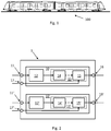
- FIG. 1 shows a rail vehicle according to one embodiment.
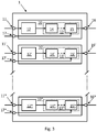
- FIG. 2 shows a schematic control device according to an embodiment.
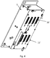
- FIG. 3 shows a schematic control device according to another embodiment.
- FIG. 4 shows a detailed control device according to an embodiment.
- FIG. 1 shows a rail vehicle 100 according to an embodiment.
- Rail vehicles may in particular be trams, metros, electric locomotives or high-speed trains.
- the rail vehicle has a sanding and a rail brake.
- the rail vehicle may have a spring-loaded brake, an emergency release device of the spring-loaded brake or an interior light, which can be controlled by a control device, each with a control module.
- FIG. 2 shows a control device for installation in a rail vehicle and for actuating devices in a rail vehicle
- the control device comprises a housing 1 and at least two control modules 10, 10 'arranged in the housing, and each control module 10, 10' comprises: at least one switching input 11, 11 '; a logic unit 12, 12 'connected to the switching input 11, 11', which can logically process a signal at the switching input 11, 11 '; a semiconductor power switching device 13, 13 'connected to the logic unit 12, 12' and controllable by the logic unit 12, 12 '; at least one power output 16, 16 'connected to the semiconductor power switching device 13, 13', the first control module 10 being connectable via the power output 16 to a first device of a rail vehicle and configured to control and operate the same, the second control module 10 'via the power output 16' with a second Device of a rail vehicle is connectable and adapted to control and operate, and wherein the first device is a sanding and the second device is a rail brake.
- the first control module 10 is provided for sanding and the second control module is provided for a rail brake.
- a control module 10, 10 ' has at least one switching input 11, 11'. Furthermore, each control module 10, 10 'has at least one power output 16, 16'.
- switching inputs 11, 11 'and / or a plurality of power outputs 16, 16' may be provided depending on the device of the rail vehicle. In a concrete exemplary embodiment, this can comprise sanding in each case right and left on two axes. Accordingly, the first control module 10 then has at least four switching inputs 11. Further switching inputs 11 may be provided, for example, for heating the sand nozzle. A different number of switching inputs 11 may result in other embodiments, for example, by a larger number of controllable axes or other functions of the sanding.
- the control module 10 can be adapted accordingly to these requirements.
- the switching inputs 11 can be switched, for example, at a rated voltage of 24 V and a maximum current of 0.7 A.
- the first control module 10 may further comprise one or more power supplies 17, which are each connected to one of the power outputs 16 when switched.
- the first control module 10 has four power outputs 16 for sanding right and left on two axes, as well as four further power outputs for compressors.
- An additional power output 16 may be provided for heating on all four sandings.
- the sandings are operated with a voltage of 24 V and a maximum current of 5 A.
- the compressors can each be operated with 24 V and 25 A and the heating with 24 V and 10 A.
- a control module 10, 10 'for each power output 16, 16' a power supplies 17, 17 ', each power output 16, 16' with an associated power supplies 17, 17 'by switching the semiconductor power switching device 13, 13 ' is electrically connected.
- the nominal voltages at the switching input 11, 11 'and at the line output are limited to a maximum of 24V, for example. This corresponds to the typical rated board network voltage. According to one embodiment, the rated voltage at each switching input 11, 11 'and at each of the power outputs 16, 16' is substantially 24 V.
- the nominal voltage may differ slightly from the actual voltage at the load. For example, a typical voltage at the load is 25 V to 27 V DC.
- the second control module 10 ' may, for example, have two power outputs 16' for connection to the plus potential of a right and a left rail brake. In each case a further output for the negative potential or zero-volt supply potential may also be a part of the control module 10 ', wherein this output does not extend over a controllable semiconductor power switching device 13'. Alternatively, the negative potential may run separately to the control module 10 '.
- the power outputs 16 ' are electrically connected by activation of the rail brake by the logic unit 12 and the semiconductor power switching device 13 to one of the two power supplies 17'. Between the potential of the power supplies 17 'and the zero-volt supply potential (or negative potential) is applied to a rated voltage of 24 volts. The current intensity is limited to 50 A, for example.
- the rail brake comprises a left and a right rail brake magnet.
- an abrasive body is pressed onto the rail and the rail vehicle is braked by mechanical friction.
- the second control module 10 controls this flow of current through the magnets.
- a signal at the switching input 11, 11 ' is processed in the logic unit 12, 12', whereby the controllable semiconductor power switching device 13, 13 'electrically connects the power supplies to the power outputs 16, 16'.
- the logic unit can in particular actuate a gate control 14, 14 'of an IGBT 15, 15'.
- a current can flow via the power output 16, 16 'connected to the IGBT 15.
- the second control module 10 ' the current flows from the power output 16' in the electromagnet of the rail brake.
- the electromagnet presses the grinding wheel onto the rail and it creates a braking effect.
- the control and thus the change of the current through the power outputs 16 ' can be continuously adjustable.
- a control module 10, 10 ' may additionally have one or more signal outputs.
- a signal output may be used on the second control module 10 'to help the vehicle control system track the condition of the rail brake. The status can be described as "ready for operation” at the signal output.
- a second signal output can be used to report to the vehicle control system the activity state of the rail brake, ie "active” and “not active” and thus an actual braking state by a rail brake.
- FIG. 2 shows that the control modules 10, 10 'are electrically independent of each other.
- the control modules 10, 10 ' share neither a switching input 11, 11' nor a power output 16, 16 '.
- the two control modules 10, 10 ' may in particular have separate circuit boards.
- Logic units 12, 12 can each be connected via the gate controls 14, 14 'to the semiconductor power switching devices 13, 13' and control them via the gate controls 14, 14 '. Particularly in the case of a power MOSFET or an IGBT, the semiconductor power switching device 13, 13 'has a gate control 14, 14'.
- FIG. 3 shows a further embodiment of the control device.
- the control device has comparable to FIG. 2 a first and a second control module 10, 10 'for a sanding and a rail brake on. Furthermore, in this embodiment the control device has further control modules 10 *.
- further control modules 10 * may be arranged in the control device for further devices of the rail vehicle in the housing.
- a further, two further or 3 further control modules 10 * can be provided for further devices of the rail vehicle, the device being one of the following: spring-loaded brake, emergency release device of the spring-loaded brake, and interior lighting.
- the control modules 10, 10 ', 10 * have the same basic structure, that is, they each have at least one switching input 11, 11', 11 *, a logic unit 12, 12 'connected to the switching input 11, 11', 11 *, 12 *, which can logically process a signal at the switching input 11, 11 ', 12 *, a semiconductor power switching device 13, 13 connected to the logic unit 12, 12', 12 * and controllable by the logic unit 12, 12 ', 12 * ', 13 *, at least one power output 16, 16', 16 * connected to the semiconductor power switching device 13, 13 ', 13 *.
- Each control module 10, 10 ', 10 * is intended for a device of the rail vehicle and is designed to control and actuate it.
- the control modules 10, 10 ', 10 * are adapted to the respective device can have different numbers of switching inputs 11, 11', 11 *, semiconductor power switching devices 13, 13 ', 13 *, and power outputs 16, 16', 16 *.
- the logic units 12, 12 ', 12 * are adapted to it and to the respective function of the device.
- a control module 10, 10 ', 10 * for one device generally differs from, and is unsuitable for, another control module 10, 10', 10 * for another device.
- FIG. 4 shows a detailed control device according to another embodiment.
- switching input 11, 11 'and power output 16, 16' shown as plug-in connections in the housing 1.
- the housing 1 has, for example, a metal sheet, in particular with an electrical ground, or a plastic.
- the control device may be installed in a rail vehicle 100.
- fastening means may be provided on the housing.
- the plug connections can have a plug coding, so that plug connections of a control module differ mechanically from plug connections of another control module. By a mechanical coding, the control device against the exchange of plugs and thus connecting a control module 10, 10 ', 10 * secured to a wrong device.
- the control device is advantageously compact and has for example a maximum length of 500 mm and a maximum width and depth of 210 mm.
- the maximum weight may be limited to 6 kg.
- the control device bundles a plurality of control modules 10, 10 ', 10 * compact in a housing and offers a space advantage over conventional switching devices, such as relay arrangements, and receives the requirements for a secure operation of the facilities.
Landscapes
- Engineering & Computer Science (AREA)
- Mechanical Engineering (AREA)
- Physics & Mathematics (AREA)
- Electromagnetism (AREA)
- Transportation (AREA)
- Electric Propulsion And Braking For Vehicles (AREA)
- Regulating Braking Force (AREA)
Abstract
Description
- Die Erfindung liegt auf dem Gebiet der Schienenfahrzeug und der elektronischen Betätigung von Einrichtungen und Funktionen in einem Schienenfahrzeug, wie zum Beispiel Bremsen oder Beleuchtung, und betrifft eine Steuerungsvorrichtung zum Einbauen in ein Schienenfahrzeug und zum Betätigen von Einrichtungen in einem Schienenfahrzeug, sowie ein Schienenfahrzeug mit einer Steuerungsvorrichtung.
- Fahrzeugfunktionen wie Bremsen oder Beleuchtungen wurden bisher über konventionellen Schaltgeräte, zum Beispiel Relais, oder über eine zentrale Fahrzeugsteuerung betätigt. Diese Steuervorrichtungen sind meistens über das Schienenfahrzeug an mehreren Orten verteilt.
- Beispielsweise beschreibt
WO 2013/034735 A2 eine Bremssteuereinrichtung für eine Bremsanlage eines Schienenfahrzeugs. - Eine Steuervorrichtung für ein Beleuchtungssystem für Schienenfahrzeuge is dagegen in
EP 2 657 084 A1 beschrieben. - Die verschiedenen Fahrzeugfunktionen können beispielsweise zentral von einem zentralen Fahrerpult, wie beispielsweise in
WO 2015/197479 A1 beschrieben angesteuert werden. - Die Geräteträger konventioneller Schaltungstechnik zur Steuerung verschiedener Fahrzeugeinrichtungen und -funktionen sind platzeinnehmend und über das Schienenfahrzeug verteilt. Außerdem ist deren Ansteuerung aufwendig, da eine verteilte Ansteuerung erforderlich ist.
- Die Aufgabe besteht darin, den Aufbau der Steuervorrichtungen zu verbessern.
- Diese Aufgabe wird durch eine Steuerungsvorrichtung zum Einbauen in ein Schienenfahrzeug nach Anspruch 1 gelöst. Weiterhin wird diese Aufgabe durch ein Schienenfahrzeug mit einer Steuerungsvorrichtung nach Anspruch 15 gelöst.
- Es wird eine Steuerungsvorrichtung zum Einbauen in ein Schienenfahrzeug und zum Betätigen von Einrichtungen in dem Schienenfahrzeug vorgeschlagen. Die Steuerungsvorrichtung weist ein Gehäuse und mindestens zwei in dem Gehäuse angeordnete Steuerungsmodule auf. Jedes Steuerungsmodul weist: mindestens einen Schalteingang; eine mit dem Schalteingang verbundene Logikeinheit, die ein Signal an dem Schalteingang logisch verarbeiten kann; eine mit der Logikeinheit verbundene und durch die Logikeinheit steuerbare Halbleiter-Leistungsschaltvorrichtung; mindestens einen mit der Halbleiter-Leistungsschaltvorrichtung verbundenen Leistungsausgang, wobei das erste Steuerungsmodul über den Leistungsausgang mit einer ersten Einrichtung des Schienenfahrzeuges verbindbar ist und ausgebildet ist, diese zu steuern und zu betätigen, wobei das zweite Steuerungsmodul über den Leistungsausgang mit einer zweiten Einrichtung des Schienenfahrzeuges verbindbar ist und ausgebildet ist, diese zu steuern und zu betätigen, und wobei die erste Einrichtung eine Sandung ist und die zweite Einrichtung eine Schienenbremse ist.
- Schienenfahrzeuge, wie zum Beispiel Straßenbahnen, Metros, elektrische Lokomotiven oder Hochgeschwindigkeitszüge, weisen Einrichtungen für verschiedene Funktionen im Schienenfahrzeug auf. Diese Einrichtungen oder Funktionen können beispielsweise sein: die Schienenbremse, die Sandung, die Federspeicherbremse, die Notauslösevorrichtung der Federspeicherbremse oder die Innenbeleuchtung. Diese Einrichtungen sind elektrisch oder elektromechanisch betätigbar und steuerbar. Die Steuerungsvorrichtung weist mindestens zwei Steuerungsmodule auf, wobei das erste zum Steuern und Betätigen der Sandung ausgebildet ist und das zweite zum Steuern und Betätigen der Schienenbremse ausgebildet ist. Die Steuerungsvorrichtung kann weitere Steuerungsmodule zum Steuern und Betätigen weiterer Einrichtungen aufweisen.
- Gemäß einer Ausführungsform weist die Steuerungsvorrichtung mindestens ein drittes in dem Gehäuse angeordnetes Steuerungsmodul auf. Das dritte Steuerungsmodul ist über seinen Leistungsausgang mit einer dritten Einrichtung eines Schienenfahrzeuges verbindbar und ausgebildet, diese zu steuern und zu betätigen. Die dritte Einrichtung ist eine der folgenden: die Federspeicherbremse, die Notauslösevorrichtung der Federspeicherbremse oder die Innenbeleuchtung.
- Gemäß einer Ausführungsform kann die Steuerungsvorrichtung ein viertes in dem Gehäuse angeordnetes Steuerungsmodul aufweisen. Das vierte Steuerungsmodul ist über seinen Leistungsausgang mit einer vierten Einrichtung eines Schienenfahrzeuges verbindbar und ausgebildet, diese zu steuern und zu betätigen. Die vierte Einrichtung ist eine der folgenden: die Federspeicherbremse, die Notauslösevorrichtung der Federspeicherbremse oder die Innenbeleuchtung, wobei die dritte Steuerungsvorrichtung und die vierte Steuerungsvorrichtung für unterschiedliche Einrichtungen vorgesehen sind.
- Über das Steuerungsmodul kann die jeweilige Einrichtung angesteuert werden. Ein Steuern und Betätigen kann ein Schalten zwischen zwei Zuständen, beispielsweise bei der Innenbeleuchtung ein Schalten zwischen Ein und Aus einer Stromversorgung einer Beleuchtungseinrichtung, beinhalten. Ein Steuern und Betätigen kann insbesondere auch ein stetiges und/oder stufenloses Betätigen beispielsweise einer Schienenbremse beinhalten. Das Steuern und Betätigen kann insbesondere die Steuerung des Stromflusses über den Leistungsausgang umfassen.
- Die Steuerungsmodule sind in einem Gehäuse angeordnet. Beispielsweise sind die in dem Gehäuse mechanisch befestigt. Weiterhin können die Schalteingänge und die Leistungsausgänge der Steuerungsmodule aus dem Gehäuse geführt werden, beispielsweise durch Steckverbindungen. Weiterhin kann eine Stromversorgung in das Gehäuse zu den Steuerungsmodulen geführt werden.
- Gemäß einer Ausführungsform weist ein Steuerungsmodul eine Spannungsversorgung (oder auch Stromversorgung) auf, wobei ein Steuern der Halbleiter-Leistungsschaltvorrichtung eine elektrische Verbindung zwischen der Spannungsversorgung und dem Leistungsausgang steuert. Ein Steuerungsmodul kann ebenso mehrere Spannungsversorgungen aufweisen. Die Anzahl der Spannungsversorgungen hängt von der Anzahl der Leistungsausgänge ab. Verschiedene Steuerungsmodule können eine Unterschiedliche Anzahl von Spannungsversorgungen aufweisen.
- Das Gehäuse ist in ein Schienenfahrzeug einbaubar. Es ist kompakt und kann beispielsweise Im Randbereich eines Innenraumes eines Wagenkastens eingebaut werden, ohne die den Platz für Fahrgäste wesentlich zu beschränken.
- Jedes Steuerungsmodul weist einen Schalteingang auf. Insbesondere kann jedes Steuerungsmodul mehrere Schalteingänge, beispielsweise 1, 2, 4, oder 8, aufweisen. Die Anzahl der Schalteingänge kann sich bei unterschiedlichen Steuerungsmodulen je nach Anforderung der zu steuernden Einrichtung unterscheiden.
- Jedes Steuerungsmodul weist einen Leistungsausgang auf. Insbesondere kann jedes Steuerungsmodul mehrere Leistungsausgänge, beispielsweise 1, 2, 3, 5 oder 9, aufweisen. Die Anzahl der Leistungsausgänge kann sich bei unterschiedlichen Steuerungsmodulen je nach Anforderung der zu steuernden Einrichtung unterscheiden. Die Schienenbremse kann beispielsweise mit zwei Leistungsausgängen angesteuert werden, während die Innenbeleuchtung beispielsweise durch sechs Leistungsausgänge angesteuert werden kann.
- An dem Schalteingang kann ein Signal anliegen. Insbesondere kann ein binäres Signal, also ein Signal aus zwei Zuständen, Ein und Aus oder Null und Eins, an dem Schalteingang anliegen. Die Zustände können durch eine Spannungs-, oder Leistungsschwelle am Signaleingang definiert sein.
- Mit dem Schalteingang ist eine Logikeinheit verbunden, die das Signal an dem Schalteingang logisch verarbeiten kann. Mit der Logikeinheit ist eine steuerbare Halbleiter Leistungsschaltvorrichtung verbunden und durch die Logikeinheit steuerbar. Die Halbleiter Leistungsschaltvorrichtung ist mit dem Leistungsausgang verbunden. Durch diese Verbindungen beeinflusst ein Signal an dem oder an den Schalteingängen den Stromfluss über den Leistungsausgang. Gemäß einer Ausführungsform ist jedem zulässigen Signal am Schalteingang eines Steuerungsmoduls ein definierter Stromfluss an dem oder an den Leistungsausgängen zugewiesen. Das Verhalten eines Steuerungsmodules kann dadurch durch eine Logiktabelle, die die Spannung beziehungsweise den Strom am Leistungsausgang in Abhängigkeit von dem Eingangssignal am Schalteingang darstellt, beschrieben werden.
- Jedes Steuerungsmodul kann weiterhin Eingänge für die Spannungsversorgung aufweisen. Gemäß einem Ausführungsbeispiel werden beim Steuern die Spannungsversorgung und der Leistungsausgang elektrisch leitend verbunden. Die elektrische Verbindung führt über die Halbleiter-Leistungsschaltvorrichtung und wird durch die Logikeinheit und das Signal am Schalteingang gesteuert.
- Ein Steuerungsmodul kann ein oder mehrere Eingänge für die Spannungsversorgung aufweisen. Die Anzahl der Spannungsversorgungen hängt von der Anzahl der Leistungsausgänge und der anzuschließenden Einrichtung ab. Die Spannungsversorgungen von zwei Steuerungsmodulen können insbesondere elektrisch unabhängig sein, sodass eine Fehlfunktion an einer Spannungsversorgung in einem Steuerungsmodul nicht auf ein anderes Steuerungsmodul übertragen werden kann.
- Ein Steuerungsmodul kann weiterhin ein oder mehrere nicht steuerbare Spannungsein- und -ausgänge aufweisen. Dieser oder diese können das entgegengesetzte Potential zum Leistungsausgang zu Verfügung stellen, damit ein Strom vom Leistungsausgang zur Einrichtung fließen kann.
- Gemäß einer Ausführungsform ist der Leistungsausgang eines Steuerungsmoduls unabhängig von den Schalteingängen anderer Steuerungsmodule, das heißt, ein Signale an einem Schalteingang an einem erstem Steuerungsmodul kann den Stromfluss durch den Leistungsausgang an einem anderen Steuerungsmodul nicht beeinflussen. Der Verarbeitungsweg des Signals in der Logikeinheit eines Steuerungsmodules ist von anderen Logikeinheiten anderer Steuerungsmodule elektrisch getrennt.
- Gemäß einer Ausführungsform kann ein Steuerungsmodul einen Signalausgang aufweisen. Dieser gibt beispielsweise eine Rückmeldung über einen Zustand der Logikeinheit, wie "Ein" und "Aus" oder "aktiv" und "nicht aktiv" an. Beispielweise kann es vorteilhaft sein, einen Signalausgang für die Innenbeleuchtung vorzusehen, der signalisiert, ob die Innenbeleuchtung aktiviert ist oder nicht.
- Gemäß einer Ausführungsform entspricht die Signalverarbeitung in jedem Steuerungsmodul vom dem Schalteingang zu dem Leistungsausgang dem Standard nach EN 50129:2003. Darin werden unter anderem möglichen Topologien zum sicheren Betreiben dargestellt. Beispielsweise kann bei der Signalverarbeitung durch Redundanz oder eine Überwachungsfunktion des Signalweges die Sicherheit nachgewiesen werden.
- Gemäß einer Ausführungsform ist in jedes Steuerungsmodul eine Überwachungsfunktion integriert, die die Plausibilität des Signales an dem jeweiligen Schalteingang und des dazugehörigen Zustandes des Leistungsausganges überwacht.
- Gemäß einer Ausführungsform weißt die Logikeinheit Verknüpfungen aus "UND"- sowie "ODER"-Verbindungen auf. Diese können in diskreten Bauteilen zusammengesetzt und beispielsweise auf eine Platine gelötet werden. Die Logigeinheit kann ebenso integrierte Schaltkreise aufweisen, beispielsweise Field Programmable Gate Array (FPGA) oder einen Microcontroller.
- Gemäß einer Ausführungsform ist die Logikeinheit aus fest verdrahteten Logikgattern aufgebaut. Die Logikgatter sind beispielsweise auf eine Platine aufgelötet. Durch eine Hardware-basierte Logik wird im Vergleich zu einer Software-basierten Logik die Fehleranfälligkeit verringert. Dadurch werden Sicherheitsstandards für die Ansteuerung der Einrichtungen im Schienenfahrzeug erfüllt. Entsprechend der Gatter wird ein Eingangssignal am Schalteingang verarbeitet und der Stromfluss durch den Leistungsausgang gesteuert.
- Gemäß einer Ausführungsform weisen die Steuerungsmodule jeweils separate Platinen auf, auf denen die Logikeinheiten aufgebracht sind. Das ermöglicht vorteilhaft die Austauschbarkeit von Steuerungsmodulen. Des Weiteren sind die Steuerungsmodule dadurch elektrisch unabhängig voneinander, wodurch beispielsweise ein elektrischer Defekt oder ein fehlerhaftes Signal in einem Steuerungsmodul nicht auf ein anderes Steuerungsmodul übertragen wird.
- Die Halbleiter-Leistungsschaltvorrichtung kann beispielsweise einen Leistungs-MOSFET oder einen IGBT aufweisen. Unterschiedliche Steuerungsmodule können gleich oder unterschiedlich ausgestaltet sein, sodass die Halbleiter-Leistungsschaltvorrichtung eines Steuerungsmodules beispielsweise einen Leistungs-MOSFET aufweist und die Halbleiter-Leistungsschaltvorrichtung eines anderen Steuerungsmodules beispielsweise einen IGBT aufweist.
- Die Halbleiter-Leistungsschaltvorrichtung kann eine Gatesteuerung aufweisen und die Logikeinheiten können jeweils über die Gatesteuerungen mit der Halbleiter-Leistungsschaltvorrichtungen verbunden sein und diese über die Gatesteuerungen steuern. Insbesondere bei einem Leistungs-MOSFET oder einen IGBT weist die Halbleiter-Leistungsschaltvorrichtung eine Gatesteuerung auf.
- Gemäß einer Ausführungsform weist die Steuerungsvorrichtung eine Kühlvorrichtung zum Kühlen des Innenbereiches des Gehäuses, insbesondere zum Kühlen einer der oder mehrerer steuerbaren Halbleiter-Leistungsschaltvorrichtungen auf. Die Kühlvorrichtung kann eine passive Kühlung, beispielsweise Kühlrippen und/oder eine aktive Kühlung beispielsweise eine Wasserkühlung umfassen. Im Gehäuse entsteht im Betriebszustand Wärme. Insbesondere entsteht Wärme in den Halbleiter-Leistungsschaltvorrichtung, da dort höhere Ströme fließen können als an den Steuerungseingängen. Eine Kühlvorrichtung schützt die Halbleiter-Leistungsschaltvorrichtungen vor Zerstörung durch Hitze.
- Gemäß einer Ausführungsform weist das Gehäuse Verbindungselemente nach außen zum elektrischen Verbinden mit einer Einrichtung in einem Schienenfahrzeug auf, an die Leistungsausgänge angeschlossen sind. Die Schalteingänge der Steuerungsmodule und die Spannungsversorgungen können jeweils auch mit Verbindungselement im Innenraum des Gehäuses nach Außen anschließbar sein. Die Schalteingänge und die Leistungsausgänge eines Steuerungsmoduls werden dadurch unabhängig von anderen Steuerungsmodulen aus dem Gehäuse nach Außen geführt. Die Verbindungselemente können Steckverbindungen sein und vorteilhaft eine Steckercodierung aufweisen, sodass der Stecker jeder Einrichtung im Schienenfahrzeug ein-eindeutig jeder Steckverbindung und damit jedem Steuerungsmodul zugeordnet ist. Ein falsches Anschließen einer Einrichtung des Schienenfahrzeuges an einen Leistungsausgang eines Steuerungsmoduls ist dadurch ausgeschlossen. Ebenso ist ein falsches Anschließen an einen Schalteingang beispielsweise einer Fahrzeugleittechnik oder eines Bedienterminals (Hardwareschaltung) durch eine Steckercodierung ausgeschlossen.
- Gemäß einer Ausführungsform ist die Steuerungsvorrichtung mit der Fahrzeugleittechnik eines Schienenfahrzeuges verbindbar und einerseits über diese steuerbar, wobei die Steuerungsvorrichtung weiterhin eine Hardwareschaltung aufweist und andererseits über die Hardwareschaltung steuerbar ist. Die Steuerungsvorrichtung kann über Befehle aus der Fahrzeugleittechnik in der Führerkabine des Schienenfahrzeuges steuerbar sein. Zusätzlich kann die Steuerungsvorrichtung über eine Hardwareschaltung, beispielsweise ein Bedienpanel oder Taster, steuerbar sein.
- Gemäß einer Ausführungsform beträgt die Nennspannung an den Leistungsausgängen 24 V. Diese 24 V entsprechen typischerweise der Bordnetzspannung von Schienenfahrzeugen und damit dem vom Hersteller oder Lieferanten spezifizierten Wert der elektrischen Spannung im Normalbetrieb der Einrichtung im Schienenfahrzeug. Die Nennspannung beschreibt den Normalbetrieb, wobei es während des Betriebes zu Spannungsschwankungen kommen kann. Beispielsweise beträgt die Mindestspannung 16,8 V und die Höchstspannung 30,0 V. Gemäß einer Ausführungsform beträgt die Nennspannung an den Schalteingängen ebenso 24 V.
- Die Schalteingänge können sich von den Leitungseingängen durch einen höheren Stromfluss unterscheiden. Bei gleicher Spannung resultiert daraus eine höhere Leistung. Die maximale Stromstärke bei einem mit 24 V Spannung versorgtem Schalteingang beträgt beispielsweise 0,7 A oder 0,85 A. Im Vergleich dazu kann die maximale Stromstärke an einem Leistungsausgang oder an einer Spannungsversorgung bei ebenso 24 V bei beispielsweise 1 A, 20 A oder 50 A liegen. Die benötigte Stromstärke und damit Leistung hängt von der Einrichtung ab. Während beispielsweise für das Ansteuern einer Federspeicherbremse wenig Leistung benötigt wird, wird beim Ansteuern einer Schienenbremse eine hohe Leistung benötigt.
- Es wird weiterhin ein Schienenfahrzeug vorgeschlagen, wobei das Schienenfahrzeug Einrichtung und eine Ausführungsform der Steuerungsvorrichtung aufweist, wobei jeweils das Steuerungsmodul (10, 10') über den Leistungsausgang (16, 16') mit einer Einrichtung verbunden ist und diese steuern und betätigen kann. Die Einrichtungen sind dabei die Schienenbremse und die Sandung des Schienenfahrzeuges, sowie weiterhin beispielsweise die Federspeicherbremse, die Notauslösevorrichtung der Federspeicherbremse oder die Innenbeleuchtung des Schienenfahrzeuges.
- Die beiliegenden Zeichnungen veranschaulichen Ausführungsformen und dienen zusammen mit der Beschreibung der Erläuterung der Prinzipien der Erfindung. Die Elemente der Zeichnungen sind relativ zueinander und nicht notwendigerweise maßstabsgetreu. Gleiche Bezugszeichen bezeichnen ähnliche Teile.
-
Figur 1 zeigt ein Schienenfahrzeug gemäß einer Ausführungsform. -
Figur 2 zeigt eine schematische Steuerungsvorrichtung gemäß einer Ausführungsform. -
Figur 3 zeigt eine schematische Steuerungsvorrichtung gemäß einer weiteren Ausführungsform. -
Figur 4 zeigt eine detaillierte Steuerungsvorrichtung gemäß einer Ausführungsform. -
Figur 1 zeigt ein Schienenfahrzeug 100 gemäß einer Ausführungsform. Schienenfahrzeuge können insbesondere Straßenbahnen, Metros, elektrische Lokomotiven oder Hochgeschwindigkeitszüge sein. Das Schienenfahrzeug weist eine Sandung und eine Schienenbremse auf. Weiterhin kann das Schienenfahrzeug eine Federspeicherbremse, eine Notauslösevorrichtung der Federspeicherbremse oder eine Innenbeleuchtung aufweisen, die durch eine Steuerungsvorrichtung mit jeweils einem Steuerungsmodul gesteuert werden können. -
Figur 2 zeigt eine Steuerungsvorrichtung zum Einbauen in ein Schienenfahrzeug und zum Betätigen von Einrichtungen in einem Schienenfahrzeug, wobei die Steuerungsvorrichtung ein Gehäuse 1 und mindestens zwei in dem Gehäuse angeordnete Steuerungsmodule 10, 10' aufweist und jedes Steuerungsmodul 10, 10' aufweist: mindestens einen Schalteingang 11, 11'; eine mit dem Schalteingang 11, 11' verbundene Logikeinheit 12, 12', die ein Signal an dem Schalteingang 11, 11' logisch verarbeiten kann; eine mit der Logikeinheit 12, 12' verbundene und durch die Logikeinheit 12, 12' steuerbare Halbleiter-Leistungsschaltvorrichtung 13, 13'; mindestens einen mit der Halbleiter-Leistungsschaltvorrichtung 13, 13' verbundenen Leistungsausgang 16, 16', wobei das erste Steuerungsmodul 10 über den Leistungsausgang 16 mit einer ersten Einrichtung eines Schienenfahrzeuges verbindbar ist und ausgebildet ist, diese zu steuern und zu betätigen, wobei das zweite Steuerungsmodul 10' über den Leistungsausgang 16' mit einer zweiten Einrichtung eines Schienenfahrzeuges verbindbar ist und ausgebildet ist, diese zu steuern und zu betätigen, und wobei die erste Einrichtung eine Sandung ist und die zweite Einrichtung eine Schienenbremse ist. - Das erste Steuerungsmodul 10 ist für eine Sandung vorgesehen und das zweite Steuerungsmodul ist für eine Schienenbremse vorgesehen.
- Ein Steuerungsmodul 10, 10' weist mindestens einen Schalteingang 11, 11' auf. Weiterhin weist jedes Steuerungsmodul 10, 10' mindestens einen Leistungsausgang 16, 16' auf. Mehrere Schalteingänge 11, 11' und/oder mehrere Leistungsausgänge 16, 16' können je nach Einrichtung des Schienenfahrzeuges vorgesehen sein. Dies kann in einem konkreten Ausführungsbeispiel die Sandung jeweils Rechts und Links an zwei Achsen umfassen. Dementsprechend weist das erste Steuerungsmodul 10 dann mindestens vier Schalteingänge 11 auf. Weitere Schalteingänge 11 können beispielsweise für eine Heizung der Sanddüse vorgesehen sein. Eine andere Anzahl von Schalteingängen 11 kann in anderen Ausführungsformen beispielsweise durch eine größere Anzahl von steuerbaren Achsen oder weiteren Funktionen der Sandung entstehen. Das Steuerungsmodul 10 kann entsprechend an diese Anforderungen angepasst werden. Die Schalteingänge 11 können beispielsweise bei einer Nennspannung von 24 V und einer Stromstärke von maximal 0,7 A geschaltet werden.
- Das erste Steuerungsmodul 10 kann weiterhin ein oder mehrere Spannungsversorgungen 17 aufweisen, die bei einem Schalten jeweils mit einem der Leistungsausgänge 16 verbunden werden. Beispielsweise weist das erste Steuerungsmodul 10 vier Leistungsausgänge 16 für die Sandung Rechts und Links an zwei Achsen, sowie vier weitere Leistungsausgänge für Kompressoren auf. Ein zusätzlicher Leistungsausgang 16 kann für die Heizung an allen vier Sandungen vorgesehen sein. Beispielsweise werden die Sandungen mit einer Spannung von 24 V und einer maximalen Stromstärke von 5 A betrieben. Die Kompressoren können jeweils mit 24 V und 25A betrieben werden und die Heizung mit 24 V und 10 A.
- Gemäß einer Ausführungsform weist ein Steuerungsmodul 10, 10' für jeden Leistungsausgang 16, 16' eine Spannungsversorgungen 17, 17' auf, wobei jeder Leistungsausgang 16, 16' mit einer zugeordnetem Spannungsversorgungen 17, 17' durch ein Schalten der Halbleiter-Leistungsschaltvorrichtung 13, 13' elektrisch verbunden wird.
- Die Nennspannungen am Schalteingang 11, 11' und am Leitungsausgang sind beispielsweise auf maximal 24V begrenzt. Dies entspricht der typischen Boardnetz-Nennspannung. Gemäß einer Ausführungsform beträgt die Nennspannung an jedem Schalteingang 11,11' und an jedem der Leistungsausgänge 16, 16' im Wesentlichen 24 V. Die Nennspannung kann dabei gering von der tatsächlichen Spannung am Verbraucher abweichen. Beispielsweise beträgt eine typische Spannung am Verbraucher 25 V bis 27 V Gleichspannung.
- Das zweite Steuerungsmodul 10' kann beispielsweise zwei Leistungsausgänge 16' zum Verbinden mit dem Plus-Potential einer rechten und einer linken Schienenbremse aufweisen. Jeweils ein weiterer Ausgang für das Minus-Potential oder Null-Volt-Versorgungspotential kann ebenso ein Teil des Steuerungsmodules 10' sein, wobei dieser Ausgang nicht über eine steuerbare Halbleiter Leistungsschaltvorrichtung 13' verläuft. Alternativ kann das Minus-Potential separat zum Steuerungsmodul 10' verlaufen. Die Leistungsausgänge 16' werden bei einem Aktivieren der Schienenbremse elektrisch durch die Logikeinheit 12 und die Halbleiter-Leistungsschaltvorrichtung 13 mit jeweils einem der zwei Spannungsversorgungen 17' verbunden. Zwischen dem Potential der Spannungsversorgungen 17' und dem Null-Volt-Versorgungspotential (oder Minus-Potential) liegt eine Nennspannung von 24 V an. Die Stromstärke ist beispielsweise auf 50 A begrenzt.
- In einer Gestaltungsmöglichkeit einer Schienenbremse entwickelt diese eine Bremswirkung durch einen Stromfluss durch Schienenbremsenmagnete. Die Schienenbremse umfasst einen linken und einen rechten Schienenbremsenmagneten. Bei einem Stromdurchfluss durch den Magneten wird ein Schleifkörper auf die Schiene gedrückt und das Schienenfahrzeug durch mechanische Reibung gebremst. Das zweite Steuerungsmodul 10' steuert diesen Stromfluss durch die Magneten.
- Ein Signal am Schalteingang 11, 11' wird in der Logikeinheit 12, 12' verarbeitet, wodurch die steuerbare Halbleiter Leistungsschaltvorrichtung 13, 13' die Spannungsversorgungen mit den Leistungsausgängen 16, 16' elektrisch verbindet. Die Logikeinheit kann dazu insbesondere eine Gatesteuerung 14, 14' eines IGBTs 15, 15' betätigen. Dadurch kann ein Strom über den mit dem IGBT 15 verbundenen Leistungsausgang 16, 16' fließen. Bei dem zweiten Steuerungsmodul 10' fließt der Strom aus dem Leistungsausgang 16' in den Elektromagneten der Schienenbremse. Dadurch presst der Elektromagnet durch das entstehende Magnetfeld den Schleifkörper auf die Schiene und es entsteht eine Bremswirkung. Die Steuerung und damit die Veränderung der Stromstärke durch die Leistungsausgänge 16' kann kontinuierlich einstellbar sein.
- Ein Steuerungsmodul 10, 10' kann zusätzlich ein oder mehrere Signalausgänge aufweisen. Ein Signalausgang kann beispielsweise beim zweiten Steuerungsmodul 10' verwendet werden, um der Fahrzeugleittechnik den Zustand der Schienenbremse mitzueilen. Der Zustand kann bei dem Signalausgang als "betriebsbereit" beschrieben werden. Ein zweiter Signalausgang kann verwendet werden, um der Fahrzeugleittechnik den Aktivitätszustand der Schienenbremse, also "aktiv" und "nicht aktiv" und damit einen tatsächlichen Bremszustand durch eine Schienenbremse, zu melden.
- Die
Figur 2 zeigt, dass die Steuerungsmodule 10, 10' elektrisch voneinander unabhängig sind. Die Steuerungsmodule 10, 10' teilen sich weder einen Schalteingang 11, 11' noch einen Leistungsausgang 16, 16'. Die beiden Steuerungsmodule 10, 10' können insbesondere separate Platinen aufweisen. - Ein Schalteingang 11, 11' kann insbesondere mit einer Gatesteuerung 14, 14' einer Halbleiter-Leistungsschaltvorrichtung 13, 13' verbunden sein und dadurch die Leistungsausgänge 16, 16' schalten.
- Logikeinheiten 12, 12 können jeweils über die Gatesteuerungen 14, 14' mit der Halbleiter-Leistungsschaltvorrichtungen 13, 13' verbunden sein und diese über die Gatesteuerungen 14, 14' steuern. Insbesondere bei einem Leistungs-MOSFET oder einen IGBT weist die Halbleiter-Leistungsschaltvorrichtung 13, 13' eine Gatesteuerung 14, 14' auf.
- Die
Figur 3 zeigt eine weitere Ausführungsform der Steuerungsvorrichtung. Die Steuerungsvorrichtung weist vergleichbar zurFigur 2 ein erstes und ein zweites Steuerungsmodul 10, 10' für eine Sandung und eine Schienenbremse auf. Weiterhin weist die Steuerungsvorrichtung in dieser Ausführungsform weitere Steuerungsmodule 10* auf. - Wie in
Figur 3 angedeutet können mehrere weitere Steuerungsmodule 10* in der Steuerungsvorrichtung für weitere Einrichtungen des Schienenfahrzeuges im Gehäuse angeordnet sein. Insbesondere können ein weiteres, zwei weitere oder 3 weitere Steuerungsmodule 10* für weitere Einrichtungen des Schienenfahrzeuges vorgesehen sein, wobei die Einrichtung eine der folgenden ist: Federspeicherbremse, Notauslösevorrichtung der Federspeicherbremse, und Innenbeleuchtung. - Die Steuerungsmodule 10, 10', 10* haben den gleichen Grundaufbau, das heißt, sie haben alle jeweils mindestens einen Schalteingang 11, 11', 11*, eine mit dem Schalteingang 11, 11', 11* verbundene Logikeinheit 12, 12', 12*, die ein Signal an dem Schalteingang 11, 11', 12* logisch verarbeiten kann, eine mit der Logikeinheit 12, 12', 12* verbundene und durch die Logikeinheit 12, 12', 12* steuerbare Halbleiter-Leistungsschaltvorrichtung 13, 13', 13*, mindestens einen mit der Halbleiter-Leistungsschaltvorrichtung 13, 13', 13* verbundenen Leistungsausgang 16, 16', 16*. Jedes Steuerungsmodule 10, 10', 10* ist für eine Einrichtung des Schienenfahrzeuges vorgesehen und ausgebildet, diese zu steuern und zu betätigen. Die Steuerungsmodule 10, 10', 10* sind an die jeweilige Einrichtung angepasst können unterschiedliche Anzahlen von Schalteingängen 11, 11', 11*, Halbleiter-Leistungsschaltvorrichtungen 13, 13', 13*, und Leistungsausgängen 16, 16', 16* aufweisen. Die Logikeinheiten 12, 12', 12* sind darauf und auf die jeweilige Funktion der Einrichtung angepasst. Ein Steuerungsmodul 10, 10', 10* für eine Einrichtung unterscheidet sich im Allgemeinen von einem anderen Steuerungsmodul 10, 10', 10* für eine andere Einrichtung und ist für diese ungeeignet.
-
Figur 4 zeigt eine detaillierte Steuerungsvorrichtung gemäß einer weiteren Ausführungsform. Es sind Schalteingang 11, 11' und Leistungsausgang 16, 16' als Steckverbindungen im Gehäuse 1 dargestellt. Das Gehäuse 1 weist beispielsweise ein Blech, insbesondere mit einer elektrischen Erdung, oder einen Kunststoff auf. Die Steuerungsvorrichtung kann in ein Schienenfahrzeug 100 eingebaut werden. Dazu können Befestigungsmittel an dem Gehäuse vorgesehen sein. - Zum Anschließen der Einrichtungen im Schienenfahrzeug an die Steuerungsvorrichtung können Klemmen und/oder Steckverbindungen verwendet werden. Beispielsweise werden zehn Klemmen zu einem Steckverbindungsblock zusammengefasst. Die Steckverbindungen können eine Steckercodierung aufweisen, sodass sich Steckverbindungen eines Steuermodules von Steckverbindungen eines anderen Steuermodules mechanisch unterscheiden. Durch eine mechanische Codierung ist die Steuerungsvorrichtung gegen das Vertauschen von Steckern und damit ein Verbinden eines Steuerungsmodules 10, 10', 10* an eine falsche Einrichtung abgesichert.
- Die Steuerungsvorrichtung ist vorteilhaft kompakt und hat beispielsweise eine maximale Länge von 500 mm und eine maximale Breite und Tiefe von 210 mm. Das Maximalgewicht kann auf 6 kg beschränkt sein. Die Steuerungsvorrichtung bündelt mehreren Steuerungsmodule 10, 10', 10* kompakt in einem Gehäuse und bietet einen Platzvorteil gegenüber konventionellen Schaltgeräten, zum Beispiel Relaisanordnungen, und erhält die Anforderungen an ein abgesichertes Betreiben der Einrichtungen.
Claims (15)
- Steuerungsvorrichtung zum Einbauen in ein Schienenfahrzeug und zum Betätigen von Einrichtungen in dem Schienenfahrzeug, wobei die Steuerungsvorrichtung ein Gehäuse (1) und mindestens zwei in dem Gehäuse angeordnete Steuerungsmodule (10, 10') aufweist und jedes Steuerungsmodul (10, 10') aufweist:- mindestens einen Schalteingang (11, 11');- eine mit dem Schalteingang (11, 11') verbundene Logikeinheit (12, 12'), die ein Signal an dem Schalteingang (11, 11') logisch verarbeiten kann;- eine mit der Logikeinheit (12, 12') verbundene und durch die Logikeinheit (12, 12') steuerbare Halbleiter-Leistungsschaltvorrichtung (13, 13');- mindestens einen mit der Halbleiter-Leistungsschaltvorrichtung (13, 13') verbundenen Leistungsausgang (16, 16'),wobei das erste Steuerungsmodul (10) über den Leistungsausgang (16) mit einer ersten Einrichtung des Schienenfahrzeuges verbindbar ist und ausgebildet ist, diese zu steuern und zu betätigen,
wobei das zweite Steuerungsmodul (10') über den Leistungsausgang (16') mit einer zweiten Einrichtung des Schienenfahrzeuges verbindbar ist und ausgebildet ist, diese zu steuern und zu betätigen, und
wobei die erste Einrichtung eine Sandung ist und die zweite Einrichtung eine Schienenbremse ist. - Steuerungsvorrichtung nach Anspruch 1, wobei die Steuerungsmodule (10, 10') jeweils separate Platinen aufweisen, auf denen die Logikeinheiten (12, 12') aufgebracht ist.
- Steuerungsvorrichtung nach einem der vorherigen Ansprüche, weiterhin aufweisend mindestens ein drittes in dem Gehäuse (1) angeordnetes Steuerungsmodul (10"), wobei das dritte Steuerungsmodul (10") über seinen Leistungsausgang (16") mit einer dritten Einrichtung des Schienenfahrzeuges verbindbar ist und ausgebildet ist, diese zu steuern und zu betätigen, wobei die dritte Einrichtung eine der folgenden ist: Federspeicherbremse, Notauslösevorrichtung der Federspeicherbremse, und Innenbeleuchtung.
- Steuerungsvorrichtung nach Anspruch 3, weiterhin aufweisend ein viertes in dem Gehäuse (1) angeordnetes Steuerungsmodul (10""), wobei das vierte Steuerungsmodul über seinen Leistungsausgang (10"") mit einer weiteren der genannten Vorrichtungen verbindbar ist und ausgebildet ist, diese zu steuern und zu betätigen.
- Steuerungsvorrichtung nach einem der vorherigen Ansprüche, wobei das Gehäuse (1) Verbindungselemente nach außen zum elektrischen Verbinden mit einer Einrichtung in einem Schienenfahrzeug aufweist und die Schalteingänge (11, 11') der Steuerungsmodule (10, 10') jeweils an ein eigenes Verbindungselement im Innenraum des Gehäuses (1) angeschlossen sind.
- Steuerungsvorrichtung nach Anspruch 5, wobei die Verbindungselemente Steckverbindungen sind und die Steckverbindungen eine Steckercodierung aufweisen.
- Steuerungsvorrichtung nach einem der vorherigen Ansprüche, wobei jede Halbleiter-Leistungsschaltvorrichtung (13, 13') einen Leistungs-MOSFET (15, 15') oder einen IGBT (15, 15') aufweist.
- Steuerungsvorrichtung nach einem der vorherigen Ansprüche, wobei jede Halbleiter-Leistungsschaltvorrichtung (13, 13') eine Gatesteuerung (14, 14') aufweist und die Logikeinheiten (12, 12') jeweils über die Gatesteuerungen (14, 14') mit der Halbleiter-Leistungsschaltvorrichtungen (13, 13') verbunden sind und diese über die Gatesteuerungen (14, 14') steuern.
- Steuerungsvorrichtung nach einem der vorherigen Ansprüche, wobei in jedes Steuerungsmodul (10, 10') eine Überwachungsfunktion integriert ist, die die Plausibilität des Signales an dem jeweiligen Schalteingang (11, 11') und des dazugehörigen Zustandes des Leistungsausganges (16, 16') überwacht.
- Steuerungsvorrichtung nach einem der vorherigen Ansprüche, weiterhin aufweisend:- eine Kühlvorrichtung zum Kühlen des Innenbereiches des Gehäuses (1), insbesondere zum Kühlen einer der steuerbaren Halbleiter-Leistungsschaltvorrichtung (13, 13').
- Steuerungsvorrichtung nach einem der vorherigen Ansprüche, wobei die Logikeinheiten (12, 12') aus fest verdrahteten Logikgattern aufgebaut ist.
- Steuerungsvorrichtung nach einem der vorherigen Ansprüche, wobei die Steuerungsvorrichtung mit der Fahrzeugleittechnik eines Schienenfahrzeuges verbindbar und einerseits über diese steuerbar ist und wobei die Steuerungsvorrichtung weiterhin eine Hardwareschaltung aufweist und andererseits über die Hardwareschaltung steuerbar ist.
- Steuerungsvorrichtung nach einem der vorherigen Ansprüche, wobei die Signalverarbeitung in jedem Steuerungsmodul (10, 10') vom dem Schalteingang (11, 11') zu dem Leistungsausgang (16, 16') dem Standard nach EN 50129:2003 entspricht.
- Steuerungsvorrichtung nach einem der vorherigen Ansprüche, wobei die Nennspannung an den Leistungsausgängen (16, 16') bei 24 V liegt.
- Schienenfahrzeug mit Einrichtungen und einer Steuerungsvorrichtung nach einem der vorherigen Ansprüche, wobei jeweils das Steuerungsmodul (10, 10') über den Leistungsausgang (16, 16') mit einer Einrichtung verbunden ist und diese steuern und betätigen kann.
Priority Applications (1)
| Application Number | Priority Date | Filing Date | Title |
|---|---|---|---|
| PL18196545T PL3461717T3 (pl) | 2017-09-29 | 2018-09-25 | Urządzenie sterujące do zamontowania w pojeździe szynowym i do uruchamiania urządzeń w pojeździe szynowym oraz pojazd szynowy z urządzeniem sterującym |
Applications Claiming Priority (1)
| Application Number | Priority Date | Filing Date | Title |
|---|---|---|---|
| DE102017122762.8A DE102017122762A1 (de) | 2017-09-29 | 2017-09-29 | Steuerungsvorrichtung zum Einbauen in ein Schienenfahrzeug und zum Betätigen von Einrichtungen in einem Schienenfahrzeug, sowie ein Schienenfahrzeug mit einer Steuerungsvorrichtung |
Publications (3)
| Publication Number | Publication Date |
|---|---|
| EP3461717A2 true EP3461717A2 (de) | 2019-04-03 |
| EP3461717A3 EP3461717A3 (de) | 2019-04-24 |
| EP3461717B1 EP3461717B1 (de) | 2021-09-08 |
Family
ID=63683742
Family Applications (1)
| Application Number | Title | Priority Date | Filing Date |
|---|---|---|---|
| EP18196545.0A Active EP3461717B1 (de) | 2017-09-29 | 2018-09-25 | Steuerungsvorrichtung zum einbauen in ein schienenfahrzeug und zum betätigen von einrichtungen in einem schienenfahrzeug, sowie ein schienenfahrzeug mit einer steuerungsvorrichtung |
Country Status (5)
| Country | Link |
|---|---|
| EP (1) | EP3461717B1 (de) |
| DE (1) | DE102017122762A1 (de) |
| ES (1) | ES2895252T3 (de) |
| PL (1) | PL3461717T3 (de) |
| PT (1) | PT3461717T (de) |
Family Cites Families (11)
| Publication number | Priority date | Publication date | Assignee | Title |
|---|---|---|---|---|
| DE873098C (de) * | 1948-12-19 | 1953-04-09 | Bosch Gmbh Robert | Druckluftbremseinrichtung fuer Schienenfahrzeuge des Strassenverkehrs |
| DE19510755C2 (de) * | 1995-03-24 | 1998-09-17 | Abb Patent Gmbh | Bremsanordnung für ein mehrere Bremssysteme aufweisendes schienengebundenes Triebfahrzeug |
| US5943223A (en) * | 1997-10-15 | 1999-08-24 | Reliance Electric Industrial Company | Electric switches for reducing on-state power loss |
| DE20219125U1 (de) * | 2002-12-10 | 2004-04-22 | Ceag Sicherheitstechnik Gmbh | Steckverbindungsvorrichtung |
| DE202007009724U1 (de) * | 2007-07-12 | 2007-10-11 | Ralf Schwarzer Verkehrstechnik Gmbh | Halbleiterschaltglied zum Betrieb von Magnetschienenbremsen |
| DE102011113073C5 (de) * | 2011-09-09 | 2022-03-10 | Knorr-Bremse Systeme für Schienenfahrzeuge GmbH | Verbesserte Bremsung für ein Schienenfahrzeug |
| DE102011113026A1 (de) | 2011-09-09 | 2013-03-14 | Knorr-Bremse Systeme für Schienenfahrzeuge GmbH | Bremssteuereinrichtung für eine Bremsanlage, Bremsanlage, Schienenfahrzeug sowie Verfahren zum Betreiben einer Bremsanlage |
| DE102011113071A1 (de) * | 2011-09-09 | 2013-03-14 | Knorr-Bremse Systeme für Schienenfahrzeuge GmbH | Partikelstreuanlage für ein Schienenfahrzeug |
| DE102011113069B4 (de) * | 2011-09-09 | 2022-07-07 | Knorr-Bremse Systeme für Schienenfahrzeuge GmbH | Steuereinrichtung für ein Schienenfahrzeug sowie Verfahren zum Bestimmen eines Kraftschlusswertes für ein Schienenfahrzeug |
| JP2013229172A (ja) | 2012-04-25 | 2013-11-07 | Toshiba Lighting & Technology Corp | 車両用照明制御装置、車両用照明制御システムおよび車両用照明制御方法 |
| WO2015197479A1 (de) | 2014-06-26 | 2015-12-30 | Siemens Aktiengesellschaft | Fahrpult für ein schienenfahrzeug und computerimplementiertes verfahren zur steuerung einer benutzerschnittstelle eines schienenfahrzeugs |
-
2017
- 2017-09-29 DE DE102017122762.8A patent/DE102017122762A1/de not_active Withdrawn
-
2018
- 2018-09-25 PL PL18196545T patent/PL3461717T3/pl unknown
- 2018-09-25 ES ES18196545T patent/ES2895252T3/es active Active
- 2018-09-25 EP EP18196545.0A patent/EP3461717B1/de active Active
- 2018-09-25 PT PT18196545T patent/PT3461717T/pt unknown
Also Published As
| Publication number | Publication date |
|---|---|
| ES2895252T3 (es) | 2022-02-18 |
| EP3461717A3 (de) | 2019-04-24 |
| EP3461717B1 (de) | 2021-09-08 |
| DE102017122762A1 (de) | 2019-04-04 |
| PL3461717T3 (pl) | 2022-01-31 |
| PT3461717T (pt) | 2021-10-13 |
Similar Documents
| Publication | Publication Date | Title |
|---|---|---|
| EP4126614B1 (de) | Bremssystem mit wenigstens zwei energiequellen | |
| EP3583008B1 (de) | Verfahren und fahrzeugsteuergerät für ein autonomes fahrzeug und fahrzeug | |
| EP3670277B1 (de) | Bremssystem für ein kraftfahrzeug und kraftfahrzeug mit einem solchen bremssystem | |
| EP0780276A2 (de) | Bremsanlage für ein Kraftfahrzeug | |
| EP3676141A1 (de) | Elektro-mechanischer bremsaktuator mit interner leistungselektronik und energiespeicher | |
| DE102012010173A1 (de) | Brennstoffzellenanordnung für ein Fahrzeug und Verfahren zum Betreiben einer Brennstoffzellenanordnung | |
| WO2023020779A1 (de) | Ladevorrichtung und verfahren zum laden mindestens eines elektrofahrzeugs | |
| EP4377170B1 (de) | Redundantes elektromechanisches bremssystem sowie aktuator dafür | |
| EP2832580A2 (de) | Antriebssystem für einen Fahrzeuganhängerrangierantrieb | |
| DE102016110909A1 (de) | Ventilinsel-Basismodul und Ventilinsel | |
| EP3461717B1 (de) | Steuerungsvorrichtung zum einbauen in ein schienenfahrzeug und zum betätigen von einrichtungen in einem schienenfahrzeug, sowie ein schienenfahrzeug mit einer steuerungsvorrichtung | |
| EP0492286B1 (de) | Stromversorgung für Kraftfahrzeuge | |
| DE102012022139B4 (de) | Vereinfachte elektrische Bremseinrichtung | |
| DE102018113299A1 (de) | Elektronische Einrichtung zum Steuern eines elektro-pneumatischen Feststellbremskreises, ein Feststellbrems-System für ein Fahrzeug und ein Verfahren zum Steuern eines elektro-pneumatischen Feststellbremskreises | |
| WO2017153028A1 (de) | Verfahren und steuerungseinrichtung zum steuern eines insbesondere pneumatischen bremssystems für fahrzeuge | |
| DE102020207189A1 (de) | Sicherheitsschalteinheit und sicherheitsverfahren für ein elektrisches fahrzeug | |
| EP1060941B1 (de) | Einrichtung für die Ansteuerung und Betrieb eines elektrischen Fahrzeugantriebes | |
| EP1118520B1 (de) | Triebzug-Sicherheitsschleife | |
| DE19504411B4 (de) | Verfahren und Vorrichtung zur Anzeige eines Bremsvorgangs bzw. einer Bremspedalbetätigung | |
| EP0844157A2 (de) | Sicherheitsschaltung in Bremsanlagen für schienengebundene Fahrzeuge | |
| WO2017137279A1 (de) | Sicherheitsschaltvorrichtung | |
| EP4275973B1 (de) | Stromversorgungsschaltung für einen aktuator eines magnetventils, ventilanordnung für ein bremssystem eines kraftfahrzeugs, und verfahren zur stromversorgung eines aktuators eines magnetventils | |
| DE10236302A1 (de) | Schaltungsanordnung und ein durch die Schaltungsanordnung auszuführendes Verfahren zur Ansteuerung und Überwachung elektrischer Beleuchtungseinrichtungen in Anhängerfahrzeugen | |
| EP4017755B1 (de) | Fahrzeug und verfahren zu dessen betrieb | |
| DE10236304A1 (de) | Schaltungsanordnung zur Ansteuerung und Überwachung elektrischer Beleuchtungseinrichtungen in Anhängefahrzeugen |
Legal Events
| Date | Code | Title | Description |
|---|---|---|---|
| PUAI | Public reference made under article 153(3) epc to a published international application that has entered the european phase |
Free format text: ORIGINAL CODE: 0009012 |
|
| STAA | Information on the status of an ep patent application or granted ep patent |
Free format text: STATUS: THE APPLICATION HAS BEEN PUBLISHED |
|
| PUAL | Search report despatched |
Free format text: ORIGINAL CODE: 0009013 |
|
| AK | Designated contracting states |
Kind code of ref document: A2 Designated state(s): AL AT BE BG CH CY CZ DE DK EE ES FI FR GB GR HR HU IE IS IT LI LT LU LV MC MK MT NL NO PL PT RO RS SE SI SK SM TR |
|
| AX | Request for extension of the european patent |
Extension state: BA ME |
|
| AK | Designated contracting states |
Kind code of ref document: A3 Designated state(s): AL AT BE BG CH CY CZ DE DK EE ES FI FR GB GR HR HU IE IS IT LI LT LU LV MC MK MT NL NO PL PT RO RS SE SI SK SM TR |
|
| AX | Request for extension of the european patent |
Extension state: BA ME |
|
| RIC1 | Information provided on ipc code assigned before grant |
Ipc: B61C 15/10 20060101ALI20190319BHEP Ipc: B61H 7/00 20060101ALI20190319BHEP Ipc: B61L 15/00 20060101AFI20190319BHEP |
|
| STAA | Information on the status of an ep patent application or granted ep patent |
Free format text: STATUS: REQUEST FOR EXAMINATION WAS MADE |
|
| 17P | Request for examination filed |
Effective date: 20191015 |
|
| RBV | Designated contracting states (corrected) |
Designated state(s): AL AT BE BG CH CY CZ DE DK EE ES FI FR GB GR HR HU IE IS IT LI LT LU LV MC MK MT NL NO PL PT RO RS SE SI SK SM TR |
|
| REG | Reference to a national code |
Ref country code: DE Ref legal event code: R079 Ref document number: 502018006945 Country of ref document: DE Free format text: PREVIOUS MAIN CLASS: B61L0015000000 Ipc: B60B0039100000 |
|
| GRAP | Despatch of communication of intention to grant a patent |
Free format text: ORIGINAL CODE: EPIDOSNIGR1 |
|
| STAA | Information on the status of an ep patent application or granted ep patent |
Free format text: STATUS: GRANT OF PATENT IS INTENDED |
|
| RIC1 | Information provided on ipc code assigned before grant |
Ipc: B61H 7/00 20060101ALI20210324BHEP Ipc: B61L 15/00 20060101ALI20210324BHEP Ipc: B60T 1/14 20060101ALI20210324BHEP Ipc: B60B 39/10 20060101AFI20210324BHEP |
|
| INTG | Intention to grant announced |
Effective date: 20210416 |
|
| GRAS | Grant fee paid |
Free format text: ORIGINAL CODE: EPIDOSNIGR3 |
|
| GRAA | (expected) grant |
Free format text: ORIGINAL CODE: 0009210 |
|
| STAA | Information on the status of an ep patent application or granted ep patent |
Free format text: STATUS: THE PATENT HAS BEEN GRANTED |
|
| AK | Designated contracting states |
Kind code of ref document: B1 Designated state(s): AL AT BE BG CH CY CZ DE DK EE ES FI FR GB GR HR HU IE IS IT LI LT LU LV MC MK MT NL NO PL PT RO RS SE SI SK SM TR |
|
| REG | Reference to a national code |
Ref country code: GB Ref legal event code: FG4D Free format text: NOT ENGLISH |
|
| REG | Reference to a national code |
Ref country code: CH Ref legal event code: EP Ref country code: AT Ref legal event code: REF Ref document number: 1428272 Country of ref document: AT Kind code of ref document: T Effective date: 20210915 |
|
| REG | Reference to a national code |
Ref country code: DE Ref legal event code: R096 Ref document number: 502018006945 Country of ref document: DE |
|
| REG | Reference to a national code |
Ref country code: IE Ref legal event code: FG4D Free format text: LANGUAGE OF EP DOCUMENT: GERMAN |
|
| REG | Reference to a national code |
Ref country code: PT Ref legal event code: SC4A Ref document number: 3461717 Country of ref document: PT Date of ref document: 20211013 Kind code of ref document: T Free format text: AVAILABILITY OF NATIONAL TRANSLATION Effective date: 20211001 |
|
| REG | Reference to a national code |
Ref country code: SE Ref legal event code: TRGR |
|
| REG | Reference to a national code |
Ref country code: NL Ref legal event code: FP |
|
| REG | Reference to a national code |
Ref country code: LT Ref legal event code: MG9D |
|
| PG25 | Lapsed in a contracting state [announced via postgrant information from national office to epo] |
Ref country code: HR Free format text: LAPSE BECAUSE OF FAILURE TO SUBMIT A TRANSLATION OF THE DESCRIPTION OR TO PAY THE FEE WITHIN THE PRESCRIBED TIME-LIMIT Effective date: 20210908 Ref country code: FI Free format text: LAPSE BECAUSE OF FAILURE TO SUBMIT A TRANSLATION OF THE DESCRIPTION OR TO PAY THE FEE WITHIN THE PRESCRIBED TIME-LIMIT Effective date: 20210908 Ref country code: RS Free format text: LAPSE BECAUSE OF FAILURE TO SUBMIT A TRANSLATION OF THE DESCRIPTION OR TO PAY THE FEE WITHIN THE PRESCRIBED TIME-LIMIT Effective date: 20210908 Ref country code: LT Free format text: LAPSE BECAUSE OF FAILURE TO SUBMIT A TRANSLATION OF THE DESCRIPTION OR TO PAY THE FEE WITHIN THE PRESCRIBED TIME-LIMIT Effective date: 20210908 Ref country code: BG Free format text: LAPSE BECAUSE OF FAILURE TO SUBMIT A TRANSLATION OF THE DESCRIPTION OR TO PAY THE FEE WITHIN THE PRESCRIBED TIME-LIMIT Effective date: 20211208 Ref country code: NO Free format text: LAPSE BECAUSE OF FAILURE TO SUBMIT A TRANSLATION OF THE DESCRIPTION OR TO PAY THE FEE WITHIN THE PRESCRIBED TIME-LIMIT Effective date: 20211208 |
|
| REG | Reference to a national code |
Ref country code: ES Ref legal event code: FG2A Ref document number: 2895252 Country of ref document: ES Kind code of ref document: T3 Effective date: 20220218 |
|
| PG25 | Lapsed in a contracting state [announced via postgrant information from national office to epo] |
Ref country code: LV Free format text: LAPSE BECAUSE OF FAILURE TO SUBMIT A TRANSLATION OF THE DESCRIPTION OR TO PAY THE FEE WITHIN THE PRESCRIBED TIME-LIMIT Effective date: 20210908 Ref country code: GR Free format text: LAPSE BECAUSE OF FAILURE TO SUBMIT A TRANSLATION OF THE DESCRIPTION OR TO PAY THE FEE WITHIN THE PRESCRIBED TIME-LIMIT Effective date: 20211209 |
|
| PG25 | Lapsed in a contracting state [announced via postgrant information from national office to epo] |
Ref country code: IS Free format text: LAPSE BECAUSE OF FAILURE TO SUBMIT A TRANSLATION OF THE DESCRIPTION OR TO PAY THE FEE WITHIN THE PRESCRIBED TIME-LIMIT Effective date: 20220108 Ref country code: SM Free format text: LAPSE BECAUSE OF FAILURE TO SUBMIT A TRANSLATION OF THE DESCRIPTION OR TO PAY THE FEE WITHIN THE PRESCRIBED TIME-LIMIT Effective date: 20210908 Ref country code: SK Free format text: LAPSE BECAUSE OF FAILURE TO SUBMIT A TRANSLATION OF THE DESCRIPTION OR TO PAY THE FEE WITHIN THE PRESCRIBED TIME-LIMIT Effective date: 20210908 Ref country code: RO Free format text: LAPSE BECAUSE OF FAILURE TO SUBMIT A TRANSLATION OF THE DESCRIPTION OR TO PAY THE FEE WITHIN THE PRESCRIBED TIME-LIMIT Effective date: 20210908 Ref country code: EE Free format text: LAPSE BECAUSE OF FAILURE TO SUBMIT A TRANSLATION OF THE DESCRIPTION OR TO PAY THE FEE WITHIN THE PRESCRIBED TIME-LIMIT Effective date: 20210908 Ref country code: AL Free format text: LAPSE BECAUSE OF FAILURE TO SUBMIT A TRANSLATION OF THE DESCRIPTION OR TO PAY THE FEE WITHIN THE PRESCRIBED TIME-LIMIT Effective date: 20210908 |
|
| REG | Reference to a national code |
Ref country code: DE Ref legal event code: R097 Ref document number: 502018006945 Country of ref document: DE |
|
| PG25 | Lapsed in a contracting state [announced via postgrant information from national office to epo] |
Ref country code: MC Free format text: LAPSE BECAUSE OF FAILURE TO SUBMIT A TRANSLATION OF THE DESCRIPTION OR TO PAY THE FEE WITHIN THE PRESCRIBED TIME-LIMIT Effective date: 20210908 |
|
| PLBE | No opposition filed within time limit |
Free format text: ORIGINAL CODE: 0009261 |
|
| STAA | Information on the status of an ep patent application or granted ep patent |
Free format text: STATUS: NO OPPOSITION FILED WITHIN TIME LIMIT |
|
| PG25 | Lapsed in a contracting state [announced via postgrant information from national office to epo] |
Ref country code: LU Free format text: LAPSE BECAUSE OF NON-PAYMENT OF DUE FEES Effective date: 20210925 Ref country code: IE Free format text: LAPSE BECAUSE OF NON-PAYMENT OF DUE FEES Effective date: 20210925 Ref country code: DK Free format text: LAPSE BECAUSE OF FAILURE TO SUBMIT A TRANSLATION OF THE DESCRIPTION OR TO PAY THE FEE WITHIN THE PRESCRIBED TIME-LIMIT Effective date: 20210908 |
|
| 26N | No opposition filed |
Effective date: 20220609 |
|
| PG25 | Lapsed in a contracting state [announced via postgrant information from national office to epo] |
Ref country code: SI Free format text: LAPSE BECAUSE OF FAILURE TO SUBMIT A TRANSLATION OF THE DESCRIPTION OR TO PAY THE FEE WITHIN THE PRESCRIBED TIME-LIMIT Effective date: 20210908 |
|
| PG25 | Lapsed in a contracting state [announced via postgrant information from national office to epo] |
Ref country code: CY Free format text: LAPSE BECAUSE OF FAILURE TO SUBMIT A TRANSLATION OF THE DESCRIPTION OR TO PAY THE FEE WITHIN THE PRESCRIBED TIME-LIMIT Effective date: 20210908 |
|
| PG25 | Lapsed in a contracting state [announced via postgrant information from national office to epo] |
Ref country code: HU Free format text: LAPSE BECAUSE OF FAILURE TO SUBMIT A TRANSLATION OF THE DESCRIPTION OR TO PAY THE FEE WITHIN THE PRESCRIBED TIME-LIMIT; INVALID AB INITIO Effective date: 20180925 |
|
| P01 | Opt-out of the competence of the unified patent court (upc) registered |
Effective date: 20230822 |
|
| PG25 | Lapsed in a contracting state [announced via postgrant information from national office to epo] |
Ref country code: MK Free format text: LAPSE BECAUSE OF FAILURE TO SUBMIT A TRANSLATION OF THE DESCRIPTION OR TO PAY THE FEE WITHIN THE PRESCRIBED TIME-LIMIT Effective date: 20210908 |
|
| PG25 | Lapsed in a contracting state [announced via postgrant information from national office to epo] |
Ref country code: MT Free format text: LAPSE BECAUSE OF FAILURE TO SUBMIT A TRANSLATION OF THE DESCRIPTION OR TO PAY THE FEE WITHIN THE PRESCRIBED TIME-LIMIT Effective date: 20210908 |
|
| REG | Reference to a national code |
Ref country code: CH Ref legal event code: U11 Free format text: ST27 STATUS EVENT CODE: U-0-0-U10-U11 (AS PROVIDED BY THE NATIONAL OFFICE) Effective date: 20251001 |
|
| PGFP | Annual fee paid to national office [announced via postgrant information from national office to epo] |
Ref country code: PT Payment date: 20250911 Year of fee payment: 8 |
|
| PGFP | Annual fee paid to national office [announced via postgrant information from national office to epo] |
Ref country code: DE Payment date: 20250919 Year of fee payment: 8 |
|
| PGFP | Annual fee paid to national office [announced via postgrant information from national office to epo] |
Ref country code: NL Payment date: 20250918 Year of fee payment: 8 Ref country code: PL Payment date: 20250912 Year of fee payment: 8 Ref country code: IT Payment date: 20250923 Year of fee payment: 8 |
|
| PGFP | Annual fee paid to national office [announced via postgrant information from national office to epo] |
Ref country code: BE Payment date: 20250918 Year of fee payment: 8 Ref country code: GB Payment date: 20250919 Year of fee payment: 8 |
|
| PGFP | Annual fee paid to national office [announced via postgrant information from national office to epo] |
Ref country code: FR Payment date: 20250922 Year of fee payment: 8 Ref country code: AT Payment date: 20250919 Year of fee payment: 8 |
|
| PGFP | Annual fee paid to national office [announced via postgrant information from national office to epo] |
Ref country code: SE Payment date: 20250918 Year of fee payment: 8 |
|
| PGFP | Annual fee paid to national office [announced via postgrant information from national office to epo] |
Ref country code: CZ Payment date: 20250916 Year of fee payment: 8 |
|
| PG25 | Lapsed in a contracting state [announced via postgrant information from national office to epo] |
Ref country code: TR Free format text: LAPSE BECAUSE OF FAILURE TO SUBMIT A TRANSLATION OF THE DESCRIPTION OR TO PAY THE FEE WITHIN THE PRESCRIBED TIME-LIMIT Effective date: 20210908 |
|
| PGFP | Annual fee paid to national office [announced via postgrant information from national office to epo] |
Ref country code: CH Payment date: 20251001 Year of fee payment: 8 |
|
| PGFP | Annual fee paid to national office [announced via postgrant information from national office to epo] |
Ref country code: ES Payment date: 20251030 Year of fee payment: 8 |
|
| REG | Reference to a national code |
Ref country code: BE Ref legal event code: HC Owner name: ALSTOM TRANSPORTATION GERMANY GMBH; DE Free format text: DETAILS ASSIGNMENT: CHANGE OF OWNER(S), CHANGE OF OWNER(S) NAME; FORMER OWNER NAME: BOMBARDIER TRANSPORTATION GMBH Effective date: 20251016 Ref country code: BE Ref legal event code: PD Owner name: ALSTOM TRANSPORTATION GERMANY GMBH; DE Free format text: DETAILS ASSIGNMENT: CHANGE OF OWNER(S), OTHER; FORMER OWNER NAME: ALSTOM TRANSPORTATION GERMANY GMBH Effective date: 20251016 |