EP3461692A1 - Sensor protector and vehicle equipped therewith - Google Patents
Sensor protector and vehicle equipped therewith Download PDFInfo
- Publication number
- EP3461692A1 EP3461692A1 EP18191246.0A EP18191246A EP3461692A1 EP 3461692 A1 EP3461692 A1 EP 3461692A1 EP 18191246 A EP18191246 A EP 18191246A EP 3461692 A1 EP3461692 A1 EP 3461692A1
- Authority
- EP
- European Patent Office
- Prior art keywords
- sensor
- vehicle
- bumper cover
- bracket
- protector
- Prior art date
- Legal status (The legal status is an assumption and is not a legal conclusion. Google has not performed a legal analysis and makes no representation as to the accuracy of the status listed.)
- Granted
Links
Images




Classifications
-
- B—PERFORMING OPERATIONS; TRANSPORTING
- B60—VEHICLES IN GENERAL
- B60R—VEHICLES, VEHICLE FITTINGS, OR VEHICLE PARTS, NOT OTHERWISE PROVIDED FOR
- B60R19/00—Wheel guards; Radiator guards, e.g. grilles; Obstruction removers; Fittings damping bouncing force in collisions
- B60R19/02—Bumpers, i.e. impact receiving or absorbing members for protecting vehicles or fending off blows from other vehicles or objects
- B60R19/48—Bumpers, i.e. impact receiving or absorbing members for protecting vehicles or fending off blows from other vehicles or objects combined with, or convertible into, other devices or objects, e.g. bumpers combined with road brushes, bumpers convertible into beds
- B60R19/483—Bumpers, i.e. impact receiving or absorbing members for protecting vehicles or fending off blows from other vehicles or objects combined with, or convertible into, other devices or objects, e.g. bumpers combined with road brushes, bumpers convertible into beds with obstacle sensors of electric or electronic type
-
- B—PERFORMING OPERATIONS; TRANSPORTING
- B60—VEHICLES IN GENERAL
- B60R—VEHICLES, VEHICLE FITTINGS, OR VEHICLE PARTS, NOT OTHERWISE PROVIDED FOR
- B60R21/00—Arrangements or fittings on vehicles for protecting or preventing injuries to occupants or pedestrians in case of accidents or other traffic risks
- B60R21/01—Electrical circuits for triggering passive safety arrangements, e.g. airbags, safety belt tighteners, in case of vehicle accidents or impending vehicle accidents
- B60R21/013—Electrical circuits for triggering passive safety arrangements, e.g. airbags, safety belt tighteners, in case of vehicle accidents or impending vehicle accidents including means for detecting collisions, impending collisions or roll-over
- B60R21/0136—Electrical circuits for triggering passive safety arrangements, e.g. airbags, safety belt tighteners, in case of vehicle accidents or impending vehicle accidents including means for detecting collisions, impending collisions or roll-over responsive to actual contact with an obstacle, e.g. to vehicle deformation, bumper displacement or bumper velocity relative to the vehicle
-
- G—PHYSICS
- G01—MEASURING; TESTING
- G01S—RADIO DIRECTION-FINDING; RADIO NAVIGATION; DETERMINING DISTANCE OR VELOCITY BY USE OF RADIO WAVES; LOCATING OR PRESENCE-DETECTING BY USE OF THE REFLECTION OR RERADIATION OF RADIO WAVES; ANALOGOUS ARRANGEMENTS USING OTHER WAVES
- G01S13/00—Systems using the reflection or reradiation of radio waves, e.g. radar systems; Analogous systems using reflection or reradiation of waves whose nature or wavelength is irrelevant or unspecified
- G01S13/88—Radar or analogous systems specially adapted for specific applications
- G01S13/93—Radar or analogous systems specially adapted for specific applications for anti-collision purposes
- G01S13/931—Radar or analogous systems specially adapted for specific applications for anti-collision purposes of land vehicles
-
- G—PHYSICS
- G01—MEASURING; TESTING
- G01S—RADIO DIRECTION-FINDING; RADIO NAVIGATION; DETERMINING DISTANCE OR VELOCITY BY USE OF RADIO WAVES; LOCATING OR PRESENCE-DETECTING BY USE OF THE REFLECTION OR RERADIATION OF RADIO WAVES; ANALOGOUS ARRANGEMENTS USING OTHER WAVES
- G01S7/00—Details of systems according to groups G01S13/00, G01S15/00, G01S17/00
- G01S7/02—Details of systems according to groups G01S13/00, G01S15/00, G01S17/00 of systems according to group G01S13/00
-
- G—PHYSICS
- G01—MEASURING; TESTING
- G01S—RADIO DIRECTION-FINDING; RADIO NAVIGATION; DETERMINING DISTANCE OR VELOCITY BY USE OF RADIO WAVES; LOCATING OR PRESENCE-DETECTING BY USE OF THE REFLECTION OR RERADIATION OF RADIO WAVES; ANALOGOUS ARRANGEMENTS USING OTHER WAVES
- G01S7/00—Details of systems according to groups G01S13/00, G01S15/00, G01S17/00
- G01S7/02—Details of systems according to groups G01S13/00, G01S15/00, G01S17/00 of systems according to group G01S13/00
- G01S7/027—Constructional details of housings, e.g. form, type, material or ruggedness
-
- B—PERFORMING OPERATIONS; TRANSPORTING
- B60—VEHICLES IN GENERAL
- B60R—VEHICLES, VEHICLE FITTINGS, OR VEHICLE PARTS, NOT OTHERWISE PROVIDED FOR
- B60R19/00—Wheel guards; Radiator guards, e.g. grilles; Obstruction removers; Fittings damping bouncing force in collisions
- B60R19/02—Bumpers, i.e. impact receiving or absorbing members for protecting vehicles or fending off blows from other vehicles or objects
- B60R19/24—Arrangements for mounting bumpers on vehicles
- B60R19/26—Arrangements for mounting bumpers on vehicles comprising yieldable mounting means
- B60R19/30—Elastomeric material
-
- B—PERFORMING OPERATIONS; TRANSPORTING
- B60—VEHICLES IN GENERAL
- B60R—VEHICLES, VEHICLE FITTINGS, OR VEHICLE PARTS, NOT OTHERWISE PROVIDED FOR
- B60R21/00—Arrangements or fittings on vehicles for protecting or preventing injuries to occupants or pedestrians in case of accidents or other traffic risks
- B60R21/01—Electrical circuits for triggering passive safety arrangements, e.g. airbags, safety belt tighteners, in case of vehicle accidents or impending vehicle accidents
- B60R21/013—Electrical circuits for triggering passive safety arrangements, e.g. airbags, safety belt tighteners, in case of vehicle accidents or impending vehicle accidents including means for detecting collisions, impending collisions or roll-over
- B60R21/0134—Electrical circuits for triggering passive safety arrangements, e.g. airbags, safety belt tighteners, in case of vehicle accidents or impending vehicle accidents including means for detecting collisions, impending collisions or roll-over responsive to imminent contact with an obstacle, e.g. using radar systems
- B60R2021/01345—Electrical circuits for triggering passive safety arrangements, e.g. airbags, safety belt tighteners, in case of vehicle accidents or impending vehicle accidents including means for detecting collisions, impending collisions or roll-over responsive to imminent contact with an obstacle, e.g. using radar systems using mechanical sensing means
-
- G—PHYSICS
- G01—MEASURING; TESTING
- G01S—RADIO DIRECTION-FINDING; RADIO NAVIGATION; DETERMINING DISTANCE OR VELOCITY BY USE OF RADIO WAVES; LOCATING OR PRESENCE-DETECTING BY USE OF THE REFLECTION OR RERADIATION OF RADIO WAVES; ANALOGOUS ARRANGEMENTS USING OTHER WAVES
- G01S13/00—Systems using the reflection or reradiation of radio waves, e.g. radar systems; Analogous systems using reflection or reradiation of waves whose nature or wavelength is irrelevant or unspecified
- G01S13/88—Radar or analogous systems specially adapted for specific applications
- G01S13/93—Radar or analogous systems specially adapted for specific applications for anti-collision purposes
- G01S13/931—Radar or analogous systems specially adapted for specific applications for anti-collision purposes of land vehicles
- G01S2013/9327—Sensor installation details
- G01S2013/93275—Sensor installation details in the bumper area
Definitions
- the present disclosure relates to a sensor protector and a vehicle equipped therewith.
- JP-A No. 2007-106199 discloses a vehicle periphery monitoring device having a radar that serves as a sensor and that is mounted to an obliquely front side or obliquely rear side of a vehicle.
- a first radar that is at the left front side of the vehicle is mounted ( Fig. 2 ) to a bumper stay via a radar stay, at the inner side of the front bumper (bumper cover) that is made of resin.
- the lower end portion of the bumper cover is fixed to the bumper stay by bolts. Namely, because there is a structure in which impact of the bumper cover is transmitted to a vehicle structural member, at the time of a vehicle collision, there is the concern that the vehicle structural member also will deform due to the impact force.
- An object of the present disclosure is to provide a sensor protector that can achieve both protection of a sensor and lowering of collision force that is applied from a bumper cover to a vehicle structural member.
- a sensor protector of a first aspect includes: mounting portions that are mounted to a bracket for fixing a sensor, which is provided at a vehicle inner side of a bumper cover, to a body of a vehicle; a covering portion that is plate-shaped, that extends from lower portions of the mounting portions toward the bumper cover, and that covers a lower portion of the sensor; and a weak portion that is provided at the covering portion and makes the covering portion elastically deformable.
- the lower portion of the sensor is covered by the covering portion. Due thereto, the sensor can be protected even if stones that are thrown-upward during traveling, or snow that swirls around at the periphery, or the like penetrates into the interior of the bumper cover. Further, even in a case in which the amount of deformation of the bumper cover is large and the inner wall of the bumper cover contacts the sensor protector, because the covering portion deforms due to the weak portion, it is difficult for the impact of the bumper cover to be transmitted to the vehicle structural member. As described above, in accordance with the sensor protector of the first aspect, both protecting of the sensor and decreasing of the collision force that is applied from the bumper cover to the vehicle structural member can be achieved.
- the weak portion comprises a groove that is formed along a width direction of the sensor.
- a reduction in the collision force that is applied from the bumper cover to the vehicle structural member can be achieved by the simple structure of merely providing a groove.
- an end portion of the covering portion at a bumper cover side has a shape that corresponds to the shape of an inner wall of the bumper cover.
- a shape that runs along an inner wall of the bumper cover means a shape that approximates the outer contour of the portion, which faces the end portion of the covering portion, at the inner wall of the bumper cover.
- each of the mounting portions has a clip that is anchored to a hole formed in the bracket, and plural ribs that stand upright from the mounting portion, and that push against the bracket in a state in which the clip is anchored to the bracket.
- the occurrence of rattling at the bracket can be suppressed.
- a vehicle of a fifth aspect includes: the sensor protector of any one of the first through fourth aspects; the sensor; the bracket which is fixed to the vehicle body; and the bumper cover which is open at a road surface side of the sensor.
- the sensor due to the lower portion of the sensor being covered by the covering portion, the sensor can be protected even if stones that are thrown-upward during traveling, or snow that swirls around at the periphery, or the like penetrates into the interior of the bumper cover. Further, because a space is provided between the bumper cover and the vehicle structural member, it is difficult for impact of the bumper cover to be transmitted to the vehicle structural member at the time of a collision of the vehicle. Further, even in a case in which the amount of deformation of the bumper cover is large and the inner wall of the bumper cover contacts the sensor protector, because the covering portion deforms due to the weak portion, it is difficult for the impact of the bumper cover to be transmitted to the vehicle structural member. As described above, in accordance with the vehicle of the fifth aspect, both protecting of the sensor and decreasing of the collision force that is applied from the bumper cover to the vehicle structural member can be achieved.
- both protecting of the sensor and decreasing of the collision force that is applied from the bumper cover to the vehicle structural member can be achieved.
- FIG. 1 A vehicle 10, to which a sensor protector 40 relating to an embodiment of the present disclosure is mounted, is described hereinafter by using Fig. 1 .
- the sensor protector 40 is described by using Fig. 2 through Fig. 6 .
- arrow FR indicates the vehicle forward direction
- arrow UP indicates the vehicle upward direction
- arrow RH indicates the vehicle transverse direction right side.
- arrow F indicates the device frontward direction
- arrow U indicates the device upward direction
- arrow W indicates the device width direction.
- Fig. 1 shows the sensor 30 that is at the vehicle right rear side.
- the sensor 30 is provided at the vehicle inner side of a bumper cover 14, and is fixed to a bracket 20 that is formed by a metal plate.
- the bracket 20 is fixed (see Fig. 2 ) by welding to a back panel 12 that serves as a vehicle structural member that structures the vehicle body.
- three bolts 22, which are formed so as to project-out from the device rear side surface of the bracket 20, are provided at the bracket 20.
- the bolts 22 are formed at three places that are the device width direction both ends and the device upper side end portion of the sensor 30.
- the three bolts 22 are inserted-through bolt holes 32 that correspond respectively thereto, and are screwed-together with nuts 24. Due thereto, the sensor 30 is fixed to the bracket 20.
- the sensor 30 that is mounted to the vehicle right rear side in the present embodiment is fixed to the vehicle 10 in a state in which a transmitting/receiving surface 30A of the sensor 30 is in a state of being inclined 50° (the angle from arrow X to arrow Y in Fig. 5 ) with respect to the vehicle longitudinal direction.
- the sensor 30 can sense obstacles by emitting radio waves (millimeter waves) from the transmitting/receiving surface 30A and receiving radio waves that have been reflected back from obstacles.
- the road surface side, i.e., the vehicle lower side, of the bumper cover 14 of the vehicle 10 of the present embodiment is open with respect to the sensor 30.
- a space is provided between the bumper cover 14 and the back panel 12 (see Fig. 6 ). Therefore, the sensor protector 40 is provided so that stones that are thrown-upward during traveling, or snow that swirls around at the periphery, or the like do not penetrate in from the vehicle lower side with respect to the sensor 30. Details of the sensor protector 40 are described hereinafter.
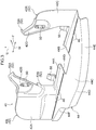
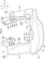
- the exterior of the sensor protector is shown in Fig. 2 through Fig. 4 .
- the sensor protector 40 of the present embodiment has a pair of mounting portions 42 that extend in the device vertical direction, a covering portion 44 that extends from the device lower end portions of the pair of mounting portions 42 toward the bumper cover 14 side (see Fig. 6 ), and a groove portion 46 that is provided at the covering portion 44.
- the sensor protector 40 is formed of a resin such as polyacetal (POM), polybutylene terephthalate (PBT) or the like.
- the mounting portions 42 are plate-shaped members that are provided as a pair in the device width direction with the sensor 30 disposed therebetween, and are a left side mounting portion 42L that is at the device width direction left side and a right side mounting portion 42R.
- the left side mounting portion 42L has an upright portion 42A that extends in the device vertical direction and is substantially L-shaped when viewed from the device rear side, and an extending portion 42B that extends toward the device upper side and width direction inner side from the upright portion 42A.
- the right side mounting portion 42R has an upright portion 42C that extends in the device vertical direction and is substantially L-shaped when viewed from the device rear side, and an extending portion 42D that extends toward the device upper side and width direction inner side from the upright portion 42C.
- each of the mounting portions 42 has a clip 50, ribs 52 and a hook 56.
- the ribs 52 are an upper rib 52A that is at the device upper side of the mounting portion 42, and a lower rib 52B that is at the device lower side.
- the clip 50 at the left side mounting portion 42L is formed so as to project-out toward the device front side at the substantial center in the device vertical direction of the extending portion 42B, at a position that is toward the device upper side of the upright portion 42A.
- the upper rib 52A at the left side mounting portion 42L is formed so as to project-out toward the device front side at the distal end of the extending portion 42B.
- the lower rib 52B at the left side mounting portion 42L is formed so as to project-out toward the device front side at the device lower side of the extending portion 42B.
- the clip 50 at the right side mounting portion 42R is formed so as to project-out toward the device front side at the device lower side of the extending portion 42D, at a position that is toward the device upper side of the upright portion 42C.
- the upper rib 52A at the right side mounting portion 42R is formed so as to project-out toward the device front side at the distal end of the extending portion 42D.
- the lower rib 52B at the right side mounting portion 42R is formed so as to project-out toward the device front side at a position that is at the device lower side with respect to the extending portion 42D.
- the clip 50 has a supporting portion 50A, which is plate-shaped and projects outward from the extending portion 42B or the extending portion 42D toward the device front side, and a holding portion 50B (see Fig. 6 ), which is substantially C-shaped with a device rear side that is open and which extends from the device front side end portion of the supporting portion 50A toward the device rear side. Further, two claw portions 50C are formed, with one above and one below the holding portion 50B.
- the holding portion 50B is formed such that the device rear side thereof is elastically deformable along the device vertical direction, and the respective claw portions 50C are formed so as to be able to approach one another in the device vertical direction.
- a mounting hole 26 is provided in the bracket 20 at a position corresponding to the clip 50.
- the sensor protector 40 is fixed to the bracket 20 due to the clips 50 being inserted through the mounting holes 26 and the claw portions 50C being anchored to the bracket 20.
- the ribs 52 (the upper rib 52A, the lower rib 52B) are set at dimensions such that they project outward from the bracket 20 toward the device front side by about 0.3 mm. Accordingly, when the clips 50 are anchored to the bracket 20, the ribs 52 move rearward 0.3 mm toward the device rear side.
- the sensor protector 40 of the present embodiment is made of resin, and, although the ribs 52 move rearward toward the device rear side, the clips 50, due to elastic force, generate a pushing force toward the device front side.
- the ribs 52 push against the bracket 20. Further, a pulling-in force toward the device rear side is generated at the clips 50 that are disposed between the upper ribs 52A and the lower ribs 52B.
- the mounting portions 42 have the pair of hooks 56 at the upright portion 42A and the upright portion 42C.
- the hook 56 at the left side mounting portion 42L is formed so as to project-out from the upright portion 42A toward the device upper side, at a substantially intermediate position between the clip 50 and the upper rib 52A in the device width direction.
- the hook 56 at the right side mounting portion 42R is formed so as to project-out from the upright portion 42C toward the device upper side, at a substantially intermediate position between the clip 50 and the upper rib 52A in the device width direction.
- the covering portion 44 is a plate-shaped member that extends from the device lower end portions of the pair of mounting portions 42 toward the bumper cover 14 side (see Fig. 6 ). Specifically, the covering portion 44 extends toward the device rear side from the device lower end portions of the upright portion 42A and the upright portion 42C of the mounting portions 42.
- the covering portion 44 has a base portion 44A as a plate portion, which extends toward the device rear side from the upright portion 42A of the mounting portion 42, and a base portion 44B as the plate portion, which extends toward the device rear side from the upright portion 42C.
- the covering portion 44 has a protecting plate portion 44C as the plate portion, which is formed continuously from the base portion 44A and the base portion 44B and extends toward the device rear side and the device lower side, and a wall portion 44E, which extends from the outer edge portion of the protecting plate portion 44C orthogonally toward the device lower side.
- the protecting plate portion 44C is in a state in which the device rear side thereof is inclined 20° with respect to the device front-rear direction (see Fig. 6 ). Further, as shown in Fig. 5 , when seen from the device upper side, the protecting plate portion 44C has an arcuate portion 44D and a cut-out portion 44F that serve as the bumper cover 14 side end portion of the covering portion 44.
- the arcuate portion 44D structures a substantially arc-shaped outer peripheral portion from the right side in the device width direction toward the left side. This arcuate portion 44D is formed along the inner wall of the bumper cover 14.
- the arcuate portion 44D has a shape that approximates the outer contour of the portion that faces the arcuate portion 44D at the inner wall of the bumper cover 14.
- the cut-out portion 44F is a shape formed by removing a portion of the arc of the arcuate portion 44D at the left side in the device width direction (the vehicle transverse direction inner side) of the arcuate portion 44D.
- the covering portion 44 has, at the device front side thereof and the device width direction central portion thereof, an open portion 44G that opens toward the device front side. Namely, when the sensor protector 40 is viewed from the device upper side, the device front side of the covering portion 44 is cut out in a substantially rectangular shape by the open portion 44G.
- the groove portions 46 are four grooves that are formed at the device upper side surface of the covering portion 44 in a row along the device width direction.
- the groove portions 46 are provided at the joined portion of the base portion 44A and the protecting plate portion 44C, and at the joined portion of the base portion 44B and the protecting plate portion 44C.
- the device width direction along which the groove portions 46 of the present embodiment are formed is a direction orthogonal to a line connecting the shortest distance between the bumper cover 14 and the back panel 12.
- the groove portions 46 of the present embodiment are formed as weak portions that make the covering portion 44 elastically deformable.
- the bracket 20 that is formed from a metal plate is fixed in advance by welding to the back panel 12 (see Fig. 5 ). Due thereto, the bracket 20 is fixed in a state of being inclined 50° with respect to the vehicle longitudinal direction.
- the sensor 30 is fixed to the bracket 20. As described above, the three corresponding bolts 22 of the bracket 20 are inserted-through the bolt holes 32 that are provided in the sensor 30, and the respective bolts 22 are screwed-together with the nuts 24. The sensor 30 is thereby fixed to the bracket 20.
- the sensor protector 40 is mounted to the bracket 20.
- the sensor protector 40 is made to approach the bracket 20 from the device lower side, and the hooks 56 are made to abut and are anchored to the device lower edge portion of the bracket 20.
- the hooks 56 anchored to the bracket 20 the device upper side of the sensor protector 40 is rotated toward the device front side, and the pair of clips 50 are inserted through the corresponding mounting holes 26.
- the pair of claw portions 50C ride-over the mounting hole 26, due to the holding portion 50B elastically deforming in a direction in which the diameter thereof decreases, the pair of claw portions 50C approach one another and pass-through the mounting hole 26. Then, after the pair of claw portions 50C pass-through the mounting hole 26, the diameter of the holding portion 50B increases, and, due thereto, the claw portions 50C are anchored to the outer edge portion of the mounting hole 26. Due thereto, the sensor protector 40 is fixed to the bracket 20. Note that a harness 34 that extends from beneath the sensor 30 is accommodated in the open portion 44G (see Fig. 2 ).
- the bumper cover 14 is mounted to the vehicle 10.
- the bumper cover 14 is fixed to, for example, the back panels 12 or a rear fender (not illustrated) or the like. Due to the bumper cover 14 being mounted, the sensors 30 and the sensor protectors 40 are accommodated at the vehicle inner side of the bumper cover 14 (see Fig. 1 ).
- the present embodiment has the following features and effects corresponding thereto.
- a first feature is that the sensor protector 40 of the present embodiment has the mounting portions 42 that are mounted to the bracket 20, the covering portion 44 that is plate-shaped and extends from the lower portions of the mounting portions 42 toward the bumper cover 14 and covers the lower portion of the sensor 30, and the groove portions 46 that are provided at the covering portion 44 and that are weak portions that make the covering portion 44 elastically deformable.
- the vehicle lower side of the bumper cover 14 of the present embodiment which is the road surface side of the sensor 30, is open. Therefore, when the sensor 30 is directly facing the road surface side, there is the concern that problems such as the following will occur. For example, there are the concerns that stones that are thrown-upward during traveling will penetrate into the interior of the bumper cover 14 and directly break the sensor 30, and that snow that swirls around at the periphery will penetrate into the interior of the bumper cover 14 and stick to the periphery of the sensor and cause malfunctioning of the sensor 30.
- the lower portion of the sensor 30 is covered by the covering portion 44, and, due thereto, the sensor 30 can be protected even if stones that are thrown-upward during traveling, or snow that swirls around at the periphery, or the like penetrate into the interior of the bumper cover 14.
- a second feature is the point that the weak portions are the groove portions 46 that are grooves that are formed along the width direction of the sensor 30.
- the groove portions 46 are formed in the device upper side surface of the covering portion 44.
- the weak portions of the present embodiment are the groove portions 46 that are four grooves that are in a row along the device width direction at the covering portion 44.
- the weak portion is not limited to this provided that a groove or grooves are formed in a direction orthogonal to the direction of a line connecting the shortest distance between the bumper cover 14 and the back panel 12.
- the weak portion may be one groove that runs along the device width direction.
- the number of grooves that form the groove portions 46 is not limited to four.
- the weak portions may be plural grooves that are provided in the covering portion 44 along the device width direction so as to be lined-up in the device front-rear direction.
- These grooves that form the weak portions are not limited to being formed in the device upper side surface, and may be formed in the device lower side surface. Moreover, in a case of providing plural grooves in the device front-rear direction, the grooves may be provided alternately at the device upper side surface and the device lower side surface.
- a third feature is the point that the arcuate portion 44D, which is the bumper cover 14 side end portion of the covering portion 44 is formed along the inner wall of the bumper cover 14.
- the covering portion 44 corresponds to the shape of the bumper cover 14
- differences in the mounting positions at the front and the rear and the left and the right, and different types of vehicles can be accommodated.
- the bracket 20 and the sensor 30 can be utilized commonly, and can be made to correspond to designs of different vehicle regions or vehicle types by preparing the sensor protectors 40 at which only the design of the covering portion 44 is changed. Due thereto, as compared with a mounting member in which a protector and a bracket for body mounting are made integral, the bracket and the protector can be made compact, and the space for storage as inventory can be reduced.
- a fourth feature is the point that the mounting portion 42 has the clip 50, which is anchored to the mounting hole 26 formed in the bracket 20, and the plural ribs 52, which stand upright from the mounting portion 42 and which push against the bracket 20 in the state in which the clip 50 is anchored to the bracket 20.
- the ribs 52 (the upper rib 52A, the lower rib 52B) are set to dimensions so as to project-out from the bracket 20 toward the device front side by about 0.3 mm. Accordingly, when the clip 50 is anchored to the bracket 20, the ribs 52 move rearward by 0.3 mm toward the device rear side and push the bracket 20.
- the sensor protector 40 of the present embodiment has the feature that it can be mounted to the vehicle 10 (the bracket 20) after the sensor 30 has been fixed to the vehicle 10. Further, because the fixing of the sensor protector 40 to the bracket 20 is carried out by the clips 50 that are made of resin, there is no need for a tool therefor. Namely, in accordance with the sensor protector 40 of the present embodiment, because the mounting of the sensor protector 40 to the vehicle 10 is easy, the number of processes at the time of manufacturing the vehicle can be reduced. Moreover, even if the sensor protector 40 breaks at the time of a collision of the vehicle 10, the replacement work is easy.
- a strip-shaped sponge may be affixed to the wall portion 44E of the covering portion 44.
- the sensor protector 40 of the present embodiment is mounted to the sensor 30 that is set at a rear corner portion of the vehicle 10 at the vehicle inner side of the bumper cover 14.
- the present embodiment is not limited to this.
- the sensor protector 40 may be mounted to a sensor that is set at a front corner portion of the vehicle 10 at the vehicle inner side of a bumper cover (not illustrated).
- the sensor 30 to which the sensor protector 40 is mounted is not limited to being set at a corner portion of the vehicle 10, and may be set at the vehicle transverse direction center.
Landscapes
- Engineering & Computer Science (AREA)
- Radar, Positioning & Navigation (AREA)
- Remote Sensing (AREA)
- Physics & Mathematics (AREA)
- Mechanical Engineering (AREA)
- Computer Networks & Wireless Communication (AREA)
- General Physics & Mathematics (AREA)
- Electromagnetism (AREA)
- Measurement Of Velocity Or Position Using Acoustic Or Ultrasonic Waves (AREA)
- Fittings On The Vehicle Exterior For Carrying Loads, And Devices For Holding Or Mounting Articles (AREA)
Abstract
Description
- The present disclosure relates to a sensor protector and a vehicle equipped therewith. Related Art
- Japanese Patent Application Laid-Open (
JP-A) No. 2007-106199 Fig. 2 ) to a bumper stay via a radar stay, at the inner side of the front bumper (bumper cover) that is made of resin. Here, in a sensor mounting structure such as that disclosed inJP-A No. 2007-106199 - To address this, there is a structure in which it is difficult for the impact of a bumper cover at the time of a vehicle collision to be transmitted to a vehicle structural member, in a case in which the lower side of the bumper cover is open and a space is provided between the bumper cover and the vehicle structural member, without the lower end portion of the bumper cover being fixed to the vehicle body. However, there is the concern that stones that are thrown-upward during traveling, or snow that swirls around at the periphery, or the like will penetrate into the bumper cover, and that the sensor will be adversely affected thereby.
- For these reasons, it is difficult to achieve both protection of the sensor and lowering of the collision force that is applied from the bumper cover to the vehicle structural member.
- An object of the present disclosure is to provide a sensor protector that can achieve both protection of a sensor and lowering of collision force that is applied from a bumper cover to a vehicle structural member.
- A sensor protector of a first aspect includes: mounting portions that are mounted to a bracket for fixing a sensor, which is provided at a vehicle inner side of a bumper cover, to a body of a vehicle; a covering portion that is plate-shaped, that extends from lower portions of the mounting portions toward the bumper cover, and that covers a lower portion of the sensor; and a weak portion that is provided at the covering portion and makes the covering portion elastically deformable.
- In accordance with the sensor protector of the first aspect, even in a case in which the lower side of a bumper cover is open and a space is provided between the bumper cover and the vehicle structural member, the lower portion of the sensor is covered by the covering portion. Due thereto, the sensor can be protected even if stones that are thrown-upward during traveling, or snow that swirls around at the periphery, or the like penetrates into the interior of the bumper cover. Further, even in a case in which the amount of deformation of the bumper cover is large and the inner wall of the bumper cover contacts the sensor protector, because the covering portion deforms due to the weak portion, it is difficult for the impact of the bumper cover to be transmitted to the vehicle structural member. As described above, in accordance with the sensor protector of the first aspect, both protecting of the sensor and decreasing of the collision force that is applied from the bumper cover to the vehicle structural member can be achieved.
- In a sensor protector of a second aspect, the weak portion comprises a groove that is formed along a width direction of the sensor.
- In accordance with the sensor protector of the second aspect, a reduction in the collision force that is applied from the bumper cover to the vehicle structural member can be achieved by the simple structure of merely providing a groove.
- In a sensor protector of a third aspect, an end portion of the covering portion at a bumper cover side has a shape that corresponds to the shape of an inner wall of the bumper cover.
- Here, "a shape that runs along an inner wall of the bumper cover" means a shape that approximates the outer contour of the portion, which faces the end portion of the covering portion, at the inner wall of the bumper cover. In accordance with the sensor protector of the third aspect, by making the covering portion correspond to the shape of the bumper cover, differences in the mounting positions at the front and the rear and the left and the right, and different types of vehicles, can be accommodated.
- In a sensor protector of a fourth aspect, each of the mounting portions has a clip that is anchored to a hole formed in the bracket, and plural ribs that stand upright from the mounting portion, and that push against the bracket in a state in which the clip is anchored to the bracket.
- In accordance with the sensor protector of the fourth aspect, by providing a region that pushes against the bracket, the occurrence of rattling at the bracket can be suppressed.
- A vehicle of a fifth aspect includes: the sensor protector of any one of the first through fourth aspects; the sensor; the bracket which is fixed to the vehicle body; and the bumper cover which is open at a road surface side of the sensor.
- In accordance with the vehicle of the fifth aspect, due to the lower portion of the sensor being covered by the covering portion, the sensor can be protected even if stones that are thrown-upward during traveling, or snow that swirls around at the periphery, or the like penetrates into the interior of the bumper cover. Further, because a space is provided between the bumper cover and the vehicle structural member, it is difficult for impact of the bumper cover to be transmitted to the vehicle structural member at the time of a collision of the vehicle. Further, even in a case in which the amount of deformation of the bumper cover is large and the inner wall of the bumper cover contacts the sensor protector, because the covering portion deforms due to the weak portion, it is difficult for the impact of the bumper cover to be transmitted to the vehicle structural member. As described above, in accordance with the vehicle of the fifth aspect, both protecting of the sensor and decreasing of the collision force that is applied from the bumper cover to the vehicle structural member can be achieved.
- In accordance with the present disclosure, both protecting of the sensor and decreasing of the collision force that is applied from the bumper cover to the vehicle structural member can be achieved.
- Exemplary embodiments of the present disclosure will be described in detail based on the following figures, wherein:
-
Fig. 1 is a rear perspective view of a vehicle to which a sensor protector relating to an embodiment of the present disclosure is mounted; -
Fig. 2 is a rear view of a sensor, a bracket, and the sensor protector relating to the embodiment of the present disclosure; -
Fig. 3 is a perspective view, which is seen from a device rear side, of the sensor protector relating to the embodiment of the present disclosure; -
Fig. 4 is a perspective view, which is seen from a device front side, of the sensor protector relating to the embodiment of the present disclosure; -
Fig. 5 is a plan sectional view (a cross-sectional view along line A-A ofFig. 2 ) of the sensor protector relating to the embodiment of the present disclosure; and -
Fig. 6 is a side sectional view (a cross-sectional view along line B-B ofFig. 2 ) of the sensor protector relating to the embodiment of the present disclosure. - A
vehicle 10, to which asensor protector 40 relating to an embodiment of the present disclosure is mounted, is described hereinafter by usingFig. 1 . Thesensor protector 40 is described by usingFig. 2 through Fig. 6 . Note that, inFig. 1 , arrow FR indicates the vehicle forward direction, arrow UP indicates the vehicle upward direction, and arrow RH indicates the vehicle transverse direction right side. Further, inFig. 2 through Fig. 6 , arrow F indicates the device frontward direction, arrow U indicates the device upward direction, and arrow W indicates the device width direction. - A
sensor 30, which is an example of a sensing device for sensing obstacles at the periphery of the vehicle, is mounted to thevehicle 10 relating to the present embodiment at a corner portion of the vehicle.Fig. 1 shows thesensor 30 that is at the vehicle right rear side. Thesensor 30 is provided at the vehicle inner side of abumper cover 14, and is fixed to abracket 20 that is formed by a metal plate. Thebracket 20 is fixed (seeFig. 2 ) by welding to aback panel 12 that serves as a vehicle structural member that structures the vehicle body. To describe this further, as shown inFig. 2 , threebolts 22, which are formed so as to project-out from the device rear side surface of thebracket 20, are provided at thebracket 20. Thebolts 22 are formed at three places that are the device width direction both ends and the device upper side end portion of thesensor 30. The threebolts 22 are inserted-throughbolt holes 32 that correspond respectively thereto, and are screwed-together withnuts 24. Due thereto, thesensor 30 is fixed to thebracket 20. - The
sensor 30 that is mounted to the vehicle right rear side in the present embodiment is fixed to thevehicle 10 in a state in which a transmitting/receivingsurface 30A of thesensor 30 is in a state of being inclined 50° (the angle from arrow X to arrow Y inFig. 5 ) with respect to the vehicle longitudinal direction. Thesensor 30 can sense obstacles by emitting radio waves (millimeter waves) from the transmitting/receivingsurface 30A and receiving radio waves that have been reflected back from obstacles. - Here, the road surface side, i.e., the vehicle lower side, of the
bumper cover 14 of thevehicle 10 of the present embodiment is open with respect to thesensor 30. Namely, at the vehicle lower side, a space is provided between thebumper cover 14 and the back panel 12 (seeFig. 6 ). Therefore, thesensor protector 40 is provided so that stones that are thrown-upward during traveling, or snow that swirls around at the periphery, or the like do not penetrate in from the vehicle lower side with respect to thesensor 30. Details of thesensor protector 40 are described hereinafter. - The exterior of the sensor protector is shown in
Fig. 2 through Fig. 4 . - As shown in
Fig. 2 andFig. 3 , thesensor protector 40 of the present embodiment has a pair of mountingportions 42 that extend in the device vertical direction, acovering portion 44 that extends from the device lower end portions of the pair of mountingportions 42 toward thebumper cover 14 side (seeFig. 6 ), and agroove portion 46 that is provided at thecovering portion 44. Thesensor protector 40 is formed of a resin such as polyacetal (POM), polybutylene terephthalate (PBT) or the like. - As shown in
Fig. 2 , themounting portions 42 are plate-shaped members that are provided as a pair in the device width direction with thesensor 30 disposed therebetween, and are a leftside mounting portion 42L that is at the device width direction left side and a rightside mounting portion 42R. The leftside mounting portion 42L has anupright portion 42A that extends in the device vertical direction and is substantially L-shaped when viewed from the device rear side, and an extendingportion 42B that extends toward the device upper side and width direction inner side from theupright portion 42A. Further, the rightside mounting portion 42R has anupright portion 42C that extends in the device vertical direction and is substantially L-shaped when viewed from the device rear side, and an extendingportion 42D that extends toward the device upper side and width direction inner side from theupright portion 42C. - Further, as shown in
Fig. 2 andFig. 4 , each of the mountingportions 42 has aclip 50,ribs 52 and ahook 56. Theribs 52 are anupper rib 52A that is at the device upper side of the mountingportion 42, and alower rib 52B that is at the device lower side. - Concretely, the
clip 50 at the leftside mounting portion 42L is formed so as to project-out toward the device front side at the substantial center in the device vertical direction of the extendingportion 42B, at a position that is toward the device upper side of theupright portion 42A. Further, theupper rib 52A at the leftside mounting portion 42L is formed so as to project-out toward the device front side at the distal end of the extendingportion 42B. Thelower rib 52B at the leftside mounting portion 42L is formed so as to project-out toward the device front side at the device lower side of the extendingportion 42B. - On the other hand, the
clip 50 at the rightside mounting portion 42R is formed so as to project-out toward the device front side at the device lower side of the extendingportion 42D, at a position that is toward the device upper side of theupright portion 42C. Further, theupper rib 52A at the rightside mounting portion 42R is formed so as to project-out toward the device front side at the distal end of the extendingportion 42D. Thelower rib 52B at the rightside mounting portion 42R is formed so as to project-out toward the device front side at a position that is at the device lower side with respect to the extendingportion 42D. - As shown in
Fig. 4 , theclip 50 has a supportingportion 50A, which is plate-shaped and projects outward from the extendingportion 42B or the extendingportion 42D toward the device front side, and a holdingportion 50B (seeFig. 6 ), which is substantially C-shaped with a device rear side that is open and which extends from the device front side end portion of the supportingportion 50A toward the device rear side. Further, twoclaw portions 50C are formed, with one above and one below the holdingportion 50B. Here, as shown inFig. 6 , the holdingportion 50B is formed such that the device rear side thereof is elastically deformable along the device vertical direction, and therespective claw portions 50C are formed so as to be able to approach one another in the device vertical direction. Here, a mountinghole 26 is provided in thebracket 20 at a position corresponding to theclip 50. Thesensor protector 40 is fixed to thebracket 20 due to theclips 50 being inserted through the mountingholes 26 and theclaw portions 50C being anchored to thebracket 20. - Here, in the present embodiment, when the anchored position of the
clip 50 on thebracket 20 in the device front-rear direction is taken as a reference position, the ribs 52 (theupper rib 52A, thelower rib 52B) are set at dimensions such that they project outward from thebracket 20 toward the device front side by about 0.3 mm. Accordingly, when theclips 50 are anchored to thebracket 20, theribs 52 move rearward 0.3 mm toward the device rear side. As described above, thesensor protector 40 of the present embodiment is made of resin, and, although theribs 52 move rearward toward the device rear side, theclips 50, due to elastic force, generate a pushing force toward the device front side. Namely, in the present embodiment, in the state in which theclips 50 are anchored to thebracket 20, theribs 52 push against thebracket 20. Further, a pulling-in force toward the device rear side is generated at theclips 50 that are disposed between theupper ribs 52A and thelower ribs 52B. - The mounting
portions 42 have the pair ofhooks 56 at theupright portion 42A and theupright portion 42C. Concretely, thehook 56 at the leftside mounting portion 42L is formed so as to project-out from theupright portion 42A toward the device upper side, at a substantially intermediate position between theclip 50 and theupper rib 52A in the device width direction. Further, thehook 56 at the rightside mounting portion 42R is formed so as to project-out from theupright portion 42C toward the device upper side, at a substantially intermediate position between theclip 50 and theupper rib 52A in the device width direction. - As shown in
Fig. 3 , the coveringportion 44 is a plate-shaped member that extends from the device lower end portions of the pair of mountingportions 42 toward thebumper cover 14 side (seeFig. 6 ). Specifically, the coveringportion 44 extends toward the device rear side from the device lower end portions of theupright portion 42A and theupright portion 42C of the mountingportions 42. The coveringportion 44 has abase portion 44A as a plate portion, which extends toward the device rear side from theupright portion 42A of the mountingportion 42, and abase portion 44B as the plate portion, which extends toward the device rear side from theupright portion 42C. Further, the coveringportion 44 has a protectingplate portion 44C as the plate portion, which is formed continuously from thebase portion 44A and thebase portion 44B and extends toward the device rear side and the device lower side, and awall portion 44E, which extends from the outer edge portion of the protectingplate portion 44C orthogonally toward the device lower side. - Here, the protecting
plate portion 44C is in a state in which the device rear side thereof is inclined 20° with respect to the device front-rear direction (seeFig. 6 ). Further, as shown inFig. 5 , when seen from the device upper side, the protectingplate portion 44C has anarcuate portion 44D and a cut-outportion 44F that serve as thebumper cover 14 side end portion of the coveringportion 44. Thearcuate portion 44D structures a substantially arc-shaped outer peripheral portion from the right side in the device width direction toward the left side. Thisarcuate portion 44D is formed along the inner wall of thebumper cover 14. To describe this further, thearcuate portion 44D has a shape that approximates the outer contour of the portion that faces thearcuate portion 44D at the inner wall of thebumper cover 14. Further, the cut-outportion 44F is a shape formed by removing a portion of the arc of thearcuate portion 44D at the left side in the device width direction (the vehicle transverse direction inner side) of thearcuate portion 44D. - Further, as shown in
Fig. 3 , the coveringportion 44 has, at the device front side thereof and the device width direction central portion thereof, anopen portion 44G that opens toward the device front side. Namely, when thesensor protector 40 is viewed from the device upper side, the device front side of the coveringportion 44 is cut out in a substantially rectangular shape by theopen portion 44G. - The
groove portions 46 are four grooves that are formed at the device upper side surface of the coveringportion 44 in a row along the device width direction. Thegroove portions 46 are provided at the joined portion of thebase portion 44A and the protectingplate portion 44C, and at the joined portion of thebase portion 44B and the protectingplate portion 44C. Here, the device width direction along which thegroove portions 46 of the present embodiment are formed is a direction orthogonal to a line connecting the shortest distance between thebumper cover 14 and theback panel 12. Thegroove portions 46 of the present embodiment are formed as weak portions that make the coveringportion 44 elastically deformable. - Processes of manufacturing the
sensor 30 and thesensor protector 40 of the present embodiment, which are structured as described above, at the right rear side of the vehicle 10 (seeFig. 1 ) are described. - First, the
bracket 20 that is formed from a metal plate is fixed in advance by welding to the back panel 12 (seeFig. 5 ). Due thereto, thebracket 20 is fixed in a state of being inclined 50° with respect to the vehicle longitudinal direction. Next, as shown inFig. 2 , thesensor 30 is fixed to thebracket 20. As described above, the three correspondingbolts 22 of thebracket 20 are inserted-through the bolt holes 32 that are provided in thesensor 30, and therespective bolts 22 are screwed-together with the nuts 24. Thesensor 30 is thereby fixed to thebracket 20. - Next, as shown in
Fig. 6 , thesensor protector 40 is mounted to thebracket 20. First, thesensor protector 40 is made to approach thebracket 20 from the device lower side, and thehooks 56 are made to abut and are anchored to the device lower edge portion of thebracket 20. Then, with thehooks 56 anchored to thebracket 20, the device upper side of thesensor protector 40 is rotated toward the device front side, and the pair ofclips 50 are inserted through the corresponding mounting holes 26. - Here, at the time when the pair of
claw portions 50C ride-over the mountinghole 26, due to the holdingportion 50B elastically deforming in a direction in which the diameter thereof decreases, the pair ofclaw portions 50C approach one another and pass-through the mountinghole 26. Then, after the pair ofclaw portions 50C pass-through the mountinghole 26, the diameter of the holdingportion 50B increases, and, due thereto, theclaw portions 50C are anchored to the outer edge portion of the mountinghole 26. Due thereto, thesensor protector 40 is fixed to thebracket 20. Note that aharness 34 that extends from beneath thesensor 30 is accommodated in theopen portion 44G (seeFig. 2 ). - Similarly, after the
sensor 30 and thesensor protector 40 are mounted to the left rear side of thevehicle 10 as well, thebumper cover 14 is mounted to thevehicle 10. Thebumper cover 14 is fixed to, for example, theback panels 12 or a rear fender (not illustrated) or the like. Due to thebumper cover 14 being mounted, thesensors 30 and thesensor protectors 40 are accommodated at the vehicle inner side of the bumper cover 14 (seeFig. 1 ). - As described above, the present embodiment has the following features and effects corresponding thereto.
- A first feature is that the
sensor protector 40 of the present embodiment has the mountingportions 42 that are mounted to thebracket 20, the coveringportion 44 that is plate-shaped and extends from the lower portions of the mountingportions 42 toward thebumper cover 14 and covers the lower portion of thesensor 30, and thegroove portions 46 that are provided at the coveringportion 44 and that are weak portions that make the coveringportion 44 elastically deformable. - Here, the vehicle lower side of the
bumper cover 14 of the present embodiment, which is the road surface side of thesensor 30, is open. Therefore, when thesensor 30 is directly facing the road surface side, there is the concern that problems such as the following will occur. For example, there are the concerns that stones that are thrown-upward during traveling will penetrate into the interior of thebumper cover 14 and directly break thesensor 30, and that snow that swirls around at the periphery will penetrate into the interior of thebumper cover 14 and stick to the periphery of the sensor and cause malfunctioning of thesensor 30. To address this, in accordance with the above-described first feature, the lower portion of thesensor 30 is covered by the coveringportion 44, and, due thereto, thesensor 30 can be protected even if stones that are thrown-upward during traveling, or snow that swirls around at the periphery, or the like penetrate into the interior of thebumper cover 14. - In the present embodiment, because a space is provided between the
bumper cover 14 and theback panel 12 that serves as a vehicle structural member, at the time of a collision of thevehicle 10, it is difficult for the impact of thebumper cover 14 to be transmitted to theback panel 12. However, in the case of a mounting member in which a bracket for body mounting and a protector that covers the periphery of the sensor are made integral, there are cases in which the vehicle body deforms when the mounting member itself is pushed toward the vehicle inner side accompanying the deformation of the bumper cover, even if the collision is a light collision. Accordingly, in the case of a mounting member in which the bracket and the protector are made integral, at the time of a collision of thevehicle 10, there are cases in which repair costs not only for the bumper cover, but also for the vehicle body, are additionally incurred. To address this, in accordance with the first feature, even if the amount of deformation of the body is large and the inner wall of thebumper cover 14 contacts thesensor protector 40, the coveringportion 44 deforms due to thegroove portions 46 that serve as weak portions, and therefore, it is difficult for impact of thebumper cover 14 to be transmitted to theback panel 12. As described above, in accordance with the first feature, both protection of thesensor 30 and lowering of the collision force that thebumper cover 14 applies to theback panel 12 can be achieved. - A second feature is the point that the weak portions are the
groove portions 46 that are grooves that are formed along the width direction of thesensor 30. In the present embodiment, thegroove portions 46 are formed in the device upper side surface of the coveringportion 44. In accordance with this second feature, a reduction in the collision force that thebumper cover 14 applies to theback panel 12 can be devised by the simple structure of merely providing the grooves. - Note that the weak portions of the present embodiment are the
groove portions 46 that are four grooves that are in a row along the device width direction at the coveringportion 44. However, the weak portion is not limited to this provided that a groove or grooves are formed in a direction orthogonal to the direction of a line connecting the shortest distance between thebumper cover 14 and theback panel 12. For example, the weak portion may be one groove that runs along the device width direction. Further, the number of grooves that form thegroove portions 46 is not limited to four. For example, the weak portions may be plural grooves that are provided in the coveringportion 44 along the device width direction so as to be lined-up in the device front-rear direction. These grooves that form the weak portions are not limited to being formed in the device upper side surface, and may be formed in the device lower side surface. Moreover, in a case of providing plural grooves in the device front-rear direction, the grooves may be provided alternately at the device upper side surface and the device lower side surface. - A third feature is the point that the
arcuate portion 44D, which is thebumper cover 14 side end portion of the coveringportion 44 is formed along the inner wall of thebumper cover 14. In accordance with the third feature, by making the coveringportion 44 correspond to the shape of thebumper cover 14, differences in the mounting positions at the front and the rear and the left and the right, and different types of vehicles, can be accommodated. Namely, thebracket 20 and thesensor 30 can be utilized commonly, and can be made to correspond to designs of different vehicle regions or vehicle types by preparing thesensor protectors 40 at which only the design of the coveringportion 44 is changed. Due thereto, as compared with a mounting member in which a protector and a bracket for body mounting are made integral, the bracket and the protector can be made compact, and the space for storage as inventory can be reduced. - A fourth feature is the point that the mounting
portion 42 has theclip 50, which is anchored to the mountinghole 26 formed in thebracket 20, and theplural ribs 52, which stand upright from the mountingportion 42 and which push against thebracket 20 in the state in which theclip 50 is anchored to thebracket 20. As described above, when the anchored position of theclip 50 on thebracket 20 in the device front-rear direction is considered to be a reference position, the ribs 52 (theupper rib 52A, thelower rib 52B) are set to dimensions so as to project-out from thebracket 20 toward the device front side by about 0.3 mm. Accordingly, when theclip 50 is anchored to thebracket 20, theribs 52 move rearward by 0.3 mm toward the device rear side and push thebracket 20. Further, pulling-in force toward the device rear side arises at theclip 50 that is disposed between theupper rib 52A and thelower rib 52B. In this way, in accordance with the fourth feature, by providing a region that pushes against thebracket 20, the occurrence of rattling at thebracket 20 can be suppressed. - In addition, the
sensor protector 40 of the present embodiment has the feature that it can be mounted to the vehicle 10 (the bracket 20) after thesensor 30 has been fixed to thevehicle 10. Further, because the fixing of thesensor protector 40 to thebracket 20 is carried out by theclips 50 that are made of resin, there is no need for a tool therefor. Namely, in accordance with thesensor protector 40 of the present embodiment, because the mounting of thesensor protector 40 to thevehicle 10 is easy, the number of processes at the time of manufacturing the vehicle can be reduced. Moreover, even if thesensor protector 40 breaks at the time of a collision of thevehicle 10, the replacement work is easy. - Note that, at the time of mounting the
sensor protector 40 to thebracket 20, in a case in which the gap between the coveringportion 44 and thebumper cover 14 is large, or in a case in which it is desired to further mitigate impact from thebumper cover 14, a strip-shaped sponge may be affixed to thewall portion 44E of the coveringportion 44. - The
sensor protector 40 of the present embodiment is mounted to thesensor 30 that is set at a rear corner portion of thevehicle 10 at the vehicle inner side of thebumper cover 14. However, the present embodiment is not limited to this. For example, thesensor protector 40 may be mounted to a sensor that is set at a front corner portion of thevehicle 10 at the vehicle inner side of a bumper cover (not illustrated). Further, thesensor 30 to which thesensor protector 40 is mounted is not limited to being set at a corner portion of thevehicle 10, and may be set at the vehicle transverse direction center. - Although an embodiment of the present disclosure has been described above, the present disclosure is not limited to the above, and, of course, can be implemented by being modified in various ways other than the above within a scope that does not depart from the gist thereof.
Claims (8)
- A sensor protector, comprising:mounting portions (42) that are mounted to a bracket (20) for fixing a sensor (30), which is provided at a vehicle inner side of a bumper cover (14), to a body of a vehicle;a covering portion (44) that is plate-shaped, that extends from lower portions of the mounting portions toward the bumper cover, and that covers a lower portion of the sensor; anda weak portion (46) that is provided at the covering portion and makes the covering portion elastically deformable.
- The sensor protector of claim 1, wherein the weak portion comprises a groove that is formed along a width direction of the sensor.
- The sensor protector of claim 1 or claim 2, wherein an end portion of the covering portion at a bumper cover side has a shape that corresponds to the shape of an inner wall of the bumper cover.
- The sensor protector of any one of claims 1 through 3, wherein each of the mounting portions has:a clip (50) that is anchored to a hole formed in the bracket, anda plurality of ribs (52) that stand upright from the mounting portion, and that push against the bracket in a state in which the clip is anchored to the bracket.
- The sensor protector of any one of claims 1 through 4, wherein the mounting portions have plate-shaped members that are provided as a pair in a width direction of the sensor with the sensor disposed therebetween.
- The sensor protector of any one of claims 1 through 5, wherein the covering portion has, at a central portion thereof in a width direction of the sensor, an open portion (44G) that opens at a sensor side.
- The sensor protector of any one of claims 1 through 6, wherein the covering portion has:a plate portion (44A,44B,44C) that extends from the mounting portions toward a rear side of the sensor, anda wall portion (44E) that extends from the plate portion toward a lower side of the sensor.
- A vehicle, comprising:the sensor protector of any one of claims 1 through 7;the sensor (30);the bracket (20), which is fixed to the body of the vehicle; andthe bumper cover (14), which is open at a road surface side of the sensor.
Applications Claiming Priority (1)
| Application Number | Priority Date | Filing Date | Title |
|---|---|---|---|
| JP2017190973A JP6863209B2 (en) | 2017-09-29 | 2017-09-29 | Sensor protector and vehicle equipped with it |
Publications (2)
| Publication Number | Publication Date |
|---|---|
| EP3461692A1 true EP3461692A1 (en) | 2019-04-03 |
| EP3461692B1 EP3461692B1 (en) | 2020-01-22 |
Family
ID=63442512
Family Applications (1)
| Application Number | Title | Priority Date | Filing Date |
|---|---|---|---|
| EP18191246.0A Active EP3461692B1 (en) | 2017-09-29 | 2018-08-28 | Sensor protector and vehicle equipped therewith |
Country Status (4)
| Country | Link |
|---|---|
| US (1) | US10518728B2 (en) |
| EP (1) | EP3461692B1 (en) |
| JP (1) | JP6863209B2 (en) |
| CN (1) | CN109572608B (en) |
Cited By (1)
| Publication number | Priority date | Publication date | Assignee | Title |
|---|---|---|---|---|
| WO2022229525A1 (en) | 2021-04-28 | 2022-11-03 | Psa Automobiles Sa | Sacrificial fastening device for a sensor |
Families Citing this family (9)
| Publication number | Priority date | Publication date | Assignee | Title |
|---|---|---|---|---|
| JP7102947B2 (en) | 2018-05-29 | 2022-07-20 | トヨタ自動車株式会社 | Sensor protector and vehicle equipped with it |
| JP7035938B2 (en) | 2018-09-27 | 2022-03-15 | トヨタ自動車株式会社 | Sensor protector |
| EP3718831A1 (en) | 2019-04-05 | 2020-10-07 | The Raymond Corporation | Material handling vehicle having a multi-piece bumper assembly |
| JP6842512B2 (en) * | 2019-07-31 | 2021-03-17 | 本田技研工業株式会社 | Rear structure of the car body |
| JP7312376B2 (en) * | 2019-09-02 | 2023-07-21 | スズキ株式会社 | Vehicle sensor mounting structure |
| DE102019134861B4 (en) * | 2019-12-18 | 2022-03-10 | Audi Ag | Sensor arrangement on a vehicle |
| DE102020103152B4 (en) | 2020-02-07 | 2025-09-04 | Webasto SE | Roof module for a motor vehicle, comprising sensor module with housing |
| JP7390243B2 (en) * | 2020-04-17 | 2023-12-01 | 株式会社ニフコ | Bracket for automotive equipment |
| JP2022158504A (en) * | 2021-04-02 | 2022-10-17 | トヨタ自動車株式会社 | vehicle structure |
Citations (4)
| Publication number | Priority date | Publication date | Assignee | Title |
|---|---|---|---|---|
| JP2007106199A (en) | 2005-10-12 | 2007-04-26 | Mitsuba Corp | Vehicle periphery monitor device |
| EP2008876A2 (en) * | 2007-06-27 | 2008-12-31 | Nissan Motor Co., Ltd. | Mounting structure for vehicle crash sensor |
| US20140111950A1 (en) * | 2012-10-19 | 2014-04-24 | Toyota Motor Engineering & Manufacturing North America, Inc. | Blind spot monitor assembly |
| WO2016098486A1 (en) * | 2014-12-18 | 2016-06-23 | オートリブ ディベロップメント エービー | Vehicle radar device |
Family Cites Families (23)
| Publication number | Priority date | Publication date | Assignee | Title |
|---|---|---|---|---|
| JP3960459B2 (en) * | 2001-03-12 | 2007-08-15 | 本田技研工業株式会社 | Ranging sensor mounting structure |
| DE10118112A1 (en) * | 2001-04-11 | 2002-10-17 | Dynamit Nobel Kunststoff Gmbh | Holder for a component with small dimensions on a bumper |
| US20040066618A1 (en) * | 2002-08-01 | 2004-04-08 | Layton Michael R. | Shock-resistant enclosure |
| DE102004021005A1 (en) * | 2004-04-20 | 2005-11-24 | Decoma (Germany) Gmbh | Holding device for a sensor |
| JP4839587B2 (en) * | 2004-08-02 | 2011-12-21 | 株式会社デンソー | Ultrasonic sensor mounting structure |
| JP2007142967A (en) * | 2005-11-21 | 2007-06-07 | Denso Corp | Ultrasonic sensor |
| JP4742923B2 (en) * | 2006-03-15 | 2011-08-10 | 株式会社デンソー | Ultrasonic sensor |
| JP4513833B2 (en) * | 2007-07-17 | 2010-07-28 | 株式会社デンソー | Vehicle collision detection device |
| US7506906B1 (en) * | 2008-07-22 | 2009-03-24 | Honda Motor Co., Ltd. | Vehicle bumper assembly |
| DE102008057432A1 (en) * | 2008-11-07 | 2010-05-12 | Dr.Ing.H.C.F.Porsche Aktiengesellschaft | Arrangement of a headlight pot, a sensor and a protective plate for the sensor in a vehicle |
| CN104067139B (en) * | 2012-02-03 | 2016-05-11 | 三菱电机株式会社 | Mounting structure of ultrasonic sensor module |
| KR101890616B1 (en) * | 2012-02-20 | 2018-08-22 | 현대모비스 주식회사 | Mounting structure of sensor for vehicle |
| KR101953903B1 (en) * | 2012-07-05 | 2019-03-04 | 현대모비스 주식회사 | Mounting structure of sensor for vehicle |
| JP5920228B2 (en) * | 2013-01-09 | 2016-05-18 | トヨタ自動車株式会社 | Bumper for vehicle equipped with pedestrian collision detection device |
| JP2014205473A (en) * | 2013-04-16 | 2014-10-30 | 本田技研工業株式会社 | Vehicle front structure |
| US8894119B1 (en) * | 2013-06-12 | 2014-11-25 | Ford Global Technologies, Llc | Bonded vehicle sensor assembly |
| US8910986B1 (en) * | 2013-06-12 | 2014-12-16 | Ford Global Technologies, Llc | Bonded and rotatable vehicle sensor assembly |
| JP6090196B2 (en) * | 2014-02-10 | 2017-03-08 | トヨタ自動車株式会社 | Bumper structure for vehicles with pedestrian collision detection sensor |
| JP6233651B2 (en) * | 2014-06-18 | 2017-11-22 | 株式会社デンソー | Vehicle collision detection device |
| US10144424B2 (en) * | 2015-04-09 | 2018-12-04 | Toyota Jidosha Kabushiki Kaisha | Arrangement structure for vicinity information detection sensor |
| JP6311685B2 (en) * | 2015-09-29 | 2018-04-18 | トヨタ自動車株式会社 | Vehicle sensor mounting structure |
| US9840216B2 (en) * | 2015-12-22 | 2017-12-12 | Darrin Dagrossa | Transparent bumper guard |
| JP6317379B2 (en) * | 2016-02-22 | 2018-04-25 | 本田技研工業株式会社 | Airbag sensor mounting structure |
-
2017
- 2017-09-29 JP JP2017190973A patent/JP6863209B2/en active Active
-
2018
- 2018-08-28 EP EP18191246.0A patent/EP3461692B1/en active Active
- 2018-09-05 CN CN201811030300.9A patent/CN109572608B/en active Active
- 2018-09-07 US US16/124,839 patent/US10518728B2/en active Active
Patent Citations (4)
| Publication number | Priority date | Publication date | Assignee | Title |
|---|---|---|---|---|
| JP2007106199A (en) | 2005-10-12 | 2007-04-26 | Mitsuba Corp | Vehicle periphery monitor device |
| EP2008876A2 (en) * | 2007-06-27 | 2008-12-31 | Nissan Motor Co., Ltd. | Mounting structure for vehicle crash sensor |
| US20140111950A1 (en) * | 2012-10-19 | 2014-04-24 | Toyota Motor Engineering & Manufacturing North America, Inc. | Blind spot monitor assembly |
| WO2016098486A1 (en) * | 2014-12-18 | 2016-06-23 | オートリブ ディベロップメント エービー | Vehicle radar device |
Cited By (2)
| Publication number | Priority date | Publication date | Assignee | Title |
|---|---|---|---|---|
| WO2022229525A1 (en) | 2021-04-28 | 2022-11-03 | Psa Automobiles Sa | Sacrificial fastening device for a sensor |
| FR3122378A1 (en) | 2021-04-28 | 2022-11-04 | Psa Automobiles Sa | Fixing device for a programmed break sensor. |
Also Published As
| Publication number | Publication date |
|---|---|
| EP3461692B1 (en) | 2020-01-22 |
| CN109572608B (en) | 2022-03-18 |
| CN109572608A (en) | 2019-04-05 |
| US20190100162A1 (en) | 2019-04-04 |
| JP6863209B2 (en) | 2021-04-21 |
| JP2019064417A (en) | 2019-04-25 |
| US10518728B2 (en) | 2019-12-31 |
Similar Documents
| Publication | Publication Date | Title |
|---|---|---|
| EP3461692B1 (en) | Sensor protector and vehicle equipped therewith | |
| EP3150445B1 (en) | Vehicle front structure provided with sensor for detecting pedestrian collision | |
| CN102791527B (en) | Mounting structure of automotive exterior parts | |
| EP2683566B1 (en) | Protective device for onboard electrical equipment | |
| KR20140074771A (en) | Frontal collision impact absorbing device for vehicle | |
| JP2011126363A (en) | Auxiliary machine guide structure during vehicle collision | |
| JP6401969B2 (en) | Vehicle under cover | |
| EP2106355B1 (en) | Vehicle door structure | |
| JP7200611B2 (en) | vehicle front structure | |
| JP7141998B2 (en) | Protective member and protective structure | |
| JP2019051929A (en) | Bumper cover retainers for bumper assemblies | |
| CN110893760B (en) | Vehicle underfloor structure | |
| CN109866826B (en) | Vehicle body mounting bracket for vehicle | |
| JP6710229B2 (en) | Mounting member | |
| EP1260427B1 (en) | Bracket for motor vehicle | |
| CN115038991A (en) | Support for a sensor on a vehicle structure and vehicle having such a support | |
| KR102383254B1 (en) | Front vehicle body reinforcing structure | |
| US7097221B2 (en) | Bumper having a roll-formed ridge | |
| JP4836977B2 (en) | Sensor layout | |
| JP6669152B2 (en) | Collision detection device | |
| JP7400637B2 (en) | Protection structure for electrical parts | |
| KR101807135B1 (en) | Rear floor assembly | |
| JP7039789B2 (en) | Bumper structure | |
| KR20240130453A (en) | Parking distance warning sensor holder assembly for vehicle | |
| CN104925012B (en) | The device of the bumper of automobile and the annex being connected with bumper by clip |
Legal Events
| Date | Code | Title | Description |
|---|---|---|---|
| PUAI | Public reference made under article 153(3) epc to a published international application that has entered the european phase |
Free format text: ORIGINAL CODE: 0009012 |
|
| STAA | Information on the status of an ep patent application or granted ep patent |
Free format text: STATUS: REQUEST FOR EXAMINATION WAS MADE |
|
| 17P | Request for examination filed |
Effective date: 20180828 |
|
| AK | Designated contracting states |
Kind code of ref document: A1 Designated state(s): AL AT BE BG CH CY CZ DE DK EE ES FI FR GB GR HR HU IE IS IT LI LT LU LV MC MK MT NL NO PL PT RO RS SE SI SK SM TR |
|
| AX | Request for extension of the european patent |
Extension state: BA ME |
|
| STAA | Information on the status of an ep patent application or granted ep patent |
Free format text: STATUS: EXAMINATION IS IN PROGRESS |
|
| 17Q | First examination report despatched |
Effective date: 20190514 |
|
| GRAP | Despatch of communication of intention to grant a patent |
Free format text: ORIGINAL CODE: EPIDOSNIGR1 |
|
| STAA | Information on the status of an ep patent application or granted ep patent |
Free format text: STATUS: GRANT OF PATENT IS INTENDED |
|
| GRAS | Grant fee paid |
Free format text: ORIGINAL CODE: EPIDOSNIGR3 |
|
| INTG | Intention to grant announced |
Effective date: 20191111 |
|
| GRAA | (expected) grant |
Free format text: ORIGINAL CODE: 0009210 |
|
| STAA | Information on the status of an ep patent application or granted ep patent |
Free format text: STATUS: THE PATENT HAS BEEN GRANTED |
|
| AK | Designated contracting states |
Kind code of ref document: B1 Designated state(s): AL AT BE BG CH CY CZ DE DK EE ES FI FR GB GR HR HU IE IS IT LI LT LU LV MC MK MT NL NO PL PT RO RS SE SI SK SM TR |
|
| REG | Reference to a national code |
Ref country code: GB Ref legal event code: FG4D |
|
| REG | Reference to a national code |
Ref country code: CH Ref legal event code: EP |
|
| REG | Reference to a national code |
Ref country code: AT Ref legal event code: REF Ref document number: 1226728 Country of ref document: AT Kind code of ref document: T Effective date: 20200215 |
|
| REG | Reference to a national code |
Ref country code: IE Ref legal event code: FG4D |
|
| REG | Reference to a national code |
Ref country code: DE Ref legal event code: R096 Ref document number: 602018002116 Country of ref document: DE |
|
| REG | Reference to a national code |
Ref country code: NL Ref legal event code: MP Effective date: 20200122 |
|
| REG | Reference to a national code |
Ref country code: LT Ref legal event code: MG4D |
|
| PG25 | Lapsed in a contracting state [announced via postgrant information from national office to epo] |
Ref country code: FI Free format text: LAPSE BECAUSE OF FAILURE TO SUBMIT A TRANSLATION OF THE DESCRIPTION OR TO PAY THE FEE WITHIN THE PRESCRIBED TIME-LIMIT Effective date: 20200122 Ref country code: RS Free format text: LAPSE BECAUSE OF FAILURE TO SUBMIT A TRANSLATION OF THE DESCRIPTION OR TO PAY THE FEE WITHIN THE PRESCRIBED TIME-LIMIT Effective date: 20200122 Ref country code: PT Free format text: LAPSE BECAUSE OF FAILURE TO SUBMIT A TRANSLATION OF THE DESCRIPTION OR TO PAY THE FEE WITHIN THE PRESCRIBED TIME-LIMIT Effective date: 20200614 Ref country code: NO Free format text: LAPSE BECAUSE OF FAILURE TO SUBMIT A TRANSLATION OF THE DESCRIPTION OR TO PAY THE FEE WITHIN THE PRESCRIBED TIME-LIMIT Effective date: 20200422 Ref country code: NL Free format text: LAPSE BECAUSE OF FAILURE TO SUBMIT A TRANSLATION OF THE DESCRIPTION OR TO PAY THE FEE WITHIN THE PRESCRIBED TIME-LIMIT Effective date: 20200122 |
|
| PG25 | Lapsed in a contracting state [announced via postgrant information from national office to epo] |
Ref country code: LV Free format text: LAPSE BECAUSE OF FAILURE TO SUBMIT A TRANSLATION OF THE DESCRIPTION OR TO PAY THE FEE WITHIN THE PRESCRIBED TIME-LIMIT Effective date: 20200122 Ref country code: IS Free format text: LAPSE BECAUSE OF FAILURE TO SUBMIT A TRANSLATION OF THE DESCRIPTION OR TO PAY THE FEE WITHIN THE PRESCRIBED TIME-LIMIT Effective date: 20200522 Ref country code: SE Free format text: LAPSE BECAUSE OF FAILURE TO SUBMIT A TRANSLATION OF THE DESCRIPTION OR TO PAY THE FEE WITHIN THE PRESCRIBED TIME-LIMIT Effective date: 20200122 Ref country code: BG Free format text: LAPSE BECAUSE OF FAILURE TO SUBMIT A TRANSLATION OF THE DESCRIPTION OR TO PAY THE FEE WITHIN THE PRESCRIBED TIME-LIMIT Effective date: 20200422 Ref country code: GR Free format text: LAPSE BECAUSE OF FAILURE TO SUBMIT A TRANSLATION OF THE DESCRIPTION OR TO PAY THE FEE WITHIN THE PRESCRIBED TIME-LIMIT Effective date: 20200423 Ref country code: HR Free format text: LAPSE BECAUSE OF FAILURE TO SUBMIT A TRANSLATION OF THE DESCRIPTION OR TO PAY THE FEE WITHIN THE PRESCRIBED TIME-LIMIT Effective date: 20200122 |
|
| REG | Reference to a national code |
Ref country code: DE Ref legal event code: R097 Ref document number: 602018002116 Country of ref document: DE |
|
| PG25 | Lapsed in a contracting state [announced via postgrant information from national office to epo] |
Ref country code: EE Free format text: LAPSE BECAUSE OF FAILURE TO SUBMIT A TRANSLATION OF THE DESCRIPTION OR TO PAY THE FEE WITHIN THE PRESCRIBED TIME-LIMIT Effective date: 20200122 Ref country code: SM Free format text: LAPSE BECAUSE OF FAILURE TO SUBMIT A TRANSLATION OF THE DESCRIPTION OR TO PAY THE FEE WITHIN THE PRESCRIBED TIME-LIMIT Effective date: 20200122 Ref country code: LT Free format text: LAPSE BECAUSE OF FAILURE TO SUBMIT A TRANSLATION OF THE DESCRIPTION OR TO PAY THE FEE WITHIN THE PRESCRIBED TIME-LIMIT Effective date: 20200122 Ref country code: DK Free format text: LAPSE BECAUSE OF FAILURE TO SUBMIT A TRANSLATION OF THE DESCRIPTION OR TO PAY THE FEE WITHIN THE PRESCRIBED TIME-LIMIT Effective date: 20200122 Ref country code: SK Free format text: LAPSE BECAUSE OF FAILURE TO SUBMIT A TRANSLATION OF THE DESCRIPTION OR TO PAY THE FEE WITHIN THE PRESCRIBED TIME-LIMIT Effective date: 20200122 Ref country code: ES Free format text: LAPSE BECAUSE OF FAILURE TO SUBMIT A TRANSLATION OF THE DESCRIPTION OR TO PAY THE FEE WITHIN THE PRESCRIBED TIME-LIMIT Effective date: 20200122 Ref country code: RO Free format text: LAPSE BECAUSE OF FAILURE TO SUBMIT A TRANSLATION OF THE DESCRIPTION OR TO PAY THE FEE WITHIN THE PRESCRIBED TIME-LIMIT Effective date: 20200122 Ref country code: CZ Free format text: LAPSE BECAUSE OF FAILURE TO SUBMIT A TRANSLATION OF THE DESCRIPTION OR TO PAY THE FEE WITHIN THE PRESCRIBED TIME-LIMIT Effective date: 20200122 |
|
| REG | Reference to a national code |
Ref country code: AT Ref legal event code: MK05 Ref document number: 1226728 Country of ref document: AT Kind code of ref document: T Effective date: 20200122 |
|
| PLBE | No opposition filed within time limit |
Free format text: ORIGINAL CODE: 0009261 |
|
| STAA | Information on the status of an ep patent application or granted ep patent |
Free format text: STATUS: NO OPPOSITION FILED WITHIN TIME LIMIT |
|
| 26N | No opposition filed |
Effective date: 20201023 |
|
| PG25 | Lapsed in a contracting state [announced via postgrant information from national office to epo] |
Ref country code: IT Free format text: LAPSE BECAUSE OF FAILURE TO SUBMIT A TRANSLATION OF THE DESCRIPTION OR TO PAY THE FEE WITHIN THE PRESCRIBED TIME-LIMIT Effective date: 20200122 Ref country code: AT Free format text: LAPSE BECAUSE OF FAILURE TO SUBMIT A TRANSLATION OF THE DESCRIPTION OR TO PAY THE FEE WITHIN THE PRESCRIBED TIME-LIMIT Effective date: 20200122 |
|
| PG25 | Lapsed in a contracting state [announced via postgrant information from national office to epo] |
Ref country code: SI Free format text: LAPSE BECAUSE OF FAILURE TO SUBMIT A TRANSLATION OF THE DESCRIPTION OR TO PAY THE FEE WITHIN THE PRESCRIBED TIME-LIMIT Effective date: 20200122 Ref country code: PL Free format text: LAPSE BECAUSE OF FAILURE TO SUBMIT A TRANSLATION OF THE DESCRIPTION OR TO PAY THE FEE WITHIN THE PRESCRIBED TIME-LIMIT Effective date: 20200122 |
|
| PG25 | Lapsed in a contracting state [announced via postgrant information from national office to epo] |
Ref country code: MC Free format text: LAPSE BECAUSE OF FAILURE TO SUBMIT A TRANSLATION OF THE DESCRIPTION OR TO PAY THE FEE WITHIN THE PRESCRIBED TIME-LIMIT Effective date: 20200122 |
|
| PG25 | Lapsed in a contracting state [announced via postgrant information from national office to epo] |
Ref country code: LU Free format text: LAPSE BECAUSE OF NON-PAYMENT OF DUE FEES Effective date: 20200828 |
|
| REG | Reference to a national code |
Ref country code: BE Ref legal event code: MM Effective date: 20200831 |
|
| REG | Reference to a national code |
Ref country code: DE Ref legal event code: R084 Ref document number: 602018002116 Country of ref document: DE |
|
| PG25 | Lapsed in a contracting state [announced via postgrant information from national office to epo] |
Ref country code: BE Free format text: LAPSE BECAUSE OF NON-PAYMENT OF DUE FEES Effective date: 20200831 Ref country code: IE Free format text: LAPSE BECAUSE OF NON-PAYMENT OF DUE FEES Effective date: 20200828 |
|
| REG | Reference to a national code |
Ref country code: GB Ref legal event code: 746 Effective date: 20210929 |
|
| REG | Reference to a national code |
Ref country code: CH Ref legal event code: PL |
|
| PG25 | Lapsed in a contracting state [announced via postgrant information from national office to epo] |
Ref country code: LI Free format text: LAPSE BECAUSE OF NON-PAYMENT OF DUE FEES Effective date: 20210831 Ref country code: CH Free format text: LAPSE BECAUSE OF NON-PAYMENT OF DUE FEES Effective date: 20210831 |
|
| PG25 | Lapsed in a contracting state [announced via postgrant information from national office to epo] |
Ref country code: TR Free format text: LAPSE BECAUSE OF FAILURE TO SUBMIT A TRANSLATION OF THE DESCRIPTION OR TO PAY THE FEE WITHIN THE PRESCRIBED TIME-LIMIT Effective date: 20200122 Ref country code: MT Free format text: LAPSE BECAUSE OF FAILURE TO SUBMIT A TRANSLATION OF THE DESCRIPTION OR TO PAY THE FEE WITHIN THE PRESCRIBED TIME-LIMIT Effective date: 20200122 Ref country code: CY Free format text: LAPSE BECAUSE OF FAILURE TO SUBMIT A TRANSLATION OF THE DESCRIPTION OR TO PAY THE FEE WITHIN THE PRESCRIBED TIME-LIMIT Effective date: 20200122 |
|
| PG25 | Lapsed in a contracting state [announced via postgrant information from national office to epo] |
Ref country code: MK Free format text: LAPSE BECAUSE OF FAILURE TO SUBMIT A TRANSLATION OF THE DESCRIPTION OR TO PAY THE FEE WITHIN THE PRESCRIBED TIME-LIMIT Effective date: 20200122 Ref country code: AL Free format text: LAPSE BECAUSE OF FAILURE TO SUBMIT A TRANSLATION OF THE DESCRIPTION OR TO PAY THE FEE WITHIN THE PRESCRIBED TIME-LIMIT Effective date: 20200122 |
|
| P01 | Opt-out of the competence of the unified patent court (upc) registered |
Effective date: 20230427 |
|
| PGFP | Annual fee paid to national office [announced via postgrant information from national office to epo] |
Ref country code: DE Payment date: 20250702 Year of fee payment: 8 |
|
| PGFP | Annual fee paid to national office [announced via postgrant information from national office to epo] |
Ref country code: GB Payment date: 20250703 Year of fee payment: 8 |
|
| PGFP | Annual fee paid to national office [announced via postgrant information from national office to epo] |
Ref country code: FR Payment date: 20250703 Year of fee payment: 8 |