EP3461647A1 - Tape and tape cassette - Google Patents
Tape and tape cassette Download PDFInfo
- Publication number
- EP3461647A1 EP3461647A1 EP18193240.1A EP18193240A EP3461647A1 EP 3461647 A1 EP3461647 A1 EP 3461647A1 EP 18193240 A EP18193240 A EP 18193240A EP 3461647 A1 EP3461647 A1 EP 3461647A1
- Authority
- EP
- European Patent Office
- Prior art keywords
- marker
- markers
- tape
- label
- labels
- Prior art date
- Legal status (The legal status is an assumption and is not a legal conclusion. Google has not performed a legal analysis and makes no representation as to the accuracy of the status listed.)
- Granted
Links
Images



Classifications
-
- B—PERFORMING OPERATIONS; TRANSPORTING
- B41—PRINTING; LINING MACHINES; TYPEWRITERS; STAMPS
- B41J—TYPEWRITERS; SELECTIVE PRINTING MECHANISMS, i.e. MECHANISMS PRINTING OTHERWISE THAN FROM A FORME; CORRECTION OF TYPOGRAPHICAL ERRORS
- B41J11/00—Devices or arrangements of selective printing mechanisms, e.g. ink-jet printers or thermal printers, for supporting or handling copy material in sheet or web form
- B41J11/36—Blanking or long feeds; Feeding to a particular line, e.g. by rotation of platen or feed roller
- B41J11/42—Controlling printing material conveyance for accurate alignment of the printing material with the printhead; Print registering
-
- B—PERFORMING OPERATIONS; TRANSPORTING
- B65—CONVEYING; PACKING; STORING; HANDLING THIN OR FILAMENTARY MATERIAL
- B65C—LABELLING OR TAGGING MACHINES, APPARATUS, OR PROCESSES
- B65C9/00—Details of labelling machines or apparatus
- B65C9/40—Controls; Safety devices
- B65C9/42—Label feed control
- B65C9/44—Label feed control by special means responsive to marks on labels or articles
-
- B—PERFORMING OPERATIONS; TRANSPORTING
- B41—PRINTING; LINING MACHINES; TYPEWRITERS; STAMPS
- B41J—TYPEWRITERS; SELECTIVE PRINTING MECHANISMS, i.e. MECHANISMS PRINTING OTHERWISE THAN FROM A FORME; CORRECTION OF TYPOGRAPHICAL ERRORS
- B41J11/00—Devices or arrangements of selective printing mechanisms, e.g. ink-jet printers or thermal printers, for supporting or handling copy material in sheet or web form
- B41J11/36—Blanking or long feeds; Feeding to a particular line, e.g. by rotation of platen or feed roller
- B41J11/42—Controlling printing material conveyance for accurate alignment of the printing material with the printhead; Print registering
- B41J11/46—Controlling printing material conveyance for accurate alignment of the printing material with the printhead; Print registering by marks or formations on the paper being fed
-
- B—PERFORMING OPERATIONS; TRANSPORTING
- B41—PRINTING; LINING MACHINES; TYPEWRITERS; STAMPS
- B41J—TYPEWRITERS; SELECTIVE PRINTING MECHANISMS, i.e. MECHANISMS PRINTING OTHERWISE THAN FROM A FORME; CORRECTION OF TYPOGRAPHICAL ERRORS
- B41J13/00—Devices or arrangements of selective printing mechanisms, e.g. ink-jet printers or thermal printers, specially adapted for supporting or handling copy material in short lengths, e.g. sheets
- B41J13/26—Registering devices
- B41J13/32—Means for positioning sheets in two directions under one control, e.g. for format control or orthogonal sheet positioning
-
- B—PERFORMING OPERATIONS; TRANSPORTING
- B41—PRINTING; LINING MACHINES; TYPEWRITERS; STAMPS
- B41J—TYPEWRITERS; SELECTIVE PRINTING MECHANISMS, i.e. MECHANISMS PRINTING OTHERWISE THAN FROM A FORME; CORRECTION OF TYPOGRAPHICAL ERRORS
- B41J3/00—Typewriters or selective printing or marking mechanisms characterised by the purpose for which they are constructed
- B41J3/407—Typewriters or selective printing or marking mechanisms characterised by the purpose for which they are constructed for marking on special material
- B41J3/4075—Tape printers; Label printers
-
- B—PERFORMING OPERATIONS; TRANSPORTING
- B65—CONVEYING; PACKING; STORING; HANDLING THIN OR FILAMENTARY MATERIAL
- B65C—LABELLING OR TAGGING MACHINES, APPARATUS, OR PROCESSES
- B65C11/00—Manually-controlled or manually-operable label dispensers, e.g. modified for the application of labels to articles
- B65C11/02—Manually-controlled or manually-operable label dispensers, e.g. modified for the application of labels to articles having printing equipment
- B65C11/0289—Manually-controlled or manually-operable label dispensers, e.g. modified for the application of labels to articles having printing equipment using electrical or electro-mechanical means
-
- B—PERFORMING OPERATIONS; TRANSPORTING
- B65—CONVEYING; PACKING; STORING; HANDLING THIN OR FILAMENTARY MATERIAL
- B65C—LABELLING OR TAGGING MACHINES, APPARATUS, OR PROCESSES
- B65C9/00—Details of labelling machines or apparatus
- B65C9/46—Applying date marks, code marks, or the like, to the label during labelling
-
- G—PHYSICS
- G06—COMPUTING OR CALCULATING; COUNTING
- G06K—GRAPHICAL DATA READING; PRESENTATION OF DATA; RECORD CARRIERS; HANDLING RECORD CARRIERS
- G06K15/00—Arrangements for producing a permanent visual presentation of the output data, e.g. computer output printers
- G06K15/02—Arrangements for producing a permanent visual presentation of the output data, e.g. computer output printers using printers
- G06K15/021—Adaptations for printing on specific media
- G06K15/024—Adaptations for printing on specific media for printing on segmented surfaces, e.g. sticker sheets, label rolls
-
- G—PHYSICS
- G06—COMPUTING OR CALCULATING; COUNTING
- G06K—GRAPHICAL DATA READING; PRESENTATION OF DATA; RECORD CARRIERS; HANDLING RECORD CARRIERS
- G06K15/00—Arrangements for producing a permanent visual presentation of the output data, e.g. computer output printers
- G06K15/02—Arrangements for producing a permanent visual presentation of the output data, e.g. computer output printers using printers
- G06K15/10—Arrangements for producing a permanent visual presentation of the output data, e.g. computer output printers using printers by matrix printers
Definitions
- the following disclosure relates to a tape and a tape cassette for printing of a character.
- Patent Document 1 Japanese Patent Application Publication No. 2002-361959 discloses a roll sheet on which a ticket identification mark having predetermined light reflectivity and a near-end identification mark having light reflectivity different from that of the ticket identification mark are provided.
- the ticket identification mark is an indicator indicating a position of a corresponding ticket.
- the near-end identification mark is an indicator indicating a near-end position of the roll sheet.
- a ticket printer detects the ticket identification mark and the near-end identification mark based on a result of detection using (i) light emitted to and reflected from the roll sheet and (ii) a plurality of threshold values different from each other. That is, since the reflectivity of the ticket identification mark and the reflectivity of the near-end identification mark are different from each other, the ticket printer can discriminate between these marks with one optical sensor.
- the above-described ticket printer discriminates between the ticket identification mark and the near-end identification mark based on a rate of decrease of the reflected light with respect to the roll sheet.
- the reflectivity of the roll sheet is required to be sufficiently higher than the reflectivity of each mark, in other words, a difference in brightness between the ground color of the roll sheet and the mark to be detected is required to be sufficiently large. Since a color and a material of a substrate for formation of each mark need to be those satisfying the above-described requirement, there is a possibility that substrates usable for formation of the marks are limited, unfortunately.
- an aspect of the disclosure relates to a tape and a tape cassette having improved flexibility of a substrate usable for forming markers.
- a tape has a strip shape extending in a lengthwise direction and a widthwise direction orthogonal to the lengthwise direction and includes: a subject surface located on the tape and exposed in a thickness direction orthogonal to each of the lengthwise direction and the widthwise direction; a first marker provided on the subject surface and being greater than the subject surface in reflectivity to light with a particular wavelength; and a second marker provided on the subject surface and being less than the subject surface in the reflectivity. At least a portion of the first marker and at least a portion of the second marker are identical to each other in position in the widthwise direction. At least a portion of one of the first marker and the second marker and at least a portion of another of the first marker and the second marker are different from each other in position in the lengthwise direction.
- a tape cassette in another aspect of the disclosure, includes: a tape roll that is a roll of a tape having a strip shape extending in a lengthwise direction and a widthwise direction orthogonal to the lengthwise direction, the tape including (i) a subject surface located on the tape and exposed in a thickness direction orthogonal to each of the lengthwise direction and the widthwise direction; (ii) a first marker provided on the subject surface and being greater than the subject surface in reflectivity to light with a particular wavelength; and (iii) a second marker provided on the subject surface and being less than the subject surface in the reflectivity, wherein at least a portion of the first marker and at least a portion of the second marker are identical to each other in position in the widthwise direction, and wherein at least a portion of one of the first marker and the second marker and at least a portion of another of the first marker and the second marker are different from each other in position in the lengthwise direction; and a cassette casing which accommodates the tape roll and in which the tape drawn from the tape roll is convey
- the tape has improved flexibility of a substrate usable for forming markers.
- the tape further includes: a first sheet; and a second sheet peelably stuck to the first sheet, with a printing layer and an adhesive layer interposed between the first sheet and the second sheet.
- the second sheet includes a plurality of die-cut labels arranged in the lengthwise direction.
- the subject surface is provided on at least one of the first sheet and the second sheet.
- a plurality of markers at least include: a plurality of first markers each as the first marker; or a plurality of second markers each as the second marker are provided on the subject surface. At least a portion of each of the plurality of markers is located, in the lengthwise direction, within an area on which a corresponding one of the plurality of die-cut labels is formed.
- the plurality of markers include the plurality of first markers and the plurality of second markers.
- the plurality of die-cut labels include: a plurality of first die-cut labels corresponding to the plurality of first markers; and a plurality of second die-cut labels corresponding to the plurality of second markers.
- Each of the plurality of first markers is located, in the lengthwise direction, within an area on which a corresponding one of the plurality of first die-cut labels is formed.
- Each of the plurality of second markers is located, in the lengthwise direction, within an area on which a corresponding one of the plurality of second die-cut labels is formed.
- one of the first marker and the second marker is formed directly on the subject surface. At least a portion of another of the first marker and the second marker is located on an opposite side of at least a portion of the one of the first marker and the second marker from the subject surface in the thickness direction.
- the second sheet includes a plurality of die-cut labels arranged along the lengthwise direction.
- a plurality of first markers each as the first marker and a plurality of second markers each as the second marker are provided on the subject surface.
- the plurality of first markers include: a first separation marker that is one of the plurality of first markers, an entirety of the first separation marker being spaced apart from the plurality of second markers; and a first stacked marker that is one of the plurality of first markers and that is different from the first separation marker, at least a portion of the first stacked marker being stacked on at least a portion of the plurality of second markers in the thickness direction.
- the plurality of second markers include: a second separation marker that is one of the plurality of second markers, an entirety of the second separation marker being spaced apart from the plurality of first markers; and a second stacked marker that is one of the plurality of second markers and that is different from the second separation marker, at least a portion of the second stacked marker being stacked on at least a portion of the plurality of first markers in the thickness direction. At least a portion of each of the first separation marker, the first stacked marker, the second separation marker, and the second stacked marker is located, in the lengthwise direction, within an area on which a corresponding one of the plurality of die-cut labels is formed.
- the first marker is greater than white in the reflectivity.
- the first marker is formed of ink containing a white pigment.
- the cassette casing includes an opening through which a portion of the tape located in the cassette casing is exposed to an outside of the cassette casing. At least a portion of the first marker is opposed to the opening in the thickness direction.
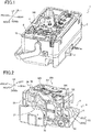
- the upper left side, the lower right side, the upper right side, the lower left side, the upper side, and the lower side in Fig. 1 are defined respectively as the front side, the rear side, the left side, the right side, the upper side, and the lower side of the printer 1 and the tape cassette 100.
- the printer 1 according to the present embodiment is capable of selectively performing printing on a tape 10 and printing on a tube, not illustrated.
- the printer 1 at least needs to be capable of performing printing on the tape 10.
- the following description is given only for a mechanism of the printer 1 which relates to printing on the tape 10.
- the printer 1 may use various types of the tape cartridge 100 such as a thermal type, a receptor type, and a laminate type.
- the tape cassette 100 is of the receptor type in the present embodiment.
- the printer 1 includes: a main body 2 shaped like a substantially rectangular parallelepiped box; and a cover, not illustrated, capable of closing an opening formed in an upper portion of the main body 2.
- a cartridge holder 4 is provided at a right portion of an upper surface of the main body 2.
- the cartridge holder 4 is a recess in which the tape cartridge 100 is removably mountable.
- An output opening 6 is formed in a right portion of a front surface of the main body 2. The tape 10 having been printed is discharged from the cartridge holder 4 to the outside of the printer 1 through the output opening 6.
- an internal unit 8 is provided at a right portion of the main body 2.
- the internal unit 8 includes a bottom plate 4A that constitutes a bottom surface of the cartridge holder 4.
- a head holder 20 is provided upright at a right portion of a substantially central portion of the cartridge holder 4 in the front and rear direction.
- a thermal head 22 including heating elements, not illustrated, is provided on a right surface of the head holder 20.
- the thermal head 22 performs printing on the tape 10 conveyed along a predetermined conveyance path by, e.g., a platen roller 32 which will be described below.
- a ribbon take-up shaft 25 is provided upright on the cartridge holder 4 at a position located to the left of the head holder 20.
- a conveying-roller drive shaft 24 is provided upright on the cartridge holder 4 at a position located in front of the head holder 20.
- the ribbon take-up shaft 25 is inserted and fitted in a ribbon take-up roller 104 which will be described below, and the conveying-roller drive shaft 24 is inserted and fitted in a conveying roller 102 which will be described below.
- a drive motor, not illustrated, as a stepping motor is provided in the main body 2 at a position located outside the cartridge holder 4.
- the ribbon take-up shaft 25, the conveying-roller drive shaft 24, and the platen roller 32 which will be described below are connected to a drive motor via a plurality of gears, not illustrated, and rotated by power generated by the drive motor.
- the ribbon take-up shaft 25 fitted in the ribbon take-up roller 104 rotates the ribbon take-up roller 104.
- the conveying-roller drive shaft 24 fitted in the conveying roller 102 rotates the conveying roller 102.
- the platen roller 32 conveys the tape 10 and an ink ribbon 118 as will be described below.
- the tape cassette 100 includes a cassette casing 101 having a substantially rectangular parallelepiped shape.
- the cassette casing 101 includes an upper first casing portion 101A and a lower second casing portion 101B.
- the casing portions 101A, 101B are fixed to each other as one unit.
- a roll storatge 120 provided in the cassette casing 101 stores: a tape roll 122 that is a roll of the tape 10; and a ribbon roll 124 that is a roll of the ink ribbon 118.
- the tape roll 122 is rotatably supported in a support hole 130 at a front left portion of the roll storatge 120.
- the ribbon roll 124 is rotatably supported in a support hole 132 at a rear right portion of the roll storatge 120.
- the ribbon take-up roller 104 is rotatably supported by a shaft between the tape roll 122 and the ribbon roll 124 in the cassette casing 101.
- the ribbon take-up roller 104 is rotated by the ribbon take-up shaft 25 to draw the ink ribbon 118 from the ribbon roll 124 and take up the used ink ribbon 118.
- the ink ribbon 118 has black ink, for example.
- the ink ribbon 118 has an ink layer and a substrate.
- the substrate is formed of resin such as polyethylene terephthalate (PET).
- PET polyethylene terephthalate
- the ink layer contains a color component and a binder component such as wax and/or resin.
- the color component contained in the ink layer is carbon, for example.
- the cassette casing 101 includes an arm 160 extending frontward from a rear right portion of the roll storatge 120.
- the arm 160 includes: a first arm 160A located near the first casing portion 101A; and a second arm 160B located near the second casing portion 101B.
- An unused tape 10 drawn from the tape roll 122 and an unused ink ribbon 118 drawn from the ribbon roll 124 are guided in the arm 160.
- the tape 10 is guided in the arm 160 in a state in which the widthwise direction of the tape 10 is parallel with the up and down direction, a fourth surface 12B of a printing sheet 12 (see Figs.
- the ink ribbon 118 is guided in the arm 160 at a position located to the left of the tape 10 in a state in which the widthwise direction of the tape 10 is parallel with the up and down direction. After guided frontward in the arm 160, the tape 10 and the ink ribbon 118 are arranged on one another in an opening 161 formed in the front end of the arm 160 and are discharged frontward from the arm 160.
- the conveying roller 102 is rotatably supported by a shaft in the cassette casing 101 at a position located in front of the arm 160.
- An output guide 140 is provided at a front right corner of the cassette casing 101.
- a pressing roller 34 which will be described below, is opposed to the conveying roller 102.
- the conveying roller 102 is cooperated with the pressing roller 34 to draw the tape 10 from the tape roll 122 and convey the printed tape 10 toward the output opening 6 via the output guide 140.
- the ink ribbon 118 is guided toward the ribbon take-up roller 104 at a position located upstream of the conveying roller 102 in the conveying direction.
- the first casing portion 101A includes a right wall 103 of the first arm 160A.
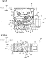
- the right wall 103 has a detection hole 150 extending through the right wall 103 and having a substantially rectangular shape.
- the detection hole 150 is formed at a position opposed to a path of movement of various kinds of labels (see Figs. 8-12 ), which will be described below, disposed on the tape 10 conveyed in the arm 160.
- the detection hole 150 is used for an optical sensor 56 (see Fig. 7 ), which will be described below, to optically detect the various kinds of labels which will be described below. A detailed configuration of this will be described below.
- the second casing portion 101B includes a right wall 105 of the second arm 160B which is located under the right wall 103 of the first arm 160A.
- the right wall 105 has: an indicator portion 158 indicating information relating to the tape 10; and an insertion hole 154 having a substantially rectangular shape.
- the indicator portion 158 defines the information relating to the tape 10, such as the width of the tape 10, in accordance with combinations of insertion holes 156 or surface portions 157 respectively corresponding to sensor protrusions 66 which will be described below.
- the insertion hole 154 is a hole into which a guide protrusion 58 (see Fig. 7 ) which will be described below is inserted.
- a pivotably supporting portion 38 having a three-sided rectangular shape extending in the front and rear direction is provided to the right of the head holder 20 in the cartridge holder 4.
- the pivotably supporting portion 38 supports holder arms 36A, 36B each extending in the front and rear direction, such that the holder arms 36A, 36B are interposed between opposed portions of the pivotably supporting portion 38.
- Each of the holder arms 36A, 36B is pivotable about an axis AX1 by a support shaft 40 extending in the up and down direction.
- the first holder arm 36A is disposed in a lower portion of an inner space of the pivotably supporting portion 38.
- the second holder arm 36B is disposed in an upper portion of the inner space of the pivotably supporting portion 38, that is, the second holder arm 36B is disposed above the first holder arm 36A.
- a roller holder 28 is supported by the holder arms 36A, 36B so as to be pivotable about the axis AX1 with the holder arms 36A, 36B.
- the platen roller 32 and the pressing roller 34 are rotatably provided on the roller holder 28.
- the platen roller 32 is opposed to the thermal head 22 such that a roller surface of the platen roller 32 is exposed leftward.
- the pressing roller 34 is opposed to the conveying-roller drive shaft 24 such that a roller surface of the pressing roller 34 is exposed leftward.
- a torsion spring is mounted on a lower end portion of the support shaft 40.
- the torsion spring resiliently urges the holder arms 36A, 36B and the roller holder 28 rightward (away from the thermal head 22) about the axis AX1.
- each of the holder arms 36A, 36B and the roller holder 28 is kept at a release position (illustrated in Fig. 5 ) by an urging force of the torsion spring.
- the platen roller 32 and the pressing roller 34 are separated respectively from the thermal head 22 and the conveying roller 102.
- each of the holder arms 36A, 36B and the roller holder 28 pivots rightward from the release position to a printing position (illustrated in Figs. 3 and 4 ).
- the platen roller 32 and the pressing roller 34 presses the tape 10 located on the conveyance path, respectively against the thermal head 22 and the conveying roller 102.
- the conveying roller 102 When the platen roller 32, the pressing roller 34, and the conveying-roller drive shaft 24 (the conveying roller 102) are rotated in the state in which the tape cassette 100 is mounted on the cartridge holder 4, and each of the holder arms 36A, 36B and the roller holder 28 is located at the printing position, the tape 10 contained in the tape cassette 100 is conveyed along the predetermined conveyance path.
- a release rod 70 and a release motor 71 are provided on the main body 2.
- the release rod 70 is disposed to the right of the holder arms 36A, 36B so as to extend in the front and rear direction.
- a left portion of the release rod 70 includes a first engaging portion 70A and a second engaging portion 70B.
- the first engaging portion 70A extends on a front right side of the second engaging portion 70B.
- the release motor 71 is mechanically coupled to the release rod 70 and driven to move the release rod 70 in the front and rear direction.
- a pressing portion 74 shaped like a roller is provided at a front end portion of the release rod 70.
- the release rod 70 is moved frontward by the release motor 71, the pressing portion 74 is also moved frontward and brought into contact with the roller holder 28. With this operation, each of the holder arms 36A, 36B and the roller holder 28 is rotated rightward about the axis AX1 and thereby moved from the release position to the printing position.
- the release rod 70 is moved rearward by the release motor 71, the pressing portion 74 is moved rearward and thereby separated from the roller holder 28. This separation causes each of the holder arms 36A, 36B and the roller holder 28 to be rotated leftward about the axis AX1 and thereby moved from the printing position to the release position.
- a sensor 29 is provided on a rear portion of the cartridge holder 4 at a substantially center of the cartridge holder 4 in the right and left direction.
- the sensor 29 optically detects a terminal-end mark, not illustrated, provided on the tape 10 of the tape cassette 100 mounted on the cartridge holder 4.
- the terminal-end mark will be described later.
- a sensor unit 50 movable with respect to the tape cassette 100 mounted on the cartridge holder 4 is provided to the left of the release rod 70 in the main body 2.
- the sensor unit 50 includes a mechanical sensor 54 and the optical sensor 56 as one unit.
- the sensor unit 50 is inserted in a space 37 (see Fig. 2 ) formed between the holder arms 36A, 36B.
- the space 37 is located upstream of the thermal head 22 in the conveying direction.
- the sensor unit 50 includes a circuit board 60 shaped like a plate and a unit body 51 shaped like a box.
- the circuit board 60 is located to the right of the unit body 51.
- the circuit board 60 is connected to a control circuit, not illustrated, of the printer 1 via a cable, not illustrated, connected to a connector, not illustrated, provided on the circuit board 60.
- the mechanical sensor 54 includes a plurality of the sensor protrusions 66 (five sensor protrusions 66 in this example) provided at a substantially quadrangle portion 53 of a left surface of the circuit board 60. Each of the sensor protrusions 66 protrudes through an opening formed in the unit body 51, to a position located to the left of a left surface of the unit body 51.
- the indicator portion 158 see Fig. 6
- the sensor protrusions 66 opposed to the insertion holes 156 see Fig.
- the control circuit, not illustrated, of the printer 1 detects information about the width of the tape 10 based on combination of ON and OFF of the sensor protrusions 66.
- the optical sensor 56 is provided on a substantially triangle portion 52 of the left surface of the circuit board 60.
- the optical sensor 56 is a reflective optical sensor capable of optically detecting an object through the opening formed in the unit body 51.
- the optical sensor 56 includes a light emitting element 56A and a light receiving element 56B arranged in the up and down direction.
- the light emitting element 56A is a light-emitting diode (LED) configured to emit near-infrared light (0.8 ⁇ m to 1.0 ⁇ m), for example.
- the light receiving element 56B is a photodiode having sensitivity to the near-infrared light, for example.
- the detection hole 150 formed in the arm 160 is opposed to the optical sensor 56.
- the control circuit, not illustrated, of the printer 1 is capable of detecting various kinds of information relating to the tape 10 based on a result of detection of the optical sensor 56, but the detail of which will be described later. It is noted that the optical sensor 56 may be of a transmission type.
- the guide protrusion 58 is provided at an upper rear portion of the substantially quadrangle portion 53 of the unit body 51.
- a cylindrical portion 62 (see Fig. 3 ) is provided at the substantially quadrangle portion 53 of the unit body 51 so as to extend to a position located to the right of a right surface of the circuit board 60, via the through hole formed in the circuit board 60.
- a coil spring 64 (see Fig. 3 ) is provided in the cylindrical portion 62. The coil spring 64 resiliently urges the sensor unit 50 leftward.
- a guide portion, not illustrated, extending downward is provided near a right end portion of the cylindrical portion 62. The guide portion of the cylindrical portion 62 is engaged with the first engaging portion 70A or the second engaging portion 70B (see Fig. 3 ) of the release rod 70. Leftward movement of the sensor unit 50 by the urging force of the coil spring 64 is inhibited by the engagement between the guide portion and the first engaging portion 70A or the second engaging portion 70B.
- the release rod 70 When the release rod 70 is moved frontward by the release motor 71, the guide portion of the cylindrical portion 62 is moved from the first engaging portion 70A to the second engaging portion 70B with leftward movement of the sensor unit 50.
- the sensor unit 50 When the guide portion of the cylindrical portion 62 is engaged with the second engaging portion 70B, the sensor unit 50 is kept at the detecting position (illustrated in Figs. 3 and 4 ).
- the sensor protrusions 66 of the mechanical sensor 54 are opposed to the indicator portion 158, the guide protrusion 58 is inserted in the insertion hole 154, and the optical sensor 56 is opposed to the detection hole 150.
- the release rod 70 When the release rod 70 is moved rearward by the release motor 71, the guide portion is moved from the second engaging portion 70B to the first engaging portion 70A with rightward movement of the sensor unit 50.
- the sensor unit 50 When the guide portion of the cylindrical portion 62 is engaged with the first engaging portion 70A, the sensor unit 50 is kept at the release position (illustrated in Fig. 5 ).
- the sensor protrusions 66 of the mechanical sensor 54 are separated from the indicator portion 158, the guide protrusion 58 is separated from the insertion hole 154, and the optical sensor 56 is separated from the detection hole 150.
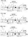
- a tape 10A illustrated in Fig. 8 is a first example of the tape 10.
- a tape 10B illustrated in Fig. 9 is a second example of the tape 10.
- a tape 10C illustrated in Fig. 10 is a third example of the tape 10.
- a tape 10D illustrated in Fig. 11 is a fourth example of the tape 10.
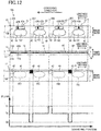
- a tape 10E illustrated in Fig. 12 is a fifth example of the tape 10.
- the tape 10 is shaped like a strip extending in its lengthwise direction and its widthwise direction. The lengthwise direction coincides with a direction in which the tape 10 of the tape roll 122 (see Fig.
- the widthwise direction coincides with a direction orthogonal to the lengthwise direction and corresponds to the widthwise direction of the tape 10.
- the direction of the tape 10 which is orthogonal to each of the lengthwise direction and the widthwise direction is a thickness direction.
- the tape 10 includes the separation sheet 11 and the printing sheet 12.
- the separation sheet 11 has opposite surfaces in the thickness direction, namely, the first surface 11A and a second surface 11B.
- the separation sheet 11 is release paper (such as glassine, high-quality paper, or kraft paper) covered with a release agent formed of a silicon-based material, for example.
- the separation sheet 11 may be formed of a material other than the release paper.
- the separation sheet 11 may be a release film formed of a resin film.
- the ground color of the separation sheet 11 is a color (gray) between white and black. Thus the color of each of the first surface 11A and the second surface 11B is gray corresponding to the ground color of the separation sheet 11.
- the printing sheet 12 has a printing layer 18 and an adhesive layer 19 stacked on each other in the thickness direction.
- the printing layer 18 has opposite surfaces in the thickness direction, namely, a third surface 12A and the fourth surface 12B.
- the printing layer 18 is a film formed of resin such as PET, PVC, PP, PE, PS, and ABS.
- the adhesive layer 19 is a transparent layer formed of adhesive and disposed on the third surface 12A.
- the adhesive layer 19 contains acrylic adhesive, for example.
- the ground color of the printing layer 18 is white.
- the color of each of the third surface 12A and the fourth surface 12B is white corresponding to the ground color of the printing layer 18.
- the printing sheet 12 is peelably stuck to the second surface 11B, with the adhesive layer 19 interposed therebetween.
- the thermal head 22 (see Fig. 4 ) forms an image on the fourth surface 12B by thermal transfer of the ink ribbon 118.
- the tape 10 is rolled in a state in which the printing sheet 12 is located on an inner circumferential side, and the separation sheet 11 is located on an outer circumferential side.
- the terminal-end mark having a grid pattern is printed on a trailing end portion of the first surface 11A in the conveying direction.
- the printer 1 uses the sensor 29 (see Fig. 4 ) to detect the terminal-end mark to determine that a remaining amount of the tape 10 of the tape roll 122 is small.
- the printer 1 cuts the printed tape 10 into the predetermined length to create a label piece.
- the user can peel the printing sheet 12 of the created label piece from the separation sheet 11 and stick the printing sheet 12 to an object such as a cable.
- the printer 1 according to the present embodiment may use the tape 10 of a die-cut label type and the tape 10 of a normal label type.
- Half cut is formed in the tape 10 of the die-cut label type to divide the printing sheet 12 into a label portion and a non-label portion. No half cut is formed in the printing sheet 12 of the tape 10 of the normal label type.
- the tape 10A is of the die-cut label type for creating the label piece having the fixed length.
- the printing sheet 12 has a plurality of half cuts 14 formed by half cut. In other words, each of the half cuts 14 extends through the printing sheet 12 but not through the separation sheet 11.
- Each of the half cuts 14 has a closed outline. Portions of the printing sheet 12 which are enclosed by the respective half cuts 14 serve as label portions 15. That is, the printing sheet 12 has the label portions 15 corresponding to the respective half cuts 14.
- the label portions 15 include labels 15A and labels 15B. Each of the labels 15A and each of the labels 15B are different in shape from each other. Each of the labels 15A has a rectangular shape elongated in the lengthwise direction of the tape 10A. Each of the labels 15B has a round shape. In the present example, the labels 15A and the labels 15B are arranged in the lengthwise direction at a central region of the tape 10A in the widthwise direction. The labels 15A, 15B are alternately arranged at predetermined intervals. A portion of the printing sheet 12 which is different from the label portions 15 is a non-label portion 16. In the present example, the tape 10A has the non-label portion 16 as a portion of the printing sheet 12 but may not have the non-label portion 16 such that a portion of the separation sheet 11 which corresponds to the non-label portion 16 is exposed.
- Label markers 42, 43 are provided on the first surface 11A of the separation sheet 11.
- Each of the label markers 42 is a white region printed with ink containing white pigment.
- the white pigment is well-known inorganic white pigment, examples of which include: sulfate and carbonate as alkaline-earth-metal compounds; silicas such as powdered silica and synthetic silicate; calcium silicate; alumina, alumina hydrate; titanium oxide; zinc oxide; talc; and clay.
- Each of the label markers 43 is a black region printed with ink containing black pigment.
- the label markers 42 and the label markers 43 having the same quadrangle shape are provided at one end portion (i.e., an upper end portion) of the first surface 11A in the widthwise direction.
- the label markers 42 and the label markers 43 are alternately arranged in the lengthwise direction at predetermined intervals.
- a plurality of regions on the first surface 11A, each of which is adjacent to at least one of the label markers 42, 43 in the lengthwise direction, are a plurality of ground-color markers 41.
- the ground-color markers 41 each having the ground color (gray) of the first surface 11A correspond to the respective label portions 15.
- the label markers 42 are provided corresponding to the respective labels 15A.
- Each of the label markers 42 is located downstream of a corresponding one of the labels 15A and upstream of a first downstream label in the conveying direction in which the tape 10A is conveyed.
- the first downstream label is one of the labels 15B which is located downstream of and adjacent to the corresponding one of the labels 15A in the conveying direction.
- an upstream end portion of each of the label markers 42 is located downstream of a downstream end portion of the corresponding one of the labels 15A in the conveying direction.
- a downstream end portion of each of the label markers 42 is located upstream of an upstream end portion of the corresponding first downstream label in the conveying direction.
- the position of the downstream end portion of each of the label markers 42 is the same as a cut position C of an upstream end portion of a label piece 202 which will be described below.
- the label markers 43 are provided corresponding to the respective labels 15B.
- Each of the label markers 43 is located downstream of a corresponding one of the labels 15B and upstream of a second downstream label in the conveying direction.
- the second downstream label is one of the labels 15A which is located downstream of and adjacent to the corresponding one of the labels 15B in the conveying direction.
- an upstream end portion of each of the label markers 43 is located downstream of a downstream end portion of the corresponding one of the labels 15B in the conveying direction.
- a downstream end portion of each of the label markers 43 is located upstream of an upstream end portion of the corresponding second downstream label in the conveying direction.
- the position of the downstream end portion of each of the label markers 43 is the same as a cut position C of an upstream end portion of a label piece 201 which will be described below.
- each of the ground-color markers 41, each of the label markers 42, and each of the label markers 43 are opposed to the detection hole 150 (see Fig. 6 ) in the thickness direction when the tape 10A is conveyed.
- Light L emitted from the optical sensor 56 (see Fig. 7 ) impinges on the label marker 42, the ground-color marker 41, the label markers 43, the ground-color marker 41, the label marker 42, the ground-color marker 41, the label markers 43, and so on in this order during conveyance of the tape 10A.
- each of the ground-color markers 41 i.e., the gray region
- the reflectivity TH is not particular reflectivity but is reflectivity of a particular width which has reflectivity close to the particular reflectivity.
- the light with the particular wavelength is the light L emitted from the light emitting element 56A of the optical sensor 56. It is noted that the particular wavelength may have a certain degree of range. For example, the particular wavelength is a wavelength range with sensitivity to light reception of the light receiving element 56B of the optical sensor 56.
- each of the label markers 42 is a white region brighter than the gray region, the reflectivity of the label markers 42 to the light with the particular wavelength is greater than the reflectivity TH. That is, the reflectivity of the label markers 42 to the light with the particular wavelength is greater than that of the ground-color markers 41 to the light with the particular wavelength.
- each of the label markers 43 is a black region darker than the gray region, the reflectivity of the label markers 43 to the light with the particular wavelength is less than the reflectivity TH. That is, the reflectivity of the label markers 43 to the light with the particular wavelength is less than that of the ground-color markers 41 to the light with the particular wavelength.
- the label markers 42 and the label markers 43 are the same as each other in position in the widthwise direction.
- the label markers 42 and the label markers 43 are the same as each other in position in the lengthwise direction.
- an upstream end portion of the white marker (the label marker 42) nearest to a downstream end of the tape roll 122 in the conveying direction is located downstream, in the conveying direction, of a downstream end portion of the black marker (the label marker 43) nearest to the downstream end of the tape roll 122 in the conveying direction.
- Fig. 6 illustrates an unused tape cassette 100 (e.g., at the point of sale) containing the tape 10A as the tape 10. In the unused tape cassette 100, as illustrated in Fig.
- the most-downstream label marker 42 in the conveying direction is opposed to the detection hole 150 (see Fig. 6 ) in the thickness direction and exposed to the outside of the cassette casing 101 through the detection hole 150.
- the printer 1 draws the tape 10A from the tape roll 122 contained in the tape cassette 100 mounted on the cartridge holder 4 and conveys the tape 10A.
- the control circuit, not illustrated, of the printer 1 prestores a particular intensity of the light L to be emitted.
- the optical sensor 56 emits the emitted light L of the particular intensity through the detection hole 150 to the first surface 11A of the tape 10A conveyed in the arm 160 and receives the light reflected from the first surface 11A.
- the printer 1 detects, as reflectivity, the intensity of the received reflected light.
- the printer 1 detects reflectivity T1 when the light L is emitted to the label marker 42, detects the reflectivity TH when the light L is emitted to the ground-color marker 41, and detects reflectivity T2 when the light L is emitted to the label marker 43 (see Fig. 8 ).
- the reflectivity T1 is greater than the reflectivity TH.
- the reflectivity T2 is less than the reflectivity TH.
- the reflectivity may be a ratio of the intensity of the reflected light to the intensity of the emitted light L.
- each of the reflectivity T1 and the reflectivity T2 may be a value determined in advance at a predetermined ratio with respect to the reflectivity TH as a reference.
- the control circuit, not illustrated, of the printer 1 stores label information relating to each of the labels 15A, in association with the reflectivity T1 and stores label information relating to each of the labels 15B, in association with the reflectivity T2.
- the label information relating to each of the labels 15A indicates the length of the label piece 201 including the label 15A, and the position, the shape, and the size of the label 15A in the label piece 201, for example.
- the label information relating to each of the labels 15B indicates the length of the label piece 202 including the label 15B, and the position, the shape, and the size of the label 15B in the label piece 202, for example.
- the printer 1 When the reflectivity T1 is detected, the printer 1 prints an image on the label 15A of the conveyed tape 10A based on the label information relating to the label 15A. The printer 1 cuts the conveyed tape 10A at the cut position C located upstream of the printed label 15A. The printer 1 thereby creates the label piece 201 having an appropriate length with the image printed at an appropriate position on the label 15A. Likewise, when the reflectivity T2 is detected, the printer 1 can, based on the label information relating to each of the labels 15B, create the label piece 202 having an appropriate length with an image printed at an appropriate position in the label 15B.
- the user only needs to visually check the first surface 11A of the created label piece to identify whether the created label piece is the label piece 201 or 202.
- the user need not visually check the fourth surface 12B to identify that the created label piece is the label piece 201 including the label 15A.
- the label marker 43 is provided on the first surface 11A, the user need not visually check the fourth surface 12B to identify that the created label piece is the label piece 202 including the label 15B.
- the tape 10B illustrated in Fig. 9 will be next described the tape 10B illustrated in Fig. 9 in detail. Since the tape 10B is of the normal label type for creating a label piece having a variable length, the half cuts 14 and the label portions 15 (see Fig. 8 ) are not provided on the tape 10B. It is noted that the tape 10B may be of the normal label type for creating the label piece having the fixed length. It is noted that the same reference numerals as used for the tape 10A (see Fig. 8 ) are used to designate the corresponding elements of the tape 10B, and an explanation of which is dispensed with.
- a plurality of remaining-amount markers 44 are provided on the first surface 11A of the separation sheet 11 so as to be arranged in the lengthwise direction at predetermined intervals.
- Each of the remaining-amount markers 44 is constituted by one white marker 44A and one black marker 44B.
- Each of the white markers 44A is a white region like the label markers 42 (see Fig. 8 ).
- Each of the black markers 44B is a black region like the label markers 43 (see Fig. 8 ).
- a portion of the first surface 11A which is different from the remaining-amount markers 44 is the ground-color markers 41.
- the white marker 44A has a rectangular shape extending across the tape 10B in the widthwise direction and extending in the lengthwise direction with a particular width.
- the black marker 44B has a rectangular shape extending across the tape 10B in the widthwise direction and extending in the lengthwise direction with a width less than that of the white marker 44A.
- the black marker 44B is stacked on a portion of the white marker 44A in the thickness direction. Specifically, since the white marker 44A is formed on the first surface 11A, the white marker 44A is in direct contact with the first surface 11A. Since the black marker 44B is formed on the white marker 44A, the black marker 44B is located on an opposite side of the white marker 44A from the first surface 11A in the thickness direction.
- one of the black markers 44B and two of the white markers 44A disposed on opposite sides of the black marker 44B in the lengthwise direction may be formed without no space therebetween (noted that this applies to remaining-amount markers 46, 47 which will be described below).
- Each of the remaining-amount markers 44 indicates a remaining amount of the tape 10B as an amount of a portion of the tape 10B which is located upstream of the remaining-amount marker 44 in the conveying direction in the tape roll 122 (see Fig. 4 ).
- the remaining-amount marker 44 indicates a remaining amount of the tape 10B based on the position of the black marker 44B relative to the white marker 44A.
- the remaining-amount marker 44 indicates a large remaining amount of the tape 10B when the position of the black marker 44B is close to a downstream end portion of the white marker 44A in the conveying direction.
- the remaining-amount marker 44 indicates a small remaining amount of the tape 10B when the position of the black marker 44B is close to an upstream end portion of the white marker 44A in the conveying direction.
- One of the remaining-amount markers 44 is selectively opposed to the detection hole 150 (see Fig. 6 ) in the thickness direction when the tape 10B is conveyed.
- the light L emitted from the optical sensor 56 (see Fig. 7 ) impinges on the remaining-amount marker 44 (the white marker 44A and the black marker 44B), the ground-color marker 41, the remaining-amount marker 44, the ground-color marker 41, and so on during conveyance of the tape 10B.
- the white marker 44A and the black marker 44B are the same as each other in position in the widthwise direction. A portion of the white marker 44A and the black marker 44B are different from each other in position in the lengthwise direction. There will be described one example of image printing and label creation using the tape 10B.
- the printer 1 conveys the tape 10B as in the manner described above.
- the optical sensor 56 emits the light L and receives the light reflected from the first surface 11A through the detection hole 150 (see Fig. 9 ).
- the control circuit, not illustrated, of the printer 1 stores a remaining amount of the tape 10B which is related to a conveyance distance for specifying the remaining amount.
- the conveyance distance for specifying the remaining amount is a distance conveyed by the tape 10B from the time point when detected reflectivity changes from the reflectivity TH to the reflectivity T1, to the time point when the detected reflectivity changes from the reflectivity T1 to the reflectivity T2.
- the detected reflectivity is reflectivity detected by the printer 1 based on the reflected light detected by the optical sensor 56 as described above.
- the detected reflectivity changes from the reflectivity TH to the reflectivity T1 at a first time point when a position to which the light L is emitted changes from the ground-color marker 41 to the white marker 44A.
- the detected reflectivity changes from the reflectivity T1 to the reflectivity T2 at a second time point when the position to which the light L is emitted changes from the white marker 44A to the black marker 44B.
- the printer 1 can identify the remaining amount of the tape 10B based on the distance conveyed by the tape 10B from the first time point to the second time point (i.e., the conveyance distance for specifying the remaining amount). For example, the printer 1 may make notification about the identified remaining amount of the tape 10B at the start or the end of printing on the tape 10B, for example. The printer 1 may make an alert in the case where the identified remaining amount of the tape 10B is less than or equal to a predetermined threshold value.
- the printer 1 creates a label piece 203 having a variable length by cutting the printed tape 10B at the cut position C related to a designated label size or a size of an image to be printed.
- the user only needs to visually check the first surface 11A of the created label piece 203 to identify the remaining amount of the tape 10B. That is, in the case where the remaining-amount marker 44 is provided on the first surface 11A, the user can identify the remaining amount of the tape 10B based on the position of the black marker 44B relative to the white marker 44A as described above.
- the tape 10C illustrated in Fig. 10 is of the die-cut label type for creating the label piece having the fixed length.
- the label portions 15 corresponding to the respective half cuts 14 are formed in the printing sheet 12 of the tape 10C.
- the label portions 15 are labels 15C each having a rectangular shape elongated in the lengthwise direction.
- the labels 15C are provided on a central region of the tape 10C in the widthwise direction so as to be arranged in the lengthwise direction at predetermined intervals. It is noted that the same reference numerals as used for the tape 10A are used to designate the corresponding elements of the tape 10C, and an explanation of which is dispensed with.
- the label markers 42 are provided on the first surface 11A of the separation sheet 11 so as to correspond to the respective labels 15C.
- Each of the label markers 42 is located downstream of a corresponding one of the labels 15C and upstream of a third downstream label in the conveying direction in which the tape 10C is conveyed.
- the third downstream label is one of the labels 15C which is located downstream of and adjacent to the corresponding one of the labels 15C in the conveying direction.
- an upstream end portion of each of the label markers 42 is located downstream of a downstream end portion of the corresponding one of the labels 15C in the conveying direction.
- each of the label markers 42 is located upstream of an upstream end portion of the corresponding third downstream label in the conveying direction.
- each of the label markers 42 extends in the lengthwise direction so as to extend over the cut position C located at an upstream end of a corresponding one of label pieces 204 which will be described below.
- a plurality of remaining-amount markers 45 are provided on the first surface 11A of the separation sheet 11.
- the remaining-amount markers 45 are provided corresponding to the respective labels 15C so as to be arranged in the lengthwise direction at predetermined intervals.
- the remaining-amount marker 45 is located upstream of the label marker 42 in the conveying direction with a small space therebetween.
- the label marker 42 is provided on but the remaining-amount marker 45 is not provided on the most upstream label 15C in the conveying direction (i.e., the trailing-end label 15C).
- Each of the remaining-amount markers 45 is constituted by at least one black marker 45A.
- the black markers 45A are arranged in the lengthwise direction at predetermined intervals.
- Each of the black markers 45A has a rectangular shape extending across the tape 10C in the widthwise direction and extending in the lengthwise direction with a particular width. That is, the black markers 45A are longer than the label markers 42 in the widthwise direction. At least a portion of each of the black markers 45A overlaps a corresponding one of the labels 15C in the thickness direction.
- Each of the remaining-amount markers 45 indicates a remaining amount of the tape 10C as an amount of a portion of the tape 10C which is located upstream of the remaining-amount markers 45 in the conveying direction in the tape roll 122 (see Fig. 4 ).
- Each of the remaining-amount markers 45 specifically, the number of the black markers 45A contained in the remaining-amount marker 45, indicates the remaining number of the labels 15C, i.e., the number of the labels 15C located upstream of the remaining-amount marker 45 in the conveying direction.
- the remaining-amount markers 45 are opposed to the detection hole 150 (see Fig. 6 ) in the thickness direction when the tape 10C is conveyed.
- the light L emitted from the optical sensor 56 see Fig. 7
- the remaining-amount marker 45 at least one black marker 45A
- the label markers 42 and a portion of each of at least one black marker 45A are the same as each other in position in the widthwise direction.
- the label markers 42 and all the black markers 45A are different from each other in position in the lengthwise direction.
- an upstream end portion of the most-downstream white marker (i.e., the most-downstream label marker 42) on the tape roll 122 in the conveying direction is provided downstream, in the conveying direction, of a downstream end portion of the most-downstream black marker (i.e., the most-downstream black marker 45A) on the tape roll 122 in the conveying direction.
- the most-downstream label marker 42 in the conveying direction is exposed to the outside of the cassette casing 101 through the detection hole 150 in the unused tape cassette 100 (e.g., at the point of sale) as described above.
- the detection hole 150 in the unused tape cassette 100 e.g., at the point of sale
- the printer 1 conveys the tape 10C as in the manner described above.
- the optical sensor 56 receives, through the detection hole 150, the light L reflected from the first surface 11A (see Fig. 10 ).
- the control circuit, not illustrated, of the printer 1 stores the remaining number of the labels 15C which is related to the number of detected marks.
- the number of detected marks is the number of detections of the reflectivity T2 in a period extending from the time point when the detected reflectivity changes from the reflectivity T1 to the reflectivity TH, to the time point when the detected reflectivity changes from the reflectivity TH to the reflectivity T1.
- the detected reflectivity changes from the reflectivity T1 to the reflectivity TH at a third time point when the position to which the light L is emitted changes from the label marker 42 to the ground-color marker 41.
- the detected reflectivity changes from the reflectivity TH to the reflectivity T1 at a fourth time point when the position to which the light L is emitted changes from the ground-color marker 41 to the label marker 42.
- the printer 1 detects the reflectivity T2 the number of times which is the same as the number of the black markers 45A contained in the remaining-amount marker 45.
- the printer 1 can identify the remaining number of the labels 15C based on the number of detections of the reflectivity T2 in the period from the third time point to the fourth time point (i.e., the number of detected marks). The printer 1 may alert or make notification about the remaining number of the labels 15C as described above.
- the printer 1 can create the label piece 204 having an appropriate length on which an image is formed at an appropriate position on the label 15C.
- the user only needs to visually check the first surface 11A of the created label piece 204 to identify the remaining number of the labels 15C. That is, the user can visually check the remaining-amount marker 45 on the first surface 11A to recognize the remaining number of the labels 15C based on the number of the black markers 45A.
- the tape 10D illustrated in Fig. 11 in detail.
- the tape 10D is of the die-cut label type for creating the label piece having the fixed length.
- the label portions 15 corresponding to the respective half cuts 14 are formed in the printing sheet 12.
- the label portions 15 are the labels 15C each having a rectangular shape elongated in the lengthwise direction.
- the label markers 42 corresponding to the respective labels 15C are provided on the first surface 11A of the separation sheet 11. It is noted that the same reference numerals as used for the tape 10C are used to designate the corresponding elements of the tape 10D, and an explanation of which is dispensed with.
- the remaining-amount markers 46 are provided on the tape 10D instead of the remaining-amount markers 45 (see Fig. 10 ).
- Each of the remaining-amount markers 46 is similar in configuration to each of the remaining-amount markers 44 (see Fig. 9 ) and is constituted by one white marker 46A and one black marker 46B.
- the length of each of the remaining-amount markers 46 in the widthwise direction is less than that of a corresponding one of the labels 15C in the widthwise direction.
- the length of each of the remaining-amount markers 46 in the lengthwise direction is less than that of the corresponding label 15C in the lengthwise direction. That is, the size of each of the remaining-amount markers 46 is less than that of the corresponding label 15C.
- Each of the remaining-amount markers 46 is disposed at a central portion of the corresponding label 15C in the lengthwise direction and the widthwise direction. Thus, the entire portion of each of the remaining-amount markers 46 overlaps the corresponding label 15C in the thickness direction.
- the position of the remaining-amount markers 46 in the widthwise direction is different from the position of the label markers 42 in the widthwise direction. That is, the remaining-amount markers 46 and the label markers 42 are different from each other in position in the widthwise direction. Specifically, lower ends of the label markers 42 are separated from upper ends of the respective remaining-amount markers 46 in the up and down direction in Fig. 11 .
- the light L emitted from the optical sensor 56 see Fig. 7 ) impinges on the label markers 42 but does not impinge on the remaining-amount markers 46.
- each of the remaining-amount markers 46 the white marker 46A and the black marker 46B are the same as each other in position in the widthwise direction. A portion of the white marker 46A and the black marker 46B are different from each other in position in the lengthwise direction.
- each of a plurality of the white markers 46A and each of a plurality of the black markers 46B are provided within a corresponding one of the labels 15C in the lengthwise direction.
- an upstream end portion of the most-downstream white marker (i.e., the most-downstream label marker 42) on the tape roll 122 in the conveying direction is provided downstream, in the conveying direction, of a downstream end portion of the most-downstream black marker (i.e., the most-downstream black marker 46B) on the tape roll 122 in the conveying direction.
- the most-downstream label marker 42 in the conveying direction is exposed to the outside of the cassette casing 101 through the detection hole 150.
- the printer 1 performs image printing and label creation using the tape 10D. Based on label information about the label 15C, the printer 1 can create a label piece 205 having an appropriate length on which an image is formed at an appropriate position on the label 15C. The user can visually check the first surface 11A of the created label piece 205 to recognize the remaining number of the labels 15C based on the position of the black marker 46B relative to the white marker 46A.
- the tape 10E illustrated in Fig. 12 is of the die-cut label type for creating the label piece having the fixed length.
- the label portions 15 corresponding to the respective half cuts 14 are formed in the printing sheet 12.
- the label markers 42, 43 corresponding to the respective label portions 15 are provided on the first surface 11A of the separation sheet 11. It is noted that the same reference numerals as used for the tape 10A are used to designate the corresponding elements of the tape 10E, and an explanation of which is dispensed with.
- the label portions 15 include labels 15D and labels 15E.
- Each of the labels 15D and each of the labels 15E are different in shape from each other.
- Each of the labels 15D has a rectangular shape elongated in the lengthwise direction of the tape 10E.
- Each of the labels 15E has an oval shape elongated in the lengthwise direction of the tape 10E.
- the labels 15D and the labels 15E are provided near the other end portion of the tape 10E in the widthwise direction (i.e., a lower end portion of the fourth surface 12B).
- the labels 15D and the labels 15E are alternately arranged in the lengthwise direction at predetermined intervals.
- the printing sheet 12 is constituted by a gray substrate like the separation sheet 11.
- the color of each of the third surface 12A and the fourth surface 12B is gray corresponding to the ground color of the printing sheet 12.
- the remaining-amount markers 47 are provided on the fourth surface 12B of the printing sheet 12.
- the remaining-amount markers 47 are provided corresponding to the respective labels 15D, 15E so as to be arranged in the lengthwise direction at predetermined intervals.
- Each of the remaining-amount markers 47 is similar in configuration to each of the remaining-amount markers 45 (see Fig. 11 ) and is constituted by one white marker 47A and one black marker 47B.
- a portion of the fourth surface 12B which is different from the remaining-amount markers 47 is a ground-color portion 48 having the ground color of the fourth surface 12B (i.e., gray).
- each of the remaining-amount markers 47 in the widthwise direction is less than that of a corresponding one of the labels 15D and the labels 15E in the widthwise direction.
- the length of each of the remaining-amount markers 47 in the lengthwise direction is less than the corresponding one of the labels 15D and the labels 15E in the lengthwise direction. That is, the size of each of the remaining-amount markers 47 is less than that of the corresponding one of the labels 15D and the labels 15E.
- Each of the remaining-amount markers 47 is disposed between (i) the corresponding one of the labels 15D and the labels 15E and (ii) one end portion of the tape 10E in the widthwise direction (i.e., an upper end portion of the fourth surface 12B). Thus, each of the remaining-amount markers 47 is located next to the corresponding one of the labels 15D and the labels 15E in the widthwise direction.
- the label markers 42, 43 are provided on the first surface 11A of the separation sheet 11.
- the label markers 42 are provided corresponding to the respective labels 15D.
- the label markers 43 are provided corresponding to the respective labels 15E.
- each of the remaining-amount markers 47 the white marker 47A and the black marker 47B are the same as each other in position in the widthwise direction. A portion of the white marker 47A and the black marker 47B are different from each other in position in the lengthwise direction.
- each of a plurality of the white markers 47A and each of a plurality of the black markers 47B are provided within the corresponding one of the labels 15D and the labels 15E in the lengthwise direction.
- the upstream end portion of the most-downstream white marker (i.e., the most-downstream label marker 42) on the tape roll 122 in the conveying direction is provided downstream, in the conveying direction, of a downstream end portion of the most-downstream black marker (i.e., the most-downstream black marker 47B) on the tape roll 122 in the conveying direction.
- the most-downstream label marker 42 in the conveying direction is exposed to the outside of the cassette casing 101 through the detection hole 150 in the unused tape cassette 100 (e.g., at the point of sale) as described above.
- the printer 1 performs image printing and label creation using the tape 10E. Based on label information about the label 15D which is stored in the control circuit, not illustrated, the printer 1 can create a label piece 206 having an appropriate length on which an image is formed at an appropriate position on the label 15D. Based on label information about the label 15E which is stored in the control circuit, not illustrated, the printer 1 can create a label piece 207 having an appropriate length on which an image is formed at an appropriate position on the label 15E.
- the user need not visually check the fourth surface 12B to identify that the created label piece is the label piece 206 including the label 15D.
- the label marker 43 is provided on the first surface 11A
- the user need not visually check the fourth surface 12B to identify that the created label piece is the label piece 207 including the label 15E.
- the user can visually check the fourth surface 12B of the created label pieces 206 or 207 to recognize the remaining number of the labels 15D, 15E based on the position of the black marker 47B relative to the white marker 47A.
- the tape 10 has a strip shape extending in the lengthwise direction and the widthwise direction orthogonal to the lengthwise direction.
- the tape 10 has a subject surface (i.e., a gray one of the first surface 11A and the fourth surface 12B) located on the tape 10 and exposed in the thickness direction orthogonal to each of the lengthwise direction and the widthwise direction.
- a first marker (corresponding to the label markers 42 and the white markers 44A, 46A, 47A) is provided on the subject surface and is greater than the subject surface in reflectivity to the light with the particular wavelength.
- a second marker (corresponding to the label markers 43 and the black markers 44B, 45A, 46B, 47B) is provided on the subject surface and is less than the subject surface in the reflectivity. At least a portion of the first marker and at least a portion of the second marker are the same as each other in position in the widthwise direction. At least a portion of one of the first marker and the second marker and the other of the first marker and the second marker are different from each other in position in the lengthwise direction.
- the subject surface of the tape 10 in the case where two markers different from each other in reflectivity are provided on the subject surface of the tape 10, for example, it is assumed that two markers (e.g., a gray marker and a black marker) different from each other in reflectivity and less than the subject surface in reflectivity are provided.
- the subject surface is required to be white or a color close to white in order to set a difference in brightness between the ground color of the subject surface and each marker, to a sufficiently large value.
- the substrate of the tape 10 is limited to a substrate that satisfies the requirement.
- the first marker greater than the subject surface in reflectivity and the second marker less than the subject surface in reflectivity are provided.
- the reflectivity of the substrate of the tape 10 needs to be a value between the reflectivity of the first marker and the reflectivity of the second marker. Accordingly, when compared with the conventional tape, the tape 10 has improved flexibility of the substrate usable for forming the markers.
- On the tape 10, at least a portion of the first marker and at least a portion of the second marker are spaced apart from each other and arranged on the same straight line extending in the lengthwise direction. This configuration makes it easy for the user to visually check the first marker and the second marker and for the printer 1 to optically detect the first marker and the second marker.
- the tape 10 (the tapes 10C-10E) has the separation sheet 11 (as one example of a first sheet) and the printing sheet 12 (as one example of a second sheet).
- the printing sheet 12 has the printing layer 18 and the adhesive layer 19 provided on the printing layer 18, and the printing sheet 12 is peelably stuck to the separation sheet 11 with the adhesive layer 19 interposed therebetween.
- the printing sheet 12 includes a plurality of die-cut labels (i.e., the labels 15C-15E) arranged in the lengthwise direction.
- the subject surface is provided on at least one of the separation sheet 11 and the printing sheet 12.
- a plurality of the markers i.e., the white markers 46A or the white markers 47A, and the black markers 45A, the black markers 46B, or the black markers 47B
- At least a portion of each of the markers is provided, in the lengthwise direction, within an area on which a corresponding one of the die-cut labels is formed.
- each of the markers and a corresponding one of the die-cut labels are arranged on the same straight line extending in the widthwise direction.
- This configuration makes it easy for the user to identify the marker by visually checking it with reference to the die-cut label.
- the printer 1 can detect the marker near the die-cut label.
- the markers include the first markers (the white markers 46A or the white markers 47A) and the second markers (the black markers 46B or the black markers 47B).
- Each of the first markers is provided, in the lengthwise direction, within an area on which a corresponding one of the die-cut labels (the labels 15C-15E) is formed.
- Each of the second markers is provided, in the lengthwise direction, within an area on which a corresponding one of the die-cut labels (the labels 15C-15E) is formed.
- each of the first markers and the second markers and a corresponding one of the die-cut labels are arranged on the same straight line extending in the widthwise direction.
- This configuration makes it easy for the user to identify the first marker and the second marker by visually checking them with reference to the die-cut label.
- the printer 1 can detect each of the first markers and the second markers near the corresponding die-cut label.
- An upstream end portion of the most-downstream first marker (the most-downstream label marker 42) on the tape roll 122 in the conveying direction is provided downstream, in the conveying direction, of a downstream end portion of the most-downstream second marker (the most-downstream label markers 43 or the most-downstream black marker 45A, 46B, or 47B) on the tape roll 122 in the conveying direction.
- the optical sensor 56 detects the first marker before detecting the second marker.
- the printer 1 can perform calibration of the optical sensor 56 (e.g., setting of an upper limit value of light sensitivity) with reference to the first marker (i.e., the brightest marker) greater than the second marker in reflectivity.
- the cassette casing 101 has the detection hole 150 through which a portion of the tape 10 contained in the cassette casing 101 is exposed to the outside of the cassette casing 101. At least a portion of the first marker (the label markers 42) is opposed to the detection hole 150 in the thickness direction.
- This configuration enables the printer 1 to detect the first marker through the detection hole 150. The user can visually check the first marker through the detection hole 150.
- the optical sensor 56 is opposed to the first marker through the detection hole 150.
- the optical sensor 56 detects the brightest first marker, whereby the printer 1 can perform calibration of the optical sensor 56 before printing.
- the tape 10 is not limited to the tape for label creation and may be a tape constituted by a single-layer substrate without an adhesive layer (e.g., a single-layer tape for thermal printing).
- the printer 1 may use the sensor 29 (see Fig. 4 ) to detect the first markers and the second markers formed on the first surface 11A of the separation sheet 11.
- the printer 1 may include an optical sensor capable of optically detecting the first markers and the second markers formed on the fourth surface 12B of the printing sheet 12 (e.g., the remaining-amount markers 47 illustrated in Fig. 12 ).
- the printer 1 may include an optical sensor capable of optically detecting markers not detected by the optical sensor 56 (e.g., the remaining-amount markers 46 in Fig. 11 and the remaining-amount markers 47 in Fig. 12 ).
- the first marker is not limited to the white marker.
- the first marker only needs to be greater than the subject surface in reflectivity to the light with the particular wavelength.
- the first marker may be formed with a metal leaf, such as a leaf of aluminum, stuck thereto to make the first marker greater than white in reflectivity to the light with the particular wavelength.
- the second marker is not limited to the black marker.
- the second marker only needs to be less than the subject surface in reflectivity to the light with the particular wavelength.
- the particular wavelength is not limited to the wavelength of the light L emitted from the optical sensor 56 and may be any of other wavelengths.
- a color (i.e., reflectivity) appropriate for the particular wavelength may be used for the color of each of the subject surface, the first marker, and the second marker.
- first markers and the second markers may be changed in position, size, shape, the number, and so on without departing from the spirit and scope of the disclosure.
- at least one of each first marker and each second marker may be provided on a portion of the second surface 11B of the separation sheet 11 which is opposed to the non-label portion 16 (i.e., a portion of the second surface 11B which is not opposed to the label portion 15).
- each of the tapes 10F-10H is of the die-cut label type for creating the label piece having the fixed length.
- Each of the tapes 10F-10H is configured such that the label portions 15 corresponding to the respective half cuts 14 are formed in the printing sheet 12. It is noted that the same reference numerals as used for the tape 10D are used to designate the corresponding elements of the tapes 10F-10H, and an explanation of which is dispensed with.
- Each of the label portions 15 includes the label 15C and a label 15F different in shape from each other.
- Each of the labels 15F has an oval shape in the lengthwise direction of the tape 10F.
- the labels 15C and the labels 15F are provided on a central region of the tape 10F in the widthwise direction and alternately arranged in the lengthwise direction at predetermined intervals.
- the label markers 42, 43 are provided on an upper end portion of the first surface 11A of the separation sheet 11 so as to be arranged in the lengthwise direction. In the present example, the label markers 42 are provided corresponding to the respective labels 15C.
- each of the label markers 42 is located, in the lengthwise direction, between opposite end portions of a corresponding one of the labels 15C in the lengthwise direction.
- the label markers 43 are provided corresponding to the respective labels 15F.
- the entire portion of each of the label markers 43 is located, in the lengthwise direction, between opposite end portions of a corresponding one of the labels 15F in the lengthwise direction.
- the remaining-amount markers 46 are arranged in the lengthwise direction at the upper end portion of the first surface 11A.
- Each of the remaining-amount markers 46 is located upstream of a corresponding one of the label markers 42 and the label markers 43 in the conveying direction. Since the label markers 42, the label markers 43, and the remaining-amount markers 46 are different from each other in position in the lengthwise direction, these markers are not arranged in the widthwise direction.
- the entire portion of each of the remaining-amount markers 46 is located, in the lengthwise direction, between opposite end portions of a corresponding one of the labels 15C and the labels 15F in the lengthwise direction.
- the printer 1 configured to perform printing using the tape 10F detects the label marker 42 and creates a label piece 208 based on label information about the label 15C. Also, the printer 1 detects the label marker 43 and creates a label piece 209 based on label information about the label 15F. The printer 1 can identify the remaining number of the labels 15C, 15F based on a result of detection of the remaining-amount marker 46. The user can recognize whether the created label piece is the label piece 208 or 209, based on any of the label markers 42, 43 located on the first surface 11A of the label piece. The user can visually check the remaining-amount marker 46 to recognize the remaining number of the labels 15C, 15F.
- the tape 10G is different from the tape 10F (see Fig. 13A ) only in that the entire portion of each of the remaining-amount markers 46 overlaps a corresponding one of the labels 15C, 15F in the thickness direction. It is noted that, since the label markers 42, the label markers 43, and the remaining-amount markers 46 are different from each other in position in the lengthwise direction, these markers are not arranged in the widthwise direction.
- the light L emitted from the optical sensor 56 see Fig. 7
- the printer 1 configured to perform printing using the tape 10G can create the label pieces 208, 209. This configuration enables the user to recognize whether the created label piece is the label piece 208 or 209 and to recognize the remaining number of the labels 15C, 15F.
- the tape 10H is different from the tape 10G (see Fig. 13B ) in that the entire portion of each of the remaining-amount markers 46 overlaps a corresponding one of the labels 15C, 15F in the thickness direction and that the entire portion of each of the label markers 42, 43 overlaps a corresponding one of the labels 15C, 15F in the thickness direction. Since the label markers 42, the label markers 43, and the remaining-amount markers 46 are different from each other in position in the lengthwise direction, these markers are not arranged in the widthwise direction. In the present example, when the tape 10H is conveyed, the light L emitted from the optical sensor 56 (see Fig.
- the printing sheet 12 includes the die-cut labels (the labels 15C, 15F) arranged in the lengthwise direction.
- the first markers (the label markers 42 and the white marker 46A) and the second markers (the label markers 43 and the black markers 46B) are provided on the subject surface (the first surface 11A).
- Each of the first markers includes a first separation marker (the label marker 42) and a first stacked marker (the white marker 46A).
- the first separation marker is one of the first markers, and the entire first separation marker is separated from the second markers.
- the first stacked marker is another of the first markers, and at least a portion of the first stacked marker overlaps at least a portion of the second markers in the thickness direction.
- Each of the second markers includes a second separation marker (the label markers 43) and a second stacked marker (the black marker 46B).
- the second separation marker is one of the second markers, and the entire second separation marker is separated from the first markers.
- the second stacked marker is another of the second markers, and at least a portion of the second stacked marker overlaps at least a portion of the first markers in the thickness direction. At least a portion of each of the first separation marker, the first stacked marker, the second separation marker, and the second stacked marker is provided, in the lengthwise direction, within an area on which a corresponding one of the die-cut labels (i.e., the label 15C or the label 15F) is formed.
- each of the first separation marker, the second separation marker, the first stacked marker, and the second stacked marker, and a corresponding one of the die-cut labels are arranged on the same straight line extending in the widthwise direction.
- This configuration makes it easy for the user to identify the first separation marker, the second separation marker, the first stacked marker, and the second stacked marker by visually checking them with reference to the die-cut label.
- the printer 1 can detect each of the first separation markers, the second separation markers, the first stacked markers, and the second stacked markers near the corresponding die-cut label.
Landscapes
- Engineering & Computer Science (AREA)
- Physics & Mathematics (AREA)
- General Engineering & Computer Science (AREA)
- General Physics & Mathematics (AREA)
- Theoretical Computer Science (AREA)
- Mechanical Engineering (AREA)
- Mathematical Physics (AREA)
- Printers Characterized By Their Purpose (AREA)
- Impression-Transfer Materials And Handling Thereof (AREA)
Abstract
Description
- The following disclosure relates to a tape and a tape cassette for printing of a character.
- There is conventionally known a technique of providing a marker on a tape for printing of a character. The marker is an indicator indicating a predetermined position, for example. For example, Patent Document 1 (Japanese Patent Application Publication No.
2002-361959 - The above-described ticket printer discriminates between the ticket identification mark and the near-end identification mark based on a rate of decrease of the reflected light with respect to the roll sheet. In this case, in order to accurately discriminate the marks, the reflectivity of the roll sheet is required to be sufficiently higher than the reflectivity of each mark, in other words, a difference in brightness between the ground color of the roll sheet and the mark to be detected is required to be sufficiently large. Since a color and a material of a substrate for formation of each mark need to be those satisfying the above-described requirement, there is a possibility that substrates usable for formation of the marks are limited, unfortunately.
- Accordingly, an aspect of the disclosure relates to a tape and a tape cassette having improved flexibility of a substrate usable for forming markers.
- In one aspect of the disclosure, a tape has a strip shape extending in a lengthwise direction and a widthwise direction orthogonal to the lengthwise direction and includes: a subject surface located on the tape and exposed in a thickness direction orthogonal to each of the lengthwise direction and the widthwise direction; a first marker provided on the subject surface and being greater than the subject surface in reflectivity to light with a particular wavelength; and a second marker provided on the subject surface and being less than the subject surface in the reflectivity. At least a portion of the first marker and at least a portion of the second marker are identical to each other in position in the widthwise direction. At least a portion of one of the first marker and the second marker and at least a portion of another of the first marker and the second marker are different from each other in position in the lengthwise direction.
- In another aspect of the disclosure, a tape cassette includes: a tape roll that is a roll of a tape having a strip shape extending in a lengthwise direction and a widthwise direction orthogonal to the lengthwise direction, the tape including (i) a subject surface located on the tape and exposed in a thickness direction orthogonal to each of the lengthwise direction and the widthwise direction; (ii) a first marker provided on the subject surface and being greater than the subject surface in reflectivity to light with a particular wavelength; and (iii) a second marker provided on the subject surface and being less than the subject surface in the reflectivity, wherein at least a portion of the first marker and at least a portion of the second marker are identical to each other in position in the widthwise direction, and wherein at least a portion of one of the first marker and the second marker and at least a portion of another of the first marker and the second marker are different from each other in position in the lengthwise direction; and a cassette casing which accommodates the tape roll and in which the tape drawn from the tape roll is conveyed along a particular direction. The first marker nearest to a downstream end portion of the tape roll in the particular direction is provided downstream, in the particular direction, of the second marker nearest to the downstream end portion of the tape roll in the particular direction.
- According to the configurations as described above, the tape has improved flexibility of a substrate usable for forming markers.
- The tape further includes: a first sheet; and a second sheet peelably stuck to the first sheet, with a printing layer and an adhesive layer interposed between the first sheet and the second sheet. The second sheet includes a plurality of die-cut labels arranged in the lengthwise direction. The subject surface is provided on at least one of the first sheet and the second sheet. A plurality of markers at least include: a plurality of first markers each as the first marker; or a plurality of second markers each as the second marker are provided on the subject surface. At least a portion of each of the plurality of markers is located, in the lengthwise direction, within an area on which a corresponding one of the plurality of die-cut labels is formed.
- In the tape, the plurality of markers include the plurality of first markers and the plurality of second markers. The plurality of die-cut labels include: a plurality of first die-cut labels corresponding to the plurality of first markers; and a plurality of second die-cut labels corresponding to the plurality of second markers. Each of the plurality of first markers is located, in the lengthwise direction, within an area on which a corresponding one of the plurality of first die-cut labels is formed. Each of the plurality of second markers is located, in the lengthwise direction, within an area on which a corresponding one of the plurality of second die-cut labels is formed.
- In the tape, one of the first marker and the second marker is formed directly on the subject surface. At least a portion of another of the first marker and the second marker is located on an opposite side of at least a portion of the one of the first marker and the second marker from the subject surface in the thickness direction.
- In the tape, the second sheet includes a plurality of die-cut labels arranged along the lengthwise direction. A plurality of first markers each as the first marker and a plurality of second markers each as the second marker are provided on the subject surface. The plurality of first markers include: a first separation marker that is one of the plurality of first markers, an entirety of the first separation marker being spaced apart from the plurality of second markers; and a first stacked marker that is one of the plurality of first markers and that is different from the first separation marker, at least a portion of the first stacked marker being stacked on at least a portion of the plurality of second markers in the thickness direction. The plurality of second markers include: a second separation marker that is one of the plurality of second markers, an entirety of the second separation marker being spaced apart from the plurality of first markers; and a second stacked marker that is one of the plurality of second markers and that is different from the second separation marker, at least a portion of the second stacked marker being stacked on at least a portion of the plurality of first markers in the thickness direction. At least a portion of each of the first separation marker, the first stacked marker, the second separation marker, and the second stacked marker is located, in the lengthwise direction, within an area on which a corresponding one of the plurality of die-cut labels is formed.
- In the tape, the first marker is greater than white in the reflectivity.
- In the tape, the first marker is formed of ink containing a white pigment.
- In the tape cassette, the cassette casing includes an opening through which a portion of the tape located in the cassette casing is exposed to an outside of the cassette casing. At least a portion of the first marker is opposed to the opening in the thickness direction.
- The objects, features, advantages, and technical and industrial significance of the present disclosure will be better understood by reading the following detailed description of the embodiments, when considered in connection with the accompanying drawings, in which:
-
Fig. 1 is a perspective view illustrating an external appearance of a printer 1, with a cover omitted; -
Fig. 2 is a perspective view of aninternal unit 8; -
Fig. 3 is a plan view of theinternal unit 8; -
Fig. 4 is a cross-sectional view of theinternal unit 8; -
Fig. 5 is a plan view of theinternal unit 8; -
Fig. 6 is a right side view of atape cassette 100; -
Fig. 7 is a plan view of asensor unit 50 and components around thesensor unit 50; -
Fig. 8 is a view for explaining atape 10A; -
Fig. 9 is a view for explaining atape 10B; -
Fig. 10 is a view for explaining a tape 10C; -
Fig. 11 is a view for explaining atape 10D; -
Fig. 12 is a view for explaining atape 10E; and -
Figs. 13A through 13C are views for explainingtapes 10F-10H, respectively. - Hereinafter, there will be described one embodiment by reference to the drawings. The drawings are for explanation of technical features employable in the present disclosure. It is to be understood that the configuration illustrated in the drawings does not limit the present disclosure and is only one example.
- There will be described a printer 1 and a
tape cassette 100 according to the present embodiment with reference toFigs. 1-7 . The upper left side, the lower right side, the upper right side, the lower left side, the upper side, and the lower side inFig. 1 are defined respectively as the front side, the rear side, the left side, the right side, the upper side, and the lower side of the printer 1 and thetape cassette 100. As illustrated inFigs. 1-5 , the printer 1 according to the present embodiment is capable of selectively performing printing on atape 10 and printing on a tube, not illustrated. The printer 1 at least needs to be capable of performing printing on thetape 10. The following description is given only for a mechanism of the printer 1 which relates to printing on thetape 10. The printer 1 may use various types of thetape cartridge 100 such as a thermal type, a receptor type, and a laminate type. Thetape cassette 100 is of the receptor type in the present embodiment. - As illustrated in
Fig. 1 , the printer 1 includes: amain body 2 shaped like a substantially rectangular parallelepiped box; and a cover, not illustrated, capable of closing an opening formed in an upper portion of themain body 2. Acartridge holder 4 is provided at a right portion of an upper surface of themain body 2. Thecartridge holder 4 is a recess in which thetape cartridge 100 is removably mountable. Anoutput opening 6 is formed in a right portion of a front surface of themain body 2. Thetape 10 having been printed is discharged from thecartridge holder 4 to the outside of the printer 1 through theoutput opening 6. - As illustrated in
Figs. 2-4 , aninternal unit 8 is provided at a right portion of themain body 2. Theinternal unit 8 includes abottom plate 4A that constitutes a bottom surface of thecartridge holder 4. Ahead holder 20 is provided upright at a right portion of a substantially central portion of thecartridge holder 4 in the front and rear direction. Athermal head 22 including heating elements, not illustrated, is provided on a right surface of thehead holder 20. Thethermal head 22 performs printing on thetape 10 conveyed along a predetermined conveyance path by, e.g., aplaten roller 32 which will be described below. A ribbon take-upshaft 25 is provided upright on thecartridge holder 4 at a position located to the left of thehead holder 20. A conveying-roller drive shaft 24 is provided upright on thecartridge holder 4 at a position located in front of thehead holder 20. When thetape cassette 100 is mounted on thecartridge holder 4, the ribbon take-upshaft 25 is inserted and fitted in a ribbon take-uproller 104 which will be described below, and the conveying-roller drive shaft 24 is inserted and fitted in a conveyingroller 102 which will be described below. - A drive motor, not illustrated, as a stepping motor is provided in the
main body 2 at a position located outside thecartridge holder 4. The ribbon take-upshaft 25, the conveying-roller drive shaft 24, and theplaten roller 32 which will be described below are connected to a drive motor via a plurality of gears, not illustrated, and rotated by power generated by the drive motor. As a result, the ribbon take-upshaft 25 fitted in the ribbon take-uproller 104 rotates the ribbon take-uproller 104. The conveying-roller drive shaft 24 fitted in the conveyingroller 102 rotates the conveyingroller 102. Theplaten roller 32 conveys thetape 10 and anink ribbon 118 as will be described below. - As illustrated in
Figs. 2 and4 , thetape cassette 100 according to the present embodiment includes acassette casing 101 having a substantially rectangular parallelepiped shape. Thecassette casing 101 includes an upperfirst casing portion 101A and a lowersecond casing portion 101B. Thecasing portions roll storatge 120 provided in thecassette casing 101 stores: atape roll 122 that is a roll of thetape 10; and aribbon roll 124 that is a roll of theink ribbon 118. Thetape roll 122 is rotatably supported in asupport hole 130 at a front left portion of theroll storatge 120. Theribbon roll 124 is rotatably supported in asupport hole 132 at a rear right portion of theroll storatge 120. The ribbon take-uproller 104 is rotatably supported by a shaft between thetape roll 122 and theribbon roll 124 in thecassette casing 101. The ribbon take-uproller 104 is rotated by the ribbon take-upshaft 25 to draw theink ribbon 118 from theribbon roll 124 and take up the usedink ribbon 118. Theink ribbon 118 has black ink, for example. Specifically, theink ribbon 118 has an ink layer and a substrate. The substrate is formed of resin such as polyethylene terephthalate (PET). The ink layer contains a color component and a binder component such as wax and/or resin. In the case where theink ribbon 118 has black ink, the color component contained in the ink layer is carbon, for example. - As illustrated in
Figs. 3-6 , thecassette casing 101 includes anarm 160 extending frontward from a rear right portion of theroll storatge 120. Thearm 160 includes: afirst arm 160A located near thefirst casing portion 101A; and asecond arm 160B located near thesecond casing portion 101B. Anunused tape 10 drawn from thetape roll 122 and anunused ink ribbon 118 drawn from theribbon roll 124 are guided in thearm 160. Thetape 10 is guided in thearm 160 in a state in which the widthwise direction of thetape 10 is parallel with the up and down direction, afourth surface 12B of a printing sheet 12 (seeFigs. 8-12 ) which will be described below faces leftward, and afirst surface 11A of a separation sheet 11 (seeFigs. 8-12 ) which will be described below faces rightward. Theink ribbon 118 is guided in thearm 160 at a position located to the left of thetape 10 in a state in which the widthwise direction of thetape 10 is parallel with the up and down direction. After guided frontward in thearm 160, thetape 10 and theink ribbon 118 are arranged on one another in anopening 161 formed in the front end of thearm 160 and are discharged frontward from thearm 160. - The conveying
roller 102 is rotatably supported by a shaft in thecassette casing 101 at a position located in front of thearm 160. Anoutput guide 140 is provided at a front right corner of thecassette casing 101. Apressing roller 34, which will be described below, is opposed to the conveyingroller 102. When rotated by the conveying-roller drive shaft 24, the conveyingroller 102 is cooperated with thepressing roller 34 to draw thetape 10 from thetape roll 122 and convey the printedtape 10 toward theoutput opening 6 via theoutput guide 140. It is noted that theink ribbon 118 is guided toward the ribbon take-uproller 104 at a position located upstream of the conveyingroller 102 in the conveying direction. - As illustrated in
Fig. 6 , thefirst casing portion 101A includes aright wall 103 of thefirst arm 160A. Theright wall 103 has adetection hole 150 extending through theright wall 103 and having a substantially rectangular shape. Thedetection hole 150 is formed at a position opposed to a path of movement of various kinds of labels (seeFigs. 8-12 ), which will be described below, disposed on thetape 10 conveyed in thearm 160. Thedetection hole 150 is used for an optical sensor 56 (seeFig. 7 ), which will be described below, to optically detect the various kinds of labels which will be described below. A detailed configuration of this will be described below. - The
second casing portion 101B includes a right wall 105 of thesecond arm 160B which is located under theright wall 103 of thefirst arm 160A. The right wall 105 has: anindicator portion 158 indicating information relating to thetape 10; and aninsertion hole 154 having a substantially rectangular shape. Theindicator portion 158 defines the information relating to thetape 10, such as the width of thetape 10, in accordance with combinations ofinsertion holes 156 orsurface portions 157 respectively corresponding tosensor protrusions 66 which will be described below. Theinsertion hole 154 is a hole into which a guide protrusion 58 (seeFig. 7 ) which will be described below is inserted. - As illustrated in
Figs. 2-5 , apivotably supporting portion 38 having a three-sided rectangular shape extending in the front and rear direction is provided to the right of thehead holder 20 in thecartridge holder 4. Thepivotably supporting portion 38supports holder arms holder arms pivotably supporting portion 38. Each of theholder arms support shaft 40 extending in the up and down direction. Thefirst holder arm 36A is disposed in a lower portion of an inner space of thepivotably supporting portion 38. Thesecond holder arm 36B is disposed in an upper portion of the inner space of thepivotably supporting portion 38, that is, thesecond holder arm 36B is disposed above thefirst holder arm 36A. - A
roller holder 28 is supported by theholder arms holder arms platen roller 32 and thepressing roller 34 are rotatably provided on theroller holder 28. Theplaten roller 32 is opposed to thethermal head 22 such that a roller surface of theplaten roller 32 is exposed leftward. Thepressing roller 34 is opposed to the conveying-roller drive shaft 24 such that a roller surface of thepressing roller 34 is exposed leftward. - A torsion spring, not illustrated, is mounted on a lower end portion of the
support shaft 40. The torsion spring resiliently urges theholder arms roller holder 28 rightward (away from the thermal head 22) about the axis AX1. In a state in which each of theholder arms roller holder 28 is not pressed leftward (toward the thermal head 22), each of theholder arms roller holder 28 is kept at a release position (illustrated inFig. 5 ) by an urging force of the torsion spring. In the case where each of theholder arms roller holder 28 is located at the release position, theplaten roller 32 and thepressing roller 34 are separated respectively from thethermal head 22 and the conveyingroller 102. - When pressed rightward against the urging force of the torsion spring, each of the
holder arms roller holder 28 pivots rightward from the release position to a printing position (illustrated inFigs. 3 and 4 ). In the case where each of theholder arms roller holder 28 is located at the printing position, theplaten roller 32 and thepressing roller 34 presses thetape 10 located on the conveyance path, respectively against thethermal head 22 and the conveyingroller 102. When theplaten roller 32, the pressingroller 34, and the conveying-roller drive shaft 24 (the conveying roller 102) are rotated in the state in which thetape cassette 100 is mounted on thecartridge holder 4, and each of theholder arms roller holder 28 is located at the printing position, thetape 10 contained in thetape cassette 100 is conveyed along the predetermined conveyance path. - As illustrated in
Figs. 3-5 , arelease rod 70 and arelease motor 71 are provided on themain body 2. Therelease rod 70 is disposed to the right of theholder arms release rod 70 includes a firstengaging portion 70A and a secondengaging portion 70B. The firstengaging portion 70A extends on a front right side of the secondengaging portion 70B. Therelease motor 71 is mechanically coupled to therelease rod 70 and driven to move therelease rod 70 in the front and rear direction. - A
pressing portion 74 shaped like a roller is provided at a front end portion of therelease rod 70. When therelease rod 70 is moved frontward by therelease motor 71, thepressing portion 74 is also moved frontward and brought into contact with theroller holder 28. With this operation, each of theholder arms roller holder 28 is rotated rightward about the axis AX1 and thereby moved from the release position to the printing position. When therelease rod 70 is moved rearward by therelease motor 71, thepressing portion 74 is moved rearward and thereby separated from theroller holder 28. This separation causes each of theholder arms roller holder 28 to be rotated leftward about the axis AX1 and thereby moved from the printing position to the release position. - As illustrated in
Fig. 4 , asensor 29 is provided on a rear portion of thecartridge holder 4 at a substantially center of thecartridge holder 4 in the right and left direction. Thesensor 29 optically detects a terminal-end mark, not illustrated, provided on thetape 10 of thetape cassette 100 mounted on thecartridge holder 4. The terminal-end mark will be described later. - As illustrated in
Fig. 7 , asensor unit 50 movable with respect to thetape cassette 100 mounted on thecartridge holder 4 is provided to the left of therelease rod 70 in themain body 2. Thesensor unit 50 includes amechanical sensor 54 and theoptical sensor 56 as one unit. Thesensor unit 50 is inserted in a space 37 (seeFig. 2 ) formed between theholder arms space 37 is located upstream of thethermal head 22 in the conveying direction. Thesensor unit 50 includes acircuit board 60 shaped like a plate and aunit body 51 shaped like a box. Thecircuit board 60 is located to the right of theunit body 51. Thecircuit board 60 is connected to a control circuit, not illustrated, of the printer 1 via a cable, not illustrated, connected to a connector, not illustrated, provided on thecircuit board 60. - The
mechanical sensor 54 includes a plurality of the sensor protrusions 66 (fivesensor protrusions 66 in this example) provided at a substantiallyquadrangle portion 53 of a left surface of thecircuit board 60. Each of thesensor protrusions 66 protrudes through an opening formed in theunit body 51, to a position located to the left of a left surface of theunit body 51. When thetape cassette 100 is mounted on thecartridge holder 4, and thesensor unit 50 is moved to a detecting position which will be described later, the indicator portion 158 (seeFig. 6 ) of thearm 160 is opposed to one or ones of thesensor protrusions 66. The sensor protrusions 66 opposed to the insertion holes 156 (seeFig. 6 ) are inserted in the insertion holes 156 and set at OFF. The sensor protrusions 66 opposed to the surface portions 157 (seeFig. 6 ) are pressed by thesurface portions 157 and set at ON. The control circuit, not illustrated, of the printer 1 detects information about the width of thetape 10 based on combination of ON and OFF of thesensor protrusions 66. - The
optical sensor 56 is provided on a substantiallytriangle portion 52 of the left surface of thecircuit board 60. Theoptical sensor 56 is a reflective optical sensor capable of optically detecting an object through the opening formed in theunit body 51. Theoptical sensor 56 includes alight emitting element 56A and alight receiving element 56B arranged in the up and down direction. Thelight emitting element 56A is a light-emitting diode (LED) configured to emit near-infrared light (0.8 µm to 1.0 µm), for example. Thelight receiving element 56B is a photodiode having sensitivity to the near-infrared light, for example. When thetape cassette 100 is mounted on thecartridge holder 4, and thesensor unit 50 is moved to the detecting position which will be described later, thedetection hole 150 formed in the arm 160 (seeFig. 6 ) is opposed to theoptical sensor 56. When light emitted from thelight emitting element 56A into thedetection hole 150, the light illuminates a portion of thetape 10 which is opposed to thedetection hole 150. Thelight receiving element 56B receives light reflected from thetape 10 via thedetection hole 150. The control circuit, not illustrated, of the printer 1 is capable of detecting various kinds of information relating to thetape 10 based on a result of detection of theoptical sensor 56, but the detail of which will be described later. It is noted that theoptical sensor 56 may be of a transmission type. - The
guide protrusion 58 is provided at an upper rear portion of the substantiallyquadrangle portion 53 of theunit body 51. When thetape cassette 100 is mounted on thecartridge holder 4, and thesensor unit 50 is moved to the detecting position which will be described later, the insertion hole 154 (seeFig. 6 ) formed in thearm 160 is opposed to theguide protrusion 58, and theguide protrusion 58 is inserted in theinsertion hole 154. - A cylindrical portion 62 (see
Fig. 3 ) is provided at the substantiallyquadrangle portion 53 of theunit body 51 so as to extend to a position located to the right of a right surface of thecircuit board 60, via the through hole formed in thecircuit board 60. A coil spring 64 (seeFig. 3 ) is provided in thecylindrical portion 62. Thecoil spring 64 resiliently urges thesensor unit 50 leftward. A guide portion, not illustrated, extending downward is provided near a right end portion of thecylindrical portion 62. The guide portion of thecylindrical portion 62 is engaged with the first engagingportion 70A or the secondengaging portion 70B (seeFig. 3 ) of therelease rod 70. Leftward movement of thesensor unit 50 by the urging force of thecoil spring 64 is inhibited by the engagement between the guide portion and the first engagingportion 70A or the secondengaging portion 70B. - When the
release rod 70 is moved frontward by therelease motor 71, the guide portion of thecylindrical portion 62 is moved from the first engagingportion 70A to the secondengaging portion 70B with leftward movement of thesensor unit 50. When the guide portion of thecylindrical portion 62 is engaged with the secondengaging portion 70B, thesensor unit 50 is kept at the detecting position (illustrated inFigs. 3 and 4 ). When thesensor unit 50 is located at the detecting position, thesensor protrusions 66 of themechanical sensor 54 are opposed to theindicator portion 158, theguide protrusion 58 is inserted in theinsertion hole 154, and theoptical sensor 56 is opposed to thedetection hole 150. - When the
release rod 70 is moved rearward by therelease motor 71, the guide portion is moved from the secondengaging portion 70B to the first engagingportion 70A with rightward movement of thesensor unit 50. When the guide portion of thecylindrical portion 62 is engaged with the first engagingportion 70A, thesensor unit 50 is kept at the release position (illustrated inFig. 5 ). When thesensor unit 50 is located at the release position, thesensor protrusions 66 of themechanical sensor 54 are separated from theindicator portion 158, theguide protrusion 58 is separated from theinsertion hole 154, and theoptical sensor 56 is separated from thedetection hole 150. - There will be next described a configuration of the
tape 10 with reference toFigs. 8-12 . Atape 10A illustrated inFig. 8 is a first example of thetape 10. Atape 10B illustrated inFig. 9 is a second example of thetape 10. A tape 10C illustrated inFig. 10 is a third example of thetape 10. Atape 10D illustrated inFig. 11 is a fourth example of thetape 10. Atape 10E illustrated inFig. 12 is a fifth example of thetape 10. As illustrated inFigs. 8-12 , thetape 10 is shaped like a strip extending in its lengthwise direction and its widthwise direction. The lengthwise direction coincides with a direction in which thetape 10 of the tape roll 122 (seeFig. 4 ) is drawn and conveyed by the printer 1 (seeFig. 1 ). The widthwise direction coincides with a direction orthogonal to the lengthwise direction and corresponds to the widthwise direction of thetape 10. The direction of thetape 10 which is orthogonal to each of the lengthwise direction and the widthwise direction is a thickness direction. - The
tape 10 includes theseparation sheet 11 and theprinting sheet 12. Theseparation sheet 11 has opposite surfaces in the thickness direction, namely, thefirst surface 11A and asecond surface 11B. In the present example, theseparation sheet 11 is release paper (such as glassine, high-quality paper, or kraft paper) covered with a release agent formed of a silicon-based material, for example. Theseparation sheet 11 may be formed of a material other than the release paper. For example, theseparation sheet 11 may be a release film formed of a resin film. In the present example, the ground color of theseparation sheet 11 is a color (gray) between white and black. Thus the color of each of thefirst surface 11A and thesecond surface 11B is gray corresponding to the ground color of theseparation sheet 11. Theprinting sheet 12 has aprinting layer 18 and anadhesive layer 19 stacked on each other in the thickness direction. Theprinting layer 18 has opposite surfaces in the thickness direction, namely, athird surface 12A and thefourth surface 12B. Theprinting layer 18 is a film formed of resin such as PET, PVC, PP, PE, PS, and ABS. Theadhesive layer 19 is a transparent layer formed of adhesive and disposed on thethird surface 12A. Theadhesive layer 19 contains acrylic adhesive, for example. In the present example, the ground color of theprinting layer 18 is white. The color of each of thethird surface 12A and thefourth surface 12B is white corresponding to the ground color of theprinting layer 18. Theprinting sheet 12 is peelably stuck to thesecond surface 11B, with theadhesive layer 19 interposed therebetween. The thermal head 22 (seeFig. 4 ) forms an image on thefourth surface 12B by thermal transfer of theink ribbon 118. - To form the tape roll 122 (see
Fig. 4 ), thetape 10 according to the present embodiment is rolled in a state in which theprinting sheet 12 is located on an inner circumferential side, and theseparation sheet 11 is located on an outer circumferential side. Though not illustrated, the terminal-end mark having a grid pattern is printed on a trailing end portion of thefirst surface 11A in the conveying direction. The printer 1 uses the sensor 29 (seeFig. 4 ) to detect the terminal-end mark to determine that a remaining amount of thetape 10 of thetape roll 122 is small. - The printer 1 cuts the printed
tape 10 into the predetermined length to create a label piece. The user can peel theprinting sheet 12 of the created label piece from theseparation sheet 11 and stick theprinting sheet 12 to an object such as a cable. The printer 1 according to the present embodiment may use thetape 10 of a die-cut label type and thetape 10 of a normal label type. Half cut is formed in thetape 10 of the die-cut label type to divide theprinting sheet 12 into a label portion and a non-label portion. No half cut is formed in theprinting sheet 12 of thetape 10 of the normal label type. - There will be next described the
tape 10A illustrated inFig. 8 in detail. Thetape 10A is of the die-cut label type for creating the label piece having the fixed length. Theprinting sheet 12 has a plurality ofhalf cuts 14 formed by half cut. In other words, each of the half cuts 14 extends through theprinting sheet 12 but not through theseparation sheet 11. Each of the half cuts 14 has a closed outline. Portions of theprinting sheet 12 which are enclosed by therespective half cuts 14 serve aslabel portions 15. That is, theprinting sheet 12 has thelabel portions 15 corresponding to the respective half cuts 14. - The
label portions 15 includelabels 15A and labels 15B. Each of thelabels 15A and each of thelabels 15B are different in shape from each other. Each of thelabels 15A has a rectangular shape elongated in the lengthwise direction of thetape 10A. Each of thelabels 15B has a round shape. In the present example, thelabels 15A and thelabels 15B are arranged in the lengthwise direction at a central region of thetape 10A in the widthwise direction. Thelabels printing sheet 12 which is different from thelabel portions 15 is anon-label portion 16. In the present example, thetape 10A has thenon-label portion 16 as a portion of theprinting sheet 12 but may not have thenon-label portion 16 such that a portion of theseparation sheet 11 which corresponds to thenon-label portion 16 is exposed. -
Label markers first surface 11A of theseparation sheet 11. Each of thelabel markers 42 is a white region printed with ink containing white pigment. The white pigment is well-known inorganic white pigment, examples of which include: sulfate and carbonate as alkaline-earth-metal compounds; silicas such as powdered silica and synthetic silicate; calcium silicate; alumina, alumina hydrate; titanium oxide; zinc oxide; talc; and clay. Each of thelabel markers 43 is a black region printed with ink containing black pigment. - In the present example, the
label markers 42 and thelabel markers 43 having the same quadrangle shape are provided at one end portion (i.e., an upper end portion) of thefirst surface 11A in the widthwise direction. Thelabel markers 42 and thelabel markers 43 are alternately arranged in the lengthwise direction at predetermined intervals. A plurality of regions on thefirst surface 11A, each of which is adjacent to at least one of thelabel markers color markers 41. The ground-color markers 41 each having the ground color (gray) of thefirst surface 11A correspond to therespective label portions 15. - The
label markers 42 are provided corresponding to therespective labels 15A. Each of thelabel markers 42 is located downstream of a corresponding one of thelabels 15A and upstream of a first downstream label in the conveying direction in which thetape 10A is conveyed. The first downstream label is one of thelabels 15B which is located downstream of and adjacent to the corresponding one of thelabels 15A in the conveying direction. Specifically, an upstream end portion of each of thelabel markers 42 is located downstream of a downstream end portion of the corresponding one of thelabels 15A in the conveying direction. A downstream end portion of each of thelabel markers 42 is located upstream of an upstream end portion of the corresponding first downstream label in the conveying direction. In the present example, the position of the downstream end portion of each of thelabel markers 42 is the same as a cut position C of an upstream end portion of alabel piece 202 which will be described below. - The
label markers 43 are provided corresponding to therespective labels 15B. Each of thelabel markers 43 is located downstream of a corresponding one of thelabels 15B and upstream of a second downstream label in the conveying direction. The second downstream label is one of thelabels 15A which is located downstream of and adjacent to the corresponding one of thelabels 15B in the conveying direction. Specifically, an upstream end portion of each of thelabel markers 43 is located downstream of a downstream end portion of the corresponding one of thelabels 15B in the conveying direction. A downstream end portion of each of thelabel markers 43 is located upstream of an upstream end portion of the corresponding second downstream label in the conveying direction. In the present example, the position of the downstream end portion of each of thelabel markers 43 is the same as a cut position C of an upstream end portion of alabel piece 201 which will be described below. - Each of the ground-
color markers 41, each of thelabel markers 42, and each of thelabel markers 43 are opposed to the detection hole 150 (seeFig. 6 ) in the thickness direction when thetape 10A is conveyed. Light L emitted from the optical sensor 56 (seeFig. 7 ) impinges on thelabel marker 42, the ground-color marker 41, thelabel markers 43, the ground-color marker 41, thelabel marker 42, the ground-color marker 41, thelabel markers 43, and so on in this order during conveyance of thetape 10A. In the present example, each of the ground-color markers 41 (i.e., the gray region) has reflectivity TH to light with a particular wavelength. The reflectivity TH is not particular reflectivity but is reflectivity of a particular width which has reflectivity close to the particular reflectivity. The light with the particular wavelength is the light L emitted from thelight emitting element 56A of theoptical sensor 56. It is noted that the particular wavelength may have a certain degree of range. For example, the particular wavelength is a wavelength range with sensitivity to light reception of thelight receiving element 56B of theoptical sensor 56. - Since each of the
label markers 42 is a white region brighter than the gray region, the reflectivity of thelabel markers 42 to the light with the particular wavelength is greater than the reflectivity TH. That is, the reflectivity of thelabel markers 42 to the light with the particular wavelength is greater than that of the ground-color markers 41 to the light with the particular wavelength. Since each of thelabel markers 43 is a black region darker than the gray region, the reflectivity of thelabel markers 43 to the light with the particular wavelength is less than the reflectivity TH. That is, the reflectivity of thelabel markers 43 to the light with the particular wavelength is less than that of the ground-color markers 41 to the light with the particular wavelength. - In the
tape 10A, thelabel markers 42 and thelabel markers 43 are the same as each other in position in the widthwise direction. Thelabel markers 42 and thelabel markers 43 are the same as each other in position in the lengthwise direction. It is noted that an upstream end portion of the white marker (the label marker 42) nearest to a downstream end of thetape roll 122 in the conveying direction is located downstream, in the conveying direction, of a downstream end portion of the black marker (the label marker 43) nearest to the downstream end of thetape roll 122 in the conveying direction. In the present example,Fig. 6 illustrates an unused tape cassette 100 (e.g., at the point of sale) containing thetape 10A as thetape 10. In theunused tape cassette 100, as illustrated inFig. 6 , the most-downstream label marker 42 in the conveying direction is opposed to the detection hole 150 (seeFig. 6 ) in the thickness direction and exposed to the outside of thecassette casing 101 through thedetection hole 150. There will be described one example of image printing and label creation using thetape 10A. - As illustrated in
Figs. 4 and8 , the printer 1 draws thetape 10A from thetape roll 122 contained in thetape cassette 100 mounted on thecartridge holder 4 and conveys thetape 10A. The control circuit, not illustrated, of the printer 1 prestores a particular intensity of the light L to be emitted. Theoptical sensor 56 emits the emitted light L of the particular intensity through thedetection hole 150 to thefirst surface 11A of thetape 10A conveyed in thearm 160 and receives the light reflected from thefirst surface 11A. The printer 1 detects, as reflectivity, the intensity of the received reflected light. The printer 1 detects reflectivity T1 when the light L is emitted to thelabel marker 42, detects the reflectivity TH when the light L is emitted to the ground-color marker 41, and detects reflectivity T2 when the light L is emitted to the label marker 43 (seeFig. 8 ). The reflectivity T1 is greater than the reflectivity TH. The reflectivity T2 is less than the reflectivity TH. The reflectivity may be a ratio of the intensity of the reflected light to the intensity of the emitted light L. In this case, each of the reflectivity T1 and the reflectivity T2 may be a value determined in advance at a predetermined ratio with respect to the reflectivity TH as a reference. - In the present example, the control circuit, not illustrated, of the printer 1 stores label information relating to each of the
labels 15A, in association with the reflectivity T1 and stores label information relating to each of thelabels 15B, in association with the reflectivity T2. The label information relating to each of thelabels 15A indicates the length of thelabel piece 201 including thelabel 15A, and the position, the shape, and the size of thelabel 15A in thelabel piece 201, for example. The label information relating to each of thelabels 15B indicates the length of thelabel piece 202 including thelabel 15B, and the position, the shape, and the size of thelabel 15B in thelabel piece 202, for example. - When the reflectivity T1 is detected, the printer 1 prints an image on the
label 15A of the conveyedtape 10A based on the label information relating to thelabel 15A. The printer 1 cuts the conveyedtape 10A at the cut position C located upstream of the printedlabel 15A. The printer 1 thereby creates thelabel piece 201 having an appropriate length with the image printed at an appropriate position on thelabel 15A. Likewise, when the reflectivity T2 is detected, the printer 1 can, based on the label information relating to each of thelabels 15B, create thelabel piece 202 having an appropriate length with an image printed at an appropriate position in thelabel 15B. - The user only needs to visually check the
first surface 11A of the created label piece to identify whether the created label piece is thelabel piece label marker 42 is provided on thefirst surface 11A, the user need not visually check thefourth surface 12B to identify that the created label piece is thelabel piece 201 including thelabel 15A. In the case where thelabel marker 43 is provided on thefirst surface 11A, the user need not visually check thefourth surface 12B to identify that the created label piece is thelabel piece 202 including thelabel 15B. - There will be next described the
tape 10B illustrated inFig. 9 in detail. Since thetape 10B is of the normal label type for creating a label piece having a variable length, the half cuts 14 and the label portions 15 (seeFig. 8 ) are not provided on thetape 10B. It is noted that thetape 10B may be of the normal label type for creating the label piece having the fixed length. It is noted that the same reference numerals as used for thetape 10A (seeFig. 8 ) are used to designate the corresponding elements of thetape 10B, and an explanation of which is dispensed with. - A plurality of remaining-
amount markers 44 are provided on thefirst surface 11A of theseparation sheet 11 so as to be arranged in the lengthwise direction at predetermined intervals. Each of the remaining-amount markers 44 is constituted by onewhite marker 44A and oneblack marker 44B. Each of thewhite markers 44A is a white region like the label markers 42 (seeFig. 8 ). Each of theblack markers 44B is a black region like the label markers 43 (seeFig. 8 ). A portion of thefirst surface 11A which is different from the remaining-amount markers 44 is the ground-color markers 41. - The
white marker 44A has a rectangular shape extending across thetape 10B in the widthwise direction and extending in the lengthwise direction with a particular width. Theblack marker 44B has a rectangular shape extending across thetape 10B in the widthwise direction and extending in the lengthwise direction with a width less than that of thewhite marker 44A. Theblack marker 44B is stacked on a portion of thewhite marker 44A in the thickness direction. Specifically, since thewhite marker 44A is formed on thefirst surface 11A, thewhite marker 44A is in direct contact with thefirst surface 11A. Since theblack marker 44B is formed on thewhite marker 44A, theblack marker 44B is located on an opposite side of thewhite marker 44A from thefirst surface 11A in the thickness direction. On each of the remaining-amount markers 44, one of theblack markers 44B and two of thewhite markers 44A disposed on opposite sides of theblack marker 44B in the lengthwise direction may be formed without no space therebetween (noted that this applies to remaining-amount markers - Each of the remaining-
amount markers 44 indicates a remaining amount of thetape 10B as an amount of a portion of thetape 10B which is located upstream of the remaining-amount marker 44 in the conveying direction in the tape roll 122 (seeFig. 4 ). The remaining-amount marker 44 indicates a remaining amount of thetape 10B based on the position of theblack marker 44B relative to thewhite marker 44A. The remaining-amount marker 44 indicates a large remaining amount of thetape 10B when the position of theblack marker 44B is close to a downstream end portion of thewhite marker 44A in the conveying direction. The remaining-amount marker 44 indicates a small remaining amount of thetape 10B when the position of theblack marker 44B is close to an upstream end portion of thewhite marker 44A in the conveying direction. One of the remaining-amount markers 44 is selectively opposed to the detection hole 150 (seeFig. 6 ) in the thickness direction when thetape 10B is conveyed. The light L emitted from the optical sensor 56 (seeFig. 7 ) impinges on the remaining-amount marker 44 (thewhite marker 44A and theblack marker 44B), the ground-color marker 41, the remaining-amount marker 44, the ground-color marker 41, and so on during conveyance of thetape 10B. - In each of the remaining-
amount markers 44, thewhite marker 44A and theblack marker 44B are the same as each other in position in the widthwise direction. A portion of thewhite marker 44A and theblack marker 44B are different from each other in position in the lengthwise direction. There will be described one example of image printing and label creation using thetape 10B. - As illustrated in
Figs. 4 and9 , the printer 1 conveys thetape 10B as in the manner described above. Theoptical sensor 56 emits the light L and receives the light reflected from thefirst surface 11A through the detection hole 150 (seeFig. 9 ). In the present example, the control circuit, not illustrated, of the printer 1 stores a remaining amount of thetape 10B which is related to a conveyance distance for specifying the remaining amount. The conveyance distance for specifying the remaining amount is a distance conveyed by thetape 10B from the time point when detected reflectivity changes from the reflectivity TH to the reflectivity T1, to the time point when the detected reflectivity changes from the reflectivity T1 to the reflectivity T2. The detected reflectivity is reflectivity detected by the printer 1 based on the reflected light detected by theoptical sensor 56 as described above. - The detected reflectivity changes from the reflectivity TH to the reflectivity T1 at a first time point when a position to which the light L is emitted changes from the ground-
color marker 41 to thewhite marker 44A. The detected reflectivity changes from the reflectivity T1 to the reflectivity T2 at a second time point when the position to which the light L is emitted changes from thewhite marker 44A to theblack marker 44B. The printer 1 can identify the remaining amount of thetape 10B based on the distance conveyed by thetape 10B from the first time point to the second time point (i.e., the conveyance distance for specifying the remaining amount). For example, the printer 1 may make notification about the identified remaining amount of thetape 10B at the start or the end of printing on thetape 10B, for example. The printer 1 may make an alert in the case where the identified remaining amount of thetape 10B is less than or equal to a predetermined threshold value. - The printer 1 creates a
label piece 203 having a variable length by cutting the printedtape 10B at the cut position C related to a designated label size or a size of an image to be printed. The user only needs to visually check thefirst surface 11A of the createdlabel piece 203 to identify the remaining amount of thetape 10B. That is, in the case where the remaining-amount marker 44 is provided on thefirst surface 11A, the user can identify the remaining amount of thetape 10B based on the position of theblack marker 44B relative to thewhite marker 44A as described above. - There will be next described the tape 10C illustrated in
Fig. 10 in detail. Similar to thetape 10A (seeFig. 8 ), the tape 10C is of the die-cut label type for creating the label piece having the fixed length. Thelabel portions 15 corresponding to therespective half cuts 14 are formed in theprinting sheet 12 of the tape 10C. In the present example, thelabel portions 15 arelabels 15C each having a rectangular shape elongated in the lengthwise direction. Thelabels 15C are provided on a central region of the tape 10C in the widthwise direction so as to be arranged in the lengthwise direction at predetermined intervals. It is noted that the same reference numerals as used for thetape 10A are used to designate the corresponding elements of the tape 10C, and an explanation of which is dispensed with. - Similar to the
label markers 42 of thetape 10A (seeFig. 8 ), thelabel markers 42 are provided on thefirst surface 11A of theseparation sheet 11 so as to correspond to therespective labels 15C. Each of thelabel markers 42 is located downstream of a corresponding one of thelabels 15C and upstream of a third downstream label in the conveying direction in which the tape 10C is conveyed. The third downstream label is one of thelabels 15C which is located downstream of and adjacent to the corresponding one of thelabels 15C in the conveying direction. Specifically, an upstream end portion of each of thelabel markers 42 is located downstream of a downstream end portion of the corresponding one of thelabels 15C in the conveying direction. A downstream end portion of each of thelabel markers 42 is located upstream of an upstream end portion of the corresponding third downstream label in the conveying direction. In the present example, each of thelabel markers 42 extends in the lengthwise direction so as to extend over the cut position C located at an upstream end of a corresponding one oflabel pieces 204 which will be described below. - A plurality of remaining-
amount markers 45 are provided on thefirst surface 11A of theseparation sheet 11. The remaining-amount markers 45 are provided corresponding to therespective labels 15C so as to be arranged in the lengthwise direction at predetermined intervals. In each of thelabels 15C, the remaining-amount marker 45 is located upstream of thelabel marker 42 in the conveying direction with a small space therebetween. In the present example, however, thelabel marker 42 is provided on but the remaining-amount marker 45 is not provided on the mostupstream label 15C in the conveying direction (i.e., the trailing-end label 15C). - Each of the remaining-
amount markers 45 is constituted by at least oneblack marker 45A. In the case where the remaining-amount marker 45 includes a plurality of theblack markers 45A, theblack markers 45A are arranged in the lengthwise direction at predetermined intervals. Each of theblack markers 45A has a rectangular shape extending across the tape 10C in the widthwise direction and extending in the lengthwise direction with a particular width. That is, theblack markers 45A are longer than thelabel markers 42 in the widthwise direction. At least a portion of each of theblack markers 45A overlaps a corresponding one of thelabels 15C in the thickness direction. - Each of the remaining-
amount markers 45 indicates a remaining amount of the tape 10C as an amount of a portion of the tape 10C which is located upstream of the remaining-amount markers 45 in the conveying direction in the tape roll 122 (seeFig. 4 ). Each of the remaining-amount markers 45, specifically, the number of theblack markers 45A contained in the remaining-amount marker 45, indicates the remaining number of thelabels 15C, i.e., the number of thelabels 15C located upstream of the remaining-amount marker 45 in the conveying direction. The remaining-amount markers 45 are opposed to the detection hole 150 (seeFig. 6 ) in the thickness direction when the tape 10C is conveyed. When the tape 10C is conveyed, the light L emitted from the optical sensor 56 (seeFig. 7 ) impinges on thelabel marker 42, the remaining-amount marker 45 (at least oneblack marker 45A), and the ground-color marker 41. - On the tape 10C, the
label markers 42 and a portion of each of at least oneblack marker 45A are the same as each other in position in the widthwise direction. Thelabel markers 42 and all theblack markers 45A are different from each other in position in the lengthwise direction. It is noted that an upstream end portion of the most-downstream white marker (i.e., the most-downstream label marker 42) on thetape roll 122 in the conveying direction is provided downstream, in the conveying direction, of a downstream end portion of the most-downstream black marker (i.e., the most-downstreamblack marker 45A) on thetape roll 122 in the conveying direction. In the present example, the most-downstream label marker 42 in the conveying direction is exposed to the outside of thecassette casing 101 through thedetection hole 150 in the unused tape cassette 100 (e.g., at the point of sale) as described above. There will be described one example of image printing and label creation using the tape 10C. - As illustrated in
Figs. 4 and10 , the printer 1 conveys the tape 10C as in the manner described above. Theoptical sensor 56 receives, through thedetection hole 150, the light L reflected from thefirst surface 11A (seeFig. 10 ). In the present example, the control circuit, not illustrated, of the printer 1 stores the remaining number of thelabels 15C which is related to the number of detected marks. The number of detected marks is the number of detections of the reflectivity T2 in a period extending from the time point when the detected reflectivity changes from the reflectivity T1 to the reflectivity TH, to the time point when the detected reflectivity changes from the reflectivity TH to the reflectivity T1. - The detected reflectivity changes from the reflectivity T1 to the reflectivity TH at a third time point when the position to which the light L is emitted changes from the
label marker 42 to the ground-color marker 41. The detected reflectivity changes from the reflectivity TH to the reflectivity T1 at a fourth time point when the position to which the light L is emitted changes from the ground-color marker 41 to thelabel marker 42. In the period extending from the third time point to the fourth time point, the printer 1 detects the reflectivity T2 the number of times which is the same as the number of theblack markers 45A contained in the remaining-amount marker 45. The printer 1 can identify the remaining number of thelabels 15C based on the number of detections of the reflectivity T2 in the period from the third time point to the fourth time point (i.e., the number of detected marks). The printer 1 may alert or make notification about the remaining number of thelabels 15C as described above. - Based on the label information about the
label 15C which is stored in the control circuit, not illustrated, the printer 1 can create thelabel piece 204 having an appropriate length on which an image is formed at an appropriate position on thelabel 15C. The user only needs to visually check thefirst surface 11A of the createdlabel piece 204 to identify the remaining number of thelabels 15C. That is, the user can visually check the remaining-amount marker 45 on thefirst surface 11A to recognize the remaining number of thelabels 15C based on the number of theblack markers 45A. - There will be next described the
tape 10D illustrated inFig. 11 in detail. Like the tape 10C (seeFig. 10 ), thetape 10D is of the die-cut label type for creating the label piece having the fixed length. Thelabel portions 15 corresponding to therespective half cuts 14 are formed in theprinting sheet 12. In the present example, thelabel portions 15 are thelabels 15C each having a rectangular shape elongated in the lengthwise direction. Thelabel markers 42 corresponding to therespective labels 15C are provided on thefirst surface 11A of theseparation sheet 11. It is noted that the same reference numerals as used for the tape 10C are used to designate the corresponding elements of thetape 10D, and an explanation of which is dispensed with. - The remaining-
amount markers 46 are provided on thetape 10D instead of the remaining-amount markers 45 (seeFig. 10 ). Each of the remaining-amount markers 46 is similar in configuration to each of the remaining-amount markers 44 (seeFig. 9 ) and is constituted by onewhite marker 46A and oneblack marker 46B. The length of each of the remaining-amount markers 46 in the widthwise direction is less than that of a corresponding one of thelabels 15C in the widthwise direction. The length of each of the remaining-amount markers 46 in the lengthwise direction is less than that of thecorresponding label 15C in the lengthwise direction. That is, the size of each of the remaining-amount markers 46 is less than that of thecorresponding label 15C. Each of the remaining-amount markers 46 is disposed at a central portion of thecorresponding label 15C in the lengthwise direction and the widthwise direction. Thus, the entire portion of each of the remaining-amount markers 46 overlaps thecorresponding label 15C in the thickness direction. - The position of the remaining-
amount markers 46 in the widthwise direction is different from the position of thelabel markers 42 in the widthwise direction. That is, the remaining-amount markers 46 and thelabel markers 42 are different from each other in position in the widthwise direction. Specifically, lower ends of thelabel markers 42 are separated from upper ends of the respective remaining-amount markers 46 in the up and down direction inFig. 11 . When thetape 10D is conveyed, the light L emitted from the optical sensor 56 (seeFig. 7 ) impinges on thelabel markers 42 but does not impinge on the remaining-amount markers 46. - In each of the remaining-
amount markers 46, thewhite marker 46A and theblack marker 46B are the same as each other in position in the widthwise direction. A portion of thewhite marker 46A and theblack marker 46B are different from each other in position in the lengthwise direction. In thetape 10D, each of a plurality of thewhite markers 46A and each of a plurality of theblack markers 46B are provided within a corresponding one of thelabels 15C in the lengthwise direction. It is noted that an upstream end portion of the most-downstream white marker (i.e., the most-downstream label marker 42) on thetape roll 122 in the conveying direction is provided downstream, in the conveying direction, of a downstream end portion of the most-downstream black marker (i.e., the most-downstreamblack marker 46B) on thetape roll 122 in the conveying direction. In theunused tape cassette 100, as described above, the most-downstream label marker 42 in the conveying direction is exposed to the outside of thecassette casing 101 through thedetection hole 150. - As in the case where the tape 10C (see
Fig. 10 ) is used, the printer 1 performs image printing and label creation using thetape 10D. Based on label information about thelabel 15C, the printer 1 can create alabel piece 205 having an appropriate length on which an image is formed at an appropriate position on thelabel 15C. The user can visually check thefirst surface 11A of the createdlabel piece 205 to recognize the remaining number of thelabels 15C based on the position of theblack marker 46B relative to thewhite marker 46A. - There will be next described the
tape 10E illustrated inFig. 12 in detail. Similar to thetape 10A (seeFig. 8 ), thetape 10E is of the die-cut label type for creating the label piece having the fixed length. Thelabel portions 15 corresponding to therespective half cuts 14 are formed in theprinting sheet 12. Thelabel markers respective label portions 15 are provided on thefirst surface 11A of theseparation sheet 11. It is noted that the same reference numerals as used for thetape 10A are used to designate the corresponding elements of thetape 10E, and an explanation of which is dispensed with. - The
label portions 15 includelabels 15D and labels 15E. Each of thelabels 15D and each of thelabels 15E are different in shape from each other. Each of thelabels 15D has a rectangular shape elongated in the lengthwise direction of thetape 10E. Each of thelabels 15E has an oval shape elongated in the lengthwise direction of thetape 10E. In the present example, thelabels 15D and thelabels 15E are provided near the other end portion of thetape 10E in the widthwise direction (i.e., a lower end portion of thefourth surface 12B). Thelabels 15D and thelabels 15E are alternately arranged in the lengthwise direction at predetermined intervals. - In the present example, the
printing sheet 12 is constituted by a gray substrate like theseparation sheet 11. Thus, the color of each of thethird surface 12A and thefourth surface 12B is gray corresponding to the ground color of theprinting sheet 12. The remaining-amount markers 47 are provided on thefourth surface 12B of theprinting sheet 12. The remaining-amount markers 47 are provided corresponding to therespective labels amount markers 47 is similar in configuration to each of the remaining-amount markers 45 (seeFig. 11 ) and is constituted by onewhite marker 47A and oneblack marker 47B. A portion of thefourth surface 12B which is different from the remaining-amount markers 47 is a ground-color portion 48 having the ground color of thefourth surface 12B (i.e., gray). - The length of each of the remaining-
amount markers 47 in the widthwise direction is less than that of a corresponding one of thelabels 15D and thelabels 15E in the widthwise direction. The length of each of the remaining-amount markers 47 in the lengthwise direction is less than the corresponding one of thelabels 15D and thelabels 15E in the lengthwise direction. That is, the size of each of the remaining-amount markers 47 is less than that of the corresponding one of thelabels 15D and thelabels 15E. Each of the remaining-amount markers 47 is disposed between (i) the corresponding one of thelabels 15D and thelabels 15E and (ii) one end portion of thetape 10E in the widthwise direction (i.e., an upper end portion of thefourth surface 12B). Thus, each of the remaining-amount markers 47 is located next to the corresponding one of thelabels 15D and thelabels 15E in the widthwise direction. - As on the
tape 10A (seeFig. 8 ), thelabel markers first surface 11A of theseparation sheet 11. In the present example, thelabel markers 42 are provided corresponding to therespective labels 15D. Thelabel markers 43 are provided corresponding to therespective labels 15E. When thetape 10E is conveyed, the light L emitted from the optical sensor 56 (seeFig. 7 ) impinges on thelabel markers amount markers 47 provided on thefourth surface 12B. - In each of the remaining-
amount markers 47, thewhite marker 47A and theblack marker 47B are the same as each other in position in the widthwise direction. A portion of thewhite marker 47A and theblack marker 47B are different from each other in position in the lengthwise direction. In thetape 10E, each of a plurality of thewhite markers 47A and each of a plurality of theblack markers 47B are provided within the corresponding one of thelabels 15D and thelabels 15E in the lengthwise direction. It is noted that the upstream end portion of the most-downstream white marker (i.e., the most-downstream label marker 42) on thetape roll 122 in the conveying direction is provided downstream, in the conveying direction, of a downstream end portion of the most-downstream black marker (i.e., the most-downstreamblack marker 47B) on thetape roll 122 in the conveying direction. In the present example, the most-downstream label marker 42 in the conveying direction is exposed to the outside of thecassette casing 101 through thedetection hole 150 in the unused tape cassette 100 (e.g., at the point of sale) as described above. - As in the case where the
tape 10A (seeFig. 8 ) is used, the printer 1 performs image printing and label creation using thetape 10E. Based on label information about thelabel 15D which is stored in the control circuit, not illustrated, the printer 1 can create alabel piece 206 having an appropriate length on which an image is formed at an appropriate position on thelabel 15D. Based on label information about thelabel 15E which is stored in the control circuit, not illustrated, the printer 1 can create alabel piece 207 having an appropriate length on which an image is formed at an appropriate position on thelabel 15E. - In the case where the
label marker 42 is provided on thefirst surface 11A, the user need not visually check thefourth surface 12B to identify that the created label piece is thelabel piece 206 including thelabel 15D. In the case where thelabel marker 43 is provided on thefirst surface 11A, the user need not visually check thefourth surface 12B to identify that the created label piece is thelabel piece 207 including thelabel 15E. The user can visually check thefourth surface 12B of the createdlabel pieces labels black marker 47B relative to thewhite marker 47A. - As described above, the
tape 10 according to the present embodiment (thetapes 10A-10E) has a strip shape extending in the lengthwise direction and the widthwise direction orthogonal to the lengthwise direction. Thetape 10 has a subject surface (i.e., a gray one of thefirst surface 11A and thefourth surface 12B) located on thetape 10 and exposed in the thickness direction orthogonal to each of the lengthwise direction and the widthwise direction. A first marker (corresponding to thelabel markers 42 and thewhite markers label markers 43 and theblack markers - In the conventional technique, in the case where two markers different from each other in reflectivity are provided on the subject surface of the
tape 10, for example, it is assumed that two markers (e.g., a gray marker and a black marker) different from each other in reflectivity and less than the subject surface in reflectivity are provided. In this case, the subject surface is required to be white or a color close to white in order to set a difference in brightness between the ground color of the subject surface and each marker, to a sufficiently large value. Thus, the substrate of thetape 10 is limited to a substrate that satisfies the requirement. - In the
tape 10 according to the present embodiment, the first marker greater than the subject surface in reflectivity and the second marker less than the subject surface in reflectivity are provided. The reflectivity of the substrate of thetape 10 needs to be a value between the reflectivity of the first marker and the reflectivity of the second marker. Accordingly, when compared with the conventional tape, thetape 10 has improved flexibility of the substrate usable for forming the markers. On thetape 10, at least a portion of the first marker and at least a portion of the second marker are spaced apart from each other and arranged on the same straight line extending in the lengthwise direction. This configuration makes it easy for the user to visually check the first marker and the second marker and for the printer 1 to optically detect the first marker and the second marker. - The tape 10 (the tapes 10C-10E) has the separation sheet 11 (as one example of a first sheet) and the printing sheet 12 (as one example of a second sheet). The
printing sheet 12 has theprinting layer 18 and theadhesive layer 19 provided on theprinting layer 18, and theprinting sheet 12 is peelably stuck to theseparation sheet 11 with theadhesive layer 19 interposed therebetween. Theprinting sheet 12 includes a plurality of die-cut labels (i.e., thelabels 15C-15E) arranged in the lengthwise direction. The subject surface is provided on at least one of theseparation sheet 11 and theprinting sheet 12. A plurality of the markers (i.e., thewhite markers 46A or thewhite markers 47A, and theblack markers 45A, theblack markers 46B, or theblack markers 47B) including at least ones of the first markers or the second markers are provided on the subject surface. At least a portion of each of the markers is provided, in the lengthwise direction, within an area on which a corresponding one of the die-cut labels is formed. - With this configuration, at least a portion of each of the markers and a corresponding one of the die-cut labels are arranged on the same straight line extending in the widthwise direction. This configuration makes it easy for the user to identify the marker by visually checking it with reference to the die-cut label. The printer 1 can detect the marker near the die-cut label.
- The markers include the first markers (the
white markers 46A or thewhite markers 47A) and the second markers (theblack markers 46B or theblack markers 47B). Each of the first markers is provided, in the lengthwise direction, within an area on which a corresponding one of the die-cut labels (thelabels 15C-15E) is formed. Each of the second markers is provided, in the lengthwise direction, within an area on which a corresponding one of the die-cut labels (thelabels 15C-15E) is formed. - With this configuration, each of the first markers and the second markers and a corresponding one of the die-cut labels are arranged on the same straight line extending in the widthwise direction. This configuration makes it easy for the user to identify the first marker and the second marker by visually checking them with reference to the die-cut label. The printer 1 can detect each of the first markers and the second markers near the corresponding die-cut label.
- An upstream end portion of the most-downstream first marker (the most-downstream label marker 42) on the
tape roll 122 in the conveying direction is provided downstream, in the conveying direction, of a downstream end portion of the most-downstream second marker (the most-downstream label markers 43 or the most-downstreamblack marker tape roll 122 in the conveying direction. With this configuration, when the printer 1 starts printing, theoptical sensor 56 detects the first marker before detecting the second marker. The printer 1 can perform calibration of the optical sensor 56 (e.g., setting of an upper limit value of light sensitivity) with reference to the first marker (i.e., the brightest marker) greater than the second marker in reflectivity. - The
cassette casing 101 has thedetection hole 150 through which a portion of thetape 10 contained in thecassette casing 101 is exposed to the outside of thecassette casing 101. At least a portion of the first marker (the label markers 42) is opposed to thedetection hole 150 in the thickness direction. This configuration enables the printer 1 to detect the first marker through thedetection hole 150. The user can visually check the first marker through thedetection hole 150. In the case where the most-downstream first marker in the conveying direction is opposed to thedetection hole 150 in the thickness direction in the unused tape cassette 100 (e.g., at the point of sale), when thetape cassette 100 is mounted on the printer 1, theoptical sensor 56 is opposed to the first marker through thedetection hole 150. With this configuration, before conveying thetape 10, theoptical sensor 56 detects the brightest first marker, whereby the printer 1 can perform calibration of theoptical sensor 56 before printing. - While the embodiment has been described above, it is to be understood that the disclosure is not limited to the details of the illustrated embodiment, but may be embodied with various changes and modifications, which may occur to those skilled in the art, without departing from the spirit and scope of the disclosure. The
tape 10 is not limited to the tape for label creation and may be a tape constituted by a single-layer substrate without an adhesive layer (e.g., a single-layer tape for thermal printing). The printer 1 may use the sensor 29 (seeFig. 4 ) to detect the first markers and the second markers formed on thefirst surface 11A of theseparation sheet 11. The printer 1 may include an optical sensor capable of optically detecting the first markers and the second markers formed on thefourth surface 12B of the printing sheet 12 (e.g., the remaining-amount markers 47 illustrated inFig. 12 ). The printer 1 may include an optical sensor capable of optically detecting markers not detected by the optical sensor 56 (e.g., the remaining-amount markers 46 inFig. 11 and the remaining-amount markers 47 inFig. 12 ). - The first marker is not limited to the white marker. The first marker only needs to be greater than the subject surface in reflectivity to the light with the particular wavelength. Alternatively, the first marker may be formed with a metal leaf, such as a leaf of aluminum, stuck thereto to make the first marker greater than white in reflectivity to the light with the particular wavelength. The second marker is not limited to the black marker. The second marker only needs to be less than the subject surface in reflectivity to the light with the particular wavelength. The particular wavelength is not limited to the wavelength of the light L emitted from the
optical sensor 56 and may be any of other wavelengths. A color (i.e., reflectivity) appropriate for the particular wavelength may be used for the color of each of the subject surface, the first marker, and the second marker. The first markers and the second markers may be changed in position, size, shape, the number, and so on without departing from the spirit and scope of the disclosure. For example, in the case where thetape 10 is of the die-cut label type, at least one of each first marker and each second marker may be provided on a portion of thesecond surface 11B of theseparation sheet 11 which is opposed to the non-label portion 16 (i.e., a portion of thesecond surface 11B which is not opposed to the label portion 15). - There will be next described
tapes 10F-10H according to modifications of thetape 10 with reference toFigs. 13A-13C . Like thetape 10D (seeFig. 11 ), each of thetapes 10F-10H is of the die-cut label type for creating the label piece having the fixed length. Each of thetapes 10F-10H is configured such that thelabel portions 15 corresponding to therespective half cuts 14 are formed in theprinting sheet 12. It is noted that the same reference numerals as used for thetape 10D are used to designate the corresponding elements of thetapes 10F-10H, and an explanation of which is dispensed with. - There will be next described the
tape 10F illustrated inFig. 13A in detail. Each of thelabel portions 15 includes thelabel 15C and alabel 15F different in shape from each other. Each of thelabels 15F has an oval shape in the lengthwise direction of thetape 10F. Thelabels 15C and thelabels 15F are provided on a central region of thetape 10F in the widthwise direction and alternately arranged in the lengthwise direction at predetermined intervals. Thelabel markers first surface 11A of theseparation sheet 11 so as to be arranged in the lengthwise direction. In the present example, thelabel markers 42 are provided corresponding to therespective labels 15C. The entire portion of each of thelabel markers 42 is located, in the lengthwise direction, between opposite end portions of a corresponding one of thelabels 15C in the lengthwise direction. Thelabel markers 43 are provided corresponding to therespective labels 15F. The entire portion of each of thelabel markers 43 is located, in the lengthwise direction, between opposite end portions of a corresponding one of thelabels 15F in the lengthwise direction. - In the present example, the remaining-
amount markers 46 are arranged in the lengthwise direction at the upper end portion of thefirst surface 11A. Each of the remaining-amount markers 46 is located upstream of a corresponding one of thelabel markers 42 and thelabel markers 43 in the conveying direction. Since thelabel markers 42, thelabel markers 43, and the remaining-amount markers 46 are different from each other in position in the lengthwise direction, these markers are not arranged in the widthwise direction. The entire portion of each of the remaining-amount markers 46 is located, in the lengthwise direction, between opposite end portions of a corresponding one of thelabels 15C and thelabels 15F in the lengthwise direction. When thetape 10F is conveyed, the light L emitted from the optical sensor 56 (seeFig. 7 ) impinges on thelabel markers amount markers 46. - As in the above-described embodiment, the printer 1 configured to perform printing using the
tape 10F detects thelabel marker 42 and creates alabel piece 208 based on label information about thelabel 15C. Also, the printer 1 detects thelabel marker 43 and creates alabel piece 209 based on label information about thelabel 15F. The printer 1 can identify the remaining number of thelabels amount marker 46. The user can recognize whether the created label piece is thelabel piece label markers first surface 11A of the label piece. The user can visually check the remaining-amount marker 46 to recognize the remaining number of thelabels - There will be next described the
tape 10G illustrated inFig. 13B in detail. Thetape 10G is different from thetape 10F (seeFig. 13A ) only in that the entire portion of each of the remaining-amount markers 46 overlaps a corresponding one of thelabels label markers 42, thelabel markers 43, and the remaining-amount markers 46 are different from each other in position in the lengthwise direction, these markers are not arranged in the widthwise direction. When thetape 10G is conveyed, the light L emitted from the optical sensor 56 (seeFig. 7 ) impinges on thelabel markers tape 10G can create thelabel pieces label piece labels - There will be next described the
tape 10H illustrated inFig. 13C in detail. Thetape 10H is different from thetape 10G (seeFig. 13B ) in that the entire portion of each of the remaining-amount markers 46 overlaps a corresponding one of thelabels label markers labels label markers 42, thelabel markers 43, and the remaining-amount markers 46 are different from each other in position in the lengthwise direction, these markers are not arranged in the widthwise direction. In the present example, when thetape 10H is conveyed, the light L emitted from the optical sensor 56 (seeFig. 7 ) does not impinge on any of thelabel markers 42, thelabel markers 43, and the remaining-amount markers 46. This configuration, as in the above-described modification, enables the user to recognize whether the created label piece is thelabel piece labels - In the
tape 10 according to each of the present modifications (thetapes 10G-10H), theprinting sheet 12 includes the die-cut labels (thelabels label markers 42 and thewhite marker 46A) and the second markers (thelabel markers 43 and theblack markers 46B) are provided on the subject surface (thefirst surface 11A). Each of the first markers includes a first separation marker (the label marker 42) and a first stacked marker (thewhite marker 46A). The first separation marker is one of the first markers, and the entire first separation marker is separated from the second markers. The first stacked marker is another of the first markers, and at least a portion of the first stacked marker overlaps at least a portion of the second markers in the thickness direction. - Each of the second markers includes a second separation marker (the label markers 43) and a second stacked marker (the
black marker 46B). The second separation marker is one of the second markers, and the entire second separation marker is separated from the first markers. The second stacked marker is another of the second markers, and at least a portion of the second stacked marker overlaps at least a portion of the first markers in the thickness direction. At least a portion of each of the first separation marker, the first stacked marker, the second separation marker, and the second stacked marker is provided, in the lengthwise direction, within an area on which a corresponding one of the die-cut labels (i.e., thelabel 15C or thelabel 15F) is formed. - With this configuration, each of the first separation marker, the second separation marker, the first stacked marker, and the second stacked marker, and a corresponding one of the die-cut labels are arranged on the same straight line extending in the widthwise direction. This configuration makes it easy for the user to identify the first separation marker, the second separation marker, the first stacked marker, and the second stacked marker by visually checking them with reference to the die-cut label. The printer 1 can detect each of the first separation markers, the second separation markers, the first stacked markers, and the second stacked markers near the corresponding die-cut label.
Claims (9)
- A tape (10A; 10B; 10C; 10D; 10E; 10F; 10G; 10H) having a strip shape extending in a lengthwise direction and a widthwise direction orthogonal to the lengthwise direction, the tape (10A; 10B; 10C; 10D; 10E; 10F; 10G; 10H) comprising:a subject surface (11A) located on the tape (10A; 10B; 10C; 10D; 10E; 10F; 10G; 10H) and exposed in a thickness direction orthogonal to each of the lengthwise direction and the widthwise direction;a first marker (42; 44A; 46A; 47A) provided on the subject surface (11A) and being greater than the subject surface (11A) in reflectivity to light with a particular wavelength; anda second marker (43; 44B; 45A; 46B; 47B) provided on the subject surface (11A) and being less than the subject surface (11A) in the reflectivity,wherein at least a portion of the first marker (42; 44A; 46A; 47A) and at least a portion of the second marker (43; 44B; 45A; 46B; 47B) are identical to each other in position in the widthwise direction, andwherein at least a portion of one of the first marker (42; 44A; 46A; 47A) and the second marker (43; 44B; 45A; 46B; 47B) and at least a portion of another of the first marker (42; 44A; 46A; 47A) and the second marker (43; 44B; 45A; 46B; 47B) are different from each other in position in the lengthwise direction.
- The tape (10A; 10C; 10D; 10E; 10F; 10G; 10H) according to claim 1, further comprising:a first sheet (11); anda second sheet (12) peelably stuck to the first sheet (11), with a printing layer (18) and an adhesive layer (19) interposed between the first sheet (11) and the second sheet (12),wherein the second sheet (12) comprises a plurality of die-cut labels (15A, 15B; 15C; 15D, 15E; 15C, 15F) arranged in the lengthwise direction,wherein the subject surface (11A) is provided on at least one of the first sheet (11) and the second sheet (12),wherein a plurality of markers (42, 43; 45A; 46A, 46B; 47A, 47B) at least comprising: a plurality of first markers (42; 46A; 47A) each as the first marker (42; 46A; 47A); or a plurality of second markers (43; 45A; 46B; 47B) each as the second marker (43; 45A; 46B; 47B) are provided on the subject surface (11A), andwherein at least a portion of each of the plurality of markers (42, 43; 45A; 46A, 46B; 47A, 47B) is located, in the lengthwise direction, within an area on which a corresponding one of the plurality of die-cut labels (15A, 15B; 15C; 15D, 15E; 15C, 15F) is formed.
- The tape (10A; 10C; 10D; 10E; 10F; 10G; 10H) according to claim 2,
wherein the plurality of markers (42, 43; 45A; 46A, 46B; 47A, 47B) comprise the plurality of first markers (42; 46A; 47A) and the plurality of second markers (43; 44B; 45A; 46B; 47B),
wherein the plurality of die-cut labels (15A, 15B; 15C; 15D, 15E; 15C, 15F) comprise: a plurality of first die-cut labels (15A; 15C; 15D; 15C) corresponding to the plurality of first markers (42; 46A; 47A); and a plurality of second die-cut labels (15B; 15C; 15E; 15F) corresponding to the plurality of second markers (43; 44B; 45A; 46B; 47B),
wherein each of the plurality of first markers (42; 46A; 47A) is located, in the lengthwise direction, within an area on which a corresponding one of the plurality of first die-cut labels (15A; 15C; 15D; 15C) is formed, and
wherein each of the plurality of second markers (43; 44B; 45A; 46B; 47B) is located, in the lengthwise direction, within an area on which a corresponding one of the plurality of second die-cut labels (15B; 15C; 15E; 15F) is formed. - The tape (10B; 10D; 10E; 10F; 10G; 10H) according to any one of claims 1 through 3,
wherein one (44A, 46A, 47A) of the first marker (44A; 46A; 47A) and the second marker (44B; 46B; 47B) is formed directly on the subject surface (11A), and
wherein at least a portion of another (44B, 46B, 47B) of the first marker (44A; 46A; 47A) and the second marker (44B; 46B; 47B) is located on an opposite side of at least a portion of the one (44A, 46A, 47A) of the first marker (44A; 46A; 47A) and the second marker (44B; 46B; 47B) from the subject surface (11A) in the thickness direction. - The tape (10F; 10G; 10H) according to claim 4,
wherein the second sheet (12) comprises a plurality of die-cut labels (15C, 15F) arranged along the lengthwise direction,
wherein a plurality of first markers (42; 46A) each as the first marker (42; 46A) and a plurality of second markers (43, 46B) each as the second marker (43, 46B) are provided on the subject surface (11A),
wherein the plurality of first markers (42; 46A) comprise:a first separation marker (42) that is one of the plurality of first markers (42; 46A), an entirety of the first separation marker (42) being spaced apart from the plurality of second markers (43, 46B); anda first stacked marker (46A) that is one of the plurality of first markers (42; 46A) and that is different from the first separation marker (42), at least a portion of the first stacked marker (46A) being stacked on at least a portion of the plurality of second markers (43, 46B) in the thickness direction,wherein the plurality of second markers (43, 46B) comprise:a second separation marker (43) that is one of the plurality of second markers (43, 46B), an entirety of the second separation marker (43) being spaced apart from the plurality of first markers (42, 46A); anda second stacked marker (46B) that is one of the plurality of second markers (43, 46B) and that is different from the second separation marker (43), at least a portion of the second stacked marker (46B) being stacked on at least a portion of the plurality of first markers (42; 46A) in the thickness direction, andwherein at least a portion of each of the first separation marker (42), the first stacked marker (46A), the second separation marker (43), and the second stacked marker (46B) is located, in the lengthwise direction, within an area on which a corresponding one of the plurality of die-cut labels (15C, 15F) is formed. - The tape (10A; 10B; 10C; 10D; 10E; 10F; 10G; 10H) according to any one of claims 1 through 5, wherein the first marker (42; 44A; 46A; 47A) is greater than white in the reflectivity.
- The tape (10A; 10B; 10C; 10D; 10E; 10F; 10G; 10H) according to any one of claims 1 through 5, wherein the first marker (42; 44A; 46A; 47A) is formed of ink containing a white pigment.
- A tape cassette (100), comprising:a tape roll (122) that is a roll of the tape (10A; 10C; 10D; 10E; 10F; 10G; 10H) according to any one of claims 1 through 7; anda cassette casing (101) which accommodates the tape roll (122) and in which the tape (10A; 10C; 10D; 10E; 10F; 10G; 10H) drawn from the tape roll (122) is conveyed along a particular direction,wherein the first marker (42; 44A; 46A; 47A) nearest to a downstream end portion of the tape roll (122) in the particular direction is provided downstream, in the particular direction, of the second marker (43; 44B; 45A; 46B; 47B) nearest to the downstream end portion of the tape roll (122) in the particular direction.
- The tape cassette (100) according to claim 8,
wherein the cassette casing (101) comprises an opening (150) through which a portion of the tape (10A; 10C; 10D; 10E; 10F; 10G; 10H) located in the cassette casing (101) is exposed to an outside of the cassette casing (101), and
wherein at least a portion of the first marker (42; 46A; 47A) is opposed to the opening (150) in the thickness direction.
Applications Claiming Priority (1)
| Application Number | Priority Date | Filing Date | Title |
|---|---|---|---|
| JP2017181703A JP7110569B2 (en) | 2017-09-21 | 2017-09-21 | tapes and tape cassettes |
Publications (2)
| Publication Number | Publication Date |
|---|---|
| EP3461647A1 true EP3461647A1 (en) | 2019-04-03 |
| EP3461647B1 EP3461647B1 (en) | 2022-05-11 |
Family
ID=63528628
Family Applications (1)
| Application Number | Title | Priority Date | Filing Date |
|---|---|---|---|
| EP18193240.1A Active EP3461647B1 (en) | 2017-09-21 | 2018-09-07 | Tape and tape cassette |
Country Status (4)
| Country | Link |
|---|---|
| US (2) | US10954021B2 (en) |
| EP (1) | EP3461647B1 (en) |
| JP (1) | JP7110569B2 (en) |
| CN (1) | CN109720110B (en) |
Citations (2)
| Publication number | Priority date | Publication date | Assignee | Title |
|---|---|---|---|---|
| JP2002361959A (en) | 2001-06-07 | 2002-12-18 | Toshiba Tec Corp | Ticket printer |
| EP3326827A1 (en) * | 2015-07-24 | 2018-05-30 | Brother Kogyo Kabushiki Kaisha | Tape cartridge and printing device |
Family Cites Families (40)
| Publication number | Priority date | Publication date | Assignee | Title |
|---|---|---|---|---|
| IT1138319B (en) * | 1981-05-07 | 1986-09-17 | Honeywell Inf Systems | CONTINUOUS PRINTING FORM FOR OFFICE AUTOMATION |
| US4462160A (en) * | 1983-01-12 | 1984-07-31 | Irwin Measuring Tool Company | Illuminated locking tape measure device |
| US4920882A (en) | 1987-09-03 | 1990-05-01 | W. H. Brady Co. | Electronic labeler with printhead and web sensor combined for concurrent travel, and assemblies of identification devices therefor |
| US4844629A (en) | 1987-09-03 | 1989-07-04 | W. H. Brady Co. | Electronic labeler with printhead and web sensor combined for concurrent travel, and assemblies of identification devices therefor |
| JPH05147327A (en) | 1991-11-28 | 1993-06-15 | Olympus Optical Co Ltd | Recording apparatus and recording control method |
| US6042280A (en) * | 1995-05-25 | 2000-03-28 | Brother Kogyo Kabushiki Kaisha | Tape label printing device |
| JPH09109425A (en) | 1995-10-16 | 1997-04-28 | Casio Comput Co Ltd | Printing device and recording paper used in this printing device |
| JPH09178562A (en) * | 1995-12-21 | 1997-07-11 | Omron Corp | Color detection device and printing device using the same |
| JPH09240121A (en) | 1996-03-13 | 1997-09-16 | Suzuka Fuji Xerox Kk | Label roll and label printing machine |
| US5828075A (en) * | 1996-10-11 | 1998-10-27 | Hurletron, Incorporated | Apparatus for scanning colored registration marks |
| US5779379A (en) * | 1997-03-28 | 1998-07-14 | Interbold | Receipt form handling system for automated banking machine |
| JP2000141775A (en) | 1998-11-04 | 2000-05-23 | Sato Corp | Label paper and label printer |
| US6564996B2 (en) * | 2000-12-29 | 2003-05-20 | Ncr Corporation | System and method of correlating a check tendered as payment for a purchase to the particular purchase transaction |
| JP2005022130A (en) * | 2003-06-30 | 2005-01-27 | Seiko Epson Corp | Method of positioning recording paper for printer, program for causing computer to execute this method, recording medium recording this program, recording paper for printer, printer |
| JP2005266180A (en) * | 2004-03-17 | 2005-09-29 | Brother Ind Ltd | Tape for tape printer |
| JP2005266101A (en) * | 2004-03-17 | 2005-09-29 | Sato Corp | Printer label. |
| JP2006016167A (en) | 2004-07-02 | 2006-01-19 | Fuji Photo Film Co Ltd | Paper feeding device |
| AU2005299092B2 (en) * | 2004-10-22 | 2010-02-18 | Sato, Kabushiki Kaisha | A method for applying a RFID tag carrying label on an object |
| JP4613839B2 (en) * | 2005-03-18 | 2011-01-19 | ブラザー工業株式会社 | Tape printer |
| US20070017111A1 (en) * | 2005-07-21 | 2007-01-25 | Hoback John F | Light reflective and light enhancing tape measure |
| JP5023476B2 (en) * | 2005-11-30 | 2012-09-12 | マックス株式会社 | Label with release paper and label printer |
| JP2009098848A (en) | 2007-10-16 | 2009-05-07 | Brother Ind Ltd | Tag tape, tag tape roll, RFID circuit element cartridge, tag label producing device |
| JP5082755B2 (en) * | 2007-10-22 | 2012-11-28 | セイコーエプソン株式会社 | Recording medium detection method and label printer |
| GB0807242D0 (en) * | 2008-04-21 | 2008-05-28 | Renishaw Plc | Metrological scale |
| US8267320B2 (en) * | 2009-12-22 | 2012-09-18 | International Business Machines Corporation | Label-controlled system configuration |
| US9328217B2 (en) * | 2010-11-17 | 2016-05-03 | Nippon Kayaku Kabushiki Kaisha | Epoxy resin composition for transparent sheets and cured product thereof |
| US10016909B2 (en) * | 2011-05-06 | 2018-07-10 | Iconex Llc | Roll of pre-printed stamp label stock and method of manufacturing a roll of pre-printed stamp label stock |
| US20130138391A1 (en) * | 2011-11-30 | 2013-05-30 | Zih Corp. | Platen wrap detection |
| US9080723B2 (en) * | 2012-05-17 | 2015-07-14 | Caterpillar Inc. | Personnel classification and response system |
| US8985725B2 (en) * | 2012-11-19 | 2015-03-24 | Xerox Corporation | Method and apparatus for alignment of a low contrast ink printhead in an inkjet printer |
| JP6024426B2 (en) * | 2012-12-04 | 2016-11-16 | ブラザー工業株式会社 | Printing medium and printing device |
| US8944553B2 (en) * | 2013-02-22 | 2015-02-03 | Ricoh Company, Ltd. | Flush line generation in printing systems that utilize control marks |
| JP6150595B2 (en) * | 2013-04-16 | 2017-06-21 | キヤノン株式会社 | Printing apparatus and printing method |
| US9409418B2 (en) * | 2013-07-31 | 2016-08-09 | Brother Kogyo Kabushiki Kaisha | Print tape and tape printer |
| US9132674B2 (en) * | 2013-09-27 | 2015-09-15 | Seiko Epson Corporation | Printer and control method of a printer |
| JP6417840B2 (en) * | 2014-10-08 | 2018-11-07 | 株式会社リコー | Transfer device and image forming apparatus |
| EP4032714B1 (en) * | 2014-10-21 | 2023-12-06 | Gen-Probe Incorporated | Method and apparatus for sample transfer comprising a printing module |
| US9435130B2 (en) * | 2015-01-09 | 2016-09-06 | Jb Builders Llc | Layout tool |
| JP6618182B2 (en) * | 2016-02-08 | 2019-12-11 | 株式会社東京化学研究所 | Printer paper authentication system |
| JP7077532B2 (en) | 2017-05-15 | 2022-05-31 | セイコーエプソン株式会社 | Printing device and control method of printing device |
-
2017
- 2017-09-21 JP JP2017181703A patent/JP7110569B2/en active Active
-
2018
- 2018-09-07 EP EP18193240.1A patent/EP3461647B1/en active Active
- 2018-09-13 US US16/130,209 patent/US10954021B2/en active Active
- 2018-09-19 CN CN201811091938.3A patent/CN109720110B/en active Active
-
2021
- 2021-02-18 US US17/178,703 patent/US11643236B2/en active Active
Patent Citations (2)
| Publication number | Priority date | Publication date | Assignee | Title |
|---|---|---|---|---|
| JP2002361959A (en) | 2001-06-07 | 2002-12-18 | Toshiba Tec Corp | Ticket printer |
| EP3326827A1 (en) * | 2015-07-24 | 2018-05-30 | Brother Kogyo Kabushiki Kaisha | Tape cartridge and printing device |
Also Published As
| Publication number | Publication date |
|---|---|
| JP2019056843A (en) | 2019-04-11 |
| US11643236B2 (en) | 2023-05-09 |
| JP7110569B2 (en) | 2022-08-02 |
| US20190084713A1 (en) | 2019-03-21 |
| EP3461647B1 (en) | 2022-05-11 |
| US10954021B2 (en) | 2021-03-23 |
| CN109720110A (en) | 2019-05-07 |
| CN109720110B (en) | 2022-06-17 |
| US20210171233A1 (en) | 2021-06-10 |
Similar Documents
| Publication | Publication Date | Title |
|---|---|---|
| US8882374B2 (en) | Printer with print frame interlock and adjustable media support | |
| CN106364182A (en) | Printer, tape cartridge, and printer with cartridge | |
| EP1403084B1 (en) | Printer with cartridge, and printer | |
| US7867593B2 (en) | Tape for tape printer | |
| US12151466B2 (en) | Printer device | |
| US20070241909A1 (en) | Tag tape and RFID label | |
| US20050036818A1 (en) | Wire marker label media | |
| EP3461647B1 (en) | Tape and tape cassette | |
| US10766284B2 (en) | Tape cassette | |
| US7793696B2 (en) | Roll sheet holder | |
| JP2011157081A (en) | Method for detecting label position | |
| JP7784346B2 (en) | Printer device | |
| JP2025153964A (en) | print media | |
| CN100395116C (en) | strap for printer | |
| JP6708774B2 (en) | Printer | |
| KR101592248B1 (en) | Apparatus for printing on paper roll | |
| JP2021151716A (en) | Printing device and pair of first cassette and second cassette | |
| JP4207826B2 (en) | Tape for tape printer | |
| JP7645100B2 (en) | Printer device | |
| JP2001206465A (en) | Recording paper package | |
| JP2025147434A (en) | printer | |
| JP2003108006A (en) | Label consecutive body | |
| JP2017003755A (en) | Continuous paper | |
| JP2001253618A (en) | Printer device | |
| KR20070104107A (en) | Ribbon Detection Device and Thermal Transfer Image Forming Device Having the Same |
Legal Events
| Date | Code | Title | Description |
|---|---|---|---|
| PUAI | Public reference made under article 153(3) epc to a published international application that has entered the european phase |
Free format text: ORIGINAL CODE: 0009012 |
|
| STAA | Information on the status of an ep patent application or granted ep patent |
Free format text: STATUS: THE APPLICATION HAS BEEN PUBLISHED |
|
| AK | Designated contracting states |
Kind code of ref document: A1 Designated state(s): AL AT BE BG CH CY CZ DE DK EE ES FI FR GB GR HR HU IE IS IT LI LT LU LV MC MK MT NL NO PL PT RO RS SE SI SK SM TR |
|
| AX | Request for extension of the european patent |
Extension state: BA ME |
|
| STAA | Information on the status of an ep patent application or granted ep patent |
Free format text: STATUS: REQUEST FOR EXAMINATION WAS MADE |
|
| 17P | Request for examination filed |
Effective date: 20190924 |
|
| RBV | Designated contracting states (corrected) |
Designated state(s): AL AT BE BG CH CY CZ DE DK EE ES FI FR GB GR HR HU IE IS IT LI LT LU LV MC MK MT NL NO PL PT RO RS SE SI SK SM TR |
|
| GRAP | Despatch of communication of intention to grant a patent |
Free format text: ORIGINAL CODE: EPIDOSNIGR1 |
|
| STAA | Information on the status of an ep patent application or granted ep patent |
Free format text: STATUS: GRANT OF PATENT IS INTENDED |
|
| INTG | Intention to grant announced |
Effective date: 20211203 |
|
| GRAS | Grant fee paid |
Free format text: ORIGINAL CODE: EPIDOSNIGR3 |
|
| GRAA | (expected) grant |
Free format text: ORIGINAL CODE: 0009210 |
|
| STAA | Information on the status of an ep patent application or granted ep patent |
Free format text: STATUS: THE PATENT HAS BEEN GRANTED |
|
| AK | Designated contracting states |
Kind code of ref document: B1 Designated state(s): AL AT BE BG CH CY CZ DE DK EE ES FI FR GB GR HR HU IE IS IT LI LT LU LV MC MK MT NL NO PL PT RO RS SE SI SK SM TR |
|
| REG | Reference to a national code |
Ref country code: GB Ref legal event code: FG4D |
|
| REG | Reference to a national code |
Ref country code: CH Ref legal event code: EP |
|
| REG | Reference to a national code |
Ref country code: AT Ref legal event code: REF Ref document number: 1491078 Country of ref document: AT Kind code of ref document: T Effective date: 20220515 |
|
| REG | Reference to a national code |
Ref country code: DE Ref legal event code: R096 Ref document number: 602018035309 Country of ref document: DE |
|
| REG | Reference to a national code |
Ref country code: IE Ref legal event code: FG4D |
|
| REG | Reference to a national code |
Ref country code: LT Ref legal event code: MG9D |
|
| REG | Reference to a national code |
Ref country code: NL Ref legal event code: MP Effective date: 20220511 |
|
| REG | Reference to a national code |
Ref country code: AT Ref legal event code: MK05 Ref document number: 1491078 Country of ref document: AT Kind code of ref document: T Effective date: 20220511 |
|
| PG25 | Lapsed in a contracting state [announced via postgrant information from national office to epo] |
Ref country code: SE Free format text: LAPSE BECAUSE OF FAILURE TO SUBMIT A TRANSLATION OF THE DESCRIPTION OR TO PAY THE FEE WITHIN THE PRESCRIBED TIME-LIMIT Effective date: 20220511 Ref country code: PT Free format text: LAPSE BECAUSE OF FAILURE TO SUBMIT A TRANSLATION OF THE DESCRIPTION OR TO PAY THE FEE WITHIN THE PRESCRIBED TIME-LIMIT Effective date: 20220912 Ref country code: NO Free format text: LAPSE BECAUSE OF FAILURE TO SUBMIT A TRANSLATION OF THE DESCRIPTION OR TO PAY THE FEE WITHIN THE PRESCRIBED TIME-LIMIT Effective date: 20220811 Ref country code: NL Free format text: LAPSE BECAUSE OF FAILURE TO SUBMIT A TRANSLATION OF THE DESCRIPTION OR TO PAY THE FEE WITHIN THE PRESCRIBED TIME-LIMIT Effective date: 20220511 Ref country code: LT Free format text: LAPSE BECAUSE OF FAILURE TO SUBMIT A TRANSLATION OF THE DESCRIPTION OR TO PAY THE FEE WITHIN THE PRESCRIBED TIME-LIMIT Effective date: 20220511 Ref country code: HR Free format text: LAPSE BECAUSE OF FAILURE TO SUBMIT A TRANSLATION OF THE DESCRIPTION OR TO PAY THE FEE WITHIN THE PRESCRIBED TIME-LIMIT Effective date: 20220511 Ref country code: GR Free format text: LAPSE BECAUSE OF FAILURE TO SUBMIT A TRANSLATION OF THE DESCRIPTION OR TO PAY THE FEE WITHIN THE PRESCRIBED TIME-LIMIT Effective date: 20220812 Ref country code: FI Free format text: LAPSE BECAUSE OF FAILURE TO SUBMIT A TRANSLATION OF THE DESCRIPTION OR TO PAY THE FEE WITHIN THE PRESCRIBED TIME-LIMIT Effective date: 20220511 Ref country code: ES Free format text: LAPSE BECAUSE OF FAILURE TO SUBMIT A TRANSLATION OF THE DESCRIPTION OR TO PAY THE FEE WITHIN THE PRESCRIBED TIME-LIMIT Effective date: 20220511 Ref country code: BG Free format text: LAPSE BECAUSE OF FAILURE TO SUBMIT A TRANSLATION OF THE DESCRIPTION OR TO PAY THE FEE WITHIN THE PRESCRIBED TIME-LIMIT Effective date: 20220811 Ref country code: AT Free format text: LAPSE BECAUSE OF FAILURE TO SUBMIT A TRANSLATION OF THE DESCRIPTION OR TO PAY THE FEE WITHIN THE PRESCRIBED TIME-LIMIT Effective date: 20220511 |
|
| PG25 | Lapsed in a contracting state [announced via postgrant information from national office to epo] |
Ref country code: RS Free format text: LAPSE BECAUSE OF FAILURE TO SUBMIT A TRANSLATION OF THE DESCRIPTION OR TO PAY THE FEE WITHIN THE PRESCRIBED TIME-LIMIT Effective date: 20220511 Ref country code: PL Free format text: LAPSE BECAUSE OF FAILURE TO SUBMIT A TRANSLATION OF THE DESCRIPTION OR TO PAY THE FEE WITHIN THE PRESCRIBED TIME-LIMIT Effective date: 20220511 Ref country code: LV Free format text: LAPSE BECAUSE OF FAILURE TO SUBMIT A TRANSLATION OF THE DESCRIPTION OR TO PAY THE FEE WITHIN THE PRESCRIBED TIME-LIMIT Effective date: 20220511 Ref country code: IS Free format text: LAPSE BECAUSE OF FAILURE TO SUBMIT A TRANSLATION OF THE DESCRIPTION OR TO PAY THE FEE WITHIN THE PRESCRIBED TIME-LIMIT Effective date: 20220911 |
|
| PG25 | Lapsed in a contracting state [announced via postgrant information from national office to epo] |
Ref country code: SM Free format text: LAPSE BECAUSE OF FAILURE TO SUBMIT A TRANSLATION OF THE DESCRIPTION OR TO PAY THE FEE WITHIN THE PRESCRIBED TIME-LIMIT Effective date: 20220511 Ref country code: SK Free format text: LAPSE BECAUSE OF FAILURE TO SUBMIT A TRANSLATION OF THE DESCRIPTION OR TO PAY THE FEE WITHIN THE PRESCRIBED TIME-LIMIT Effective date: 20220511 Ref country code: RO Free format text: LAPSE BECAUSE OF FAILURE TO SUBMIT A TRANSLATION OF THE DESCRIPTION OR TO PAY THE FEE WITHIN THE PRESCRIBED TIME-LIMIT Effective date: 20220511 Ref country code: EE Free format text: LAPSE BECAUSE OF FAILURE TO SUBMIT A TRANSLATION OF THE DESCRIPTION OR TO PAY THE FEE WITHIN THE PRESCRIBED TIME-LIMIT Effective date: 20220511 Ref country code: DK Free format text: LAPSE BECAUSE OF FAILURE TO SUBMIT A TRANSLATION OF THE DESCRIPTION OR TO PAY THE FEE WITHIN THE PRESCRIBED TIME-LIMIT Effective date: 20220511 Ref country code: CZ Free format text: LAPSE BECAUSE OF FAILURE TO SUBMIT A TRANSLATION OF THE DESCRIPTION OR TO PAY THE FEE WITHIN THE PRESCRIBED TIME-LIMIT Effective date: 20220511 |
|
| REG | Reference to a national code |
Ref country code: DE Ref legal event code: R097 Ref document number: 602018035309 Country of ref document: DE |
|
| PLBE | No opposition filed within time limit |
Free format text: ORIGINAL CODE: 0009261 |
|
| STAA | Information on the status of an ep patent application or granted ep patent |
Free format text: STATUS: NO OPPOSITION FILED WITHIN TIME LIMIT |
|
| PG25 | Lapsed in a contracting state [announced via postgrant information from national office to epo] |
Ref country code: AL Free format text: LAPSE BECAUSE OF FAILURE TO SUBMIT A TRANSLATION OF THE DESCRIPTION OR TO PAY THE FEE WITHIN THE PRESCRIBED TIME-LIMIT Effective date: 20220511 |
|
| 26N | No opposition filed |
Effective date: 20230214 |
|
| PG25 | Lapsed in a contracting state [announced via postgrant information from national office to epo] |
Ref country code: MC Free format text: LAPSE BECAUSE OF FAILURE TO SUBMIT A TRANSLATION OF THE DESCRIPTION OR TO PAY THE FEE WITHIN THE PRESCRIBED TIME-LIMIT Effective date: 20220511 |
|
| REG | Reference to a national code |
Ref country code: CH Ref legal event code: PL |
|
| REG | Reference to a national code |
Ref country code: BE Ref legal event code: MM Effective date: 20220930 |
|
| PG25 | Lapsed in a contracting state [announced via postgrant information from national office to epo] |
Ref country code: SI Free format text: LAPSE BECAUSE OF FAILURE TO SUBMIT A TRANSLATION OF THE DESCRIPTION OR TO PAY THE FEE WITHIN THE PRESCRIBED TIME-LIMIT Effective date: 20220511 |
|
| PG25 | Lapsed in a contracting state [announced via postgrant information from national office to epo] |
Ref country code: LU Free format text: LAPSE BECAUSE OF NON-PAYMENT OF DUE FEES Effective date: 20220907 |
|
| P01 | Opt-out of the competence of the unified patent court (upc) registered |
Effective date: 20230529 |
|
| PG25 | Lapsed in a contracting state [announced via postgrant information from national office to epo] |
Ref country code: LI Free format text: LAPSE BECAUSE OF NON-PAYMENT OF DUE FEES Effective date: 20220930 Ref country code: IE Free format text: LAPSE BECAUSE OF NON-PAYMENT OF DUE FEES Effective date: 20220907 Ref country code: CH Free format text: LAPSE BECAUSE OF NON-PAYMENT OF DUE FEES Effective date: 20220930 |
|
| PG25 | Lapsed in a contracting state [announced via postgrant information from national office to epo] |
Ref country code: BE Free format text: LAPSE BECAUSE OF NON-PAYMENT OF DUE FEES Effective date: 20220930 |
|
| PG25 | Lapsed in a contracting state [announced via postgrant information from national office to epo] |
Ref country code: IT Free format text: LAPSE BECAUSE OF FAILURE TO SUBMIT A TRANSLATION OF THE DESCRIPTION OR TO PAY THE FEE WITHIN THE PRESCRIBED TIME-LIMIT Effective date: 20220511 |
|
| PG25 | Lapsed in a contracting state [announced via postgrant information from national office to epo] |
Ref country code: HU Free format text: LAPSE BECAUSE OF FAILURE TO SUBMIT A TRANSLATION OF THE DESCRIPTION OR TO PAY THE FEE WITHIN THE PRESCRIBED TIME-LIMIT; INVALID AB INITIO Effective date: 20180907 |
|
| PG25 | Lapsed in a contracting state [announced via postgrant information from national office to epo] |
Ref country code: CY Free format text: LAPSE BECAUSE OF FAILURE TO SUBMIT A TRANSLATION OF THE DESCRIPTION OR TO PAY THE FEE WITHIN THE PRESCRIBED TIME-LIMIT Effective date: 20220511 |
|
| PG25 | Lapsed in a contracting state [announced via postgrant information from national office to epo] |
Ref country code: MK Free format text: LAPSE BECAUSE OF FAILURE TO SUBMIT A TRANSLATION OF THE DESCRIPTION OR TO PAY THE FEE WITHIN THE PRESCRIBED TIME-LIMIT Effective date: 20220511 |
|
| PG25 | Lapsed in a contracting state [announced via postgrant information from national office to epo] |
Ref country code: MT Free format text: LAPSE BECAUSE OF FAILURE TO SUBMIT A TRANSLATION OF THE DESCRIPTION OR TO PAY THE FEE WITHIN THE PRESCRIBED TIME-LIMIT Effective date: 20220511 |
|
| PG25 | Lapsed in a contracting state [announced via postgrant information from national office to epo] |
Ref country code: BG Free format text: LAPSE BECAUSE OF FAILURE TO SUBMIT A TRANSLATION OF THE DESCRIPTION OR TO PAY THE FEE WITHIN THE PRESCRIBED TIME-LIMIT Effective date: 20220511 |
|
| PG25 | Lapsed in a contracting state [announced via postgrant information from national office to epo] |
Ref country code: BG Free format text: LAPSE BECAUSE OF FAILURE TO SUBMIT A TRANSLATION OF THE DESCRIPTION OR TO PAY THE FEE WITHIN THE PRESCRIBED TIME-LIMIT Effective date: 20220511 |
|
| PGFP | Annual fee paid to national office [announced via postgrant information from national office to epo] |
Ref country code: DE Payment date: 20250808 Year of fee payment: 8 |
|
| PGFP | Annual fee paid to national office [announced via postgrant information from national office to epo] |
Ref country code: GB Payment date: 20250814 Year of fee payment: 8 |
|
| PGFP | Annual fee paid to national office [announced via postgrant information from national office to epo] |
Ref country code: FR Payment date: 20250808 Year of fee payment: 8 |
|
| PG25 | Lapsed in a contracting state [announced via postgrant information from national office to epo] |
Ref country code: TR Free format text: LAPSE BECAUSE OF FAILURE TO SUBMIT A TRANSLATION OF THE DESCRIPTION OR TO PAY THE FEE WITHIN THE PRESCRIBED TIME-LIMIT Effective date: 20220511 |