EP3461557A1 - Cartridge, detection method, and detection device - Google Patents
Cartridge, detection method, and detection device Download PDFInfo
- Publication number
- EP3461557A1 EP3461557A1 EP18196841.3A EP18196841A EP3461557A1 EP 3461557 A1 EP3461557 A1 EP 3461557A1 EP 18196841 A EP18196841 A EP 18196841A EP 3461557 A1 EP3461557 A1 EP 3461557A1
- Authority
- EP
- European Patent Office
- Prior art keywords
- chamber
- region
- sample
- cartridge
- protrusion
- Prior art date
- Legal status (The legal status is an assumption and is not a legal conclusion. Google has not performed a legal analysis and makes no representation as to the accuracy of the status listed.)
- Granted
Links
Images









Classifications
-
- B—PERFORMING OPERATIONS; TRANSPORTING
- B01—PHYSICAL OR CHEMICAL PROCESSES OR APPARATUS IN GENERAL
- B01L—CHEMICAL OR PHYSICAL LABORATORY APPARATUS FOR GENERAL USE
- B01L3/00—Containers or dishes for laboratory use, e.g. laboratory glassware; Droppers
- B01L3/50—Containers for the purpose of retaining a material to be analysed, e.g. test tubes
- B01L3/502—Containers for the purpose of retaining a material to be analysed, e.g. test tubes with fluid transport, e.g. in multi-compartment structures
- B01L3/5027—Containers for the purpose of retaining a material to be analysed, e.g. test tubes with fluid transport, e.g. in multi-compartment structures by integrated microfluidic structures, i.e. dimensions of channels and chambers are such that surface tension forces are important, e.g. lab-on-a-chip
- B01L3/502746—Containers for the purpose of retaining a material to be analysed, e.g. test tubes with fluid transport, e.g. in multi-compartment structures by integrated microfluidic structures, i.e. dimensions of channels and chambers are such that surface tension forces are important, e.g. lab-on-a-chip characterised by the means for controlling flow resistance, e.g. flow controllers, baffles or throttle valves
-
- G—PHYSICS
- G01—MEASURING; TESTING
- G01N—INVESTIGATING OR ANALYSING MATERIALS BY DETERMINING THEIR CHEMICAL OR PHYSICAL PROPERTIES
- G01N33/00—Investigating or analysing materials by specific methods not covered by groups G01N1/00 - G01N31/00
- G01N33/48—Biological material, e.g. blood, urine; Haemocytometers
- G01N33/50—Chemical analysis of biological material, e.g. blood, urine; Testing involving biospecific ligand binding methods; Immunological testing
- G01N33/53—Immunoassay; Biospecific binding assay; Materials therefor
- G01N33/5302—Apparatus specially adapted for immunological test procedures
- G01N33/5304—Reaction vessels, e.g. agglutination plates
-
- B—PERFORMING OPERATIONS; TRANSPORTING
- B01—PHYSICAL OR CHEMICAL PROCESSES OR APPARATUS IN GENERAL
- B01F—MIXING, e.g. DISSOLVING, EMULSIFYING OR DISPERSING
- B01F35/00—Accessories for mixers; Auxiliary operations or auxiliary devices; Parts or details of general application
- B01F35/71—Feed mechanisms
- B01F35/717—Feed mechanisms characterised by the means for feeding the components to the mixer
- B01F35/71725—Feed mechanisms characterised by the means for feeding the components to the mixer using centrifugal forces
-
- B—PERFORMING OPERATIONS; TRANSPORTING
- B01—PHYSICAL OR CHEMICAL PROCESSES OR APPARATUS IN GENERAL
- B01F—MIXING, e.g. DISSOLVING, EMULSIFYING OR DISPERSING
- B01F29/00—Mixers with rotating receptacles
- B01F29/30—Mixing the contents of individual packages or containers, e.g. by rotating tins or bottles
- B01F29/32—Containers specially adapted for coupling to rotating frames or the like; Coupling means therefor
- B01F29/321—Containers specially adapted for coupling to rotating frames or the like; Coupling means therefor of test-tubes or the like
-
- B—PERFORMING OPERATIONS; TRANSPORTING
- B01—PHYSICAL OR CHEMICAL PROCESSES OR APPARATUS IN GENERAL
- B01F—MIXING, e.g. DISSOLVING, EMULSIFYING OR DISPERSING
- B01F31/00—Mixers with shaking, oscillating, or vibrating mechanisms
- B01F31/10—Mixers with shaking, oscillating, or vibrating mechanisms with a mixing receptacle rotating alternately in opposite directions
-
- B—PERFORMING OPERATIONS; TRANSPORTING
- B01—PHYSICAL OR CHEMICAL PROCESSES OR APPARATUS IN GENERAL
- B01F—MIXING, e.g. DISSOLVING, EMULSIFYING OR DISPERSING
- B01F31/00—Mixers with shaking, oscillating, or vibrating mechanisms
- B01F31/20—Mixing the contents of independent containers, e.g. test tubes
- B01F31/22—Mixing the contents of independent containers, e.g. test tubes with supporting means moving in a horizontal plane, e.g. describing an orbital path for moving the containers about an axis which intersects the receptacle axis at an angle
-
- B—PERFORMING OPERATIONS; TRANSPORTING
- B01—PHYSICAL OR CHEMICAL PROCESSES OR APPARATUS IN GENERAL
- B01F—MIXING, e.g. DISSOLVING, EMULSIFYING OR DISPERSING
- B01F33/00—Other mixers; Mixing plants; Combinations of mixers
- B01F33/30—Micromixers
-
- B—PERFORMING OPERATIONS; TRANSPORTING
- B01—PHYSICAL OR CHEMICAL PROCESSES OR APPARATUS IN GENERAL
- B01F—MIXING, e.g. DISSOLVING, EMULSIFYING OR DISPERSING
- B01F33/00—Other mixers; Mixing plants; Combinations of mixers
- B01F33/45—Magnetic mixers; Mixers with magnetically driven stirrers
- B01F33/453—Magnetic mixers; Mixers with magnetically driven stirrers using supported or suspended stirring elements
- B01F33/4533—Magnetic mixers; Mixers with magnetically driven stirrers using supported or suspended stirring elements supporting the stirring element in one point
-
- B—PERFORMING OPERATIONS; TRANSPORTING
- B01—PHYSICAL OR CHEMICAL PROCESSES OR APPARATUS IN GENERAL
- B01F—MIXING, e.g. DISSOLVING, EMULSIFYING OR DISPERSING
- B01F35/00—Accessories for mixers; Auxiliary operations or auxiliary devices; Parts or details of general application
- B01F35/50—Mixing receptacles
- B01F35/53—Mixing receptacles characterised by the configuration of the interior, e.g. baffles for facilitating the mixing of components
-
- B—PERFORMING OPERATIONS; TRANSPORTING
- B01—PHYSICAL OR CHEMICAL PROCESSES OR APPARATUS IN GENERAL
- B01L—CHEMICAL OR PHYSICAL LABORATORY APPARATUS FOR GENERAL USE
- B01L2200/00—Solutions for specific problems relating to chemical or physical laboratory apparatus
- B01L2200/06—Fluid handling related problems
- B01L2200/0647—Handling flowable solids, e.g. microscopic beads, cells, particles
-
- B—PERFORMING OPERATIONS; TRANSPORTING
- B01—PHYSICAL OR CHEMICAL PROCESSES OR APPARATUS IN GENERAL
- B01L—CHEMICAL OR PHYSICAL LABORATORY APPARATUS FOR GENERAL USE
- B01L2200/00—Solutions for specific problems relating to chemical or physical laboratory apparatus
- B01L2200/16—Reagents, handling or storing thereof
-
- B—PERFORMING OPERATIONS; TRANSPORTING
- B01—PHYSICAL OR CHEMICAL PROCESSES OR APPARATUS IN GENERAL
- B01L—CHEMICAL OR PHYSICAL LABORATORY APPARATUS FOR GENERAL USE
- B01L2300/00—Additional constructional details
- B01L2300/08—Geometry, shape and general structure
- B01L2300/0803—Disc shape
-
- B—PERFORMING OPERATIONS; TRANSPORTING
- B01—PHYSICAL OR CHEMICAL PROCESSES OR APPARATUS IN GENERAL
- B01L—CHEMICAL OR PHYSICAL LABORATORY APPARATUS FOR GENERAL USE
- B01L2400/00—Moving or stopping fluids
- B01L2400/04—Moving fluids with specific forces or mechanical means
- B01L2400/0403—Moving fluids with specific forces or mechanical means specific forces
- B01L2400/043—Moving fluids with specific forces or mechanical means specific forces magnetic forces
-
- B—PERFORMING OPERATIONS; TRANSPORTING
- B01—PHYSICAL OR CHEMICAL PROCESSES OR APPARATUS IN GENERAL
- B01L—CHEMICAL OR PHYSICAL LABORATORY APPARATUS FOR GENERAL USE
- B01L2400/00—Moving or stopping fluids
- B01L2400/06—Valves, specific forms thereof
- B01L2400/0688—Valves, specific forms thereof surface tension valves, capillary stop, capillary break
-
- B—PERFORMING OPERATIONS; TRANSPORTING
- B01—PHYSICAL OR CHEMICAL PROCESSES OR APPARATUS IN GENERAL
- B01L—CHEMICAL OR PHYSICAL LABORATORY APPARATUS FOR GENERAL USE
- B01L2400/00—Moving or stopping fluids
- B01L2400/08—Regulating or influencing the flow resistance
- B01L2400/084—Passive control of flow resistance
- B01L2400/086—Passive control of flow resistance using baffles or other fixed flow obstructions
-
- G—PHYSICS
- G01—MEASURING; TESTING
- G01N—INVESTIGATING OR ANALYSING MATERIALS BY DETERMINING THEIR CHEMICAL OR PHYSICAL PROPERTIES
- G01N35/00—Automatic analysis not limited to methods or materials provided for in any single one of groups G01N1/00 - G01N33/00; Handling materials therefor
- G01N2035/00465—Separating and mixing arrangements
- G01N2035/00564—Handling or washing solid phase elements, e.g. beads
- G01N2035/00574—Means for distributing beads
-
- G—PHYSICS
- G01—MEASURING; TESTING
- G01N—INVESTIGATING OR ANALYSING MATERIALS BY DETERMINING THEIR CHEMICAL OR PHYSICAL PROPERTIES
- G01N35/00—Automatic analysis not limited to methods or materials provided for in any single one of groups G01N1/00 - G01N33/00; Handling materials therefor
- G01N35/02—Automatic analysis not limited to methods or materials provided for in any single one of groups G01N1/00 - G01N33/00; Handling materials therefor using a plurality of sample containers moved by a conveyor system past one or more treatment or analysis stations
- G01N35/04—Details of the conveyor system
- G01N2035/0439—Rotary sample carriers, i.e. carousels
- G01N2035/0446—Combinations of the above
- G01N2035/0449—Combinations of the above using centrifugal transport of liquid
-
- G—PHYSICS
- G01—MEASURING; TESTING
- G01N—INVESTIGATING OR ANALYSING MATERIALS BY DETERMINING THEIR CHEMICAL OR PHYSICAL PROPERTIES
- G01N35/00—Automatic analysis not limited to methods or materials provided for in any single one of groups G01N1/00 - G01N33/00; Handling materials therefor
- G01N35/00029—Automatic analysis not limited to methods or materials provided for in any single one of groups G01N1/00 - G01N33/00; Handling materials therefor provided with flat sample substrates, e.g. slides
- G01N35/00069—Automatic analysis not limited to methods or materials provided for in any single one of groups G01N1/00 - G01N33/00; Handling materials therefor provided with flat sample substrates, e.g. slides whereby the sample substrate is of the bio-disk type, i.e. having the format of an optical disk
Definitions
- the present invention relates to a cartridge, a detection method, and a detection device for detecting a target substance.
- Japanese Patent Application Publication No. 2008-055405 discloses a method in which two kinds of fluids are accommodated in a mixing chamber provided in a substrate, and these two kinds of fluids are mixed rapidly.
- the substrate 1 is provided with a first supply chamber 2 and a second supply chamber 3 in which two different types of fluids are respectively accommodated, and mixing chamber 4 in which the two different types of fluids are mixed. At least two kinds of fluids are sequentially stored in the mixing chamber 4. Thereafter, the substrate 1 is alternately rotated clockwise and counterclockwise until the fluids are mixed. The direction of rotation is changed in the other direction before the vortex flow 5 formed in the mixing chamber 4 disappears, by the rotation in either the clockwise direction or the counterclockwise direction.
- the mixing chamber 4 Although at least two kinds of fluids contained in the mixing chamber 4 can be mixed rapidly in the method described in Japanese Patent Application Publication No. 2008-055405 , a configuration for stabilizing the liquid surface of the fluid in a predetermined state after the mixing treatment is not disclosed in Japanese Patent Application Publication No. 2008-055405 .
- the following problem may occur if the level of the fluid is not stable after mixing the samples in the chamber. First, the sample may spill out from the chamber if the liquid level of the sample becomes unstable and undulates when mixing of the sample is completed. In such a case, the sample transferred to the next chamber is reduced and it may be impossible to accurately detect the target substance.
- the present invention provides a cartridge, a detection method, and a detection device capable of stabilizing the liquid level of a sample accommodated in a chamber in a predetermined state.
- a first aspect of the present invention relates to a cartridge (20) rotated about a rotating shaft (42) for detecting a target substance.
- the cartridge (20) according to this aspect comprises a chamber (100) containing a sample that includes a target substance.
- the chamber (100) comprises a first region (110) in which the sample is stored, a second region (120) arranged closer to the rotating shaft (42) than the first region (110), and a protrusion (130) projecting from between the first region (110) and the second region (120) to the inner side of the chamber (100).
- the side surface of the protrusion (130) on the side of the rotating shaft (42) is formed so as to be away from the rotating shaft (42) as going toward the tip portion (131) of the protrusion (130).
- the sample when a sample is accommodated in the chamber, the sample does not remain on the rotating shaft side of the protrusion. Therefore, the sample can be accommodated in the first region without loss of sample.
- the side surface of the protrusion (130) that is remote from the rotating shaft (42) may be formed to include a curved surface recessed inward of the protrusion (130).
- the cartridge (20) according to this aspect may be configured such that two protrusions (130) are provided at positions facing each other in the circumferential direction of the chamber (100).
- the sample when a sample is accommodated in the chamber, the sample can be stably accommodated in the first region.
- the cartridge (20) according to this aspect may be configured such that a set of two other protrusions (140) is provided in the radial direction of the rotation shaft (42). In this way when a sample is accommodated in the chamber, the sample can be stably accommodated in the first region.
- the protrusion (130) and another protrusion (140) may be provided at different positions in the radial direction of the rotation shaft (42).
- the sample when a sample is accommodated in the chamber, the sample can be stably accommodated in the first region.
- the volume of the first region (110) can be configured to be greater than 1 time and less than 2 times the amount of sample to be contained in the first region (110).
- the sample when a sample is accommodated in the chamber, the sample can be stably accommodated in the first region.
- the second region (120) is connected to a flow path (220), and may be formed to include a protrusion region (122) that protrudes toward the rotating shaft (42) on both sides in the circumferential direction of the flow path.
- the inner side surface (123) of the protrusion region (122) may be formed to include a curved surface.
- the sample when a sample is contained in the chamber, the sample returns to the first region even if the sample moves over the protrusion to the second region during the rotational movement. Therefore, the sample can be contained in the first region.
- the inner surface (133) of the portion of the first region (110) away from the rotating shaft (42) is formed so as to include a curved surface bulging away from the rotating shaft.
- the sample when the rotation of the cartridge is controlled so as to stir the sample in the chamber, the sample can be smoothly swung along the inner surface of the first region. Therefore, stirring can be effectively performed.
- the chamber (100) may be configured to have a circumferentially symmetrical shape. In this way the sample can be uniformly housed in the first region in the circumferential direction.
- the tip (131) of the protrusion (130) may be formed to include a curved surface.
- the sample when the sample is accommodated in the chamber, the sample easily moves to the first region along the inner surface of the protrusion. Therefore, the sample can be accommodated in the first region without loss of sample.
- the cartridge (20) according to this aspect may have a configuration in which a plurality of chambers (100) are provided. In this way various processes can be performed in each chamber.
- the volume of the first region (110) in the at least one chamber (100) may be configured to differ from the volume of the first region (110) in the other chambers (100).
- the kinds and amounts of reagents used for the target substance are different. Therefore, by providing chambers having different volumes of the first region, it is possible to smoothly treat various target substances with different types and amounts of suitable reagents.
- the cartridge (20) according to this aspect may have a configuration in which a first flow path (221) is provided to connect adjoining chambers (100). In this way the target substance can be transferred between the adjacent chambers. Therefore, it is possible to sequentially perform a series of processes on a target substance using a plurality of chambers.
- the cartridge (20) according to this aspect is provided with a plurality of reagent containers (231) which contain reagent and are connected to a plurality of chambers (100). In this way the target substance can be appropriately detected by a plurality of reagents.
- a predetermined reagent container (231) among the plurality of reagent contains (231)holding the reagent contains a capture substance that binds to the target substance. In this way it is possible to smoothly carry out the detection process for the target substance.
- the predetermined reagent container (231) of the plurality of reagent containers (231) containing the reagent may contain magnetic particles. In this way it is possible to smoothly carry out a detection process on the target substance transferred using the magnetic particles.
- the predetermined reagent container (231) of the plurality of reagent containers (231) containing the reagent also may contain a labeled antibody. In this way a complex can be generated in which the target substance, the capture substance, the magnetic particles, and the labeled antibody are bound, and the detection process for the target substance can proceed smoothly.
- the predetermined reagent container (231) among the plurality of reagent contains (231) containing the reagent also may include a buffer solution. In this way the complex in which the target substance, the capture substance, the magnetic particles, and the labeled antibody are bound is dispersed in the chamber.
- the predetermined reagent container (232) among the plurality of reagent containers (231) containing the reagent also may include a luminescent substrate. In this way the target substance can be accurately detected.
- a second aspect of the present invention relates to a method of detecting a target substance in a sample accommodated in a chamber (100) by rotating a cartridge (20) having a chamber (100) around a rotating shaft (42).
- the chamber (100) includes a first region (110) in which the sample is stored, a second region (120) arranged closer to the rotating shaft (42) than the first region (110), and a protrusion (130) protruding to the inner side of the chamber (100) from a position between the first region (110) and the second region (120); a reagent is introduced into the chamber (100) containing the sample by the centrifugal force generated by rotating the cartridge (20), the chamber (100) into which the reagent was introduced is stopped at a detection position, and fluorescence given off by the sample to which the reagent was introduced in the chamber (100) stopped at the detection position is detected.
- the detection method of this aspect may include a step of stirring a sample containing a reagent by rotating the chamber (100) into which the reagent is introduced. In this way the sample contained in the chamber is agitated and the target substance can be detected.
- the stirring step may include a step of decreasing the rotational speed after increasing the rotation speed of the cartridge (20).
- magnetic force is applied to the magnetic particles contained in the chamber (100), and the magnetic particles are moved in the radial direction of the rotation shaft (42).
- a target substance contained in the chamber and bound to magnetic particles can be collected by a magnet and smoothly transferred to another chamber.
- a third aspect of the present invention relates to a detection apparatus for detecting a target substance.
- the detection device (10) according to this aspect includes a cartridge (20) according to the first aspect, a rotation unit (40) for rotating the cartridge (20) around the rotating shaft (42), a detection unit (80) for detecting the target substance, and a control unit (70) for controlling the rotation unit (40).
- the target substance can be detected using the cartridge according to the first aspect.
- the present embodiment relates to a cartridge for detecting a target substance using magnetic particles, a detection method for detecting a target substance using the cartridge, and a detection device.
- all the embodiments described below show comprehensive or concrete examples. Numerical values, shapes, materials, constituent elements, arrangement positions and connection forms of constituent elements, order of operations and the like shown in the following embodiments are merely examples and are not intended to limit the present invention.
- constituent elements in the following embodiments constituent elements which are not described in the independent claims representing the most significant concepts are described as optional constituent elements.
- the X axis positive direction indicates the rear side of the detection device
- the Y axis positive direction indicates the left direction of the detection device
- the Z axis positive direction indicates the downward direction of the detection device.
- the XYZ axes included in the drawings of the cartridge indicate each direction in a state where the cartridge is attached to the detection device.
- the cartridge 20 includes a chamber 100, a flow path 22, and a hole 21.
- the cartridge 200 is a replaceable part for executing a series of processes necessary for detecting a target substance.
- the cartridge 20 is configured by a plate-shaped and disc-like substrate 20a.
- the rotating shaft 42 of the detection device 10 is inserted in the hole 21.
- the detection device 10 and the rotating shaft 42 will be described later with reference to FIG. 2 .
- the cartridge 20 is not limited to a plate shape, and also may include a raised portion or the like in the vertical direction, and is not limited to a disk shape and may be another shape such as a rectangular shape.
- the chamber 100 is a housing provided in the cartridge 20 for accommodating a sample containing a target substance.
- sample containing a target substance is simply referred to as “sample”.
- sample containing a target substance may be, for example, only a target substance, or when the sample is in a liquid, the sample may be in a liquid state where a target substance and a reagent are mixed.
- a sample need not be contained in the chamber 100, and it is sufficient if the chamber 100 has a spatial extent to accommodate the sample.
- two chambers 100 having the same structure are arranged side by side in the circumferential direction of a circle centered on the rotating shaft 42.
- the chamber 100 on the Y axis positive side is referred to as a first chamber 100a
- the chamber 100 on the Y axis negative side is referred to as a second chamber 100b.
- the "circumferential direction of a circle centered on the rotating shaft 42" is simply referred to as "circumferential direction”.
- the first chamber 100 a contains, for example, a complex in a state in which a target substance, magnetic particles, and a labeling substance are bonded to each other.
- the flow path 22 is connected to the first chamber 100a and the second chamber 100b from the rotating shaft 42 side, so as to connect the first chamber 100a and the second chamber 100b.
- the first chamber 100a is connected to the flow path 22 at the connection portion 101a, and the second chamber 100b is connected to the flow path 22 at the connection portion 101b.
- the flow path 22 includes a first flow path 22a, a second flow path 22b, and a third flow path 22c.
- the first flow path 22a extends in the radial direction of a circle centered on the rotating shaft 42, and is connected to the first chamber 100a.
- the "radial direction of a circle centered on the rotating shaft 42" is simply referred to as "radial direction”.
- the second flow path 22b extends in the radial direction and is connected to the second chamber 100b.
- the third flow path 22c extends in the circumferential direction. Both ends of the third flow path 22c are connected to the first flow path 22a and the second flow path 22b.
- the first flow path 22a and the third flow path 22c are connected at the connection section 22d.
- the second flow path 22b and the third flow path 22c are connected at the connection section 22e.
- the first chamber 100a and the second chamber 100b have a liquid phase region for housing a sample.
- the channel 22 has a gas phase region for accommodating the gas.
- Bilateral ends of the third flow path 22c are not necessarily connected to the first flow path 22a and the second flow path 22b.
- the third flow path 22c connected to the first flow path 22a and the third flow path 22c connected to the second flow path 22b may be separately provided, and the flow path therebetween may be bent in a U shape.
- a liquid phase region may exist in the channel bent in a U shape.
- the first flow path 22a and the second flow path 22b may extend in a direction deviated from the radial direction in the horizontal plane as long as it is a direction different from the circumferential direction.
- the first channel 22a and the second channel 22b may be omitted and the first chamber 100a and the second chamber 100b may be directly connected to the third channel 22c.
- the shape of the first chamber 100a will be described below.
- the first chamber 100a has a protrusion 130 protruding to the inner side of the first chamber 100a in the circumferential direction.
- two protrusions 130 are provided on the inner surface of the first chamber 100a.
- the two protrusions 130 are arranged to align in the circumferential direction. Only a single protrusion 130 also may be provided in the first chamber 100a.
- the space inside the first chamber 100a is divided into a first region 110 and a second region 120.
- the boundary between the first region 110 and the second region 120 is indicated by a broken line.
- the first region 110 is disposed in a direction away from the rotating shaft 42 in the first chamber 100a and is a region in which the sample is accommodated.
- the second region 120 is disposed at a position close to the rotating shaft 42 in the first chamber 100a.
- the protrusion 130 is disposed between the first region 110 and the second region 120.
- the first chamber 100a has a symmetrical shape relative to an extension line of one diameter of the rotating shaft 42.
- FIG. 1A shows two chambers 100, the number of chambers 100 is not limited to two. Three or more chambers also may be provided in the cartridge 20.
- the detection device 10 uses the cartridge 20 to hold the target substance and the labeling substance on the magnetic particles, and detect the target substance based on the fluorescence generated from the labeling substance.
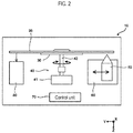
- the detection device 10 includes a support member 30, a rotation unit 40, a magnet 50, a transfer unit 60, a control part 70, and a detection unit 80.
- the cartridge 20 is installed on the support member 30.
- the rotation unit 40 includes a motor 41 and a rotating shaft 42.
- the rotating shaft 42 extends in the vertical direction.
- the upper end of the rotating shaft 42 is fixed to the support member 30, and the lower end of the rotating shaft 42 is fixed to the drive shaft of the motor 41.
- the rotation unit 40 drives the motor 41 to rotate the cartridge 20 installed on the supporting member 30 around the rotating shaft 42.
- Magnet 50 collects magnetic particles spread within the chamber 100.
- the target substance and the labeling substance are bound to the magnetic particles in the chamber 100 as described above.
- the magnet 50 may be configured by a permanent magnet or an electromagnet.
- the transfer unit 60 moves the magnet 50 in a direction different from the circumferential direction in the horizontal plane. Specifically, the transfer unit 60 moves the magnet 50 in the radial direction. The transfer unit 60 also moves the magnet 50 in the vertical direction. That is, the transfer unit 60 moves the magnet 50 toward and away from the rotating shaft 42, and moves the magnet 50 toward and away from the cartridge 20.
- the transfer unit 60 is configured to shift the magnet 50 in a direction shifted from the radial direction.
- the transfer unit 60 also may move the magnet 50 in a direction inclined from the vertical direction.
- the transfer unit 60 also may change the relative position between the magnet 50 and the cartridge 20.
- the transfer unit 60 also may move the cartridge 20 by moving the support member 30 supporting the cartridge 20 so that the magnet 50 is moved relative to the cartridge 20.
- the detection device 10 may be increased in size since a structure for moving the support member 30 is separately required. Therefore, it is desirable that the support member 30 is not moved and the magnet 50 is moved relative to the cartridge 20.
- the control unit 70 controls the rotation unit 40 and the transfer unit 60. Referring to FIG. 1A , the control unit 70 drives the transfer unit 60 to bring the magnet 50 close to the cartridge 20 at a position facing the first chamber 100a, and the magnetic force of the magnet 50 causes the magnetic particles of the complex to be collected by the magnet 50. Thereafter, the control unit 70 causes the transfer unit 60 to maintain a state where the magnet 50 approaches the cartridge 20 until the magnetic particles are moved to the second chamber 100b.
- the control unit 70 moves the magnetic particles collected by the magnet 50 in the first chamber 100a from the first chamber 100a to the flow channel 22. Subsequently, the control unit 70 moves the magnetic particles collected by the magnet 50 in the flow channel 22 by rotating the cartridge 20. Subsequently, the control unit 70 moves the magnet 50 in a radial direction from a position facing the flow path 22, thereby moving the magnetic particles collected by the magnet 50 from the flow path 22 to the second chamber 100b. Note that when the magnetic particles are transferred from the first chamber 100a to the second chamber 100b, the magnetic particles are moved from the liquid phase region of the first chamber 100a to the liquid phase region of the second chamber 100b through the gaseous phase region of the flow path 22.
- control unit 70 drives the transfer unit 60 to move the magnet 50 in a direction approaching the rotating shaft 42, so that the magnetic particles in the first chamber 100a pass through the first flow path 22a to the connecting portion 22d. Subsequently, the control unit 70 drives the rotation unit 40 to rotate the cartridge 20, thereby moving the magnetic particles positioned in the connecting portion 22d to the connecting portion 22e through the third channel 22c. The control unit 70 also drives the transfer unit 60 to move the magnet 50 in a direction away from the rotating shaft 42, so that the magnetic particles positioned at the connection unit 22e are transmitted through the second flow path 22b to the second chamber 100b. Thereafter, the control unit 70 drives the transfer unit 60 to move the magnet 50 in a direction away from the cartridge 20. In this way the target substance bound to the magnetic particles is accommodated in the second chamber 100b.
- the rotation unit 40 when moving the magnetic particles positioned in the connecting portion 22d to the connecting portion 22e, the rotation unit 40 also may move the magnet 50 relative to the cartridge 20.
- the rotation unit 40 also may move the magnet 50 in the circumferential direction.
- a structure for moving the magnet 50 in the circumferential direction is additionally required, so that the detection device 10 may be increased in size. Therefore, it is preferable that the magnet 50 is not moved, and the cartridge 20 is rotated in the circumferential direction.
- the control unit 70 also sequentially transfers the magnetic particles to the plurality of chambers as described above.
- the detection unit 80 detects light generated from the sample in the second chamber 100b. This detection is based on chemiluminescence, and chemiluminescence will be described later with reference to FIGS. 8 to 11C .
- the control unit 70 analyzes the target substance based on the light detected by the detection unit 80.
- the target substance in the first chamber 100a can be collected together with the magnetic particles by the magnet 50 and, due to the movement of the magnet 50 in the radial direction and the rotation of the cartridge 20, the target substance can be moved to the second chamber 100b together with the magnetic particles.
- two protrusions 130 are provided in the first chamber 100a and the second chamber 100b, respectively, so as to be arranged in the circumferential direction. These two protrusions 130 stabilize the liquid level of the sample accommodated in the first chamber 100a and the second chamber 100b, and have an action of locating the sample at a predetermined position substantially uniformly in the first region 110. In this way the magnetic particles are suppressed from being left behind by the magnet since the liquid level of the sample is stabilized.
- the fluorescence generated by the labeling substance can be accurately and stably detected since the sample is substantially fixed at a position in the chamber 100 when the liquid level of the sample is stabilized.
- the protrusion 130 is not provided in the chamber 400 according to the comparative example. Therefore, the chamber 400 is not divided into the first region and the second region by the protrusion 130.
- the chamber 400 is connected to the flow path 22 on the side of the rotating shaft 42, and has protrusions 410 protruding in a circular arc shape on the side of the rotating shaft 42 on both sides sandwiching a portion connected to the flow path 22.
- the liquid level of the sample is inclined as shown by the solid line in FIG. 3A whereas, alternatively, as shown by the broken line in FIG. 3A , the liquid level of the sample may incline in the opposite direction. That is, in the chamber shape of the comparative example, the state of the liquid surface at the time rotation stops can become unstable. For this reason, for example, when the magnet 50 is positioned at the position shown in FIG. 3A in order to collect the magnetic particles, it may be difficult to collect the magnetic particles in the sample near the protrusion 410 which is greatly distant from the position of the magnet 50, such that the magnetic particles may remain in the chamber 400.
- the detection accuracy may decrease.
- the detection unit 80 is configured to capture the fluorescence generated from the sample by a photodetector 82 to which the light is guided by a tubular light guide unit 81
- the amount of fluorescence captured by the light guide unit 81 fluctuates depending on whether the sample is accommodated in the center or the sample is accommodated at the end of the chamber 400. For this reason, if the liquid level of the sample accommodated in the chamber 400 is unstable as shown in FIG. 3A , the amount of fluorescence taken into the light guide unit 81 becomes unstable, and as a result the accuracy of detection of the target substance is reduced.
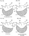
- the sample accommodated in the chamber 100 is restrained by the protrusions 130 on bilateral sides in the circumferential direction after stopping the rotation of the cartridge 20, such that the liquid surface is stabilized by the surface tension and the wettability between the protrusions 130 and the sample, and the sample is readily situated at a predetermined position within the first region 110.
- the magnet 50 when the magnet 50 is positioned at the position shown in FIG. 4A , for example, magnetic particles are smoothly collected from all the sample in the first region 110, and residual magnetic particles remaining in the chamber 100 is suppressed. Since the sample is stably situated in the center of the first region 110 in this way as shown in FIG. 4B , the sample is substantially constant with respect to the entrance of the light guiding unit 81 of the detection unit 80. Therefore, fluctuation of the fluorescence uptake amount due to deviation of the sample does not occur. Hence, the detection accuracy of the target substance can be improved.
- the chamber 100 is a region in which a sample is accommodated, and is provided with a first region 110 at a position away from the rotating shaft 42 and a second region 120 arranged at a position near the rotating shaft 42.
- the chamber 100 also includes a protrusion 130 protruding toward the inner side of the chamber 100 in the circumferential direction.
- a protrusion 130 protruding toward the inner side of the chamber 100 in the circumferential direction.
- two protrusions 130 arranged in the circumferential direction are provided, but only one protrusion also may be provided.
- the protrusion 130 surrounded by the larger circle of the broken line in FIG. 5A is configured as shown in FIG. 5B when it is enlarged.
- the protrusion 130 protrudes from a position between the first region 110 and the second region 120.
- the first region 110 is "the region where the sample is stored", but this does not mean only the region occupied by the sample when the sample is accommodated in the chamber 100, and also includes the region where the sample can be accommodated.
- the first area 110 will be described specifically.
- a boundary L between the first region 110 and the second region 120 is indicated by a broken line.
- this boundary L is a line extending in the circumferential direction from the tip 132 of the tip portion 131 of the protrusion 130.
- the first region 110 and the second region 120 are separated by a boundary L.
- the boundary L also includes an approximate straight line.
- a specific area of the second area 120 will be described later. Note that since the shape of the chamber 100 shown in FIG. 5A is bilaterally symmetrical in the Y-axis direction, the lines extending in the circumferential direction from the tips 132 of the protrusions 130 on both sides are the same.
- the protrusion 130 has a curved surface recessed inwardly of the chamber 100, and which is defined as a tip portion 131. At the tip portion 131, the tip 132 is positioned innermost of the chamber 100.
- the connecting part 133 is a curved surface.
- the inner side surface 121 of the second region 120 is formed so as to be separated from the rotating shaft 42 toward the tip portion 131 of the protrusion 130.
- the protrusion 130 is an inner surface remote from the rotating shaft 42, wherein the inner surface 134 which continues from the tip portion 131 of the protrusion 130 to the first region 110 has a curved surface recessed inwardly of the protrusion 130.
- the tip portion 131 is shown curved to the inner side the chamber 100.
- the angle ⁇ formed by the tangent line L1 and the tangent line L2 at each of the point P and the point Q which are the boundaries of a range in which the curvature is substantially constant, is set to an angle close to 90 degrees, for example, in the range of 80 degrees to 120 degrees.
- the sample accommodated in the first region 110 can be suppressed from overriding the protrusion 130 due to the surface tension as shown by the dotted line arrow in FIG. 6B and prevented from moving to the second region 120.
- angle ⁇ formed by the tangent line L1 and the tangent line L2 is not limited to the range of 80 degrees to 120 degrees and may be a more acute angle.
- the angle ⁇ formed by the tangential line L 1 and the tangent line L 2 can be appropriately adjusted depending on the shape of the protrusion 130, the characteristics of the sample accommodated in the chamber 100, and the like.
- the tip portion 131 of the protrusion 130 is curved as shown in FIG. 5B , but the protrusion 130 itself also may be formed to have an acute angle.
- the chamber 100 has the following effects.
- the depth of the protrusion 130 protruding inside the chamber 100 is not particularly limited as long as the liquid level of the sample accommodated in the chamber 100 is stabilized.
- a distance of a first width which is the largest width in the circumferential direction of the first region 110, is designated a distance D1
- a straight line bisecting the first width in the radial direction of the rotating shaft 42 is designated a straight line A
- a distance of a second width which is a width in the circumferential direction between the straight line A and the tip 132 of the protrusion 130
- the distance corresponding to half of the first width is designated a distance D3, as shown in FIG. 5A .
- the distance D2 is in the range of 40% to 98% of the distance D3
- the liquid level of the sample can be stabilized.
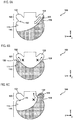
- the sample in the chamber 100 moves from the first region 110 to the second region 120 during the rotation operation of the chamber 100 as indicated by the outline arrow in FIG. 6A , the sample in the chamber 100 moves along the inner side surface 121 of the second region 120 due to centrifugal force and returns to the first region 110. Since the connecting part 133 is a curved surface, the sample scarcely remains on the connecting part 133 when the sample moves to the first region 110 along the inner surface 121 of the second region 120 due to the centrifugal force. Hence, the sample can be accommodated in the first region 110 without loss of sample.
- the sample moving from the first region 110 to the second region 120 during the rotation operation moves from the base of the protrusion 130 to the top portion 131 by centrifugal force. Hence, the sample does not remain on the rotation shaft side of the protrusion. As described above, even when the sample moves to the second region 120, the sample does not override the protrusion 130 and stay in the second region 120. Therefore, the sample can be reliably accommodated in the first region 110 without loss of sample.
- the sample When the sample is moved toward the protrusion 130 along the inner side surface 111 of the first region 110 by the inertial force and the rotation operation is stopped, the sample flows toward the first region 110 since the direction of travel of the sample from the top portion 131 of the protrusion 130 along the inner side surface 134 to the first region 110 changes smoothly. Hence, the sample can be reliably contained in the first region 110. Since the angle ⁇ formed by the tangent line L1 and the tangent line L2 is 80 degrees to 120 degrees, the sample accommodated in the first region 110 is restricted from overriding the protrusion 130 and moving to the second region 120 due to surface tension as shown by the dotted arrow in FIG. 6B . Hence, it is possible to reliably contain the sample in the first region 110.
- the flow path 22 is connected to the portion of the second region 120 closest to the rotating shaft 42.
- the second region 120 is provided with protrusion regions 122 which protrude toward the rotating shaft 42 on both sides in the circumferential direction across this portion.
- FIG. 6C even if the sample in the first region 110 moves to the second region 120 beyond the protrusion 130 during the rotation operation of the cartridge 20, it is received in the protrusion region 122. Therefore, as shown by a dotted line arrow in FIG. 6C , leakage of the sample from the second region 120 to the flow path 22 is suppressed, and the sample can reliably be retained in the chamber 100.
- the inner side surface 123 of the protrusion region 122 is a curved surface.
- the sample that has moved to the second region 120 beyond the protrusion 130 during the rotational movement changes direction of travel toward the first region 110 while moving along the inner surface of the protrusion region 122.
- the sample that has moved to the second region 120 is returned to the first region 110.
- the sample can be reliably contained in the first region 110.
- an opening 124 is formed in the second region 120 to connect with the flow path 22 .
- the region from the boundary L to the opening 124 is the region of the second region 120.
- the volume of the first region 110 also is greater than 1 time and less than 2 times the amount of the sample to be contained in the first region 110. Therefore, the sample can be stably accommodated in the first region 110 by the wettability and surface tension of the projection 130.
- the shape of the chamber 100 shown in FIG. 5A also is symmetrical in the circumferential direction. In this way the sample can be uniformly accommodated in the first region 110 in the circumferential direction. Whichever direction the cartridge 20 is rotated, the second region 120 can receive the sample in a well-balanced manner. Therefore, since the magnetic particles collect near the center of the chamber 100, that is, the first region 110, the magnetic particles are easily taken out by the magnet 50.
- the chambers 100 provided in the cartridge 200 are identical chambers, but in this case, in order to distinguish chambers from FIG. 1A to FIG. 6C , different reference numerals are given to the respective chambers. Note that the chambers 211 to 216 in the cartridge 200 shown in FIG. 7A are all described as chambers having the same shape and capacity.
- the cartridge 200 is composed of a plate-like and disk-shaped substrate 200a. Each part in the cartridge 200 is formed by gluing a concavity formed in the substrate 200a and a film (not shown) covering the entire surface of the substrate 200a.
- the substrate 200 a and the film bonded to the substrate 200a are made of light-transmitting members.
- a hole 201 On the substrate 200a, there are provided a hole 201, chambers 211 to 216, a channel 220, five reagent containers 231, a reagent container 232, an opening 241, a separating portion 242, and a channel 243.
- the hole 201 penetrates the substrate 200a at the center of the substrate 200a.
- the chambers 211 to 216 are arranged in the circumferential direction in the vicinity of the outer periphery of the substrate 200a.
- the cartridge 200 is installed in the detection device 10 so that the center of the hole 201 coincides with the rotating shaft 42.
- the flow path 220 includes an arcuate first flow path 221 extending in the circumferential direction and six second flow paths 222 extending in the radial direction.
- the first flow path 221 is connected to the six second flow paths 222.
- the six second flow paths 222 are connected to the chambers 211 to 216, respectively.
- the five reagent containers 231 are connected to the flow path 220 via the flow paths and are on the extension lines of the second flow paths 222 connected to the chambers 211 to 216, respectively.
- the reagent containing portion 232 is connected to a flow path connecting the second flow path 222 connected to the chamber 216 and the reagent container 231 on the extension line of the second flow path 222 connected to the chamber 216 via the flow path.
- a sealing body 231a is provided on the inner side top surface in the radial direction.
- the sealing body 231a is opened by being pushed from above by a stopper opening portion (not shown). In this way the inside of the reagent container 231 is connected to the outside of the cartridge 200 at the position of the sealing body 231a.
- the reagent container 232 is also provided with a sealing body 232a on the inner side top surface in the radial direction.
- a sealing body 232a is opened by a stopper opening portion (not shown), the inside of the reagent container 232 is connected to the outside of the cartridge 200 at the position of the seal 232a.
- a blood sample of whole blood collected from the subject is injected into the separating portion 242 through the opening 241.
- the separating portion 242 separates the injected blood sample into blood cells and plasma.
- the plasma separated by the separating portion 242 moves to the channel 243.
- a hole 243a is provided on the radially inner top surface of the flow path 243.
- each structure of the substrate 200a is formed only in a region of one-third of the substrate 200a as shown in FIG. 7A .
- the present invention is not limited to this configuration inasmuch as a group of these configurations may be formed in the remaining two-thirds region, and three groups of structures may be provided on the substrate 200a.
- the detection device 10 is mounted on, for example, the analyzer 300 shown in FIG. 7B .
- the analyzer 300 detects a target substance in a sample using an antigen-antibody reaction, and analyzes the target substance based on the detection result.
- the analyzer 300 includes a main body 301 and a lid 302.
- the main body 301 the portion other than the portion facing the lid 302 is covered with the housing 301a.
- the lid 302 the portion other than the portion facing the main body 301 is covered with the housing 302a.
- the main body 301 supports the lid 302 so as to be openable and closable. When attaching and detaching the cartridge 200, the lid 302 is opened as shown in FIG. 7B .
- a cartridge 200 is installed on the upper portion of the main body 301.
- the operation of the detection device 10 will be described next with reference to FIG. 8 .
- the target substance in the blood sample contains, for example, an antigen.
- the antigen is hepatitis B surface antigen (HBsAg).
- the target substance may be one or more of an antigen, an antibody, or a protein.
- Prescribed reagents are stored in advance in the reagent containers 231 and 232 of the cartridge 200 and the chamber 211.
- the R1 reagent is accommodated in the reagent container 231 located in the radial direction of the chamber 211.
- the R2 reagent is accommodated in the chamber 211.
- the R3 reagent is accommodated in the reagent container 231 located in the radial direction of the chamber 212.
- the cleaning liquid is contained in the reagent container 231 located in the radial direction of the chambers 213 to 215.
- the R4 reagent is contained in a reagent container 231 located in the radial direction of the chamber 216.
- the reagent container 232 accommodates the R5 reagent.
- the control unit 70 acquires the rotational position of the drive shaft of the motor 41 based on the output signal of the encoder (not shown) connected to the motor 41.
- the control unit 70 acquires the circumferential position of the cartridge 200 by detecting a predetermined portion of the rotating cartridge 200 with a sensor.
- the cartridge 200 may be installed at a predetermined position with respect to the support member 30. In this way the control unit 70 can position each part of the cartridge 200 at a predetermined position in the circumferential direction.
- step S11 when the control unit 70 starts the processing in step S12 and the following steps when the operator installs the cartridge 200.
- step S12 the control unit 70 transfers the plasma and the reagent to the chamber.
- control unit 70 drives the motor 41 to rotate the cartridge 200. Then, the controller 70 drives the motor 41 to rotate the cartridge 200, transfer the plasma positioned in the region 243b to the chamber 211 by centrifugal force, and transfer the reagents accommodated in the six reagent containers 231 to the chambers 211 - 216. In this way in the chamber 211, plasma, R1 reagent, and R2 reagent are mixed. The R3 reagent is transferred to the chamber 212, the cleaning liquid is transferred to the chambers 213 - 215, and the R4 reagent is transferred to the chamber 216.
- step S12 when the transfer of the plasma and the reagent is completed, the control unit 70 also performs the stirring process. Specifically, the control unit 70 drives the motor 41 so as to switch between two different rotation speeds at predetermined time intervals while rotating in a predetermined direction. For example, the control unit 70 performs a stirring process by switching the current applied to the motor 41 at predetermined time intervals, or switching the driving of the motor 41 between on and off at predetermined time intervals. In this way the Euler force generated in the circumferential direction changes at predetermined time intervals, whereby the sample in the chambers 211 to 216 is stirred.
- Such a stirring process is performed not only in step S12 but also in steps S13 to S18 in the same manner after the transfer process.
- control unit 70 also may perform the stirring process by switching the rotation direction of the motor 41 at predetermined time intervals. However, when the motor 41 is thus driven, the load of the motor 41 is increased. Therefore, as described above, it is preferable that the motor 41 is driven so as to switch between the two rotation speeds while rotating in a predetermined direction.
- the stirring process in step S12 will be described in detail later with reference to FIGS. 12 and 13 .
- the R1 reagent contains a capture substance that binds to the target substance.
- the capture substance includes, for example, an antibody that binds to the target substance.
- the antibody is, for example, a biotin-conjugated HBs monoclonal antibody.
- the R2 reagent contains magnetic particles in the sample component. Magnetic particles are, for example, streptavidin-bound magnetic particles whose surface is coated with avidin.
- step S12 when the plasma, the R1 reagent, and the R2 reagent are mixed and stirred, the target substance and the R1 reagent are bound by the antigen-antibody reaction.
- the target substance bound to the capture substance of the R1 reagent binds to the magnetic particle via the capture substance. In this way, a complex is generated in a state where the target substance and the magnetic particles are bonded.
- the control unit 70 transfers the complex in the chamber 211 from the chamber 211 to the chamber 212.
- the complex generated in the chamber 211 and the R3 reagent are mixed in the chamber 212.
- the R3 reagent contains a labeling substance.
- the labeling substance includes a capture substance that specifically binds to the target substance and a label.
- the labeling substance is a labeled antibody in which an antibody is used as a capture substance.
- the complex generated in the chamber 211 reacts with the labeled antibody contained in the R3 reagent. In this way a complex is formed in which the target substance, the capture substance, the magnetic particles, and the labeled antibody are bound.
- step S13 will be described in detail with reference to FIG. 9 .
- the flowchart in FIG. 9 is a flowchart showing in detail step S13 in FIG. 8 .
- step S13 in FIG. 8 .
- FIGS. 10A to 11C refer to the state transition diagrams of FIGS. 10A to 11C as appropriate while referring primarily to FIG. 9 .
- step S12 as shown in FIG. 10A , the complex spreads in the chamber 211 before the stirring process is performed.
- the chamber 211 according to the first embodiment is a chamber having the shape described with reference to FIGS. 5A and 5B , the magnetic particles collect together when the sample is agitated in step S12.
- the complex in the chamber 211 can be efficiently collected by the magnet 50.
- step S102 the control unit 70 drives the transfer unit 60 to move the magnet 50 in a direction approaching the rotating shaft 42, and moves the complex to the connecting portion of the second flow path 222connected to the chamber 211 and the first flow path 221.
- step S103 the control unit 70 drives the motor 41 to rotate the cartridge 200, and as shown in FIG. 11A , the control unit 70 moves the complex to the connecting portion of the second flow path 222 connected to the chamber 212 and the first flow path 221.
- the speed at which the complex is moved with respect to the cartridge 200 in step S103 is set similarly to the case of step S102.
- the rotation of the cartridge 200 by the motor 41 is performed so as to realize the moving speed of the complex as described above.
- step S104 the control unit 70 drives the transfer unit 60 to move the magnet 50 in a direction away from the rotating shaft 42, and transfers the complex to the chamber 212 as shown in FIG. 11B .
- the speed at which the complex is moved with respect to the cartridge 200 in step S104 is set similarly to step S102.
- step S105 the control unit 70 drives the transfer unit 60 to move the magnet 50 away from the cartridge 200, and spreads the composite inside the chamber 212 as shown in FIG. 11C .
- control unit 70 moves the magnet 50 to the flow path 220 to position the magnet 50 opposite the chamber 212. Thereafter, the control unit 70 separates the magnet 50 from the cartridge 200, and releases the magnetism of the complex induced by the magnet 50.
- step S106 the control unit 70 performs the stirring process described above. At this time, before the stirring process, the magnetism of the composite is released and the complex spreads in the chamber 212, so that the sample in the chamber 212 is reliably stirred.
- step S13 in FIG. 8 is performed as described above. Note that the transfer process and the stirring process shown in steps S101 to S106 are similarly performed in steps S14 to S17 described later.
- step S14 the control unit 70 transfers the complex in the chamber 212 from the chamber 212 to the chamber 213. In this way in the chamber 213 the complex generated in the chamber 212 and the cleaning liquid are mixed.
- step S14 when the complex generated in the chamber 212 and the cleaning liquid are mixed and stirred, the complex and the unreacted substance are separated in the chamber 213. That is, unreacted substances are removed by cleaning in the chamber 213.
- step S15 the control unit 70 transfers the complex in the chamber 213 from the chamber 213 to the chamber 214. In this way the complex generated in the chamber 212 and the cleaning liquid are mixed in the chamber 214. Even in the chamber 214, unreacted substances are removed by cleaning.
- step S16 the control unit 70 transfers the complex in the chamber 214 from the chamber 214 to the chamber 215. In this way the complex generated in the chamber 212 and the cleaning liquid are mixed in the chamber 215. Unreacted substances are removed by cleaning even in chamber 215.
- step S17 the control unit 70 transfers the composite in the chamber 215 from the chamber 215 to the chamber 216.
- the complex generated in the chamber 212 and the R4 reagent are mixed in the chamber 216.
- the R4 reagent is a reagent for dispersing the complex generated in the chamber 212.
- the R4 reagent is, for example, a buffer solution.
- step S17 when the complex generated in the chamber 212 and the R4 reagent are mixed and stirred, the complex generated in the chamber 212 is dispersed.
- step S18 the control unit 70 transfers the R5 reagent to the chamber 216.
- control unit 70 drives the motor 41 to rotate the cartridge 200. Then, the control unit 70 drives the motor 41 to rotate the cartridge 200, and transfers the R5 reagent stored in the reagent container 232 to the chamber 216 by centrifugal force. In this way the R5 reagent is further mixed with the mixed solution generated in step S17 in the chamber 216.
- the R5 reagent is a luminescent reagent comprising a luminescent substrate that produces light upon reaction with a labeled antibody bound to the complex.
- step S18 when the mixed solution produced in step S17 and the R5 reagent are mixed and stirred, a sample is prepared. This sample chemilumineses by reacting the labeling substance bound to the complex with the luminescent substrate.
- step S19 the control unit 70 drives the motor 41 to position the chamber 216 right above the detection unit 80, and detects the light generated from the chamber 216 by the photodetector 82.
- step S20 the control unit 70 performs analysis processing related to immunity based on the light detected by the photodetector 82.
- the photodetector 82 is configured by a photomultiplier tube, a pulse waveform corresponding to the photon reception is output from the photodetector 82.
- the detection unit 80 counts photons at regular intervals based on the output signal of the photodetector 82 and outputs a count value. Based on the count value output from the detection unit 80, the control unit 70 analyzes the presence or absence and the amount of the target substance.
- the complex is sequentially transferred in the chambers 211 to 216.
- the complex is transported through a plurality of chambers in this manner, the complex is likely to be left behind in the chambers 211 to 215 and the flow path 220.
- chemiluminescence is light emitted using energy by chemical reaction, for example, light emitted when a molecule is excited by a chemical reaction to an excited state and returns to the ground state from the excited state.
- Chemiluminescence can be generated, for example, by reaction between an enzyme and a substrate by applying an electrochemical stimulus to a labeling substance, or based on the LOCI method (Luminescent Oxygen Channeling Immunoassay). In the first embodiment, any chemiluminescence may be performed.
- a substance excited with fluorescence and a target substance may be combined to constitute a complex.
- a light source is arranged to irradiate light on the chamber 216.
- the photodetector 82 detects the fluorescence excited from the substance bound to the complex by the light from the light source.
- the magnetic particles may be particles used for ordinary immunoassay that contain a magnetic material as a base material.
- a magnetic material for example, magnetic particles using Fe 2 O 3 and/or Fe 3 O 4 , cobalt, nickel, ferrite, magnetite or the like can be used as the base material.
- the magnetic particles may be coated with a binding substance for binding to the target substance, or may be bound to the target substance via a capture substance for binding the magnetic particles and the target substance.
- the capture substances are magnetic particles and antigens or antibodies which mutually bind to the target substance.
- the labeling substance also includes, for example, a capture substance that specifically binds to the target substance and a label for chemiluminescence.
- the capture substance is not particularly limited insofar as it specifically binds to the target substance.
- the capture substance binds to the target substance by an antigen-antibody reaction. More specifically, although the capture substance is an antibody in the first embodiment, when the target substance is an antibody, the capture substance may be an antigen of the antibody. When the target substance is a nucleic acid, the capture substance may be a nucleic acid complementary to the target substance.
- an enzyme, a fluorescent substance, a radioactive isotope and the like can be mentioned.
- the enzyme examples include alkaline phosphatase (ALP), peroxidase, glucose oxidase, tyrosinase, acid phosphatase and the like.
- ALP alkaline phosphatase
- peroxidase glucose oxidase
- tyrosinase glucose oxidase
- acid phosphatase acid phosphatase
- the label is not particularly limited insofar as it is a substance that emits light by electrochemical stimulation, for example, a ruthenium complex.
- fluorescent substances fluorescein isothiocyanate (FITC), green fluorescent protein (GFP), luciferin and the like can be used.
- FITC fluorescein isothiocyanate
- GFP green fluorescent protein
- luciferin luciferin
- the radioactive isotope 1251, 14C, 32P and the like can be used
- a known luminescent substrate may be appropriately selected according to the enzyme to be used as the luminescent substrate for the enzyme.
- the following examples can be used as a chemiluminescent substrate: when alkaline phosphatase is used as an enzyme, CDP-Star (registered trademark), (4-chloro-3- (methoxyspiro [1,2-dioxetane-3,2'-(5'-chloro) Trioxysilo [3.3.1.1 3,7] decane] -4-yl) phenyl phosphate), CSPD (registered trademark) (3- (4-methoxyspiro [1,2-dioxetane- 3, 2- (5'-chloro) tricyclo [3.3.1.13,7] decane] -4-yl) phenyl phosphate); luminescent substrates such as p-nitrophenyl phosphate, 5-bromo-4-chloro-3-indolyl phosphate (BCIP), 4-
- the stirring process in step S106 will be described in detail.
- the stability of the liquid surface of the sample in the chamber 100 immediately after stirring is important.
- the cartridge 200 suddenly stops rotating, the liquid surface of the sample undulates severely in the chamber 100, and it may take time until the liquid surface becomes stable. Due to severe undulation, there also is a possibility that a part of the sample may override the protrusion 130 of the chamber 100 and further leak from the second region 120 to the second flow path 222 of the flow path 220.
- the rotation operation of the cartridge 200 according to the first embodiment is controlled as follows.
- the stirring of the sample that is, the control of the rotation operation of the cartridge 200 will be described.
- the chamber 100 rotates.
- the control unit 70 decreases the rotation speed after increasing the rotation speed of the cartridge 200. Meanwhile, a magnetic force is applied to the magnetic particles, and the magnetic particles move in the radial direction of the rotating shaft 42 to collect the target substance.
- the control unit 70 sets the rotation of the cartridge 200 to 9.375 (r/m), and the rotation unit 40 is controlled such that the rotation of the cartridge 200 increases from 9.375 (r/m) to 360 (r/m) over 2 seconds from the start of stirring.
- the control unit 70 controls the rotating unit 40 so as to maintain the rotation of the cartridge 200 at 360 (r/m) for 1 second two seconds from the start of stirring.
- the rotation number of the cartridge 200 is increased from 360 (r/m) to 460 (r/m) and lowered again to 360 (r/m).
- the rotation unit 40 is caused to execute this in 0.04 seconds as one cycle.
- the control unit 70 causes the cartridge 200 to execute the above rotation for 370 cycles, that is, for 14.8 seconds. Thereafter, the control unit 70 controls the rotation unit 40 to rotate the cartridge 200 from 360 (r/m) to 9.375 (r/m) over 3.949 seconds.
- step S201 the control unit 70 once increases the rotation speed of the cartridge 200 over a predetermined time. That is, in the graph of FIG. 12 , when the rotation number of the cartridge 200 reaches 9.375 (r/m), the control unit 70 increases the rotation speed of the cartridge 200 to a predetermined value and rotates the cartridge 200 to the rotation unit 40. This predetermined value differs for each target substance.
- step S202 the control unit 70 maintains the rotation speed of the cartridge 200 raised to a predetermined value in step S201 to be constant for a predetermined time.
- step S203 the control unit 70 decreases the rotation speed of the cartridge 200 over a predetermined time.
- the control unit 70 controls the rotation unit 40 to slacken the rotation of the cartridge 200.
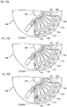
- steps S202 and S203 the sample oscillates in the chamber 100 to the left and right of the Y axis as shown in FIGS. 14B and 14C .
- step S204 the control unit 70 stops the rotation of the cartridge 200 in the rotation unit 40. At this time, as shown in FIG. 14D , the sample in the chamber 100 is accommodated in the first region 110 with the projection 130 as a boundary, and the liquid level is stabilized.
- the liquid surface of the sample in the chamber 100 is stabilized, and the magnetic particles gather near the center of the first region 110. Therefore, the magnetic particles in the chamber 100 are smoothly transferred by the magnet 50 without being left behind.
- a set of protrusions 130 aligned in the circumferential direction is disposed in the radial direction, and another set of projections also may be formed.
- the protrusion that is distant from the rotating shaft 42 is the protrusion 130
- the other protrusion that is formed closer to the rotating shaft 42 is the protrusion 140.
- a line extending in the circumferential direction passing through the tip 132 of the protrusion 130 is defined as a boundary L which distinguishes between the first area 110 and the second area 120. In this way the liquid level of the sample can be reliably stabilized.
- the protrusion closer to the rotating shaft 42 is defined as the protrusion 130
- the other protrusion that is formed farther from the rotating shaft 42 is the protrusion 140.
- the first region 110 and the second region 120 are distinguished by a line extending in the circumferential direction through the tip 132 of the protrusion 130 closer to the rotating shaft 42 that is designated as a boundary L. In this way the liquid level of the sample can be reliably stabilized.
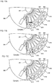
- the sample can be stably accommodated in the first region 110 by selecting the most suitable protrusion 130 when using the chamber 100 as shown in FIGS. 15A and 15B .
- the amount of the sample and the reagent introduced into each chamber 100 may vary according to the measurement item.
- two kinds of samples can be dealt with by using the chamber 100 shown in FIGS. 15A and 15B .
- the cartridge 200 can be used in a versatile manner.
- a set of protrusions configured by a set of protrusions 130 arranged in the circumferential direction may be three or more. In this way the type of liquid volume that can be handled is further increased.
- the protrusion 130 may be provided, and the other protrusions 140 may be provided at different positions in the radial direction.
- a protrusion 130 is formed at a position close to the rotating shaft 42 on the Y axis positive side, and a protrusion 140 is formed at a position different from that of the protrusion 130 in the radial direction, that is, on the Y axis negative side. In this way when the amount of the sample is small, the liquid level can be stabilized by the protrusion 130.
- a protrusion formed at a position distant from the rotating shaft 42 on the positive side of the Y axis is defined as the protrusion 130, and a protrusion 140 is formed on the Y axis negative side at a position different from the protrusion 130 in the radial direction.
- the liquid surface can be stabilized by the protrusion 130 with the boundary between the first region 110 and the second region 120 as a boundary L. That is, the space of the first region 110 can be expanded according to the amount of the sample.
- the effect of stabilizing the liquid level is slightly reduced.
- the liquid level can be stabilized by the surface tension and the wettability between the protrusion 130 and the sample.
- the protrusion 130 may be formed in the radial direction, and the other protrusion 140 may be formed at three or more positions different from the protrusion 130.
- the liquid level can be stabilized by the surface tension and the wettability between the protrusion 130 and the sample.
- the protrusion 130 is formed on the Y axis positive side in FIG. 15E
- the protrusion 130 also may be formed on the Y axis negative side.
- the protrusion 130 and the other protrusion 140 also may have different protrusion heights in the inward direction of the chamber 100 in the configurations of FIGS. 15A and 15B .
- the sample when a large amount of sample is introduced into the chamber 100, the sample overrides the projection 130 to the inner side surface 123 of the protrusion region 122, and there is a possibility of leakage of the sample into the flow path 220.
- the protrusion formed closer to the rotating shaft 42 which is formed so as to protrude deeper into the chamber 100 is the protrusion 130. In this way it is difficult for the sample to move to the protrusion region 122, and it is possible to more reliably prevent the sample from moving from the protrusion region 122 to the flow channel 220.
- the chamber 100 shown in FIG. 15F can use a protrusion located farther from the rotating shaft 42 as the protrusion 130. In this case, the protrusion at the position close to the rotary shaft 42 becomes another protrusion 140.
- a support member 510 is disposed instead of the support member 30, and a cartridge 520 is used instead of the cartridge 200.
- the support member 510 includes a hole 511 and three installation parts 512.
- the hole 511 is provided at the center of the support member 510.
- the support member 510 is installed on the rotating shaft 42 via a predetermined member. In this way the support member 510 can rotate around the rotating shaft 42.
- Three installation parts 512 are provided in the circumferential direction.
- the installation part 512 includes a surface 512a and a hole 512b.
- the surface 512a is one stage lower than the upper surface of the support member 510.
- the hole 512b is formed at the center of the surface 512a and passes through the support member 510 in the vertical direction.
- the cartridge 520 has a rectangular shape and has the same configuration as the cartridge 200.
- the operator injects the blood sample into the cartridge 520 and installs the cartridge 520 in the setting unit 512.
- the control unit 70 drives the motor 41, the transfer unit 60, and the detection unit 80.
- the complex in the cartridge 520 is reliably transported by the magnet 50. Therefore, as in the first embodiment, it is possible to maintain high analytical accuracy of the target substance by the detection device 10.
- the cartridge 520 since the cartridge 520 also can be installed in each of the three installation parts 512, analysis can be performed on three cartridges 520 at the same time.
Landscapes
- Chemical & Material Sciences (AREA)
- Chemical Kinetics & Catalysis (AREA)
- Health & Medical Sciences (AREA)
- Hematology (AREA)
- Life Sciences & Earth Sciences (AREA)
- Immunology (AREA)
- Analytical Chemistry (AREA)
- General Health & Medical Sciences (AREA)
- Engineering & Computer Science (AREA)
- Clinical Laboratory Science (AREA)
- Dispersion Chemistry (AREA)
- Molecular Biology (AREA)
- Biomedical Technology (AREA)
- Urology & Nephrology (AREA)
- Biotechnology (AREA)
- Microbiology (AREA)
- Cell Biology (AREA)
- Food Science & Technology (AREA)
- Medicinal Chemistry (AREA)
- Physics & Mathematics (AREA)
- Biochemistry (AREA)
- General Physics & Mathematics (AREA)
- Pathology (AREA)
- Automatic Analysis And Handling Materials Therefor (AREA)
- Mixers With Rotating Receptacles And Mixers With Vibration Mechanisms (AREA)
- Sampling And Sample Adjustment (AREA)
Abstract
Description
- The present invention relates to a cartridge, a detection method, and a detection device for detecting a target substance.
- Japanese Patent Application Publication No.
2008-055405 - Specifically, as shown in
FIG. 17 , the substrate 1 is provided with afirst supply chamber 2 and a second supply chamber 3 in which two different types of fluids are respectively accommodated, and mixing chamber 4 in which the two different types of fluids are mixed. At least two kinds of fluids are sequentially stored in the mixing chamber 4. Thereafter, the substrate 1 is alternately rotated clockwise and counterclockwise until the fluids are mixed. The direction of rotation is changed in the other direction before thevortex flow 5 formed in the mixing chamber 4 disappears, by the rotation in either the clockwise direction or the counterclockwise direction. - Although at least two kinds of fluids contained in the mixing chamber 4 can be mixed rapidly in the method described in Japanese Patent Application Publication No.
2008-055405 2008-055405 - In this way, in order to smoothly and accurately perform the subsequent processing on the sample accommodated in the chamber, it is desirable to stabilize the liquid level of the sample to a predetermined state after a predetermined treatment such as centrifugation is applied to the sample contained in the chamber.
- In view of the above problems, the present invention provides a cartridge, a detection method, and a detection device capable of stabilizing the liquid level of a sample accommodated in a chamber in a predetermined state.
- A first aspect of the present invention relates to a cartridge (20) rotated about a rotating shaft (42) for detecting a target substance. The cartridge (20) according to this aspect comprises a chamber (100) containing a sample that includes a target substance. The chamber (100) comprises a first region (110) in which the sample is stored, a second region (120) arranged closer to the rotating shaft (42) than the first region (110), and a protrusion (130) projecting from between the first region (110) and the second region (120) to the inner side of the chamber (100).
- With this configuration, when the cartridge in the rotating state is stopped, the liquid level of the sample in the chamber can be stabilized to a predetermined state. In the cartridge (20) according to this aspect, the side surface of the protrusion (130) on the side of the rotating shaft (42) is formed so as to be away from the rotating shaft (42) as going toward the tip portion (131) of the protrusion (130).
- In this way, when a sample is accommodated in the chamber, the sample does not remain on the rotating shaft side of the protrusion. Therefore, the sample can be accommodated in the first region without loss of sample.
- In the cartridge (20) according to this aspect, the side surface of the protrusion (130) that is remote from the rotating shaft (42) may be formed to include a curved surface recessed inward of the protrusion (130).
- In this way when a sample is accommodated in the chamber and the rotation operation is stopped, the sample can be accommodated in the first region since the sample is directed to the first region.
- The cartridge (20) according to this aspect may be configured such that two protrusions (130) are provided at positions facing each other in the circumferential direction of the chamber (100).
- In this way when a sample is accommodated in the chamber, the sample can be stably accommodated in the first region.
- The cartridge (20) according to this aspect may be configured such that a set of two other protrusions (140) is provided in the radial direction of the rotation shaft (42). In this way when a sample is accommodated in the chamber, the sample can be stably accommodated in the first region.
- In the cartridge (20) according to this aspect, the protrusion (130) and another protrusion (140) may be provided at different positions in the radial direction of the rotation shaft (42).
- In this way when a sample is accommodated in the chamber, the sample can be stably accommodated in the first region.
- In the cartridge (20) according to this aspect, the volume of the first region (110) can be configured to be greater than 1 time and less than 2 times the amount of sample to be contained in the first region (110).
- In this way when a sample is accommodated in the chamber, the sample can be stably accommodated in the first region.
- In the cartridge (20) according to this aspect, the second region (120) is connected to a flow path (220), and may be formed to include a protrusion region (122) that protrudes toward the rotating shaft (42) on both sides in the circumferential direction of the flow path.
- In this way when a sample is accommodated in the chamber, the sample is accepted by the protrusion region even if the sample moves over the protrusion to the second region during the rotational movement. Therefore, leakage of the sample from the second region to the flow path is suppressed, and the sample can be retained in the chamber.
- In the cartridge (20) according to this aspect, the inner side surface (123) of the protrusion region (122) may be formed to include a curved surface.
- In this way when a sample is contained in the chamber, the sample returns to the first region even if the sample moves over the protrusion to the second region during the rotational movement. Therefore, the sample can be contained in the first region.
- In the cartridge (20) according to this aspect, the inner surface (133) of the portion of the first region (110) away from the rotating shaft (42) is formed so as to include a curved surface bulging away from the rotating shaft.
- According to this configuration, for example, when the rotation of the cartridge is controlled so as to stir the sample in the chamber, the sample can be smoothly swung along the inner surface of the first region. Therefore, stirring can be effectively performed.
- In the cartridge (20) according to this aspect, the chamber (100) may be configured to have a circumferentially symmetrical shape. In this way the sample can be uniformly housed in the first region in the circumferential direction.
- In the cartridge (20) according to this aspect, the tip (131) of the protrusion (130) may be formed to include a curved surface.
- In this way when the sample is accommodated in the chamber, the sample easily moves to the first region along the inner surface of the protrusion. Therefore, the sample can be accommodated in the first region without loss of sample.
- The cartridge (20) according to this aspect may have a configuration in which a plurality of chambers (100) are provided. In this way various processes can be performed in each chamber.
- In this case, the volume of the first region (110) in the at least one chamber (100) may be configured to differ from the volume of the first region (110) in the other chambers (100).
- The kinds and amounts of reagents used for the target substance are different. Therefore, by providing chambers having different volumes of the first region, it is possible to smoothly treat various target substances with different types and amounts of suitable reagents.
- Thus, various processes can be appropriately performed in each chamber.
- The cartridge (20) according to this aspect may have a configuration in which a first flow path (221) is provided to connect adjoining chambers (100). In this way the target substance can be transferred between the adjacent chambers. Therefore, it is possible to sequentially perform a series of processes on a target substance using a plurality of chambers.
- The cartridge (20) according to this aspect is provided with a plurality of reagent containers (231) which contain reagent and are connected to a plurality of chambers (100). In this way the target substance can be appropriately detected by a plurality of reagents.
- In the cartridge (20) according to this aspect, a predetermined reagent container (231) among the plurality of reagent contains (231)holding the reagent contains a capture substance that binds to the target substance. In this way it is possible to smoothly carry out the detection process for the target substance.
- In this case, the predetermined reagent container (231) of the plurality of reagent containers (231) containing the reagent may contain magnetic particles. In this way it is possible to smoothly carry out a detection process on the target substance transferred using the magnetic particles.
- The predetermined reagent container (231) of the plurality of reagent containers (231) containing the reagent also may contain a labeled antibody. In this way a complex can be generated in which the target substance, the capture substance, the magnetic particles, and the labeled antibody are bound, and the detection process for the target substance can proceed smoothly.
- The predetermined reagent container (231) among the plurality of reagent contains (231) containing the reagent also may include a buffer solution. In this way the complex in which the target substance, the capture substance, the magnetic particles, and the labeled antibody are bound is dispersed in the chamber.
- The predetermined reagent container (232) among the plurality of reagent containers (231) containing the reagent also may include a luminescent substrate. In this way the target substance can be accurately detected.
- A second aspect of the present invention relates to a method of detecting a target substance in a sample accommodated in a chamber (100) by rotating a cartridge (20) having a chamber (100) around a rotating shaft (42). In the detection method of this aspect, the chamber (100) includes a first region (110) in which the sample is stored, a second region (120) arranged closer to the rotating shaft (42) than the first region (110), and a protrusion (130) protruding to the inner side of the chamber (100) from a position between the first region (110) and the second region (120); a reagent is introduced into the chamber (100) containing the sample by the centrifugal force generated by rotating the cartridge (20), the chamber (100) into which the reagent was introduced is stopped at a detection position, and fluorescence given off by the sample to which the reagent was introduced in the chamber (100) stopped at the detection position is detected.
- According to the detection method of this aspect, the same effect as in the first aspect can be obtained.
- According to the detection method of this aspect, it may include a step of stirring a sample containing a reagent by rotating the chamber (100) into which the reagent is introduced. In this way the sample contained in the chamber is agitated and the target substance can be detected.
- In this case, the stirring step may include a step of decreasing the rotational speed after increasing the rotation speed of the cartridge (20).
- According to the detection method of this aspect, magnetic force is applied to the magnetic particles contained in the chamber (100), and the magnetic particles are moved in the radial direction of the rotation shaft (42). According to this configuration, a target substance contained in the chamber and bound to magnetic particles can be collected by a magnet and smoothly transferred to another chamber.
- A third aspect of the present invention relates to a detection apparatus for detecting a target substance. The detection device (10) according to this aspect includes a cartridge (20) according to the first aspect, a rotation unit (40) for rotating the cartridge (20) around the rotating shaft (42), a detection unit (80) for detecting the target substance, and a control unit (70) for controlling the rotation unit (40).
- According to the detection device of this aspect, the target substance can be detected using the cartridge according to the first aspect.
- According to the disclosure of the present specification described above, it is possible to stabilize the liquid level of the sample accommodated in the chamber in a predetermined state.
-
-
FIG. 1A is a schematic diagram showing a configuration of a cartridge according to the summary of a first embodiment;FIG. 1B is an enlarged schematic view of the chamber of the cartridge according to the summary of the first embodiment; -
FIG. 2 is a schematic diagram showing a configuration of a detection device according to a first embodiment; -
FIG. 3A is an enlarged schematic diagram of a chamber according to a comparative example of the first embodiment;FIG. 3B is a view illustrating the position of the sample in the chamber according to the comparative example ofFIG. 3A ; -
FIG. 4A is an enlarged schematic diagram of a chamber of a cartridge according to the summary of the first embodiment;FIG. 4B is a diagram illustrating the position of the sample in the chamber in the chamber according to the first embodiment; -
FIG. 5A is an enlarged schematic diagram of a chamber of a cartridge according to the first embodiment;FIG. 5B is a schematic view further enlarging the protruding part of the chamber ofFIG. 5A ; -
FIG. 6A to FIG. 6C are schematic diagrams showing the state of the liquid surface of the sample in the chamber during the rotational operation of the cartridge according to the first embodiment; -
FIG. 7A is a view showing a configuration of a cartridge according to the first embodiment;FIG. 7B is a schematic structural diagram showing an analyzer on which the cartridge according to the first embodiment is mounted; -
FIG. 8 is a flowchart showing the operation of the analyzer according to the first embodiment; -
FIG. 9 is a flowchart showing the operation of the analyzer when transferring a complex between adjacent chambers according to the first embodiment; -
FIG. 10A to FIG. 10C are state transition diagrams schematically showing transfer of a complex between adjacent chambers according to the first embodiment; -
FIG. 11A to FIG. 11C are state transition diagrams schematically showing transport of a complex between adjacent chambers according to the first embodiment; -
FIG. 12 is a graph for illustrating the rotation operation of the cartridge according to the first embodiment; -
FIG. 13 is a flowchart showing control when stopping the stirring of a sample by rotation of a cartridge according to the first embodiment; -
FIG. 14A to FIG. 14D are schematic diagrams showing the state of the liquid surface of the sample under agitation by rotation of the cartridge in the first embodiment; -
FIG. 15A to FIG. 15F are modification examples of the shape of the chamber according to the first embodiment; -
FIG. 16 is a diagram showing a configuration of a cartridge according to the summary of a second embodiment; and -
FIG. 17 is a schematic diagram illustrating a configuration according to the related art. - The present embodiment relates to a cartridge for detecting a target substance using magnetic particles, a detection method for detecting a target substance using the cartridge, and a detection device. However, all the embodiments described below show comprehensive or concrete examples. Numerical values, shapes, materials, constituent elements, arrangement positions and connection forms of constituent elements, order of operations and the like shown in the following embodiments are merely examples and are not intended to limit the present invention. Among constituent elements in the following embodiments, constituent elements which are not described in the independent claims representing the most significant concepts are described as optional constituent elements.
- First, the basic configuration of the cartridge and the detection device according to the present embodiment will be described with reference to the drawings. For convenience, XYZ axes orthogonal to each other are included in each drawing. The X axis positive direction indicates the rear side of the detection device, the Y axis positive direction indicates the left direction of the detection device, and the Z axis positive direction indicates the downward direction of the detection device. The XYZ axes included in the drawings of the cartridge indicate each direction in a state where the cartridge is attached to the detection device.
- As shown in
FIG. 1A , thecartridge 20 includes achamber 100, aflow path 22, and ahole 21. Thecartridge 200 is a replaceable part for executing a series of processes necessary for detecting a target substance. Thecartridge 20 is configured by a plate-shaped and disc-like substrate 20a. When setting thecartridge 20 in thedetection device 10, the rotatingshaft 42 of thedetection device 10 is inserted in thehole 21. Thedetection device 10 and therotating shaft 42 will be described later with reference toFIG. 2 . Thecartridge 20 is not limited to a plate shape, and also may include a raised portion or the like in the vertical direction, and is not limited to a disk shape and may be another shape such as a rectangular shape. - The
chamber 100 is a housing provided in thecartridge 20 for accommodating a sample containing a target substance. Hereinafter, the "sample containing a target substance" is simply referred to as "sample". Here, the "sample containing a target substance" may be, for example, only a target substance, or when the sample is in a liquid, the sample may be in a liquid state where a target substance and a reagent are mixed. A sample need not be contained in thechamber 100, and it is sufficient if thechamber 100 has a spatial extent to accommodate the sample. InFIG. 1A , twochambers 100 having the same structure are arranged side by side in the circumferential direction of a circle centered on therotating shaft 42. Here, for convenience of description, thechamber 100 on the Y axis positive side is referred to as afirst chamber 100a, and thechamber 100 on the Y axis negative side is referred to as asecond chamber 100b. Also, the "circumferential direction of a circle centered on therotating shaft 42" is simply referred to as "circumferential direction". - The
first chamber 100 a contains, for example, a complex in a state in which a target substance, magnetic particles, and a labeling substance are bonded to each other. Theflow path 22 is connected to thefirst chamber 100a and thesecond chamber 100b from the rotatingshaft 42 side, so as to connect thefirst chamber 100a and thesecond chamber 100b. Thefirst chamber 100a is connected to theflow path 22 at theconnection portion 101a, and thesecond chamber 100b is connected to theflow path 22 at theconnection portion 101b. - The
flow path 22 includes afirst flow path 22a, asecond flow path 22b, and athird flow path 22c. Thefirst flow path 22a extends in the radial direction of a circle centered on therotating shaft 42, and is connected to thefirst chamber 100a. Here, the "radial direction of a circle centered on therotating shaft 42" is simply referred to as "radial direction". Thesecond flow path 22b extends in the radial direction and is connected to thesecond chamber 100b. Thethird flow path 22c extends in the circumferential direction. Both ends of thethird flow path 22c are connected to thefirst flow path 22a and thesecond flow path 22b. Thefirst flow path 22a and thethird flow path 22c are connected at theconnection section 22d. Thesecond flow path 22b and thethird flow path 22c are connected at theconnection section 22e. In the example shown inFIG. 1A , thefirst chamber 100a and thesecond chamber 100b have a liquid phase region for housing a sample. Thechannel 22 has a gas phase region for accommodating the gas. - Bilateral ends of the
third flow path 22c are not necessarily connected to thefirst flow path 22a and thesecond flow path 22b. For example, thethird flow path 22c connected to thefirst flow path 22a and thethird flow path 22c connected to thesecond flow path 22b may be separately provided, and the flow path therebetween may be bent in a U shape. A liquid phase region may exist in the channel bent in a U shape. Thefirst flow path 22a and thesecond flow path 22b may extend in a direction deviated from the radial direction in the horizontal plane as long as it is a direction different from the circumferential direction. Thefirst channel 22a and thesecond channel 22b may be omitted and thefirst chamber 100a and thesecond chamber 100b may be directly connected to thethird channel 22c. The shape of thefirst chamber 100a will be described below. - As shown in
FIG. 1B , thefirst chamber 100a has aprotrusion 130 protruding to the inner side of thefirst chamber 100a in the circumferential direction. InFIGS. 1A and 1B , twoprotrusions 130 are provided on the inner surface of thefirst chamber 100a. The twoprotrusions 130 are arranged to align in the circumferential direction. Only asingle protrusion 130 also may be provided in thefirst chamber 100a. - The space inside the
first chamber 100a is divided into afirst region 110 and asecond region 120. InFIG. 1B , the boundary between thefirst region 110 and thesecond region 120 is indicated by a broken line. Thefirst region 110 is disposed in a direction away from the rotatingshaft 42 in thefirst chamber 100a and is a region in which the sample is accommodated. Thesecond region 120 is disposed at a position close to therotating shaft 42 in thefirst chamber 100a. Theprotrusion 130 is disposed between thefirst region 110 and thesecond region 120. - Note that the
first chamber 100a has a symmetrical shape relative to an extension line of one diameter of therotating shaft 42. AlthoughFIG. 1A shows twochambers 100, the number ofchambers 100 is not limited to two. Three or more chambers also may be provided in thecartridge 20. - Next, referring to
FIG. 2 , the configuration of thedetection device 10 will be described. In the present embodiment, thedetection device 10 uses thecartridge 20 to hold the target substance and the labeling substance on the magnetic particles, and detect the target substance based on the fluorescence generated from the labeling substance. Thedetection device 10 includes asupport member 30, arotation unit 40, amagnet 50, atransfer unit 60, acontrol part 70, and adetection unit 80. - The
cartridge 20 is installed on thesupport member 30. Therotation unit 40 includes amotor 41 and arotating shaft 42. The rotatingshaft 42 extends in the vertical direction. The upper end of therotating shaft 42 is fixed to thesupport member 30, and the lower end of therotating shaft 42 is fixed to the drive shaft of themotor 41. Therotation unit 40 drives themotor 41 to rotate thecartridge 20 installed on the supportingmember 30 around the rotatingshaft 42. -
Magnet 50 collects magnetic particles spread within thechamber 100. The target substance and the labeling substance are bound to the magnetic particles in thechamber 100 as described above. Themagnet 50 may be configured by a permanent magnet or an electromagnet. - The
transfer unit 60 moves themagnet 50 in a direction different from the circumferential direction in the horizontal plane. Specifically, thetransfer unit 60 moves themagnet 50 in the radial direction. Thetransfer unit 60 also moves themagnet 50 in the vertical direction. That is, thetransfer unit 60 moves themagnet 50 toward and away from the rotatingshaft 42, and moves themagnet 50 toward and away from thecartridge 20. - Note that when the
first flow passage 22a and thesecond flow passage 22b shown inFIG. 1A are formed so as to extend in a direction shifted from the radial direction, thetransfer unit 60 is configured to shift themagnet 50 in a direction shifted from the radial direction. When moving themagnet 50 toward and away from thecartridge 20, thetransfer unit 60 also may move themagnet 50 in a direction inclined from the vertical direction. - The
transfer unit 60 also may change the relative position between themagnet 50 and thecartridge 20. For example, thetransfer unit 60 also may move thecartridge 20 by moving thesupport member 30 supporting thecartridge 20 so that themagnet 50 is moved relative to thecartridge 20. However, when thesupport member 30 is moved, thedetection device 10 may be increased in size since a structure for moving thesupport member 30 is separately required. Therefore, it is desirable that thesupport member 30 is not moved and themagnet 50 is moved relative to thecartridge 20. - The
control unit 70 controls therotation unit 40 and thetransfer unit 60. Referring toFIG. 1A , thecontrol unit 70 drives thetransfer unit 60 to bring themagnet 50 close to thecartridge 20 at a position facing thefirst chamber 100a, and the magnetic force of themagnet 50 causes the magnetic particles of the complex to be collected by themagnet 50. Thereafter, thecontrol unit 70 causes thetransfer unit 60 to maintain a state where themagnet 50 approaches thecartridge 20 until the magnetic particles are moved to thesecond chamber 100b. - By moving the
magnet 50 in a radial direction from a position facing thefirst chamber 100a, thecontrol unit 70 moves the magnetic particles collected by themagnet 50 in thefirst chamber 100a from thefirst chamber 100a to theflow channel 22. Subsequently, thecontrol unit 70 moves the magnetic particles collected by themagnet 50 in theflow channel 22 by rotating thecartridge 20. Subsequently, thecontrol unit 70 moves themagnet 50 in a radial direction from a position facing theflow path 22, thereby moving the magnetic particles collected by themagnet 50 from theflow path 22 to thesecond chamber 100b. Note that when the magnetic particles are transferred from thefirst chamber 100a to thesecond chamber 100b, the magnetic particles are moved from the liquid phase region of thefirst chamber 100a to the liquid phase region of thesecond chamber 100b through the gaseous phase region of theflow path 22. - Specifically, the
control unit 70 drives thetransfer unit 60 to move themagnet 50 in a direction approaching the rotatingshaft 42, so that the magnetic particles in thefirst chamber 100a pass through thefirst flow path 22a to the connectingportion 22d. Subsequently, thecontrol unit 70 drives therotation unit 40 to rotate thecartridge 20, thereby moving the magnetic particles positioned in the connectingportion 22d to the connectingportion 22e through thethird channel 22c. Thecontrol unit 70 also drives thetransfer unit 60 to move themagnet 50 in a direction away from the rotatingshaft 42, so that the magnetic particles positioned at theconnection unit 22e are transmitted through thesecond flow path 22b to thesecond chamber 100b. Thereafter, thecontrol unit 70 drives thetransfer unit 60 to move themagnet 50 in a direction away from thecartridge 20. In this way the target substance bound to the magnetic particles is accommodated in thesecond chamber 100b. - Note that when moving the magnetic particles positioned in the connecting
portion 22d to the connectingportion 22e, therotation unit 40 also may move themagnet 50 relative to thecartridge 20. For example, therotation unit 40 also may move themagnet 50 in the circumferential direction. However, when themagnet 50 is moved in the circumferential direction, a structure for moving themagnet 50 in the circumferential direction is additionally required, so that thedetection device 10 may be increased in size. Therefore, it is preferable that themagnet 50 is not moved, and thecartridge 20 is rotated in the circumferential direction. When thecartridge 20 includes three or more chambers, thecontrol unit 70 also sequentially transfers the magnetic particles to the plurality of chambers as described above. - The
detection unit 80 detects light generated from the sample in thesecond chamber 100b. This detection is based on chemiluminescence, and chemiluminescence will be described later with reference toFIGS. 8 to 11C . Thecontrol unit 70 analyzes the target substance based on the light detected by thedetection unit 80. - According to the
detection device 10 as described above, the target substance in thefirst chamber 100a can be collected together with the magnetic particles by themagnet 50 and, due to the movement of themagnet 50 in the radial direction and the rotation of thecartridge 20, the target substance can be moved to thesecond chamber 100b together with the magnetic particles. - As shown in
FIG. 1B in the present embodiment, twoprotrusions 130 are provided in thefirst chamber 100a and thesecond chamber 100b, respectively, so as to be arranged in the circumferential direction. These twoprotrusions 130 stabilize the liquid level of the sample accommodated in thefirst chamber 100a and thesecond chamber 100b, and have an action of locating the sample at a predetermined position substantially uniformly in thefirst region 110. In this way the magnetic particles are suppressed from being left behind by the magnet since the liquid level of the sample is stabilized. When the target substance and the labeling substance are carried on the magnetic particles and the target substance is detected based on the fluorescence generated from the labeling substance, the fluorescence generated by the labeling substance can be accurately and stably detected since the sample is substantially fixed at a position in thechamber 100 when the liquid level of the sample is stabilized. - Hereinafter, the action of the
protrusion 130 will be described in comparison with the comparative example. - As shown in
FIG. 3A , theprotrusion 130 is not provided in thechamber 400 according to the comparative example. Therefore, thechamber 400 is not divided into the first region and the second region by theprotrusion 130. Thechamber 400 is connected to theflow path 22 on the side of therotating shaft 42, and hasprotrusions 410 protruding in a circular arc shape on the side of therotating shaft 42 on both sides sandwiching a portion connected to theflow path 22. - In the
chamber 400 having such a shape, for example, when the cartridge is stopped after stirring the sample in thechamber 400 by rotating the cartridge, the liquid level of the sample is inclined as shown by the solid line inFIG. 3A whereas, alternatively, as shown by the broken line inFIG. 3A , the liquid level of the sample may incline in the opposite direction. That is, in the chamber shape of the comparative example, the state of the liquid surface at the time rotation stops can become unstable. For this reason, for example, when themagnet 50 is positioned at the position shown inFIG. 3A in order to collect the magnetic particles, it may be difficult to collect the magnetic particles in the sample near theprotrusion 410 which is greatly distant from the position of themagnet 50, such that the magnetic particles may remain in thechamber 400. - When the position of the sample in the
chamber 400 is unstable in this way and fluorescence generated from the sample is detected by thedetection unit 80, the detection accuracy may decrease. For example, as shown inFIG. 3B , when thedetection unit 80 is configured to capture the fluorescence generated from the sample by aphotodetector 82 to which the light is guided by a tubularlight guide unit 81, the amount of fluorescence captured by thelight guide unit 81 fluctuates depending on whether the sample is accommodated in the center or the sample is accommodated at the end of thechamber 400. For this reason, if the liquid level of the sample accommodated in thechamber 400 is unstable as shown inFIG. 3A , the amount of fluorescence taken into thelight guide unit 81 becomes unstable, and as a result the accuracy of detection of the target substance is reduced. - Conversely, in the
chamber 100 according to the embodiment as shown inFIG. 4A , since theprotrusion 130 is provided to protrude into thechamber 100 from the inner side surface of thechamber 100, the sample accommodated in thechamber 100 is restrained by theprotrusions 130 on bilateral sides in the circumferential direction after stopping the rotation of thecartridge 20, such that the liquid surface is stabilized by the surface tension and the wettability between theprotrusions 130 and the sample, and the sample is readily situated at a predetermined position within thefirst region 110. - Therefore, when the
magnet 50 is positioned at the position shown inFIG. 4A , for example, magnetic particles are smoothly collected from all the sample in thefirst region 110, and residual magnetic particles remaining in thechamber 100 is suppressed. Since the sample is stably situated in the center of thefirst region 110 in this way as shown inFIG. 4B , the sample is substantially constant with respect to the entrance of thelight guiding unit 81 of thedetection unit 80. Therefore, fluctuation of the fluorescence uptake amount due to deviation of the sample does not occur. Hence, the detection accuracy of the target substance can be improved. - Next, a specific structural example of the cartridge will be described, and analysis processing of a target substance using this cartridge also will be described.
- As shown in
FIG. 5A , thechamber 100 is a region in which a sample is accommodated, and is provided with afirst region 110 at a position away from the rotatingshaft 42 and asecond region 120 arranged at a position near the rotatingshaft 42. - The
chamber 100 also includes aprotrusion 130 protruding toward the inner side of thechamber 100 in the circumferential direction. InFIG. 5A , twoprotrusions 130 arranged in the circumferential direction are provided, but only one protrusion also may be provided. Theprotrusion 130 surrounded by the larger circle of the broken line inFIG. 5A is configured as shown inFIG. 5B when it is enlarged. Theprotrusion 130 protrudes from a position between thefirst region 110 and thesecond region 120. - As described above, the
first region 110 is "the region where the sample is stored", but this does not mean only the region occupied by the sample when the sample is accommodated in thechamber 100, and also includes the region where the sample can be accommodated. - The
first area 110 will be described specifically. InFIG. 5A , a boundary L between thefirst region 110 and thesecond region 120 is indicated by a broken line. As shown inFIG. 5B , this boundary L is a line extending in the circumferential direction from thetip 132 of thetip portion 131 of theprotrusion 130. In thechamber 100, thefirst region 110 and thesecond region 120 are separated by a boundary L. Note that the boundary L also includes an approximate straight line. A specific area of thesecond area 120 will be described later. Note that since the shape of thechamber 100 shown inFIG. 5A is bilaterally symmetrical in the Y-axis direction, the lines extending in the circumferential direction from thetips 132 of theprotrusions 130 on both sides are the same. - The shapes of the
first region 110 and thesecond region 120 following theprotrusion 130 and theprotrusion 130 will be described next. As shown inFIG. 5A and FIG. 5B , theprotrusion 130 has a curved surface recessed inwardly of thechamber 100, and which is defined as atip portion 131. At thetip portion 131, thetip 132 is positioned innermost of thechamber 100. In thesecond region 120, there is a part following theprotrusion 130, that is, the connectingpart 133 between theprotrusion 130 and thesecond region 120. The connectingpart 133 is a curved surface. Theinner side surface 121 of thesecond region 120 is formed so as to be separated from the rotatingshaft 42 toward thetip portion 131 of theprotrusion 130. Theprotrusion 130 is an inner surface remote from the rotatingshaft 42, wherein theinner surface 134 which continues from thetip portion 131 of theprotrusion 130 to thefirst region 110 has a curved surface recessed inwardly of theprotrusion 130. - Here, in
FIG. 5B , thetip portion 131 is shown curved to the inner side thechamber 100. In thistip portion 131, the angle α formed by the tangent line L1 and the tangent line L2 at each of the point P and the point Q, which are the boundaries of a range in which the curvature is substantially constant, is set to an angle close to 90 degrees, for example, in the range of 80 degrees to 120 degrees. When an angle is formed in the stated range, the sample accommodated in thefirst region 110 can be suppressed from overriding theprotrusion 130 due to the surface tension as shown by the dotted line arrow inFIG. 6B and prevented from moving to thesecond region 120. Hence, it is possible to reliably contain the sample in thefirst region 110. - Note that the angle α formed by the tangent line L1 and the tangent line L2 is not limited to the range of 80 degrees to 120 degrees and may be a more acute angle. The angle α formed by the tangential line L 1 and the
tangent line L 2 can be appropriately adjusted depending on the shape of theprotrusion 130, the characteristics of the sample accommodated in thechamber 100, and the like. - For example, in the above description, the
tip portion 131 of theprotrusion 130 is curved as shown inFIG. 5B , but theprotrusion 130 itself also may be formed to have an acute angle. - Since the
protrusion 130 has such a configuration, thechamber 100 has the following effects. - The depth of the
protrusion 130 protruding inside thechamber 100 is not particularly limited as long as the liquid level of the sample accommodated in thechamber 100 is stabilized. For example, a distance of a first width, which is the largest width in the circumferential direction of thefirst region 110, is designated a distance D1, and a straight line bisecting the first width in the radial direction of therotating shaft 42 is designated a straight line A, and a distance of a second width, which is a width in the circumferential direction between the straight line A and thetip 132 of theprotrusion 130 is designated a distance D2, and the distance corresponding to half of the first width is designated a distance D3, as shown inFIG. 5A . At this time, when the distance D2 is in the range of 40% to 98% of the distance D3, the liquid level of the sample can be stabilized. - Even when the sample in the
chamber 100 moves from thefirst region 110 to thesecond region 120 during the rotation operation of thechamber 100 as indicated by the outline arrow inFIG. 6A , the sample in thechamber 100 moves along theinner side surface 121 of thesecond region 120 due to centrifugal force and returns to thefirst region 110. Since the connectingpart 133 is a curved surface, the sample scarcely remains on the connectingpart 133 when the sample moves to thefirst region 110 along theinner surface 121 of thesecond region 120 due to the centrifugal force. Hence, the sample can be accommodated in thefirst region 110 without loss of sample. - Since the
inner side surface 121 of thesecond region 120 is formed so as to be away from the rotatingshaft 42 toward thetip portion 131 of theprotrusion 130, the sample moving from thefirst region 110 to thesecond region 120 during the rotation operation moves from the base of theprotrusion 130 to thetop portion 131 by centrifugal force. Hence, the sample does not remain on the rotation shaft side of the protrusion. As described above, even when the sample moves to thesecond region 120, the sample does not override theprotrusion 130 and stay in thesecond region 120. Therefore, the sample can be reliably accommodated in thefirst region 110 without loss of sample. - When the sample is moved toward the
protrusion 130 along theinner side surface 111 of thefirst region 110 by the inertial force and the rotation operation is stopped, the sample flows toward thefirst region 110 since the direction of travel of the sample from thetop portion 131 of theprotrusion 130 along theinner side surface 134 to thefirst region 110 changes smoothly. Hence, the sample can be reliably contained in thefirst region 110. Since the angle α formed by the tangent line L1 and the tangent line L2 is 80 degrees to 120 degrees, the sample accommodated in thefirst region 110 is restricted from overriding theprotrusion 130 and moving to thesecond region 120 due to surface tension as shown by the dotted arrow inFIG. 6B . Hence, it is possible to reliably contain the sample in thefirst region 110. - As shown in
FIG. 1A , theflow path 22 is connected to the portion of thesecond region 120 closest to therotating shaft 42. As shown inFIG. 5A , thesecond region 120 is provided withprotrusion regions 122 which protrude toward the rotatingshaft 42 on both sides in the circumferential direction across this portion. In this way as shown inFIG. 6C , even if the sample in thefirst region 110 moves to thesecond region 120 beyond theprotrusion 130 during the rotation operation of thecartridge 20, it is received in theprotrusion region 122. Therefore, as shown by a dotted line arrow inFIG. 6C , leakage of the sample from thesecond region 120 to theflow path 22 is suppressed, and the sample can reliably be retained in thechamber 100. - Here, the
inner side surface 123 of theprotrusion region 122 is a curved surface. In this way, as shown inFIG. 6C , the sample that has moved to thesecond region 120 beyond theprotrusion 130 during the rotational movement, changes direction of travel toward thefirst region 110 while moving along the inner surface of theprotrusion region 122. In this way the sample that has moved to thesecond region 120 is returned to thefirst region 110. Hence, the sample can be reliably contained in thefirst region 110. - As shown in
FIG. 5A , in thechamber 100, anopening 124 is formed in thesecond region 120 to connect with theflow path 22 . In thechamber 100, the region from the boundary L to theopening 124 is the region of thesecond region 120. - The volume of the
first region 110 also is greater than 1 time and less than 2 times the amount of the sample to be contained in thefirst region 110. Therefore, the sample can be stably accommodated in thefirst region 110 by the wettability and surface tension of theprojection 130. - The shape of the
chamber 100 shown inFIG. 5A also is symmetrical in the circumferential direction. In this way the sample can be uniformly accommodated in thefirst region 110 in the circumferential direction. Whichever direction thecartridge 20 is rotated, thesecond region 120 can receive the sample in a well-balanced manner. Therefore, since the magnetic particles collect near the center of thechamber 100, that is, thefirst region 110, the magnetic particles are easily taken out by themagnet 50. - A detailed structure of the
cartridge 200 provided with a plurality ofchambers 100 having the above-described shape will be described below. Thechambers 100 provided in thecartridge 200 are identical chambers, but in this case, in order to distinguish chambers fromFIG. 1A to FIG. 6C , different reference numerals are given to the respective chambers. Note that thechambers 211 to 216 in thecartridge 200 shown inFIG. 7A are all described as chambers having the same shape and capacity. - As shown in
FIG. 7A , thecartridge 200 is composed of a plate-like and disk-shapedsubstrate 200a. Each part in thecartridge 200 is formed by gluing a concavity formed in thesubstrate 200a and a film (not shown) covering the entire surface of thesubstrate 200a. Thesubstrate 200 a and the film bonded to thesubstrate 200a are made of light-transmitting members. - On the
substrate 200a, there are provided ahole 201,chambers 211 to 216, achannel 220, fivereagent containers 231, areagent container 232, anopening 241, a separatingportion 242, and achannel 243. Thehole 201 penetrates thesubstrate 200a at the center of thesubstrate 200a. Thechambers 211 to 216 are arranged in the circumferential direction in the vicinity of the outer periphery of thesubstrate 200a. Thecartridge 200 is installed in thedetection device 10 so that the center of thehole 201 coincides with the rotatingshaft 42. - The
flow path 220 includes an arcuatefirst flow path 221 extending in the circumferential direction and sixsecond flow paths 222 extending in the radial direction. Thefirst flow path 221 is connected to the sixsecond flow paths 222. The sixsecond flow paths 222 are connected to thechambers 211 to 216, respectively. The fivereagent containers 231 are connected to theflow path 220 via the flow paths and are on the extension lines of thesecond flow paths 222 connected to thechambers 211 to 216, respectively. Thereagent containing portion 232 is connected to a flow path connecting thesecond flow path 222 connected to thechamber 216 and thereagent container 231 on the extension line of thesecond flow path 222 connected to thechamber 216 via the flow path. - In the
reagent container 231, a sealingbody 231a is provided on the inner side top surface in the radial direction. The sealingbody 231a is opened by being pushed from above by a stopper opening portion (not shown). In this way the inside of thereagent container 231 is connected to the outside of thecartridge 200 at the position of the sealingbody 231a. - Similarly, the
reagent container 232 is also provided with a sealingbody 232a on the inner side top surface in the radial direction. When the sealingbody 232a is opened by a stopper opening portion (not shown), the inside of thereagent container 232 is connected to the outside of thecartridge 200 at the position of theseal 232a. - A blood sample of whole blood collected from the subject is injected into the separating
portion 242 through theopening 241. The separatingportion 242 separates the injected blood sample into blood cells and plasma. The plasma separated by the separatingportion 242 moves to thechannel 243. Ahole 243a is provided on the radially inner top surface of theflow path 243. When thecartridge 200 is rotated, the plasma positioned in theregion 243b in thechannel 243 moves to thechamber 211 by centrifugal force. In this way a predetermined amount of plasma is transferred to thechamber 211. - Note that each structure of the
substrate 200a is formed only in a region of one-third of thesubstrate 200a as shown inFIG. 7A . However, the present invention is not limited to this configuration inasmuch as a group of these configurations may be formed in the remaining two-thirds region, and three groups of structures may be provided on thesubstrate 200a. - The
detection device 10 is mounted on, for example, theanalyzer 300 shown inFIG. 7B . Theanalyzer 300 detects a target substance in a sample using an antigen-antibody reaction, and analyzes the target substance based on the detection result. Theanalyzer 300 includes amain body 301 and alid 302. In themain body 301, the portion other than the portion facing thelid 302 is covered with thehousing 301a. In thelid 302, the portion other than the portion facing themain body 301 is covered with thehousing 302a. Themain body 301 supports thelid 302 so as to be openable and closable. When attaching and detaching thecartridge 200, thelid 302 is opened as shown inFIG. 7B . Acartridge 200 is installed on the upper portion of themain body 301. - The operation of the
detection device 10 will be described next with reference toFIG. 8 . - First, the operator injects the blood sample collected from the subject through the
opening 241, and installs thecartridge 200 on thesupport member 30. The target substance in the blood sample contains, for example, an antigen. As an example, the antigen is hepatitis B surface antigen (HBsAg). The target substance may be one or more of an antigen, an antibody, or a protein. - Prescribed reagents are stored in advance in the
reagent containers cartridge 200 and thechamber 211. Specifically, the R1 reagent is accommodated in thereagent container 231 located in the radial direction of thechamber 211. The R2 reagent is accommodated in thechamber 211. The R3 reagent is accommodated in thereagent container 231 located in the radial direction of thechamber 212. The cleaning liquid is contained in thereagent container 231 located in the radial direction of thechambers 213 to 215. The R4 reagent is contained in areagent container 231 located in the radial direction of thechamber 216. Thereagent container 232 accommodates the R5 reagent. - In the following control, the
control unit 70 acquires the rotational position of the drive shaft of themotor 41 based on the output signal of the encoder (not shown) connected to themotor 41. Thecontrol unit 70 acquires the circumferential position of thecartridge 200 by detecting a predetermined portion of therotating cartridge 200 with a sensor. Alternatively, thecartridge 200 may be installed at a predetermined position with respect to thesupport member 30. In this way thecontrol unit 70 can position each part of thecartridge 200 at a predetermined position in the circumferential direction. - In step S11, when the
control unit 70 starts the processing in step S12 and the following steps when the operator installs thecartridge 200. - In step S12, the
control unit 70 transfers the plasma and the reagent to the chamber. - Specifically, the
control unit 70 drives themotor 41 to rotate thecartridge 200. Then, thecontroller 70 drives themotor 41 to rotate thecartridge 200, transfer the plasma positioned in theregion 243b to thechamber 211 by centrifugal force, and transfer the reagents accommodated in the sixreagent containers 231 to the chambers 211 - 216. In this way in thechamber 211, plasma, R1 reagent, and R2 reagent are mixed. The R3 reagent is transferred to thechamber 212, the cleaning liquid is transferred to the chambers 213 - 215, and the R4 reagent is transferred to thechamber 216. - In step S12, when the transfer of the plasma and the reagent is completed, the
control unit 70 also performs the stirring process. Specifically, thecontrol unit 70 drives themotor 41 so as to switch between two different rotation speeds at predetermined time intervals while rotating in a predetermined direction. For example, thecontrol unit 70 performs a stirring process by switching the current applied to themotor 41 at predetermined time intervals, or switching the driving of themotor 41 between on and off at predetermined time intervals. In this way the Euler force generated in the circumferential direction changes at predetermined time intervals, whereby the sample in thechambers 211 to 216 is stirred. Such a stirring process is performed not only in step S12 but also in steps S13 to S18 in the same manner after the transfer process. - Note that the
control unit 70 also may perform the stirring process by switching the rotation direction of themotor 41 at predetermined time intervals. However, when themotor 41 is thus driven, the load of themotor 41 is increased. Therefore, as described above, it is preferable that themotor 41 is driven so as to switch between the two rotation speeds while rotating in a predetermined direction. The stirring process in step S12 will be described in detail later with reference toFIGS. 12 and13 . - Here, the R1 reagent contains a capture substance that binds to the target substance. The capture substance includes, for example, an antibody that binds to the target substance. The antibody is, for example, a biotin-conjugated HBs monoclonal antibody. The R2 reagent contains magnetic particles in the sample component. Magnetic particles are, for example, streptavidin-bound magnetic particles whose surface is coated with avidin. In step S12, when the plasma, the R1 reagent, and the R2 reagent are mixed and stirred, the target substance and the R1 reagent are bound by the antigen-antibody reaction. Then, due to the reaction between the antigen-antibody reactant and the magnetic particles, the target substance bound to the capture substance of the R1 reagent binds to the magnetic particle via the capture substance. In this way, a complex is generated in a state where the target substance and the magnetic particles are bonded.
- Next, in step S13, the
control unit 70 transfers the complex in thechamber 211 from thechamber 211 to thechamber 212. In this way the complex generated in thechamber 211 and the R3 reagent are mixed in thechamber 212. Here, the R3 reagent contains a labeling substance. The labeling substance includes a capture substance that specifically binds to the target substance and a label. For example, the labeling substance is a labeled antibody in which an antibody is used as a capture substance. In step S13, when the complex generated in thechamber 211 and the R3 reagent are mixed and agitated, the complex generated in thechamber 211 reacts with the labeled antibody contained in the R3 reagent. In this way a complex is formed in which the target substance, the capture substance, the magnetic particles, and the labeled antibody are bound. - Here, the process of step S13 will be described in detail with reference to
FIG. 9 . The flowchart inFIG. 9 is a flowchart showing in detail step S13 inFIG. 8 . In the following description, refer to the state transition diagrams ofFIGS. 10A to 11C as appropriate while referring primarily toFIG. 9 . - In step S12, as shown in
FIG. 10A , the complex spreads in thechamber 211 before the stirring process is performed. Here, since thechamber 211 according to the first embodiment is a chamber having the shape described with reference toFIGS. 5A and 5B , the magnetic particles collect together when the sample is agitated in step S12. Hence, as shown inFIG. 10B , the complex in thechamber 211 can be efficiently collected by themagnet 50. - In step S102, the
control unit 70 drives thetransfer unit 60 to move themagnet 50 in a direction approaching the rotatingshaft 42, and moves the complex to the connecting portion of the second flow path 222connected to thechamber 211 and thefirst flow path 221. In step S103, thecontrol unit 70 drives themotor 41 to rotate thecartridge 200, and as shown inFIG. 11A , thecontrol unit 70 moves the complex to the connecting portion of thesecond flow path 222 connected to thechamber 212 and thefirst flow path 221. The speed at which the complex is moved with respect to thecartridge 200 in step S103 is set similarly to the case of step S102. The rotation of thecartridge 200 by themotor 41 is performed so as to realize the moving speed of the complex as described above. - In step S104, the
control unit 70 drives thetransfer unit 60 to move themagnet 50 in a direction away from the rotatingshaft 42, and transfers the complex to thechamber 212 as shown inFIG. 11B . The speed at which the complex is moved with respect to thecartridge 200 in step S104 is set similarly to step S102. In step S105, thecontrol unit 70 drives thetransfer unit 60 to move themagnet 50 away from thecartridge 200, and spreads the composite inside thechamber 212 as shown inFIG. 11C . - In steps S101 to S105 described above, after the
magnet 50 is brought close to thecartridge 200 at the position facing thechamber 211, thecontrol unit 70 moves themagnet 50 to theflow path 220 to position themagnet 50 opposite thechamber 212. Thereafter, thecontrol unit 70 separates themagnet 50 from thecartridge 200, and releases the magnetism of the complex induced by themagnet 50. - In step S106, the
control unit 70 performs the stirring process described above. At this time, before the stirring process, the magnetism of the composite is released and the complex spreads in thechamber 212, so that the sample in thechamber 212 is reliably stirred. - The process of step S13 in
FIG. 8 is performed As described above. Note that the transfer process and the stirring process shown in steps S101 to S106 are similarly performed in steps S14 to S17 described later. - Returning to
FIG. 8 , in step S14 thecontrol unit 70 transfers the complex in thechamber 212 from thechamber 212 to thechamber 213. In this way in thechamber 213 the complex generated in thechamber 212 and the cleaning liquid are mixed. In step S14, when the complex generated in thechamber 212 and the cleaning liquid are mixed and stirred, the complex and the unreacted substance are separated in thechamber 213. That is, unreacted substances are removed by cleaning in thechamber 213. - In step S15, the
control unit 70 transfers the complex in thechamber 213 from thechamber 213 to thechamber 214. In this way the complex generated in thechamber 212 and the cleaning liquid are mixed in thechamber 214. Even in thechamber 214, unreacted substances are removed by cleaning. - In step S16, the
control unit 70 transfers the complex in thechamber 214 from thechamber 214 to thechamber 215. In this way the complex generated in thechamber 212 and the cleaning liquid are mixed in thechamber 215. Unreacted substances are removed by cleaning even inchamber 215. - In step S17, the
control unit 70 transfers the composite in thechamber 215 from thechamber 215 to thechamber 216. In this way the complex generated in thechamber 212 and the R4 reagent are mixed in thechamber 216. Here, the R4 reagent is a reagent for dispersing the complex generated in thechamber 212. The R4 reagent is, for example, a buffer solution. - In step S17, when the complex generated in the
chamber 212 and the R4 reagent are mixed and stirred, the complex generated in thechamber 212 is dispersed. - In step S18, the
control unit 70 transfers the R5 reagent to thechamber 216. - Specifically, the
control unit 70 drives themotor 41 to rotate thecartridge 200. Then, thecontrol unit 70 drives themotor 41 to rotate thecartridge 200, and transfers the R5 reagent stored in thereagent container 232 to thechamber 216 by centrifugal force. In this way the R5 reagent is further mixed with the mixed solution generated in step S17 in thechamber 216. - Here, the R5 reagent is a luminescent reagent comprising a luminescent substrate that produces light upon reaction with a labeled antibody bound to the complex. In step S18, when the mixed solution produced in step S17 and the R5 reagent are mixed and stirred, a sample is prepared. This sample chemilumineses by reacting the labeling substance bound to the complex with the luminescent substrate.
- In step S19, the
control unit 70 drives themotor 41 to position thechamber 216 right above thedetection unit 80, and detects the light generated from thechamber 216 by thephotodetector 82. In step S20, thecontrol unit 70 performs analysis processing related to immunity based on the light detected by thephotodetector 82. When thephotodetector 82 is configured by a photomultiplier tube, a pulse waveform corresponding to the photon reception is output from thephotodetector 82. Thedetection unit 80 counts photons at regular intervals based on the output signal of thephotodetector 82 and outputs a count value. Based on the count value output from thedetection unit 80, thecontrol unit 70 analyzes the presence or absence and the amount of the target substance. - As described above, the complex is sequentially transferred in the
chambers 211 to 216. When the complex is transported through a plurality of chambers in this manner, the complex is likely to be left behind in thechambers 211 to 215 and theflow path 220. - However, when the complex is reliably transported by using the
magnet 50 as described above, it is possible to reliably prevent the complex from being left behind. In this way an unintentional decrease in the amount of light detected by thephotodetector 82 can be suppressed. Therefore, it is possible to suppress false negatives due to an unintended decrease in light quantity, so that highly accurate detection can be performed. - Note that chemiluminescence is light emitted using energy by chemical reaction, for example, light emitted when a molecule is excited by a chemical reaction to an excited state and returns to the ground state from the excited state. Chemiluminescence can be generated, for example, by reaction between an enzyme and a substrate by applying an electrochemical stimulus to a labeling substance, or based on the LOCI method (Luminescent Oxygen Channeling Immunoassay). In the first embodiment, any chemiluminescence may be performed.
- When a light of a predetermined wavelength is irradiated, a substance excited with fluorescence and a target substance may be combined to constitute a complex. In this case, a light source is arranged to irradiate light on the
chamber 216. Thephotodetector 82 detects the fluorescence excited from the substance bound to the complex by the light from the light source. - Note that the magnetic particles may be particles used for ordinary immunoassay that contain a magnetic material as a base material. For example, magnetic particles using Fe2O3 and/or Fe3O4, cobalt, nickel, ferrite, magnetite or the like can be used as the base material. The magnetic particles may be coated with a binding substance for binding to the target substance, or may be bound to the target substance via a capture substance for binding the magnetic particles and the target substance. The capture substances are magnetic particles and antigens or antibodies which mutually bind to the target substance.
- The labeling substance also includes, for example, a capture substance that specifically binds to the target substance and a label for chemiluminescence. The capture substance is not particularly limited insofar as it specifically binds to the target substance. In the first embodiment, the capture substance binds to the target substance by an antigen-antibody reaction. More specifically, although the capture substance is an antibody in the first embodiment, when the target substance is an antibody, the capture substance may be an antigen of the antibody. When the target substance is a nucleic acid, the capture substance may be a nucleic acid complementary to the target substance. As the label contained in the labeling substance, for example, an enzyme, a fluorescent substance, a radioactive isotope and the like can be mentioned. Examples of the enzyme include alkaline phosphatase (ALP), peroxidase, glucose oxidase, tyrosinase, acid phosphatase and the like. When performing electro-chemiluminescence as chemiluminescence, the label is not particularly limited insofar as it is a substance that emits light by electrochemical stimulation, for example, a ruthenium complex. As fluorescent substances, fluorescein isothiocyanate (FITC), green fluorescent protein (GFP), luciferin and the like can be used. As the radioactive isotope, 1251, 14C, 32P and the like can be used
- When the label is an enzyme, a known luminescent substrate may be appropriately selected according to the enzyme to be used as the luminescent substrate for the enzyme. The following examples can be used as a chemiluminescent substrate: when alkaline phosphatase is used as an enzyme, CDP-Star (registered trademark), (4-chloro-3- (methoxyspiro [1,2-dioxetane-3,2'-(5'-chloro) Trioxysilo [3.3.1.1 3,7] decane] -4-yl) phenyl phosphate), CSPD (registered trademark) (3- (4-methoxyspiro [1,2-dioxetane- 3, 2- (5'-chloro) tricyclo [3.3.1.13,7] decane] -4-yl) phenyl phosphate); luminescent substrates such as p-nitrophenyl phosphate, 5-bromo-4-chloro-3-indolyl phosphate (BCIP), 4-nitro blue tetrazolium chloride (NBT), iodonitrotetrazolium (INT); fluoescent substrates such as 4-methyl umbellifeni-phosphate (4MUPO); and chromogenic substrates such as 5-bromo-4-chloro-3-indolyl phosphate (BCIP), 5-bromo-6-chloro-indolyl phosphate disodium, p-nitrophenyl phosphorus and the like can be used.
- Here, the stirring process in step S106 will be described in detail. In the present embodiment, the stability of the liquid surface of the sample in the
chamber 100 immediately after stirring is important. When thecartridge 200 suddenly stops rotating, the liquid surface of the sample undulates severely in thechamber 100, and it may take time until the liquid surface becomes stable. Due to severe undulation, there also is a possibility that a part of the sample may override theprotrusion 130 of thechamber 100 and further leak from thesecond region 120 to thesecond flow path 222 of theflow path 220. In this case, if magnetic particles are contained in the sample leaked from the inside of thechamber 100 into thesecond flow path 222, the accuracy of detection of the target substance is reduced since the number of magnetic particles contained in thechamber 100 decreases. Therefore, the rotation operation of thecartridge 200 according to the first embodiment is controlled as follows. - First, the stirring of the sample, that is, the control of the rotation operation of the
cartridge 200 will be described. As thecartridge 200 rotates, thechamber 100 rotates. At this time, thecontrol unit 70 decreases the rotation speed after increasing the rotation speed of thecartridge 200. Meanwhile, a magnetic force is applied to the magnetic particles, and the magnetic particles move in the radial direction of therotating shaft 42 to collect the target substance. - Specifically, as shown in the graph of
FIG. 12 , when the stirring is started, thecontrol unit 70 sets the rotation of thecartridge 200 to 9.375 (r/m), and therotation unit 40 is controlled such that the rotation of thecartridge 200 increases from 9.375 (r/m) to 360 (r/m) over 2 seconds from the start of stirring. Thecontrol unit 70 controls the rotatingunit 40 so as to maintain the rotation of thecartridge 200 at 360 (r/m) for 1 second two seconds from the start of stirring. Thereafter, the rotation number of thecartridge 200 is increased from 360 (r/m) to 460 (r/m) and lowered again to 360 (r/m). Therotation unit 40 is caused to execute this in 0.04 seconds as one cycle. Thecontrol unit 70 causes thecartridge 200 to execute the above rotation for 370 cycles, that is, for 14.8 seconds. Thereafter, thecontrol unit 70 controls therotation unit 40 to rotate thecartridge 200 from 360 (r/m) to 9.375 (r/m) over 3.949 seconds. - Next, the control when the
cartridge 200 is stopped will be described with reference toFIGS. 13 to 14D . In the flowchart shown inFIG. 13 , the point of time at which the stirring described inFIG. 9 is completed is set as the start. - As shown in
FIG. 14A , the liquid surface of the sample immediately after stirring is fluctuates unstably. In step S201, thecontrol unit 70 once increases the rotation speed of thecartridge 200 over a predetermined time. That is, in the graph ofFIG. 12 , when the rotation number of thecartridge 200 reaches 9.375 (r/m), thecontrol unit 70 increases the rotation speed of thecartridge 200 to a predetermined value and rotates thecartridge 200 to therotation unit 40. This predetermined value differs for each target substance. - In step S202, the
control unit 70 maintains the rotation speed of thecartridge 200 raised to a predetermined value in step S201 to be constant for a predetermined time. - In step S203, the
control unit 70 decreases the rotation speed of thecartridge 200 over a predetermined time. Thecontrol unit 70 controls therotation unit 40 to slacken the rotation of thecartridge 200. In steps S202 and S203, the sample oscillates in thechamber 100 to the left and right of the Y axis as shown inFIGS. 14B and 14C . - In step S204, the
control unit 70 stops the rotation of thecartridge 200 in therotation unit 40. At this time, as shown inFIG. 14D , the sample in thechamber 100 is accommodated in thefirst region 110 with theprojection 130 as a boundary, and the liquid level is stabilized. - By repeatedly stirring and stopping as described above, the liquid surface of the sample in the
chamber 100 is stabilized, and the magnetic particles gather near the center of thefirst region 110. Therefore, the magnetic particles in thechamber 100 are smoothly transferred by themagnet 50 without being left behind. - A modified example of the shape of the
chamber 100 provided in thecartridge 20 according to the present embodiment will be described below with reference toFIG. 15A to FIG. 15F . - As shown in
FIGS. 15A and 15B , a set ofprotrusions 130 aligned in the circumferential direction is disposed in the radial direction, and another set of projections also may be formed. InFIG. 15A , the protrusion that is distant from the rotatingshaft 42 is theprotrusion 130, and the other protrusion that is formed closer to therotating shaft 42 is theprotrusion 140. When theprotrusion 130 and theprotrusion 140 are thus formed as shown inFIG. 15A and the sample is small, a line extending in the circumferential direction passing through thetip 132 of theprotrusion 130 is defined as a boundary L which distinguishes between thefirst area 110 and thesecond area 120. In this way the liquid level of the sample can be reliably stabilized. On the other hand, when the amount of the sample is large, as shown inFIG. 15B , the protrusion closer to therotating shaft 42 is defined as theprotrusion 130, and the other protrusion that is formed farther from the rotatingshaft 42 is theprotrusion 140. In this case, thefirst region 110 and thesecond region 120 are distinguished by a line extending in the circumferential direction through thetip 132 of theprotrusion 130 closer to therotating shaft 42 that is designated as a boundary L. In this way the liquid level of the sample can be reliably stabilized. - Also in the case where the amount of the sample accommodated in the
chamber 100 changes, the sample can be stably accommodated in thefirst region 110 by selecting the mostsuitable protrusion 130 when using thechamber 100 as shown inFIGS. 15A and 15B . For example, in the case where thecartridge 200 shown inFIG. 7A is widely used, the amount of the sample and the reagent introduced into eachchamber 100 may vary according to the measurement item. In such a case, two kinds of samples can be dealt with by using thechamber 100 shown inFIGS. 15A and 15B . Hence, thecartridge 200 can be used in a versatile manner. Note that a set of protrusions configured by a set ofprotrusions 130 arranged in the circumferential direction may be three or more. In this way the type of liquid volume that can be handled is further increased. - As shown in
FIGS. 15C and 15D , theprotrusion 130 may be provided, and theother protrusions 140 may be provided at different positions in the radial direction. In the example ofFIG. 15C , aprotrusion 130 is formed at a position close to therotating shaft 42 on the Y axis positive side, and aprotrusion 140 is formed at a position different from that of theprotrusion 130 in the radial direction, that is, on the Y axis negative side. In this way when the amount of the sample is small, the liquid level can be stabilized by theprotrusion 130. - On the other hand, in
FIG. 15D , a protrusion formed at a position distant from the rotatingshaft 42 on the positive side of the Y axis is defined as theprotrusion 130, and aprotrusion 140 is formed on the Y axis negative side at a position different from theprotrusion 130 in the radial direction. In this way when the sample is large, the liquid surface can be stabilized by theprotrusion 130 with the boundary between thefirst region 110 and thesecond region 120 as a boundary L. That is, the space of thefirst region 110 can be expanded according to the amount of the sample. - Note that in this configuration example, since one
protrusion 130 is allocated to the amount of one sample, as compared with the configuration ofFIGS. 15A and 15B , the effect of stabilizing the liquid level is slightly reduced. However, also in this case, the liquid level can be stabilized by the surface tension and the wettability between theprotrusion 130 and the sample. Also in this case, theprotrusion 130 may be formed in the radial direction, and theother protrusion 140 may be formed at three or more positions different from theprotrusion 130. At this time, as described above, the boundary L between thefirst region 110 and thesecond region 120 approaches or moves away from the rotatingshaft 42, and the volumes of thefirst region 110 and thesecond region 120 change. In this way the type of liquid volume that can be handled is further increased. - As shown in
FIG. 15E , only one protrusion also may be provided in thechamber 100. In this case as well, as in the case ofFIGS. 15C and 15D , the liquid level can be stabilized by the surface tension and the wettability between theprotrusion 130 and the sample. Although theprotrusion 130 is formed on the Y axis positive side inFIG. 15E , theprotrusion 130 also may be formed on the Y axis negative side. - As shown in
FIG. 15F , theprotrusion 130 and theother protrusion 140 also may have different protrusion heights in the inward direction of thechamber 100 in the configurations ofFIGS. 15A and 15B . In the configuration ofFIG. 15A and FIG. 15B , when a large amount of sample is introduced into thechamber 100, the sample overrides theprojection 130 to theinner side surface 123 of theprotrusion region 122, and there is a possibility of leakage of the sample into theflow path 220. On the other hand, as shown inFIG. 15F , the protrusion formed closer to therotating shaft 42 which is formed so as to protrude deeper into thechamber 100 is theprotrusion 130. In this way it is difficult for the sample to move to theprotrusion region 122, and it is possible to more reliably prevent the sample from moving from theprotrusion region 122 to theflow channel 220. - Note that even the
chamber 100 shown inFIG. 15F can use a protrusion located farther from the rotatingshaft 42 as theprotrusion 130. In this case, the protrusion at the position close to therotary shaft 42 becomes anotherprotrusion 140. - In the second embodiment shown in
FIG. 16 , asupport member 510 is disposed instead of thesupport member 30, and acartridge 520 is used instead of thecartridge 200. - The other structures are the same as the specific configuration of the first embodiment.
- The
support member 510 includes ahole 511 and threeinstallation parts 512. Thehole 511 is provided at the center of thesupport member 510. Thesupport member 510 is installed on therotating shaft 42 via a predetermined member. In this way thesupport member 510 can rotate around the rotatingshaft 42. Threeinstallation parts 512 are provided in the circumferential direction. Theinstallation part 512 includes asurface 512a and ahole 512b. Thesurface 512a is one stage lower than the upper surface of thesupport member 510. Thehole 512b is formed at the center of thesurface 512a and passes through thesupport member 510 in the vertical direction. Thecartridge 520 has a rectangular shape and has the same configuration as thecartridge 200. - As in the case of the
cartridge 200, the operator injects the blood sample into thecartridge 520 and installs thecartridge 520 in thesetting unit 512. Then, similarly to the first embodiment, thecontrol unit 70 drives themotor 41, thetransfer unit 60, and thedetection unit 80. In this way similar to the first embodiment, the complex in thecartridge 520 is reliably transported by themagnet 50. Therefore, as in the first embodiment, it is possible to maintain high analytical accuracy of the target substance by thedetection device 10. In the second embodiment, since thecartridge 520 also can be installed in each of the threeinstallation parts 512, analysis can be performed on threecartridges 520 at the same time. -
- 10 Detection device
- 20, 200 Cartridge
- 22 Flow path
- 40 Rotation unit
- 42 Rotating shaft
- 50 Magnet
- 70 Control unit
- 60 Transfer unit
- 80 Detection unit
- 100 Chamber
- 100a First chamber
- 100b Second chamber
- 110 First region
- 111 Inner side surface
- 120 Second region
- 121 Inner side surface of the second region
- 122 Protrusion region
- 123 Inner side surface
- 130 Protrusion
- 131 Tip portion
- 132 tip
- 133 Connection part
- 134 Inner side surface of protrusion
- 140 Other protrusion
- 200 Cartridge
- 231 reagent container
- 232 Reagent container
- 400 Analyzer
- 510 support member
- 520 Cartridge
Claims (15)
- A cartridge for detecting a target substance which is rotated around a rotating shaft, comprising:a chamber for accommodating a sample containing the target substance;wherein the chamber comprises:a first region in which the sample is accommodated;a second region disposed at a position closer to the rotating shaft than the first region; anda protrusion protruding inside the chamber from a position between the first region and the second region.
- The cartridge according to claim 1, whereina side surface of the protrusion on the side of the rotating shaft is formed to be away from the rotating shaft toward a tip portion of the protrusion.
- The cartridge according to claim 1, whereinthe side surface of the protrusion away from the rotating shaft includes an arcuate curved surface recessed inward of the protrusion.
- The cartridge according to any one of claims 1 to 3, whereintwo protrusions are provided at positions facing each other in a circumferential direction of a circle centered on the rotating shaft of the chamber.
- The cartridge according to claim 4, whereina set of two other projections is provided in the radial direction of the rotating shaft.
- The cartridge according to any one of claims 1 to 5, whereinthe protrusion and the other protrusion are respectively provided at different positions in the radial direction of the rotating shaft.
- The cartridge according to any one of claims 1 to 6, whereinthe volume of the first region is greater than one times the amount, but less than two times the amount, of sample to be contained in the first region.
- The method according to any one of claims 1 to 7, whereinthe second region is connected to the flow path and includes protruding regions protruding toward the rotating shaft side on both sides in the circumferential direction of the flow path.
- The cartridge according to claim 8, whereinan inner surface of the protruding region is a curved surface.
- The cartridge according to any one of claims 1 to 9, whereinan inner surface of a part of the first region away from the rotating shaft includes an arcuate curved surface recessed in a direction away from the rotating shaft.
- The cartridge according to any one of claims 1 to 10, whereinthe chamber has a symmetrical shape in the circumferential direction.
- The cartridge according to any one of claims 1 to 11, whereina tip of the protrusion is formed as a curved surface.
- The cartridge according to any one of claims 1 to 12, whereina plurality of said chambers are provided.
- A detection method for detecting a target substance in a sample accommodated in a chamber by rotating the cartridge having a chamber around a rotating shaft;wherein the chamber comprises:a first region in which a sample is accommodated;a second region arranged at a position closer to the rotating shaft than the first region; anda protrusion protruding from a position between the first region and the second region to the inner side of the chamber;the method comprising:introducing a reagent into the chamber containing the sample by a centrifugal force generated by rotating the cartridge;stopping the chamber into which the reagent has been introduced at a detection position; anddetecting fluorescence generated from the sample into which the reagent has been introduced in the chamber stopped at the detection position.
- A detection device comprising:a cartridge according to any one of claims 1 to 13;a rotating unit that rotates the cartridge around a rotating shaft;a detection unit for detecting a target substance; anda control unit that controls the rotating unit.
Applications Claiming Priority (1)
| Application Number | Priority Date | Filing Date | Title |
|---|---|---|---|
| JP2017191938A JP6435387B1 (en) | 2017-09-29 | 2017-09-29 | Cartridge, detection method, and detection apparatus |
Publications (2)
| Publication Number | Publication Date |
|---|---|
| EP3461557A1 true EP3461557A1 (en) | 2019-04-03 |
| EP3461557B1 EP3461557B1 (en) | 2021-03-31 |
Family
ID=63685691
Family Applications (1)
| Application Number | Title | Priority Date | Filing Date |
|---|---|---|---|
| EP18196841.3A Active EP3461557B1 (en) | 2017-09-29 | 2018-09-26 | Cartridge, detection method, and detection device |
Country Status (4)
| Country | Link |
|---|---|
| US (1) | US11511246B2 (en) |
| EP (1) | EP3461557B1 (en) |
| JP (1) | JP6435387B1 (en) |
| CN (1) | CN109580930A (en) |
Families Citing this family (3)
| Publication number | Priority date | Publication date | Assignee | Title |
|---|---|---|---|---|
| JP7220106B2 (en) | 2019-03-22 | 2023-02-09 | シスメックス株式会社 | Cartridge and detection method |
| CN110420604B (en) * | 2019-08-30 | 2024-08-23 | 东莞东阳光医疗智能器件研发有限公司 | Disc chip magnetic particle moving device, detecting device and moving control method thereof |
| CN111152944A (en) * | 2019-12-31 | 2020-05-15 | 上海空间推进研究所 | Surface tension storage tank bubble breaking point testing method and system |
Citations (6)
| Publication number | Priority date | Publication date | Assignee | Title |
|---|---|---|---|---|
| JP2008055405A (en) | 2006-08-31 | 2008-03-13 | Samsung Electronics Co Ltd | Method for mixing at least two fluids in a microfluidic processing substrate using centrifugal force |
| EP2026074A2 (en) * | 2007-07-31 | 2009-02-18 | Samsung Electronics Co., Ltd. | Centrifugal force-based microfluidic device for nucleic acid detection and microfluidic system including the same |
| US20120040843A1 (en) * | 2010-08-12 | 2012-02-16 | Dublin City University | Centrifugal capture system |
| US8759081B2 (en) * | 2010-03-31 | 2014-06-24 | Roche Diagnostics Operations, Inc. | Microfluidic element with multi-functional measuring chamber for the analysis of a fluid sample |
| US20140186963A1 (en) * | 2012-12-28 | 2014-07-03 | Chung Yuan Christian University | Microfluid Testing System with a Multiple-Channel Disc and Utility thereof |
| EP2985063A1 (en) * | 2014-08-15 | 2016-02-17 | Carpegen GmbH | Device for separating bubbles from a fluid |
Family Cites Families (13)
| Publication number | Priority date | Publication date | Assignee | Title |
|---|---|---|---|---|
| JP2000275251A (en) * | 1999-03-26 | 2000-10-06 | Olympus Optical Co Ltd | Automatic analysing device and reagent vessel |
| US20090169430A1 (en) * | 2006-04-04 | 2009-07-02 | Matsushita Electric Industrial Co., Ltd. | Panel for analyzing sample liquid |
| JP2008056063A (en) | 2006-08-30 | 2008-03-13 | Alpine Electronics Inc | On-vehicle audio visual device |
| JP5273990B2 (en) * | 2007-11-14 | 2013-08-28 | パナソニック株式会社 | Analytical device, analytical apparatus and analytical method using the same |
| US20110104810A1 (en) * | 2008-06-17 | 2011-05-05 | Hitachi High-Technologies Corporation | Automatic analyzer |
| EP2329276A4 (en) * | 2008-10-01 | 2012-07-04 | Samsung Electronics Co Ltd | CENTRIFUGAL MICROFLUIDIC APPARATUS, METHOD FOR MANUFACTURING SAME, AND METHOD FOR TESTING SAMPLES USING THE MICROFLUIDIC APPARATUS |
| WO2012081072A1 (en) * | 2010-12-13 | 2012-06-21 | コニカミノルタホールディングス株式会社 | Micromixer and microfluidic chip |
| JP2012013553A (en) * | 2010-06-30 | 2012-01-19 | Brother Ind Ltd | Inspection object acceptor |
| JP6200419B2 (en) * | 2011-06-03 | 2017-09-20 | ラディセンス ダイアグノスティクス リミテッド | Microfluidic disc for use in bead-based immunoassays |
| KR101306338B1 (en) * | 2011-11-09 | 2013-09-06 | 삼성전자주식회사 | Microfluidic device and microfluidic system including thereof |
| JP2015105888A (en) * | 2013-11-29 | 2015-06-08 | ブラザー工業株式会社 | Inspection device, inspection method, and inspection program |
| EP2952258A1 (en) * | 2014-06-06 | 2015-12-09 | Roche Diagnostics GmbH | Rotatable cartridge for analyzing a biological sample |
| JP6768002B2 (en) * | 2015-12-28 | 2020-10-14 | Phcホールディングス株式会社 | Substrate for sample analysis, sample analyzer, sample analysis system and program for sample analysis system |
-
2017
- 2017-09-29 JP JP2017191938A patent/JP6435387B1/en active Active
-
2018
- 2018-09-26 EP EP18196841.3A patent/EP3461557B1/en active Active
- 2018-09-27 CN CN201811128918.9A patent/CN109580930A/en active Pending
- 2018-09-27 US US16/144,238 patent/US11511246B2/en active Active
Patent Citations (6)
| Publication number | Priority date | Publication date | Assignee | Title |
|---|---|---|---|---|
| JP2008055405A (en) | 2006-08-31 | 2008-03-13 | Samsung Electronics Co Ltd | Method for mixing at least two fluids in a microfluidic processing substrate using centrifugal force |
| EP2026074A2 (en) * | 2007-07-31 | 2009-02-18 | Samsung Electronics Co., Ltd. | Centrifugal force-based microfluidic device for nucleic acid detection and microfluidic system including the same |
| US8759081B2 (en) * | 2010-03-31 | 2014-06-24 | Roche Diagnostics Operations, Inc. | Microfluidic element with multi-functional measuring chamber for the analysis of a fluid sample |
| US20120040843A1 (en) * | 2010-08-12 | 2012-02-16 | Dublin City University | Centrifugal capture system |
| US20140186963A1 (en) * | 2012-12-28 | 2014-07-03 | Chung Yuan Christian University | Microfluid Testing System with a Multiple-Channel Disc and Utility thereof |
| EP2985063A1 (en) * | 2014-08-15 | 2016-02-17 | Carpegen GmbH | Device for separating bubbles from a fluid |
Also Published As
| Publication number | Publication date |
|---|---|
| US11511246B2 (en) | 2022-11-29 |
| CN109580930A (en) | 2019-04-05 |
| US20190099728A1 (en) | 2019-04-04 |
| EP3461557B1 (en) | 2021-03-31 |
| JP2019066321A (en) | 2019-04-25 |
| JP6435387B1 (en) | 2018-12-05 |
Similar Documents
| Publication | Publication Date | Title |
|---|---|---|
| EP3272419B1 (en) | Detection apparatus | |
| CN101893640B (en) | Centrifugal force based microfluidic system and method for the automated analysis of samples | |
| EP2133150B1 (en) | Lab-on-disc device | |
| EP3461557B1 (en) | Cartridge, detection method, and detection device | |
| EP1870713B1 (en) | Apparatus for multiple automatic analysis of biosamples, method for autoanalysis, and reaction cuvette | |
| CN102933968B (en) | Centrifugal micro-fluidic device and the method for immunoassay | |
| JP6914906B2 (en) | Chemiluminescence measuring device | |
| EP3163307B1 (en) | Substrate for sample analysis, sample analysis device, sample analysis system, and method for removing liquid from liquid that contains magnetic particles | |
| EP3232203B1 (en) | Substrate for sample analysis, sample analysis device, sample analysis system, and program for sample analysis system | |
| CN108431610B (en) | Substrate for sample analysis, sample analyzer, sample analysis system, and recording medium | |
| JP6457451B2 (en) | Detection apparatus and detection method | |
| KR20140008976A (en) | Microfluidic structure, microfluidic device having the same and method controlling the microfluidic device | |
| JP2020034496A (en) | Method for processing sample, sample processor, program, and sample processing cartridge | |
| CN112334777B (en) | Sample analysis substrate | |
| EP3798000A1 (en) | Liquid-sealed cartridge and liquid sending method | |
| CN112808337B (en) | microfluidic chip | |
| CN210303710U (en) | Centrifugal micro-fluidic chip for chemiluminescence detection | |
| EP3715827A1 (en) | Cartridge and detection method | |
| AU2017204221A1 (en) | Measurement apparatus and measurement method | |
| JPH08240596A (en) | Sample measurement device | |
| JP2018072302A (en) | Liquid filled cartridge, method for manufacturing liquid filled cartridge, and method for sending liquid |
Legal Events
| Date | Code | Title | Description |
|---|---|---|---|
| PUAI | Public reference made under article 153(3) epc to a published international application that has entered the european phase |
Free format text: ORIGINAL CODE: 0009012 |
|
| STAA | Information on the status of an ep patent application or granted ep patent |
Free format text: STATUS: THE APPLICATION HAS BEEN PUBLISHED |
|
| AK | Designated contracting states |
Kind code of ref document: A1 Designated state(s): AL AT BE BG CH CY CZ DE DK EE ES FI FR GB GR HR HU IE IS IT LI LT LU LV MC MK MT NL NO PL PT RO RS SE SI SK SM TR |
|
| AX | Request for extension of the european patent |
Extension state: BA ME |
|
| STAA | Information on the status of an ep patent application or granted ep patent |
Free format text: STATUS: REQUEST FOR EXAMINATION WAS MADE |
|
| 17P | Request for examination filed |
Effective date: 20190909 |
|
| RBV | Designated contracting states (corrected) |
Designated state(s): AL AT BE BG CH CY CZ DE DK EE ES FI FR GB GR HR HU IE IS IT LI LT LU LV MC MK MT NL NO PL PT RO RS SE SI SK SM TR |
|
| STAA | Information on the status of an ep patent application or granted ep patent |
Free format text: STATUS: EXAMINATION IS IN PROGRESS |
|
| 17Q | First examination report despatched |
Effective date: 20200212 |
|
| GRAP | Despatch of communication of intention to grant a patent |
Free format text: ORIGINAL CODE: EPIDOSNIGR1 |
|
| STAA | Information on the status of an ep patent application or granted ep patent |
Free format text: STATUS: GRANT OF PATENT IS INTENDED |
|
| RIC1 | Information provided on ipc code assigned before grant |
Ipc: G01N 35/00 20060101ALN20200904BHEP Ipc: B01F 11/00 20060101ALN20200904BHEP Ipc: B01L 3/00 20060101AFI20200904BHEP Ipc: B01F 13/00 20060101ALN20200904BHEP |
|
| INTG | Intention to grant announced |
Effective date: 20201013 |
|
| GRAS | Grant fee paid |
Free format text: ORIGINAL CODE: EPIDOSNIGR3 |
|
| GRAA | (expected) grant |
Free format text: ORIGINAL CODE: 0009210 |
|
| STAA | Information on the status of an ep patent application or granted ep patent |
Free format text: STATUS: THE PATENT HAS BEEN GRANTED |
|
| AK | Designated contracting states |
Kind code of ref document: B1 Designated state(s): AL AT BE BG CH CY CZ DE DK EE ES FI FR GB GR HR HU IE IS IT LI LT LU LV MC MK MT NL NO PL PT RO RS SE SI SK SM TR |
|
| REG | Reference to a national code |
Ref country code: GB Ref legal event code: FG4D Ref country code: CH Ref legal event code: EP |
|
| REG | Reference to a national code |
Ref country code: DE Ref legal event code: R096 Ref document number: 602018014651 Country of ref document: DE Ref country code: AT Ref legal event code: REF Ref document number: 1376338 Country of ref document: AT Kind code of ref document: T Effective date: 20210415 |
|
| REG | Reference to a national code |
Ref country code: IE Ref legal event code: FG4D |
|
| REG | Reference to a national code |
Ref country code: LT Ref legal event code: MG9D |
|
| PG25 | Lapsed in a contracting state [announced via postgrant information from national office to epo] |
Ref country code: NO Free format text: LAPSE BECAUSE OF FAILURE TO SUBMIT A TRANSLATION OF THE DESCRIPTION OR TO PAY THE FEE WITHIN THE PRESCRIBED TIME-LIMIT Effective date: 20210630 Ref country code: BG Free format text: LAPSE BECAUSE OF FAILURE TO SUBMIT A TRANSLATION OF THE DESCRIPTION OR TO PAY THE FEE WITHIN THE PRESCRIBED TIME-LIMIT Effective date: 20210630 Ref country code: HR Free format text: LAPSE BECAUSE OF FAILURE TO SUBMIT A TRANSLATION OF THE DESCRIPTION OR TO PAY THE FEE WITHIN THE PRESCRIBED TIME-LIMIT Effective date: 20210331 Ref country code: FI Free format text: LAPSE BECAUSE OF FAILURE TO SUBMIT A TRANSLATION OF THE DESCRIPTION OR TO PAY THE FEE WITHIN THE PRESCRIBED TIME-LIMIT Effective date: 20210331 |
|
| PG25 | Lapsed in a contracting state [announced via postgrant information from national office to epo] |
Ref country code: SE Free format text: LAPSE BECAUSE OF FAILURE TO SUBMIT A TRANSLATION OF THE DESCRIPTION OR TO PAY THE FEE WITHIN THE PRESCRIBED TIME-LIMIT Effective date: 20210331 Ref country code: LV Free format text: LAPSE BECAUSE OF FAILURE TO SUBMIT A TRANSLATION OF THE DESCRIPTION OR TO PAY THE FEE WITHIN THE PRESCRIBED TIME-LIMIT Effective date: 20210331 Ref country code: RS Free format text: LAPSE BECAUSE OF FAILURE TO SUBMIT A TRANSLATION OF THE DESCRIPTION OR TO PAY THE FEE WITHIN THE PRESCRIBED TIME-LIMIT Effective date: 20210331 |
|
| REG | Reference to a national code |
Ref country code: NL Ref legal event code: MP Effective date: 20210331 |
|
| REG | Reference to a national code |
Ref country code: AT Ref legal event code: MK05 Ref document number: 1376338 Country of ref document: AT Kind code of ref document: T Effective date: 20210331 |
|
| PG25 | Lapsed in a contracting state [announced via postgrant information from national office to epo] |
Ref country code: EE Free format text: LAPSE BECAUSE OF FAILURE TO SUBMIT A TRANSLATION OF THE DESCRIPTION OR TO PAY THE FEE WITHIN THE PRESCRIBED TIME-LIMIT Effective date: 20210331 Ref country code: CZ Free format text: LAPSE BECAUSE OF FAILURE TO SUBMIT A TRANSLATION OF THE DESCRIPTION OR TO PAY THE FEE WITHIN THE PRESCRIBED TIME-LIMIT Effective date: 20210331 Ref country code: LT Free format text: LAPSE BECAUSE OF FAILURE TO SUBMIT A TRANSLATION OF THE DESCRIPTION OR TO PAY THE FEE WITHIN THE PRESCRIBED TIME-LIMIT Effective date: 20210331 Ref country code: NL Free format text: LAPSE BECAUSE OF FAILURE TO SUBMIT A TRANSLATION OF THE DESCRIPTION OR TO PAY THE FEE WITHIN THE PRESCRIBED TIME-LIMIT Effective date: 20210331 Ref country code: SM Free format text: LAPSE BECAUSE OF FAILURE TO SUBMIT A TRANSLATION OF THE DESCRIPTION OR TO PAY THE FEE WITHIN THE PRESCRIBED TIME-LIMIT Effective date: 20210331 Ref country code: AT Free format text: LAPSE BECAUSE OF FAILURE TO SUBMIT A TRANSLATION OF THE DESCRIPTION OR TO PAY THE FEE WITHIN THE PRESCRIBED TIME-LIMIT Effective date: 20210331 |
|
| PG25 | Lapsed in a contracting state [announced via postgrant information from national office to epo] |
Ref country code: PT Free format text: LAPSE BECAUSE OF FAILURE TO SUBMIT A TRANSLATION OF THE DESCRIPTION OR TO PAY THE FEE WITHIN THE PRESCRIBED TIME-LIMIT Effective date: 20210802 Ref country code: PL Free format text: LAPSE BECAUSE OF FAILURE TO SUBMIT A TRANSLATION OF THE DESCRIPTION OR TO PAY THE FEE WITHIN THE PRESCRIBED TIME-LIMIT Effective date: 20210331 Ref country code: RO Free format text: LAPSE BECAUSE OF FAILURE TO SUBMIT A TRANSLATION OF THE DESCRIPTION OR TO PAY THE FEE WITHIN THE PRESCRIBED TIME-LIMIT Effective date: 20210331 Ref country code: SK Free format text: LAPSE BECAUSE OF FAILURE TO SUBMIT A TRANSLATION OF THE DESCRIPTION OR TO PAY THE FEE WITHIN THE PRESCRIBED TIME-LIMIT Effective date: 20210331 Ref country code: IS Free format text: LAPSE BECAUSE OF FAILURE TO SUBMIT A TRANSLATION OF THE DESCRIPTION OR TO PAY THE FEE WITHIN THE PRESCRIBED TIME-LIMIT Effective date: 20210731 |
|
| REG | Reference to a national code |
Ref country code: DE Ref legal event code: R097 Ref document number: 602018014651 Country of ref document: DE |
|
| PG25 | Lapsed in a contracting state [announced via postgrant information from national office to epo] |
Ref country code: DK Free format text: LAPSE BECAUSE OF FAILURE TO SUBMIT A TRANSLATION OF THE DESCRIPTION OR TO PAY THE FEE WITHIN THE PRESCRIBED TIME-LIMIT Effective date: 20210331 Ref country code: AL Free format text: LAPSE BECAUSE OF FAILURE TO SUBMIT A TRANSLATION OF THE DESCRIPTION OR TO PAY THE FEE WITHIN THE PRESCRIBED TIME-LIMIT Effective date: 20210331 Ref country code: ES Free format text: LAPSE BECAUSE OF FAILURE TO SUBMIT A TRANSLATION OF THE DESCRIPTION OR TO PAY THE FEE WITHIN THE PRESCRIBED TIME-LIMIT Effective date: 20210331 |
|
| PLBE | No opposition filed within time limit |
Free format text: ORIGINAL CODE: 0009261 |
|
| STAA | Information on the status of an ep patent application or granted ep patent |
Free format text: STATUS: NO OPPOSITION FILED WITHIN TIME LIMIT |
|
| 26N | No opposition filed |
Effective date: 20220104 |
|
| REG | Reference to a national code |
Ref country code: CH Ref legal event code: PL |
|
| REG | Reference to a national code |
Ref country code: BE Ref legal event code: MM Effective date: 20210930 |
|
| PG25 | Lapsed in a contracting state [announced via postgrant information from national office to epo] |
Ref country code: IS Free format text: LAPSE BECAUSE OF FAILURE TO SUBMIT A TRANSLATION OF THE DESCRIPTION OR TO PAY THE FEE WITHIN THE PRESCRIBED TIME-LIMIT Effective date: 20210731 Ref country code: MC Free format text: LAPSE BECAUSE OF FAILURE TO SUBMIT A TRANSLATION OF THE DESCRIPTION OR TO PAY THE FEE WITHIN THE PRESCRIBED TIME-LIMIT Effective date: 20210331 |
|
| PG25 | Lapsed in a contracting state [announced via postgrant information from national office to epo] |
Ref country code: LU Free format text: LAPSE BECAUSE OF NON-PAYMENT OF DUE FEES Effective date: 20210926 Ref country code: IT Free format text: LAPSE BECAUSE OF FAILURE TO SUBMIT A TRANSLATION OF THE DESCRIPTION OR TO PAY THE FEE WITHIN THE PRESCRIBED TIME-LIMIT Effective date: 20210331 Ref country code: IE Free format text: LAPSE BECAUSE OF NON-PAYMENT OF DUE FEES Effective date: 20210926 Ref country code: FR Free format text: LAPSE BECAUSE OF NON-PAYMENT OF DUE FEES Effective date: 20210930 Ref country code: BE Free format text: LAPSE BECAUSE OF NON-PAYMENT OF DUE FEES Effective date: 20210930 |
|
| PG25 | Lapsed in a contracting state [announced via postgrant information from national office to epo] |
Ref country code: LI Free format text: LAPSE BECAUSE OF NON-PAYMENT OF DUE FEES Effective date: 20210930 Ref country code: CH Free format text: LAPSE BECAUSE OF NON-PAYMENT OF DUE FEES Effective date: 20210930 |
|
| GBPC | Gb: european patent ceased through non-payment of renewal fee |
Effective date: 20220926 |
|
| PG25 | Lapsed in a contracting state [announced via postgrant information from national office to epo] |
Ref country code: CY Free format text: LAPSE BECAUSE OF FAILURE TO SUBMIT A TRANSLATION OF THE DESCRIPTION OR TO PAY THE FEE WITHIN THE PRESCRIBED TIME-LIMIT Effective date: 20210331 |
|
| PG25 | Lapsed in a contracting state [announced via postgrant information from national office to epo] |
Ref country code: HU Free format text: LAPSE BECAUSE OF FAILURE TO SUBMIT A TRANSLATION OF THE DESCRIPTION OR TO PAY THE FEE WITHIN THE PRESCRIBED TIME-LIMIT; INVALID AB INITIO Effective date: 20180926 Ref country code: GR Free format text: LAPSE BECAUSE OF FAILURE TO SUBMIT A TRANSLATION OF THE DESCRIPTION OR TO PAY THE FEE WITHIN THE PRESCRIBED TIME-LIMIT Effective date: 20210331 |
|
| PG25 | Lapsed in a contracting state [announced via postgrant information from national office to epo] |
Ref country code: GB Free format text: LAPSE BECAUSE OF NON-PAYMENT OF DUE FEES Effective date: 20220926 |
|
| PG25 | Lapsed in a contracting state [announced via postgrant information from national office to epo] |
Ref country code: MK Free format text: LAPSE BECAUSE OF FAILURE TO SUBMIT A TRANSLATION OF THE DESCRIPTION OR TO PAY THE FEE WITHIN THE PRESCRIBED TIME-LIMIT Effective date: 20210331 |
|
| PG25 | Lapsed in a contracting state [announced via postgrant information from national office to epo] |
Ref country code: TR Free format text: LAPSE BECAUSE OF FAILURE TO SUBMIT A TRANSLATION OF THE DESCRIPTION OR TO PAY THE FEE WITHIN THE PRESCRIBED TIME-LIMIT Effective date: 20210331 |
|
| PG25 | Lapsed in a contracting state [announced via postgrant information from national office to epo] |
Ref country code: MT Free format text: LAPSE BECAUSE OF FAILURE TO SUBMIT A TRANSLATION OF THE DESCRIPTION OR TO PAY THE FEE WITHIN THE PRESCRIBED TIME-LIMIT Effective date: 20210331 |
|
| PGFP | Annual fee paid to national office [announced via postgrant information from national office to epo] |
Ref country code: DE Payment date: 20250730 Year of fee payment: 8 |