EP2985063A1 - Device for separating bubbles from a fluid - Google Patents
Device for separating bubbles from a fluid Download PDFInfo
- Publication number
- EP2985063A1 EP2985063A1 EP14181200.8A EP14181200A EP2985063A1 EP 2985063 A1 EP2985063 A1 EP 2985063A1 EP 14181200 A EP14181200 A EP 14181200A EP 2985063 A1 EP2985063 A1 EP 2985063A1
- Authority
- EP
- European Patent Office
- Prior art keywords
- chamber
- flow
- area
- bubbles
- fluid
- Prior art date
- Legal status (The legal status is an assumption and is not a legal conclusion. Google has not performed a legal analysis and makes no representation as to the accuracy of the status listed.)
- Withdrawn
Links
Images
Classifications
-
- B—PERFORMING OPERATIONS; TRANSPORTING
- B01—PHYSICAL OR CHEMICAL PROCESSES OR APPARATUS IN GENERAL
- B01L—CHEMICAL OR PHYSICAL LABORATORY APPARATUS FOR GENERAL USE
- B01L3/00—Containers or dishes for laboratory use, e.g. laboratory glassware; Droppers
- B01L3/50—Containers for the purpose of retaining a material to be analysed, e.g. test tubes
- B01L3/502—Containers for the purpose of retaining a material to be analysed, e.g. test tubes with fluid transport, e.g. in multi-compartment structures
- B01L3/5027—Containers for the purpose of retaining a material to be analysed, e.g. test tubes with fluid transport, e.g. in multi-compartment structures by integrated microfluidic structures, i.e. dimensions of channels and chambers are such that surface tension forces are important, e.g. lab-on-a-chip
- B01L3/502723—Containers for the purpose of retaining a material to be analysed, e.g. test tubes with fluid transport, e.g. in multi-compartment structures by integrated microfluidic structures, i.e. dimensions of channels and chambers are such that surface tension forces are important, e.g. lab-on-a-chip characterised by venting arrangements
-
- B—PERFORMING OPERATIONS; TRANSPORTING
- B01—PHYSICAL OR CHEMICAL PROCESSES OR APPARATUS IN GENERAL
- B01D—SEPARATION
- B01D19/00—Degasification of liquids
- B01D19/0042—Degasification of liquids modifying the liquid flow
-
- B—PERFORMING OPERATIONS; TRANSPORTING
- B01—PHYSICAL OR CHEMICAL PROCESSES OR APPARATUS IN GENERAL
- B01L—CHEMICAL OR PHYSICAL LABORATORY APPARATUS FOR GENERAL USE
- B01L3/00—Containers or dishes for laboratory use, e.g. laboratory glassware; Droppers
- B01L3/50—Containers for the purpose of retaining a material to be analysed, e.g. test tubes
- B01L3/502—Containers for the purpose of retaining a material to be analysed, e.g. test tubes with fluid transport, e.g. in multi-compartment structures
- B01L3/5027—Containers for the purpose of retaining a material to be analysed, e.g. test tubes with fluid transport, e.g. in multi-compartment structures by integrated microfluidic structures, i.e. dimensions of channels and chambers are such that surface tension forces are important, e.g. lab-on-a-chip
- B01L3/502715—Containers for the purpose of retaining a material to be analysed, e.g. test tubes with fluid transport, e.g. in multi-compartment structures by integrated microfluidic structures, i.e. dimensions of channels and chambers are such that surface tension forces are important, e.g. lab-on-a-chip characterised by interfacing components, e.g. fluidic, electrical, optical or mechanical interfaces
-
- B—PERFORMING OPERATIONS; TRANSPORTING
- B01—PHYSICAL OR CHEMICAL PROCESSES OR APPARATUS IN GENERAL
- B01L—CHEMICAL OR PHYSICAL LABORATORY APPARATUS FOR GENERAL USE
- B01L3/00—Containers or dishes for laboratory use, e.g. laboratory glassware; Droppers
- B01L3/50—Containers for the purpose of retaining a material to be analysed, e.g. test tubes
- B01L3/502—Containers for the purpose of retaining a material to be analysed, e.g. test tubes with fluid transport, e.g. in multi-compartment structures
- B01L3/5027—Containers for the purpose of retaining a material to be analysed, e.g. test tubes with fluid transport, e.g. in multi-compartment structures by integrated microfluidic structures, i.e. dimensions of channels and chambers are such that surface tension forces are important, e.g. lab-on-a-chip
- B01L3/502746—Containers for the purpose of retaining a material to be analysed, e.g. test tubes with fluid transport, e.g. in multi-compartment structures by integrated microfluidic structures, i.e. dimensions of channels and chambers are such that surface tension forces are important, e.g. lab-on-a-chip characterised by the means for controlling flow resistance, e.g. flow controllers, baffles
-
- B—PERFORMING OPERATIONS; TRANSPORTING
- B01—PHYSICAL OR CHEMICAL PROCESSES OR APPARATUS IN GENERAL
- B01L—CHEMICAL OR PHYSICAL LABORATORY APPARATUS FOR GENERAL USE
- B01L2200/00—Solutions for specific problems relating to chemical or physical laboratory apparatus
- B01L2200/06—Fluid handling related problems
- B01L2200/0684—Venting, avoiding backpressure, avoid gas bubbles
-
- B—PERFORMING OPERATIONS; TRANSPORTING
- B01—PHYSICAL OR CHEMICAL PROCESSES OR APPARATUS IN GENERAL
- B01L—CHEMICAL OR PHYSICAL LABORATORY APPARATUS FOR GENERAL USE
- B01L2300/00—Additional constructional details
- B01L2300/08—Geometry, shape and general structure
- B01L2300/0803—Disc shape
-
- B—PERFORMING OPERATIONS; TRANSPORTING
- B01—PHYSICAL OR CHEMICAL PROCESSES OR APPARATUS IN GENERAL
- B01L—CHEMICAL OR PHYSICAL LABORATORY APPARATUS FOR GENERAL USE
- B01L2300/00—Additional constructional details
- B01L2300/08—Geometry, shape and general structure
- B01L2300/0848—Specific forms of parts of containers
-
- B—PERFORMING OPERATIONS; TRANSPORTING
- B01—PHYSICAL OR CHEMICAL PROCESSES OR APPARATUS IN GENERAL
- B01L—CHEMICAL OR PHYSICAL LABORATORY APPARATUS FOR GENERAL USE
- B01L2400/00—Moving or stopping fluids
- B01L2400/08—Regulating or influencing the flow resistance
- B01L2400/084—Passive control of flow resistance
- B01L2400/086—Passive control of flow resistance using baffles or other fixed flow obstructions
Definitions
- the present invention relates to a device and a method for separating bubbles from a fluid, in particular in fluidic systems, more particular in microfluidic systems.
- the invention furthermore relates to the field of "lab-on-a-chip” (LOC) technology suitable for point-of-care applications.
- LOC label-on-a-chip
- Point-of-care testing represents near-patient laboratory diagnostics, i.e. diagnostics that is not performed in a central laboratory, but e.g. in a hospital, in a practice of a medical practitioner or in a pharmacy. POCT is also possible at home or in ambulances. In a broader sense, the POCT is used for analytical methods also in other application areas, such as in the food and environmental analysis.
- LOC lab-on-a-chip
- a lab-on-a-chip integrates one or several laboratory functions on a single device, e.g. a chip.
- LOC systems represent microfluidic systems, that means that fluid volumes of microliters, even down to less than picoliters, are moved, reacted, measured etc. in channels of few nanometers or micrometers in diameter.
- Bubbles can impact on the flow characteristics of the fluid, e.g. they can partially or totally block the conduits or disturb in various other ways the accuracy of measurements of the fluid, e.g. the determination of the fluid volume, or the optical evaluation of a sample due to scattering effects or the like.
- Bubble formation within a fluid can be due to gas components, for example oxygen or nitrogen dissolved therein.
- gas components for example oxygen or nitrogen dissolved therein.
- the sample, reagents etc. used in a LOC is stored ahead of time before its use at low temperature. Then it is warmed just before the measurement. With increasing temperature the saturation solubility of the gas component dissolved in the sample decreases and gas bubbles are generated.
- gas bubbles can be generated by heating water above the boiling point or by dissolution of freeze-dried or lyophilized reagents. The generation of gas bubbles by freeze-dried reagents results from the porous structure of these reagents in which air is included. The air remains after dissolution as bubble or bubbles in the fluid.
- EP 1 855 114 A1 A complex bubble trap is described in EP 1 855 114 A1 .
- This bubble trap is disposed on the inner surface of a microchannel. The trapped bubbles will come into contact with each other and tend to grow into large bubbles.
- EP 1 855 114 A1 refers to a bubble trap which traps not only bubbles present in the liquid flow, but part of the gas present in the microchannel is not pushed out by the liquid and stays instead as bubbles on a part of the inner surface of the microchannel.
- These bubbles, already present at a part of the inner surface of the microchannel can readily grow by adsorbing bubbles present in the liquid.
- Said bubble traps require the bubbles to collapse and therewith to form large bubbles. The formation of large bubbles is energetically preferred, i.e.
- the present invention aims at providing a bubble trap which enables an improved separation of bubbles from a fluid even if the fluid contains an effective amount of a surface active substance.
- a bubble trap according to claim 1 and a fluidic system, in particular a lab-on-a-chip system, including this bubble trap.
- Preferred embodiments of the present invention are subject to the respective dependent claims. Furthermore, a method is suggested which allows for an easy and inexpensive separation of gas bubbles from a fluid.
- a device for the separation of gas bubbles from a fluid comprising a chamber and conduits guiding the fluid to and off said chamber (afferent and efferent conduit, respectively), whereas the geometry of the inner wall of the chamber, is so designed that a continuous flow is generated within the chamber and at least one area with a discontinuous flow, so that bubbles remain in this area at the inner chamber wall and thus are separated from the fluid effusing from the chamber.
- the reduction of the flow velocity (speed) in the discontinuous flow has to reach a level, where the absorptive forces of the bubbles to the inner wall are higher than the forces which drag the bubbles into the effusing flow.
- at least a part of the bubbles preferably at least the majority of the bubbles in the fluid, remain at least for a certain period of time at the inner wall of the chamber while the fluid continues to flow through and then off the chamber.
- separation of bubbles in the context of the invention means any at least temporary discontinuation of the flow of the bubbles through the chamber.
- the required speed reduction in the discontinuous flow compared to the continuous flow can depend inter alia from the nature of the fluid and the gas components as well as from the surface structure and material of the inner wall of the chamber.
- the skilled person can use routine measures to identify the most efficacious speed reduction in the discontinuous flow compared to the continuous flow and the measures to reach the desired speed reduction.
- the chamber according to the invention can generate at least one area with a laminar flow and at least one area with a chaotic flow.
- the term "chaotic flow” with regard to the invention encompasses a complex laminar flow, chaotic laminar flow or even a turbulent flow.
- the discontinuous flow comprises the chaotic flow and the continuous flow is laminar.
- Within the region of the chaotic flow at least one area or spatial region (volume) of "dead water” where the flow of the fluid slows down almost to a still stand is generated.
- a region of "dead water” is adjacent to continuous flow with high velocity.
- the region of "dead water” is adjacent an inner wall of the chamber.
- At least one region with low velocity (region of "dead water”) adjacent to continuous flow with high velocity does enable that bubbles can be directed into these regions and in case that these regions are adjacent (preferably in contact with) an inner wall, the bubbles remain at the inner wall.
- the at least one area with the discontinuous flow and/or the chaotic flow within the chamber preferably are obtained if the chamber comprises at least one cross section which exceeds the cross section of the afferent and/or efferent conduit, preferably the afferent conduit.
- the chamber preferably comprises a sequence of two or more distinct cross sections.
- Cross section in the context of the invention means a cross section perpendicular to the continuous flow.
- the chamber preferably comprises at least one plane with boundaries (inner walls, preferably side or lateral walls) that comprise at least one non-linear section.
- this plane preferably comprises at least one section with a curve (curvature).
- the afferent and/or efferent conduits share this at least one plane.
- a connection line which extends through the chamber and connects the afferent and efferent conduit can be a straight line, a curved line or a polygonal spline.
- the chamber can comprise a sequence of distinct planes, which may be different in size and/or shape. However, the chamber can extend perpendicular to the plan view with identical planes.
- At least one section of the chamber can have complex three-dimensional geometry, in particular based on bowls, cones, cylinders, torus or a combination thereof.
- the chamber comprises at least one section with an asymmetric geometry with respect to the axis represented by the continuous flow within this section.
- the chamber comprises at least one section with a symmetric geometry with respect to the axis represented by the continuous flow within this section.
- the device according to the invention is particularly suitable as a bubble trap in a fluidic, especially microfluidic system.
- a microfluidic system comprising a bubble trap according to the invention.
- This system preferably is a ready-to-use system, i.e. it is pre-filled at least with one or with all reagents required for a sample analysis.
- at least one of these reagents is a surface active substance (surfactant), in particular a protein, such as albumin or an enzyme, in particular a DNA polymerase.
- some or all of the reagents are reagents which are required for PCR (polymerase chain reaction) or real-time PCR and one of the reagents is a surface active substance.
- the ready-to-use device contains a lyophilizate.
- the microfluidic system in particular when provided as a ready-to-use-system, preferably is a disposable, i.e. it is disposed after use.
- a chamber that comprises a geometry which generates a fluidic flow with at least one area with a continuous flow and at least one area with a discontinuous flow.
- the chamber geometry hence generates at least one area with a laminar flow and at least one area with a chaotic flow.
- the flow velocities within the chamber can vary.
- a chamber is any cavity within the fluidic system whose inner wall comprises at least one dimension perpendicular to the continuous flow which is bigger with regard to the respective extension of the afferent conduit in this direction.
- continuous flow is defined as a flow which does not comprise a stall.
- discontinuous flow according to the invention is defined as a flow that comprises a stall which preferably is generated by chaotic flow caused by the geometry of the chamber.
- the stall (spatial region of "dead water”) is preferably in contact with an inner wall.
- the geometry of the chamber preferably generates areas of different flow velocities, in particular at least one area with a high flow velocity and at least one area with a low flow velocity.
- the continuous flow comprises the area with a high flow velocity and the discontinuous flow comprises the area with a low flow velocity, which is preferably adjacent or in contact with an inner wall of the chamber.
- the ratio of flow velocity of the continuous flow and the flow velocity of the discontinuous flow is at least 2 to 1, preferred at least 5:1, more preferred at least 10:1, more preferred at least 15:1, more preferred at least 25:1, even more preferred at least 35:1 and most preferred at least 50:1.
- the flow velocity of the continuous flow is in the range between about 1 mm/s and about 20 mm/s.
- the velocity of the continuous flow is at least 1 mm/s, more preferred at least 5 mm/s, even more preferred at least 7 mm/s and most preferred at least 10 mm/s with regard to a water based fluid.
- the maxima flow velocity preferably is 25 mm/s.
- the flow velocity of the discontinuous flow can be not more than 1 mm/s, preferred not more than 0.7 mm/s and most preferred not more than 0.5 mm/s. In a most preferred embodiment the flow velocity of the discontinuous flow is approximately 0 mm/s or even 0 mm/s. Preferably such areas of high and low flow velocity are adjacent to each other.
- ⁇ v a difference in velocity ⁇ v is obtained in a distance ⁇ x which leads to ⁇ v/ ⁇ x is in the region between 5mms -1 /mm and 25mms -1 /mm, preferred in the region between 10 mms -1 / mm and 20 mms -1 / mm and most preferred in the region between 12 mms -1 / mm and 15 mms -1 / mm.
- the percental size of the at least one area within the chamber with a discontinuous flow or a low flow velocity, respectively, with respect to the entire chamber is at least 1%, preferred at least 5%, more preferred at least 10%, and most preferred at least 20%.
- the ratio of the cross sectional area of the afferent or efferent conduit at the entry and exit of the chamber, respectively, in particular of the afferent conduit, and the largest cross sectional area of the chamber is at least 1:2, preferred at least 1:10, more preferred at least 1:25, even more preferred at least 1:50.
- the chamber geometry comprises a sequence of at least 2, preferred at least 5, more preferred at least 10 distinct cross sections.
- a sequence of varying cross sections of the chamber can support the generation of distinct flow velocities and therewith the formation of a continuous/discontinuous flow.
- the cross sectional area of the chamber may have any shape, for example square, trapezoidal, rectangular, polygonal, circular, elliptical or any combinations thereof.
- the term "circular” comprises all shapes with curved boundaries, in particular circles, ovals (ellipses), hyperbola shapes as well as parabola shapes.
- the conduits in particular the afferent and/or efferent conduits of the chamber, preferably are microchannels.
- a microchannel is a channel with a cross sectional diameter of less than 5 mm, preferably less than 3 mm, most preferred less than 1 mm.
- the cross sectional size or shape of the conduit can be e.g. about 0.01 mm 2 to about 4.0 mm 2 , preferably about 0.15 mm 2 to about 1.5 mm 2 , most preferred about 0.2 mm 2 to about 0.7 mm 2 .
- the conduit may have a uniform cross sectional shape and/or size, but its shape and size may also vary.
- the chamber according to the invention comprises in at least one plan view one plane with boundaries that comprises at least one non-linear section.
- Non-linear for example is circular or elliptical.
- the non-linear section may be at least a section of a circle, curvature or arc, a convex bulge, a concave bulge etc.
- the non-linear section of the plan view of the chamber can be based on circular shapes, in particular circles or ovals, or any other non-linear shapes or combinations thereof.
- the non-linear section is composed of non-linear shapes.
- a figure being "composed of" non-linear shapes means that this figure can be constituted (described) by non-linear shapes, either side-by-side or overlapping.
- the plan view of the chamber may comprise linear sections.
- the inner wall of the chamber adjacent the afferent conduit can include an angle of smaller than 90° with the afferent conduit. This geometry provides a discontinuity at the inlet of the chamber via which a discontinuous flow with a "dead water" region can be obtained.
- the at least one plan view of the chamber can be composed of non-linear and linear sections.
- the plan view is composed of non-linear sections.
- the chamber comprises only plan views with non-linear sections, i.e. all planes of the chamber are composed of non-linear sections only.
- the circles can either have the same radius or different radii.
- the radius of the circle is less than 10 mm, preferably 5 mm, most preferred from 0.5 mm to 1.7 mm.
- At least two overlapping circular shapes in particular circles, describe the at least one plane of the non-linear section of the chamber.
- the distance between the center of one circular shape to another circular shape can be from 0.1 mm to 2 mm, preferably 0.3 mm to 1.5 mm, more preferred 0.3 mm to 1 mm. If more than two circular shapes can be used the distances between the respective centers can be identical or they can be distinct.
- the center of the circular shape in particular circles, can fall onto an axis or a channel that extends between the afferent and efferent conduit of the chamber.
- the center of the circular shape is outside this channel.
- the distance between the center of the circle and the axis can 2 mm or less, in particular between 0.1 mm to 1.5 mm, more particular between 0.1 mm and 1 mm.
- the circular shape(s) or circular section can extend on one or on both sides of the chamber.
- the circular shape(s) can be arranged asymmetrically or symmetrically with respect to the axis stretching between afferent and efferent conduits.
- the circular shape or, respectively, the shapes can be arranged asymmetrically.
- the circular shape or, respectively, the shapes can be arranged symmetrically.
- the at least one section of the chamber can have a three-dimensional geometry, which is based on non-linear (i.e. curved) three-dimensional bodies.
- they represent non-cubic bodies, such as bowls, cones, cylinders, torus, etc. or a combination thereof.
- Bodies which are composed of two or more torus, preferably with distinct diameters are preferred.
- Another preferred embodiment is a section which is composed of bowls. These rings or bowls can overlap.
- the chamber is based on a cylinder.
- the cylinder preferably has an irregular shape.
- the three-dimensional geometry of the chamber is based on two or more, in particular three or more, more particular five or more adjacent cylinders with a circular cross section.
- These cylinders can have different volumes or the same volume; preferably they have the same volume.
- the cylinders may overlap or are arranged side by side; preferably they overlap.
- the cylinders can be arranged asymmetrically with respect to the axis extending from the afferent to the efferent conduit in a preferred embodiment.
- the cylinders can be arranged symmetrically with respect to the axis extending from the afferent to the efferent conduit.
- the cylinders may be arranged on both sides of the axis.
- the volume of the chamber can be not more than 150 mm 3 , preferred not more than 70 mm 3 and most preferred not more than 25 mm 3 . In a most preferred embodiment the volume of the chamber can be 5 mm 3 to 25 mm 3 .
- a fluidic, especially microfluidic system in particular a lab-on-a-chip (LOC) system
- the LOC can be pre-filled at least with one or with all reagents required for the sample analysis.
- at least one of these reagents is a surface active substance, i.e. a protein, such as albumin or an enzyme, such as DNA polymerase. More preferably these reagents are used to perform a PCR reaction.
- the chamber is pre-filled with a reagent, in particular with a lypophilized reagent.
- lyophilizate or "lyphophilized reagent” according to the invention is the product of freeze-drying.
- the dissolution process of the lyophilizates often leads to the formation of bubbles.
- the dissolution process of the lyophilizates often leads to the formation of stable foam, if the lyophilizates contain at least one surface active substance.
- the chamber according to the invention can be manufactured by milling, lasing, casting, lithographic printing, three-dimensional printing, injection molding, joining technologies/processes, ultrasonic sealing, UV adhesive, solvent jointing, etc. Furthermore the chamber according to the invention can be made by material selected from the list consisting of PET (polyethylene terephthalate), PDMS (polydimethylsiloxane), PMMA (polymethyl methacrylate), PC (polycarbonate), PEEK (polyether ether ketone), PP (polypropylene), PS (polystyrene), PVC (polyvinyl chloride), polysiloxane, allyl ester resin, cyclo-olefin polymer, silicon rubber, and other organic compounds, and silicon, silicon oxide films, quartz, glass, ceramic and other inorganic compounds.
- PET polyethylene terephthalate
- PDMS polydimethylsiloxane
- PMMA polymethyl methacrylate
- PC polycarbonate
- the bubble trap according to the invention does not require an external power supply, e.g. current, voltage, pressure, etc., in order to separate bubbles from the fluid.
- an external power supply e.g. current, voltage, pressure, etc.
- a method for separating bubbles from a fluidic sample comprises the steps of transferring the sample through a bubble trap which is connected to an analyzing device, wherein a continuous flow and at least one area with a discontinuous flow (preferably comprising regions of dead water) of the sample is formed in the bubble trap, wherein bubbles are retained from the sample flowing out the bubble trap, wherein the bubbles are adsorbed at the inner wall of the bubble trap in the area of the discontinuous flow.
- the method may comprise the step of contacting the sample with a cartridge which is part of a lab-on-a-chip system. Especially a device described above can be used to carry out the method.
- Fig. 1 shows a first embodiment of a device for separating bubbles from a fluid according to the invention.
- polycarbonate chips with various chamber geometries were fabricated by milling.
- the chips consist of two half shells, which are both structured as due to the height of the cartridge as half shells from 2 mm, furthermore the chamber is divided between the two half-shells.
- Fig. 1a shows a plan view of a chamber 1 and an afferent conduit 2 and an efferent conduit 3
- Fig. 1b shows a perspective view of the chamber 1 and the afferent conduit 2 and the efferent conduit 3.
- the width of the afferent and the efferent conduit 2, 3 in Fig. 1 to 4 is 0.5 mm.
- a ramp at the inlet and outlet of the chamber can be added, so that no liquid remains standing in this chamber.
- Behind each chamber is a pentagonal viewing chamber which has a volume of 10 ⁇ l.
- the viewing chamber is laid out flat with a height of 1 mm, so that the bubbles, forwarded from the chamber, lie approximately in a plane, and can be well observed.
- R is the radius of the circular shapes
- d 1 and d 2 are the distance between the center of one circular shape to the center of the conduit
- d 3 and d 4 are the distance between the center of one circular shape to another circular shape, both lying on the same axis
- I 1 and I 2 are the dimensions of the splines, which lead to two different forms of the side walls.
- Chip half shells were joined by Silpuran 4200, wherein Silpuran is a registered trademark and refers to silicone rubber compounds.
- the devices of the first embodiment are open upward so that the lyophilizates can be introduced here. In the experiments, each device was loaded with two lyophilizates. One of the beads contains the primer and the other all the remaining reagents.
- the lyophilized compositions comprise the following components: No. Component 1 Buffer 2 Salt 3 Albumine 4 dNTPs 5 Primer 6 Probes 7 Polymerase 8 Matrix forming agent
- the conduit structure is at the bottom of the structured polycarbonate plate and is sealed with double-sided PCR sheet and an unstructured plate.
- the chip is here contacted with a silicone conduit having an inner diameter of 2.1 mm and an outer diameter of 4 mm.
- the peristaltic pump "Peristaltic Pump P-1" from Pharmacia Fine Chemicals was used. With the Peristaltic Pump P-1 flow velocities of about 1 ml / h to approximately 500 ml / h depending on the choice of the conduit inside diameter can be obtained, the pumping speed is infinitely adjustable.
- the conduit structure was observed with a microscope at a magnification of 2 to 4. For the dissolution of the various lyophilizates the following experimental parameters were chosen: Solvent: HPLC-water Volume of solvent: 20 ⁇ l Pumpingrate: 2.6 ⁇ l/s
- HPLC water was used as solvent because this is usually used when preparing reagents in biochemistry.
- Fig. 2 and Fig. 3 show a second embodiment of a device for separating bubbles from a fluid according to the invention.
- the device of the second embodiment according to the invention is a circular shape with a diameter of 2.5 mm and a conduit with a cross sectional diameter of 0.7 mm which intersects the circular shape tangential.
- the conduit is shifted by 0.25 mm upwards and the circular shape is connected with the lower contour of the conduit tangentially, so that a nozzle is formed.
- This procedure is provided in geometry 1 of Fig. 3 .
- the conduit is again shifted upwards by 0.25 mm. Because the tip of the nozzle is fixed to the conduit, the angle of opening of the nozzle will also change.
- This scheme is continued until geometry 8 of Fig. 3 .
- the basic idea of this strategy is that it is predominantly the nozzle which causes the gas bubbles-retaining effect in the second embodiment of a device according to the invention.
- the further experiments were carried out in the same manner as described above
- the first chamber geometry shows a pronounced region with a low flow velocity above the curve. Due to the migration of the conduit toward the chamber center, these low flow velocities get smaller and do no longer occur at the fifth geometry.
- the chamber is flowed through increasingly more evenly.
- a vortex in the rounding of the second embodiment of a device according to the invention is formed and the chamber is completely flowed through in height.
- these vortexes no longer occur and the chamber is no longer flowed through in the upper quarter.
- the chamber is increasingly less flowed through in its width. In the evaluation of the experiment, it was found that all the chamber geometries retained the gas bubbles similar effectively.
- Fig. 4 shows the first and the second embodiment of a device according to the invention arranged in a lap-on-a-chip system.
- the chambers according to the first and second embodiment of a device according to the invention are located directly before the PCR chamber.
- the gas bubbles retaining effect of the first and second embodiment is used for an optimal carrying out of the PCR. Since the chambers of the invention separate the gas bubbles from the effusing fluid, no bubbles enter the PCR chamber. Thus, an optimal functioning of the PCR is guaranteed.
Abstract
Description
- The present invention relates to a device and a method for separating bubbles from a fluid, in particular in fluidic systems, more particular in microfluidic systems. The invention furthermore relates to the field of "lab-on-a-chip" (LOC) technology suitable for point-of-care applications.
- Point-of-care testing (POCT) represents near-patient laboratory diagnostics, i.e. diagnostics that is not performed in a central laboratory, but e.g. in a hospital, in a practice of a medical practitioner or in a pharmacy. POCT is also possible at home or in ambulances. In a broader sense, the POCT is used for analytical methods also in other application areas, such as in the food and environmental analysis.
- Devices for POC testing are often based on microtechnical systems, in particular lab-on-a-chip systems. A lab-on-a-chip (LOC; or microchip) integrates one or several laboratory functions on a single device, e.g. a chip. Typically, LOC systems represent microfluidic systems, that means that fluid volumes of microliters, even down to less than picoliters, are moved, reacted, measured etc. in channels of few nanometers or micrometers in diameter.
- In microfluidic systems bubble formation within the fluid constitute a major concern. Bubbles can impact on the flow characteristics of the fluid, e.g. they can partially or totally block the conduits or disturb in various other ways the accuracy of measurements of the fluid, e.g. the determination of the fluid volume, or the optical evaluation of a sample due to scattering effects or the like.
- Bubble formation within a fluid can be due to gas components, for example oxygen or nitrogen dissolved therein. Often, the sample, reagents etc. used in a LOC is stored ahead of time before its use at low temperature. Then it is warmed just before the measurement. With increasing temperature the saturation solubility of the gas component dissolved in the sample decreases and gas bubbles are generated. Further, as an example gas bubbles can be generated by heating water above the boiling point or by dissolution of freeze-dried or lyophilized reagents. The generation of gas bubbles by freeze-dried reagents results from the porous structure of these reagents in which air is included. The air remains after dissolution as bubble or bubbles in the fluid.
- Various solutions have been proposed how to prevent these bubbles from hampering measurements in LOC systems. One possibility is to remove the bubbles from the fluid or retain them in distinct areas of the LOC, therewith avoiding the contact of the bubbles to sensitive elements, such as optical systems or electrodes. Such means are known to the skilled person as "bubble traps".
- A complex bubble trap is described in
EP 1 855 114 A1EP 1 855 114 A1EP 1 855 114 A1 - Accordingly, the present invention aims at providing a bubble trap which enables an improved separation of bubbles from a fluid even if the fluid contains an effective amount of a surface active substance.
- This object is solved by a bubble trap according to
claim 1 and a fluidic system, in particular a lab-on-a-chip system, including this bubble trap. Preferred embodiments of the present invention are subject to the respective dependent claims. Furthermore, a method is suggested which allows for an easy and inexpensive separation of gas bubbles from a fluid. - According to the invention a device for the separation of gas bubbles from a fluid (bubble trap) is provided which comprises a chamber and conduits guiding the fluid to and off said chamber (afferent and efferent conduit, respectively), whereas the geometry of the inner wall of the chamber, is so designed that a continuous flow is generated within the chamber and at least one area with a discontinuous flow, so that bubbles remain in this area at the inner chamber wall and thus are separated from the fluid effusing from the chamber.
- According to the invention the reduction of the flow velocity (speed) in the discontinuous flow has to reach a level, where the absorptive forces of the bubbles to the inner wall are higher than the forces which drag the bubbles into the effusing flow. Under these circumstances at least a part of the bubbles, preferably at least the majority of the bubbles in the fluid, remain at least for a certain period of time at the inner wall of the chamber while the fluid continues to flow through and then off the chamber. Therewith the bubbles are separated from the effusing flow. Hence separation of bubbles in the context of the invention means any at least temporary discontinuation of the flow of the bubbles through the chamber.
- The required speed reduction in the discontinuous flow compared to the continuous flow can depend inter alia from the nature of the fluid and the gas components as well as from the surface structure and material of the inner wall of the chamber. The skilled person, however, can use routine measures to identify the most efficacious speed reduction in the discontinuous flow compared to the continuous flow and the measures to reach the desired speed reduction.
- With its geometry the chamber according to the invention can generate at least one area with a laminar flow and at least one area with a chaotic flow. The term "chaotic flow" with regard to the invention encompasses a complex laminar flow, chaotic laminar flow or even a turbulent flow. Preferably the discontinuous flow comprises the chaotic flow and the continuous flow is laminar. Within the region of the chaotic flow at least one area or spatial region (volume) of "dead water" where the flow of the fluid slows down almost to a still stand is generated. Preferably a region of "dead water" is adjacent to continuous flow with high velocity. Preferably the region of "dead water" is adjacent an inner wall of the chamber. The generation of at least one region with low velocity (region of "dead water") adjacent to continuous flow with high velocity does enable that bubbles can be directed into these regions and in case that these regions are adjacent (preferably in contact with) an inner wall, the bubbles remain at the inner wall.
- The at least one area with the discontinuous flow and/or the chaotic flow within the chamber preferably are obtained if the chamber comprises at least one cross section which exceeds the cross section of the afferent and/or efferent conduit, preferably the afferent conduit. The chamber preferably comprises a sequence of two or more distinct cross sections. Cross section in the context of the invention means a cross section perpendicular to the continuous flow.
- In the plan view the chamber preferably comprises at least one plane with boundaries (inner walls, preferably side or lateral walls) that comprise at least one non-linear section. In this embodiment, hence, this plane preferably comprises at least one section with a curve (curvature). Preferably the afferent and/or efferent conduits share this at least one plane. A connection line which extends through the chamber and connects the afferent and efferent conduit can be a straight line, a curved line or a polygonal spline. In the plan view, the chamber can comprise a sequence of distinct planes, which may be different in size and/or shape. However, the chamber can extend perpendicular to the plan view with identical planes.
- According to the invention at least one section of the chamber can have complex three-dimensional geometry, in particular based on bowls, cones, cylinders, torus or a combination thereof. In a preferred embodiment the chamber comprises at least one section with an asymmetric geometry with respect to the axis represented by the continuous flow within this section. In another preferred embodiment the chamber comprises at least one section with a symmetric geometry with respect to the axis represented by the continuous flow within this section.
- The device according to the invention is particularly suitable as a bubble trap in a fluidic, especially microfluidic system. Hence one aspect of the invention is a microfluidic system comprising a bubble trap according to the invention. This system preferably is a ready-to-use system, i.e. it is pre-filled at least with one or with all reagents required for a sample analysis. In a particular embodiment at least one of these reagents is a surface active substance (surfactant), in particular a protein, such as albumin or an enzyme, in particular a DNA polymerase. In a particular embodiment some or all of the reagents are reagents which are required for PCR (polymerase chain reaction) or real-time PCR and one of the reagents is a surface active substance.
- Preferably the ready-to-use device contains a lyophilizate.
- The microfluidic system, in particular when provided as a ready-to-use-system, preferably is a disposable, i.e. it is disposed after use.
- As outlined above according to one aspect of the invention a chamber is provided that comprises a geometry which generates a fluidic flow with at least one area with a continuous flow and at least one area with a discontinuous flow. According to this aspect of the invention the chamber geometry hence generates at least one area with a laminar flow and at least one area with a chaotic flow. The flow velocities within the chamber can vary.
- In the context of the invention a chamber is any cavity within the fluidic system whose inner wall comprises at least one dimension perpendicular to the continuous flow which is bigger with regard to the respective extension of the afferent conduit in this direction.
- According to the invention the term "continuous flow" is defined as a flow which does not comprise a stall. The term "discontinuous flow" according to the invention is defined as a flow that comprises a stall which preferably is generated by chaotic flow caused by the geometry of the chamber. The stall (spatial region of "dead water") is preferably in contact with an inner wall.
- The geometry of the chamber preferably generates areas of different flow velocities, in particular at least one area with a high flow velocity and at least one area with a low flow velocity. Preferably, the continuous flow comprises the area with a high flow velocity and the discontinuous flow comprises the area with a low flow velocity, which is preferably adjacent or in contact with an inner wall of the chamber.
- In one particular embodiment of the invention the ratio of flow velocity of the continuous flow and the flow velocity of the discontinuous flow is at least 2 to 1, preferred at least 5:1, more preferred at least 10:1, more preferred at least 15:1, more preferred at least 25:1, even more preferred at least 35:1 and most preferred at least 50:1.
- In a particular embodiment the flow velocity of the continuous flow is in the range between about 1 mm/s and about 20 mm/s. The velocity of the continuous flow is at least 1 mm/s, more preferred at least 5 mm/s, even more preferred at least 7 mm/s and most preferred at least 10 mm/s with regard to a water based fluid. The maxima flow velocity preferably is 25 mm/s. The flow velocity of the discontinuous flow can be not more than 1 mm/s, preferred not more than 0.7 mm/s and most preferred not more than 0.5 mm/s. In a most preferred embodiment the flow velocity of the discontinuous flow is approximately 0 mm/s or even 0 mm/s. Preferably such areas of high and low flow velocity are adjacent to each other. The term adjacent in this context means that a difference in velocity Δv is obtained in a distance Δx which leads to Δv/Δx is in the region between 5mms-1/mm and 25mms-1/mm, preferred in the region between 10 mms-1 / mm and 20 mms-1 / mm and most preferred in the region between 12 mms-1 / mm and 15 mms-1 / mm.
- In one embodiment of the invention, the percental size of the at least one area within the chamber with a discontinuous flow or a low flow velocity, respectively, with respect to the entire chamber is at least 1%, preferred at least 5%, more preferred at least 10%, and most preferred at least 20%.
- In yet another aspect of the invention the ratio of the cross sectional area of the afferent or efferent conduit at the entry and exit of the chamber, respectively, in particular of the afferent conduit, and the largest cross sectional area of the chamber is at least 1:2, preferred at least 1:10, more preferred at least 1:25, even more preferred at least 1:50. Preferably, the chamber geometry comprises a sequence of at least 2, preferred at least 5, more preferred at least 10 distinct cross sections. A sequence of varying cross sections of the chamber can support the generation of distinct flow velocities and therewith the formation of a continuous/discontinuous flow.
- The cross sectional area of the chamber may have any shape, for example square, trapezoidal, rectangular, polygonal, circular, elliptical or any combinations thereof. The term "circular" comprises all shapes with curved boundaries, in particular circles, ovals (ellipses), hyperbola shapes as well as parabola shapes.
- The conduits, in particular the afferent and/or efferent conduits of the chamber, preferably are microchannels. A microchannel is a channel with a cross sectional diameter of less than 5 mm, preferably less than 3 mm, most preferred less than 1 mm.
- There are no restrictions to the cross sectional size or shape of the conduit. The cross sectional area of the conduit can be e.g. about 0.01 mm2 to about 4.0 mm2, preferably about 0.15 mm2 to about 1.5 mm2, most preferred about 0.2 mm2 to about 0.7 mm2. The conduit may have a uniform cross sectional shape and/or size, but its shape and size may also vary.
- The chamber according to the invention comprises in at least one plan view one plane with boundaries that comprises at least one non-linear section. Non-linear for example is circular or elliptical. The non-linear section may be at least a section of a circle, curvature or arc, a convex bulge, a concave bulge etc.
- The non-linear section of the plan view of the chamber can be based on circular shapes, in particular circles or ovals, or any other non-linear shapes or combinations thereof. Preferably the non-linear section is composed of non-linear shapes. A figure being "composed of" non-linear shapes means that this figure can be constituted (described) by non-linear shapes, either side-by-side or overlapping. However, in the region of the afferent and/or efferent conduit the plan view of the chamber may comprise linear sections.
- In a preferred embodiment the inner wall of the chamber adjacent the afferent conduit can include an angle of smaller than 90° with the afferent conduit. This geometry provides a discontinuity at the inlet of the chamber via which a discontinuous flow with a "dead water" region can be obtained.
- The at least one plan view of the chamber can be composed of non-linear and linear sections. In a particularly preferred embodiment the plan view is composed of non-linear sections. In a specific embodiment of the invention the chamber comprises only plan views with non-linear sections, i.e. all planes of the chamber are composed of non-linear sections only.
- If circles are suitable to describe the geometry of a plane (either side by side or overlapping, cf. supra), the circles can either have the same radius or different radii. In a preferred embodiment the radius of the circle is less than 10 mm, preferably 5 mm, most preferred from 0.5 mm to 1.7 mm.
- In a preferred embodiment of the invention at least two overlapping circular shapes, in particular circles, describe the at least one plane of the non-linear section of the chamber. The distance between the center of one circular shape to another circular shape can be from 0.1 mm to 2 mm, preferably 0.3 mm to 1.5 mm, more preferred 0.3 mm to 1 mm. If more than two circular shapes can be used the distances between the respective centers can be identical or they can be distinct.
- The center of the circular shape, in particular circles, can fall onto an axis or a channel that extends between the afferent and efferent conduit of the chamber. However, in a preferred embodiment of the invention the center of the circular shape is outside this channel. The distance between the center of the circle and the axis can 2 mm or less, in particular between 0.1 mm to 1.5 mm, more particular between 0.1 mm and 1 mm.
- In the plan view of the chamber the circular shape(s) or circular section can extend on one or on both sides of the chamber. The circular shape(s) can be arranged asymmetrically or symmetrically with respect to the axis stretching between afferent and efferent conduits. Preferably the circular shape or, respectively, the shapes can be arranged asymmetrically. In another preferred embodiment the circular shape or, respectively, the shapes can be arranged symmetrically.
- In another aspect of the invention the at least one section of the chamber can have a three-dimensional geometry, which is based on non-linear (i.e. curved) three-dimensional bodies. Preferably, they represent non-cubic bodies, such as bowls, cones, cylinders, torus, etc. or a combination thereof. Bodies which are composed of two or more torus, preferably with distinct diameters are preferred. Another preferred embodiment is a section which is composed of bowls. These rings or bowls can overlap. In a most preferred embodiment the chamber is based on a cylinder. The cylinder preferably has an irregular shape.
- Most preferred the three-dimensional geometry of the chamber is based on two or more, in particular three or more, more particular five or more adjacent cylinders with a circular cross section. These cylinders can have different volumes or the same volume; preferably they have the same volume. The cylinders may overlap or are arranged side by side; preferably they overlap. The cylinders can be arranged asymmetrically with respect to the axis extending from the afferent to the efferent conduit in a preferred embodiment. In another preferred embodiment the cylinders can be arranged symmetrically with respect to the axis extending from the afferent to the efferent conduit. In the plan view the cylinders may be arranged on both sides of the axis.
- The volume of the chamber can be not more than 150 mm3, preferred not more than 70 mm3 and most preferred not more than 25 mm3. In a most preferred embodiment the volume of the chamber can be 5 mm3 to 25 mm3.
- In yet another aspect of the invention a fluidic, especially microfluidic system, in particular a lab-on-a-chip (LOC) system, is provided that comprises the above chamber. In one embodiment, the LOC can be pre-filled at least with one or with all reagents required for the sample analysis. Preferably at least one of these reagents is a surface active substance, i.e. a protein, such as albumin or an enzyme, such as DNA polymerase. More preferably these reagents are used to perform a PCR reaction. Preferably the chamber is pre-filled with a reagent, in particular with a lypophilized reagent.
- The term "lyophilizate" or "lyphophilized reagent" according to the invention is the product of freeze-drying. The dissolution process of the lyophilizates often leads to the formation of bubbles. In particular, the dissolution process of the lyophilizates often leads to the formation of stable foam, if the lyophilizates contain at least one surface active substance.
- The chamber according to the invention can be manufactured by milling, lasing, casting, lithographic printing, three-dimensional printing, injection molding, joining technologies/processes, ultrasonic sealing, UV adhesive, solvent jointing, etc. Furthermore the chamber according to the invention can be made by material selected from the list consisting of PET (polyethylene terephthalate), PDMS (polydimethylsiloxane), PMMA (polymethyl methacrylate), PC (polycarbonate), PEEK (polyether ether ketone), PP (polypropylene), PS (polystyrene), PVC (polyvinyl chloride), polysiloxane, allyl ester resin, cyclo-olefin polymer, silicon rubber, and other organic compounds, and silicon, silicon oxide films, quartz, glass, ceramic and other inorganic compounds.
- In another particular embodiment the bubble trap according to the invention does not require an external power supply, e.g. current, voltage, pressure, etc., in order to separate bubbles from the fluid. Hence the bubble trap according to the invention is "passive".
- In yet another aspect of the invention a method for separating bubbles from a fluidic sample according to the invention is provided. This method comprises the steps of transferring the sample through a bubble trap which is connected to an analyzing device, wherein a continuous flow and at least one area with a discontinuous flow (preferably comprising regions of dead water) of the sample is formed in the bubble trap, wherein bubbles are retained from the sample flowing out the bubble trap, wherein the bubbles are adsorbed at the inner wall of the bubble trap in the area of the discontinuous flow. In a preferred embodiment the method may comprise the step of contacting the sample with a cartridge which is part of a lab-on-a-chip system. Especially a device described above can be used to carry out the method.
- The foregoing descriptions as well as the following description of exemplary embodiments do not represent a waiver of certain embodiments or features.
- The invention will be explained in further detail with reference to specific embodiments as shown in the drawings, in which
- Fig. 1
- shows a device according to the invention in a first embodiment, wherein
Fig. 1 a is a plan view andFig. 1b is a perspective view; - Fig. 2
- shows a plan view of a device according to the invention in a second embodiment;
- Fig. 3
- shows a plan view of different geometries of a device according to
Fig. 2 ; and - Fig. 4
- shows the devices of
Fig. 1 and Fig. 2 arranged on a lap-on-a-chip system. -
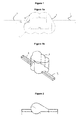
Fig. 1 shows a first embodiment of a device for separating bubbles from a fluid according to the invention. To carry out the experimental study polycarbonate chips with various chamber geometries were fabricated by milling. The chips consist of two half shells, which are both structured as due to the height of the cartridge as half shells from 2 mm, furthermore the chamber is divided between the two half-shells. -
Fig. 1a shows a plan view of achamber 1 and anafferent conduit 2 and anefferent conduit 3, whereasFig. 1b shows a perspective view of thechamber 1 and theafferent conduit 2 and theefferent conduit 3. The width of the afferent and theefferent conduit Fig. 1 to 4 is 0.5 mm. - A ramp at the inlet and outlet of the chamber can be added, so that no liquid remains standing in this chamber. Behind each chamber is a pentagonal viewing chamber which has a volume of 10 µl. The viewing chamber is laid out flat with a height of 1 mm, so that the bubbles, forwarded from the chamber, lie approximately in a plane, and can be well observed.
- For the variation of the device mainly the radii of the circular shapes are changed. This is accompanied by a change in size of the entire chamber which has the overall shape of cloud with respect to a plan view. Furthermore, two different forms of the side walls are being tested at input and output (respectively afferent and efferent conduit) of the structure. Table 1 gives an overview of possible geometries. Here, R is the radius of the circular shapes, d1 and d2 are the distance between the center of one circular shape to the center of the conduit, d3 and d4 are the distance between the center of one circular shape to another circular shape, both lying on the same axis, alpha1 (α1) and alpha2 (α2), and I1 and I2 are the dimensions of the splines, which lead to two different forms of the side walls.
Table 1: Examples for possible geometries of the first embodiment Example R [mm] d1 [mm] d2 [mm] d3 [mm] d4 [mm] alpha1 [°] alpha2 [°] I1 [mm] I2 [mm] 1 0.7 0.6 0.7 1.0 1.0 60 50 1.0 1.5 2 0.9 0.4 0.5 1.0 1.0 60 50 1.0 1.5 3 0.8 0.9 1.0 1.5 1.5 60 50 1.0 1.5 4 1.0 0.7 0.8 1.5 1.5 60 50 1.0 1.5 5 1.2 0.5 0.6 1.5 1.5 60 50 1.0 1.5 6 1.4 0.3 0.4 1.5 1.5 60 50 1.0 1.5 7 0.7 0.6 0.7 1.0 1.0 90 50 1.0 1.5 8 0.9 0.4 0.5 1.0 1.0 90 50 1.0 1.5 9 0.8 0.9 1.0 1.5 1.5 90 50 1.0 1.5 10 1.0 0.7 0.8 1.5 1.5 90 50 1.0 1.5 11 1.2 0.5 0.6 1.5 1.5 90 50 1.0 1.5 12 1.4 0.3 0.4 1.5 1.5 90 50 1.0 1.5 - Chip half shells were joined by Silpuran 4200, wherein Silpuran is a registered trademark and refers to silicone rubber compounds. The devices of the first embodiment are open upward so that the lyophilizates can be introduced here. In the experiments, each device was loaded with two lyophilizates. One of the beads contains the primer and the other all the remaining reagents. The lyophilized compositions comprise the following components:
No. Component 1 Buffer 2 Salt 3 Albumine 4 dNTPs 5 Primer 6 Probes 7 Polymerase 8 Matrix forming agent - The conduit structure is at the bottom of the structured polycarbonate plate and is sealed with double-sided PCR sheet and an unstructured plate. The chip is here contacted with a silicone conduit having an inner diameter of 2.1 mm and an outer diameter of 4 mm. For the experimental procedure, the peristaltic pump "Peristaltic Pump P-1" from Pharmacia Fine Chemicals was used. With the Peristaltic Pump P-1 flow velocities of about 1 ml / h to approximately 500 ml / h depending on the choice of the conduit inside diameter can be obtained, the pumping speed is infinitely adjustable. The conduit structure was observed with a microscope at a magnification of 2 to 4. For the dissolution of the various lyophilizates the following experimental parameters were chosen:
Solvent: HPLC-water Volume of solvent: 20 µl Pumpingrate: 2.6 µl/s - HPLC water was used as solvent because this is usually used when preparing reagents in biochemistry.
- It can be noted that with increasing chamber size the flow through of the device of the first embodiment according to the invention increased in height on the one hand and on the other hand an increased potential for chaotic flow was observed.
-
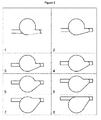
Fig. 2 andFig. 3 show a second embodiment of a device for separating bubbles from a fluid according to the invention. In a plan view the device of the second embodiment according to the invention is a circular shape with a diameter of 2.5 mm and a conduit with a cross sectional diameter of 0.7 mm which intersects the circular shape tangential. Thereafter, the conduit is shifted by 0.25 mm upwards and the circular shape is connected with the lower contour of the conduit tangentially, so that a nozzle is formed. This procedure is provided ingeometry 1 ofFig. 3 . For the second geometry, the conduit is again shifted upwards by 0.25 mm. Because the tip of the nozzle is fixed to the conduit, the angle of opening of the nozzle will also change. This scheme is continued untilgeometry 8 ofFig. 3 . The basic idea of this strategy is that it is predominantly the nozzle which causes the gas bubbles-retaining effect in the second embodiment of a device according to the invention. The further experiments were carried out in the same manner as described above - As a result, it can be stated that the first chamber geometry shows a pronounced region with a low flow velocity above the curve. Due to the migration of the conduit toward the chamber center, these low flow velocities get smaller and do no longer occur at the fifth geometry. The chamber is flowed through increasingly more evenly. In the first chamber geometry a vortex in the rounding of the second embodiment of a device according to the invention is formed and the chamber is completely flowed through in height. In the third and fourth geometry these vortexes no longer occur and the chamber is no longer flowed through in the upper quarter. Additionally it can be observed starting from the fifth chamber geometry that the chamber is increasingly less flowed through in its width. In the evaluation of the experiment, it was found that all the chamber geometries retained the gas bubbles similar effectively.
-
Fig. 4 shows the first and the second embodiment of a device according to the invention arranged in a lap-on-a-chip system. The chambers according to the first and second embodiment of a device according to the invention are located directly before the PCR chamber. The gas bubbles retaining effect of the first and second embodiment is used for an optimal carrying out of the PCR. Since the chambers of the invention separate the gas bubbles from the effusing fluid, no bubbles enter the PCR chamber. Thus, an optimal functioning of the PCR is guaranteed.
Claims (18)
- A device for separating bubbles from a fluid comprising a chamber (1), an afferent conduit (2) and an efferent conduit (3) guiding a fluid through said chamber (1), characterized in that the inner chamber wall has a geometry that generates within said chamber (1) a continuous flow and at least one area with a discontinuous flow, so that in the area of the discontinuous flow bubbles remain at the inner chamber wall and thus are separated from the fluid effusing from the chamber (1).
- The device according to claim 1, characterized in that the flow within the chamber generates areas of distinct flow velocities encompassing at least one area with a high flow velocity and at least one area with a low flow velocity, whereas the ratio of the flow velocity of the high flow velocity and the low flow velocity is at least 2:1.
- The device according to one of the above claims, characterized in, that the area of high flow velocity and the at least one area with a low flow velocity are adjacent to each other.
- The device according to claim 3, characterized in that the high flow velocity is at least 5 mm/s, preferably at least 10 mm/s and most preferably at least 20 mm/s.
- The device according to claim 3 or 4, characterized that the low flow velocity is not more than 5 mm/s, preferably not more than 1 mm/s and most preferably not more than 0.5 mm/s.
- The device according to one of the above claims, characterized in that the discontinuous flow comprises a chaotic flow or turbulences.
- The device according to one of the above claims, characterized in that the discontinuous flow comprises at least one region of dead water.
- The device according to one of the above claims, characterized in that the chamber comprises in a plan view at least one circular shape, wherein the at least one circular shape has a radius from 0.5 to 2 mm.
- The device according to one of the above claims, characterized in that the inner wall of the chamber, starting from the afferent conduit, has at least one convex bulge.
- The device according to one of the above claims, characterized in that the chamber comprises in a three-dimensional view at least one section which is based on non-linear bodies.
- The device according to one of the above claims, characterized in that the ratio of the chamber diameter to channel diameter in a cross sectional view perpendicular to the continuous flow is at least 4:1, more preferably at least 5:1, more preferably at least 6:1 and most preferably at least 7:1.
- The device according to one of the above claims, characterized in that a difference in velocity Δv is obtained in a distance Δx which leads to a ratio of the difference of velocity and the difference of distance Δv/Δx is in the region between 10 mms-1 / mm and 20 mms-1 / mm.
- The device according to one of the above claims, characterized in that the chamber contains a lyophilizate.
- The device according to one of the above claims, characterized in that the chamber is part of a lab-on-a-chip system.
- The device according to one of the above claims, characterized in that the device is a disposable.
- Use of a chamber for separating bubbles from a fluid, characterized in that the inner chamber wall has a geometry that generates within said chamber a continuous flow and at least one area with a discontinuous flow, so that in the area of the discontinuous flow bubbles remain at the inner chamber wall and thus are separated from the fluid effusing from the chamber.
- A fluidic, in particular microfluidic, system comprising a chamber, an afferent conduit and an efferent conduit guiding a fluid through said chamber, characterized in that the inner chamber wall has a geometry that generates within said chamber a continuous flow and at least one area with a discontinuous flow, so that in the area of the discontinuous flow bubbles remain at the inner chamber wall and thus are separated from the fluid effusing from the chamber.
- Method for separating bubbles from a fluidic sample, comprising the following steps:a) transferring the fluidic sample through a bubble trap which is connected to an analyzing device,b) forming a continuous flow and at least one area with a discontinuous flow of the sample in the bubble trap,c) retaining bubbles from the sample flowing out the bubble trap by absorbing the bubbles at the inner wall of the bubble trap in the area of the discontinuous flow.
Priority Applications (7)
| Application Number | Priority Date | Filing Date | Title |
|---|---|---|---|
| EP14181200.8A EP2985063A1 (en) | 2014-08-15 | 2014-08-15 | Device for separating bubbles from a fluid |
| EP15757133.2A EP3180099A1 (en) | 2014-08-15 | 2015-08-14 | Device for separating bubbles from a fluid |
| CA2957824A CA2957824A1 (en) | 2014-08-15 | 2015-08-14 | Device for separating bubbles from a fluid |
| JP2017508526A JP2017523435A (en) | 2014-08-15 | 2015-08-14 | Device for separating bubbles from a fluid |
| US15/503,821 US20170274379A1 (en) | 2014-08-15 | 2015-08-14 | Device for separating bubbles from a fluid |
| PCT/EP2015/001681 WO2016023637A1 (en) | 2014-08-15 | 2015-08-14 | Device for separating bubbles from a fluid |
| CN201580043850.2A CN106794396A (en) | 2014-08-15 | 2015-08-14 | Device for separating bubble from fluid |
Applications Claiming Priority (1)
| Application Number | Priority Date | Filing Date | Title |
|---|---|---|---|
| EP14181200.8A EP2985063A1 (en) | 2014-08-15 | 2014-08-15 | Device for separating bubbles from a fluid |
Publications (1)
| Publication Number | Publication Date |
|---|---|
| EP2985063A1 true EP2985063A1 (en) | 2016-02-17 |
Family
ID=51352449
Family Applications (2)
| Application Number | Title | Priority Date | Filing Date |
|---|---|---|---|
| EP14181200.8A Withdrawn EP2985063A1 (en) | 2014-08-15 | 2014-08-15 | Device for separating bubbles from a fluid |
| EP15757133.2A Withdrawn EP3180099A1 (en) | 2014-08-15 | 2015-08-14 | Device for separating bubbles from a fluid |
Family Applications After (1)
| Application Number | Title | Priority Date | Filing Date |
|---|---|---|---|
| EP15757133.2A Withdrawn EP3180099A1 (en) | 2014-08-15 | 2015-08-14 | Device for separating bubbles from a fluid |
Country Status (6)
| Country | Link |
|---|---|
| US (1) | US20170274379A1 (en) |
| EP (2) | EP2985063A1 (en) |
| JP (1) | JP2017523435A (en) |
| CN (1) | CN106794396A (en) |
| CA (1) | CA2957824A1 (en) |
| WO (1) | WO2016023637A1 (en) |
Cited By (3)
| Publication number | Priority date | Publication date | Assignee | Title |
|---|---|---|---|---|
| GB2555892A (en) * | 2016-07-12 | 2018-05-16 | Emulate Inc | Removing bubbles in a microfluidic device |
| EP3461557A1 (en) * | 2017-09-29 | 2019-04-03 | Sysmex Corporation | Cartridge, detection method, and detection device |
| US11596944B2 (en) | 2017-10-16 | 2023-03-07 | Quantumdx Group Limited | Microfluidic devices with bubble diversion |
Families Citing this family (6)
| Publication number | Priority date | Publication date | Assignee | Title |
|---|---|---|---|---|
| CN113730789A (en) | 2016-12-16 | 2021-12-03 | 索伦托治疗有限公司 | Fluid delivery device with suction mechanism and method of use |
| USD819197S1 (en) | 2016-12-16 | 2018-05-29 | Kimberly-Clark Worldwide, Inc. | Fluid delivery apparatus |
| USD836774S1 (en) | 2016-12-16 | 2018-12-25 | Sorrento Therapeutics, Inc. | Cartridge for a fluid delivery apparatus |
| CA3133974C (en) | 2019-03-18 | 2023-10-03 | Siemens Healthcare Diagnostics Inc. | Apparatus and methods for bubble traps in fluidic devices |
| DE102019003135A1 (en) * | 2019-05-03 | 2020-11-05 | Innome Gmbh | Microtiter plate |
| CN114514422A (en) | 2019-10-01 | 2022-05-17 | 基础科学公司 | Automated online preparation and degassing of volatile samples for online analysis |
Citations (6)
| Publication number | Priority date | Publication date | Assignee | Title |
|---|---|---|---|---|
| US6537356B1 (en) * | 1999-08-06 | 2003-03-25 | Nathaniel M. Soriano | Gas and solid trap for an intravenous line |
| US20050000364A1 (en) * | 2001-08-18 | 2005-01-06 | Peter Kraemer | Device for extracting gas or liquid from microfluidid through-flow systems |
| US7279031B1 (en) * | 2003-11-25 | 2007-10-09 | Wright David W | Emboli elimination apparatus |
| EP1855114A1 (en) | 2005-03-01 | 2007-11-14 | Rohm Co., Ltd. | Microchannel and microfluid chip |
| US20090126568A1 (en) * | 2007-11-15 | 2009-05-21 | Hideyuki Karaki | Method for removing intra-microchannel bubbles and intra-microchannel dissolving and dispersing method |
| US20100218679A1 (en) * | 2007-10-13 | 2010-09-02 | Neema Hekmat | Open lumen air filtration for liquid lines |
Family Cites Families (4)
| Publication number | Priority date | Publication date | Assignee | Title |
|---|---|---|---|---|
| US6802331B2 (en) * | 2002-03-28 | 2004-10-12 | Eksigent Technologies Llc | Particle-based check valve |
| GB2466644B (en) * | 2008-12-30 | 2011-05-11 | Biosurfit Sa | Liquid handling |
| EP2515975A1 (en) * | 2009-12-22 | 2012-10-31 | Cork Institute Of Technology | A bubble entrapment device |
| JP5529671B2 (en) * | 2010-08-10 | 2014-06-25 | セイコーインスツル株式会社 | Microfluidic device |
-
2014
- 2014-08-15 EP EP14181200.8A patent/EP2985063A1/en not_active Withdrawn
-
2015
- 2015-08-14 CA CA2957824A patent/CA2957824A1/en not_active Abandoned
- 2015-08-14 WO PCT/EP2015/001681 patent/WO2016023637A1/en active Application Filing
- 2015-08-14 EP EP15757133.2A patent/EP3180099A1/en not_active Withdrawn
- 2015-08-14 CN CN201580043850.2A patent/CN106794396A/en active Pending
- 2015-08-14 JP JP2017508526A patent/JP2017523435A/en active Pending
- 2015-08-14 US US15/503,821 patent/US20170274379A1/en not_active Abandoned
Patent Citations (6)
| Publication number | Priority date | Publication date | Assignee | Title |
|---|---|---|---|---|
| US6537356B1 (en) * | 1999-08-06 | 2003-03-25 | Nathaniel M. Soriano | Gas and solid trap for an intravenous line |
| US20050000364A1 (en) * | 2001-08-18 | 2005-01-06 | Peter Kraemer | Device for extracting gas or liquid from microfluidid through-flow systems |
| US7279031B1 (en) * | 2003-11-25 | 2007-10-09 | Wright David W | Emboli elimination apparatus |
| EP1855114A1 (en) | 2005-03-01 | 2007-11-14 | Rohm Co., Ltd. | Microchannel and microfluid chip |
| US20100218679A1 (en) * | 2007-10-13 | 2010-09-02 | Neema Hekmat | Open lumen air filtration for liquid lines |
| US20090126568A1 (en) * | 2007-11-15 | 2009-05-21 | Hideyuki Karaki | Method for removing intra-microchannel bubbles and intra-microchannel dissolving and dispersing method |
Cited By (11)
| Publication number | Priority date | Publication date | Assignee | Title |
|---|---|---|---|---|
| GB2555892A (en) * | 2016-07-12 | 2018-05-16 | Emulate Inc | Removing bubbles in a microfluidic device |
| US10335788B2 (en) | 2016-07-12 | 2019-07-02 | EMULATE, Inc. | Removing bubbles in a microfluidic device |
| US10661275B2 (en) | 2016-07-12 | 2020-05-26 | EMULATE, Inc. | Removing bubbles in a microfluidic device |
| US10913063B2 (en) | 2016-07-12 | 2021-02-09 | EMULATE, Inc. | Removing bubbles in a microfluidic device |
| GB2555892B (en) * | 2016-07-12 | 2021-03-31 | Emulate Inc | Removing bubbles in a microfluidic device |
| US10974242B2 (en) | 2016-07-12 | 2021-04-13 | EMULATE, Inc. | Removing bubbles in a microfluidic device |
| US11065620B2 (en) | 2016-07-12 | 2021-07-20 | EMULATE, Inc. | Removing bubbles in a microfluidic device |
| US11141727B2 (en) | 2016-07-12 | 2021-10-12 | EMULATE, Inc. | Removing bubbles in a microfluidic device |
| EP3461557A1 (en) * | 2017-09-29 | 2019-04-03 | Sysmex Corporation | Cartridge, detection method, and detection device |
| US11511246B2 (en) | 2017-09-29 | 2022-11-29 | Sysmex Corporation | Cartridge, detection method, and detection device |
| US11596944B2 (en) | 2017-10-16 | 2023-03-07 | Quantumdx Group Limited | Microfluidic devices with bubble diversion |
Also Published As
| Publication number | Publication date |
|---|---|
| CN106794396A (en) | 2017-05-31 |
| WO2016023637A1 (en) | 2016-02-18 |
| JP2017523435A (en) | 2017-08-17 |
| EP3180099A1 (en) | 2017-06-21 |
| CA2957824A1 (en) | 2016-02-18 |
| US20170274379A1 (en) | 2017-09-28 |
Similar Documents
| Publication | Publication Date | Title |
|---|---|---|
| EP2985063A1 (en) | Device for separating bubbles from a fluid | |
| Narayanamurthy et al. | Advances in passively driven microfluidics and lab-on-chip devices: A comprehensive literature review and patent analysis | |
| US6669831B2 (en) | Microfluidic devices and methods to regulate hydrodynamic and electrical resistance utilizing bulk viscosity enhancers | |
| US9744513B2 (en) | Encapsulation microfluidic device | |
| EP1855114A1 (en) | Microchannel and microfluid chip | |
| AU2001261541A1 (en) | Microfluidic devices and methods to regulate hydrodynamic and electrical resistance utilizing bulk viscosity enhancers | |
| JP4927817B2 (en) | Microfluidic device with multiple valves | |
| EP1525916A1 (en) | Flow triggering device | |
| JP2005177749A (en) | Microtiter plate for processing sample, system and method | |
| RU2525425C2 (en) | Gas-free chamber for fluid media | |
| JP2014525569A (en) | Method and system for a pre-programmed self-output microfluidic circuit | |
| JP6965526B2 (en) | Solution mixing method in microfluidic equipment, microfluidic equipment system and microfluidic equipment | |
| Qi et al. | Probing single cells using flow in microfluidic devices | |
| JP7198813B2 (en) | Microfluidic device with bubble diversion region | |
| JP5139264B2 (en) | Microfluidic device with finger valve | |
| WO2018100421A1 (en) | Methods for mixing fluids in microfluidic devices, and devices and systems therefor | |
| US20210031195A1 (en) | Fluidic device | |
| JP7226444B2 (en) | fluidic devices and systems | |
| Kim et al. | Sheathless microfluidic particle focusing technique using slanted microstructure array | |
| US11458467B2 (en) | Structures to define flow confinement shape and confinement stability with uniform aspiration | |
| KR101337587B1 (en) | A fluidic interconnection for lateral injection of microparticle and microparticle injection method using the same | |
| EP1525919A1 (en) | Flow triggering device | |
| US11130125B2 (en) | Prevention and bubble removal from microfluidic devices | |
| CN112691709B (en) | Fluid driving device, preparation method of fluid driving device and surface treatment method | |
| JP2019211254A (en) | cartridge |
Legal Events
| Date | Code | Title | Description |
|---|---|---|---|
| PUAI | Public reference made under article 153(3) epc to a published international application that has entered the european phase |
Free format text: ORIGINAL CODE: 0009012 |
|
| AK | Designated contracting states |
Kind code of ref document: A1 Designated state(s): AL AT BE BG CH CY CZ DE DK EE ES FI FR GB GR HR HU IE IS IT LI LT LU LV MC MK MT NL NO PL PT RO RS SE SI SK SM TR |
|
| AX | Request for extension of the european patent |
Extension state: BA ME |
|
| 17P | Request for examination filed |
Effective date: 20160817 |
|
| RBV | Designated contracting states (corrected) |
Designated state(s): AL AT BE BG CH CY CZ DE DK EE ES FI FR GB GR HR HU IE IS IT LI LT LU LV MC MK MT NL NO PL PT RO RS SE SI SK SM TR |
|
| RAP1 | Party data changed (applicant data changed or rights of an application transferred) |
Owner name: CURETIS GMBH |
|
| 17Q | First examination report despatched |
Effective date: 20170406 |
|
| STAA | Information on the status of an ep patent application or granted ep patent |
Free format text: STATUS: THE APPLICATION IS DEEMED TO BE WITHDRAWN |
|
| 18D | Application deemed to be withdrawn |
Effective date: 20170817 |