EP3461538A1 - Flame arrestor with fluid drainage capabilities - Google Patents
Flame arrestor with fluid drainage capabilities Download PDFInfo
- Publication number
- EP3461538A1 EP3461538A1 EP18197194.6A EP18197194A EP3461538A1 EP 3461538 A1 EP3461538 A1 EP 3461538A1 EP 18197194 A EP18197194 A EP 18197194A EP 3461538 A1 EP3461538 A1 EP 3461538A1
- Authority
- EP
- European Patent Office
- Prior art keywords
- module
- flame arrestor
- labyrinth channel
- fluid outlet
- fluid inlet
- Prior art date
- Legal status (The legal status is an assumption and is not a legal conclusion. Google has not performed a legal analysis and makes no representation as to the accuracy of the status listed.)
- Granted
Links
Images


Classifications
-
- A—HUMAN NECESSITIES
- A62—LIFE-SAVING; FIRE-FIGHTING
- A62C—FIRE-FIGHTING
- A62C4/00—Flame traps allowing passage of gas but not of flame or explosion wave
-
- F—MECHANICAL ENGINEERING; LIGHTING; HEATING; WEAPONS; BLASTING
- F23—COMBUSTION APPARATUS; COMBUSTION PROCESSES
- F23D—BURNERS
- F23D14/00—Burners for combustion of a gas, e.g. of a gas stored under pressure as a liquid
- F23D14/46—Details
- F23D14/72—Safety devices, e.g. operative in case of failure of gas supply
- F23D14/725—Protection against flame failure by using flame detection devices
-
- F—MECHANICAL ENGINEERING; LIGHTING; HEATING; WEAPONS; BLASTING
- F23—COMBUSTION APPARATUS; COMBUSTION PROCESSES
- F23D—BURNERS
- F23D14/00—Burners for combustion of a gas, e.g. of a gas stored under pressure as a liquid
- F23D14/46—Details
- F23D14/72—Safety devices, e.g. operative in case of failure of gas supply
- F23D14/74—Preventing flame lift-off
-
- F—MECHANICAL ENGINEERING; LIGHTING; HEATING; WEAPONS; BLASTING
- F23—COMBUSTION APPARATUS; COMBUSTION PROCESSES
- F23D—BURNERS
- F23D14/00—Burners for combustion of a gas, e.g. of a gas stored under pressure as a liquid
- F23D14/46—Details
- F23D14/72—Safety devices, e.g. operative in case of failure of gas supply
- F23D14/82—Preventing flashback or blowback
-
- F—MECHANICAL ENGINEERING; LIGHTING; HEATING; WEAPONS; BLASTING
- F05—INDEXING SCHEMES RELATING TO ENGINES OR PUMPS IN VARIOUS SUBCLASSES OF CLASSES F01-F04
- F05D—INDEXING SCHEME FOR ASPECTS RELATING TO NON-POSITIVE-DISPLACEMENT MACHINES OR ENGINES, GAS-TURBINES OR JET-PROPULSION PLANTS
- F05D2260/00—Function
- F05D2260/60—Fluid transfer
- F05D2260/602—Drainage
Definitions
- Flame arrestors are commonly used in aerospace and other industries to prevent detonations and/or deflagrations from exiting an enclosure through a vent line or other opening to the external environment.
- the arresting components-mesh, corrugations, or other barriers-must remain permeable to gases and vapors to permit proper venting.
- some aircraft systems, such as fuel and electronics systems must also have drainage ports for condensation that can accumulate in contained spaces. Thus, the need exists for a flame arrestor that is permeable to both gases and liquids, while still meeting flame suppression requirements
- a vented module includes a housing portion having a drainage side and a drainage port within the drainage side.
- the module further includes a flame arrestor including a first surface having a fluid inlet, a second surface having at least one fluid outlet, a labyrinth channel extending from the fluid inlet to the at least one fluid outlet, and at least one mesh screen disposed within the labyrinth channel.
- the flame arrestor is attached to the housing portion such that the drainage port is aligned with the fluid inlet.
- a method of providing flame suppression for a vented module includes forming a flame arrestor having a fluid inlet and a fluid outlet, and extending a labyrinth channel between the fluid inlet and the fluid outlet. The method further includes aligning the fluid inlet with a drainage port of a housing, and attaching the flame arrestor to the housing.
- the present invention is directed to a vented structure having a flame arrestor mounted thereto.
- the structure includes a housing having a drainage port, and the flame arrestor includes a fluid inlet that is aligned with the drainage port.
- a labyrinth-like channel within the flame arrestor extends from the fluid inlet to one or more fluid outlets.
- the flame arrestor also includes a mesh screen disposed within the labyrinth channel. The labyrinth channel and mesh are designed to allow condensation from within the larger structure to pass through the flame arrestor.
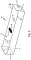
- FIG. 1 is a perspective view of flame arrestor 10, configured for attachment to a housing (shown in FIG. 2 ).
- Flame arrestor 10 includes mating surface 12, bottom surface 14, and sides 16 generally orthogonal to both mating and bottom surfaces 12 and 14, respectively.
- Mating surface 12 includes fluid inlet 18 and openings 20, through which screws or other fasteners can be passed.
- Mesh screen 22 is attached to flame arrestor 10 at inlet 18.
- Flame arrestor 10 also includes fluid outlets 24, two of which are shown in FIG. 1 in opposing sides 16. In other embodiments, flame arrestor 10 can include just one, two, or more than two outlets 24 in any of the sides 16, or bottom surface 14.
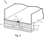
- FIG. 2 is a perspective cross-section showing flame arrestor 10 attached to housing 26 to form module 28.
- Housing 26 can belong to, for example, a differential pressure transducer, or any other system in which condensation or other fluids might collect and require draining.
- Housing 26 includes drainage port 32 extending through drainage side 30.
- Arrestor 10 further includes channel 34 extending from inlet 18 to outlets 24.
- Channel 34 includes an inner surface 36 that is generally smooth.
- channel 34 has a generally T-shaped cross-section, such that the fluid flow path requires a 90° turn to reach either outlet 24.
- Other cross-sectional shapes and flow path angles are contemplated herein.
- the combination of mesh screen(s) 22 and the configuration of channel 34 helps inhibit flame propagation through module 28 by affecting the kinetics of combustion (e.g. temperature and pressure).
- Sources of a potential combustion within module 28 can include, for example, fuel vapors from nearby fuel lines, or other combustible fluids, depending on the location of module 28.
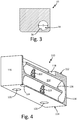
- FIG. 3 is an enlarged cross-section of flame arrestor 10, taken along line 3 of FIG. 1 .
- channel 34 has a circular cross-section, and a diameter D.
- Other cross-sectional shapes of channel 34 are contemplated herein.
- the ratio of the length to the diameter of channel 34 is at least 10:1.
- FIG. 4 is a perspective cross-section of alternative flame arrestor 110.
- arrestor 110 includes mating surface 112, bottom surface 114, and sides 116 generally orthogonal to mating and bottom surfaces 112 and 114.
- Mating surface 112 includes fluid inlet 118 and openings 120.
- channel 134 has a serpentine shape and multiple mesh screens 122 disposed within it.
- Arrestor 110 can also include only a single mesh screen 122 at any location along channel 134 (including at inlet 118), or it can include more than two mesh screens 122, depending on the fluid drainage and flame suppression requirements.
- a single fluid outlet 124 is located within bottom surface 114.
- other embodiments of arrestor 110 can include one or more fluid outlets 124 in any of bottom surface 114 or sides 116.
- Channel 134 includes an inner surface 136, which can include smooth and/or roughened portions.
- FIG. 5 is a perspective cross-section of flame arrestor 110 in which inner surface 136 of channel 134 includes ribs 138.
- Other types of disruptive surface features designed to inhibit flame propagation, such as dimples, are contemplated herein.
- channel 134 has a circular cross-sectional shape. Other cross-sectional shapes, such as an ellipse or quadrilateral, are contemplated herein.
- Channel 134 also has a length L and a diameter D (not labeled in FIGS. 4 and 5 ). The ratio of length to diameter is ideally 10:1 or greater, but can be less depending on the application.
- the cross-sectional shape and/or diameter of channel 134 can vary from inlet 118 to outlet 124.
- an initially circular channel 134 FIG. 6A
- an elliptical channel 134 FIG. 6B
- Other combinations of varying shapes and/or diameters are contemplated herein.
- the disclosed flame arrestors can be formed using either traditional or additive manufacturing techniques.
- arrestor 10 can be formed using a machining process to create inlet 18, outlets 24, and channel 34.
- Mesh screen 22 can be press fit to inlet 18, or it can simply be sandwiched between arrestor 10 and housing 26.
- Arrestor 110 can be additively manufactured using a technique such as laser powder bed fusion, directed energy deposition, selective laser sintering, or other suitable additive technique.
- mesh screens 122 and/or ribs 138 can be built directly into channel 134.
- Channel 134 can also have a more complex design, with various curves, cross-sectional shapes, and surface features that cannot typically be achieved using traditional subtractive manufacturing methods.
- Flame arrestors 10, 110 can be formed from a metal, metal alloy, or other material suitable for flame suppression applications.
- Mesh screens 22, 122 can be formed from the same material as arrestors 10, 110, or a different metal/metal alloy.
- Mesh screens 22, 122 can also have a variety of aperture sizes, depending on the requirements of the specific arrestor. In embodiments including multiple mesh screens, aperture sizes can be uniform, or can vary from screen to screen.
- Flame arrestors 10, 110 can further be attached to housing 26 using fasteners, or using a metal-joining process such as welding or brazing. Other attachment techniques providing a reasonably tight fit are contemplated herein. Arrestors 10, 110 can also be integrally formed with the housing or other structure for which it is providing flame suppression, such that the arrestor and housing are a monolithic structure.
- the disclosed flame arrestors have many advantages. First, they can provide flame suppression while allowing proper fluid drainage within a given system. They can be individually tailored for attachment to a variety of housings or other structures. Additively manufactured embodiments specifically can include extensive combinations of features and enhancements. In addition to aerospace applications, the disclosed flame arrestors can be used in other transportation industries, as well as for chemical, refining, and power generation applications, to name a few, non-limiting examples.
- a vented module includes a housing portion having a drainage side and a drainage port within the drainage side.
- the module further includes a flame arrestor including a first surface having a fluid inlet, a second surface having at least one fluid outlet, a labyrinth channel extending from the fluid inlet to the fluid outlet, and at least one mesh screen disposed within the labyrinth channel.
- the flame arrestor is attached to the housing portion such that the drainage port is aligned with the fluid inlet.
- the module of the preceding paragraph can optionally include, additionally and/or alternatively, any one or more of the following features, configurations and/or additional components:
- the second surface is orthogonal to the first surface.
- the second surface is parallel to the first surface.
- the at least one fluid outlet includes a first fluid outlet and a second fluid outlet.
- the first fluid outlet and the second fluid outlet are transverse.
- the at least one mesh screen is disposed across the fluid inlet.
- the at least one mesh screen comprises a first mesh screen and a second mesh screen.
- the flame arrestor and the at least one mesh screen are formed from a metal or metal alloy.
- the labyrinth channel includes an inner surface, and ribs on the inner surface.
- the labyrinth channel has a length and a diameter, and the ratio of the length to the diameter is 10:1.
- a cross-sectional shape of the labyrinth channel is generally circular.
- a diameter or a cross-sectional shape of the labyrinth channel varies.
- the labyrinth channel is T-shaped.
- the labyrinth channel is serpentine-shaped.
- the flame arrestor and the housing unit comprise a monolithic structure.
- a method of providing flame suppression for a vented module includes forming a flame arrestor having a fluid inlet and a fluid outlet, and extending a labyrinth channel between the fluid inlet and the fluid outlet. The method further includes aligning the fluid inlet with a drainage port of a housing, and attaching the flame arrestor to the housing.
- the method of the preceding paragraph can optionally include, additionally and/or alternatively, any one or more of the following features, configurations and/or additional components:
- the method includes disposing a mesh screen within the labyrinth channel.
- the method includes forming ribs on an inner surface of the labyrinth channel.
- the method includes forming the flame arrestor using an additive manufacturing technique.
- Attaching the flame arrestor to the housing includes a fastening, welding, or brazing technique.
Landscapes
- Engineering & Computer Science (AREA)
- Chemical & Material Sciences (AREA)
- Combustion & Propulsion (AREA)
- Mechanical Engineering (AREA)
- General Engineering & Computer Science (AREA)
- Health & Medical Sciences (AREA)
- Public Health (AREA)
- Business, Economics & Management (AREA)
- Emergency Management (AREA)
- Structure Of Emergency Protection For Nuclear Reactors (AREA)
- Fire-Detection Mechanisms (AREA)
- Gas Burners (AREA)
Abstract
Description
- Flame arrestors are commonly used in aerospace and other industries to prevent detonations and/or deflagrations from exiting an enclosure through a vent line or other opening to the external environment. The arresting components-mesh, corrugations, or other barriers-must remain permeable to gases and vapors to permit proper venting. In addition to requiring flame suppression, some aircraft systems, such as fuel and electronics systems, must also have drainage ports for condensation that can accumulate in contained spaces. Thus, the need exists for a flame arrestor that is permeable to both gases and liquids, while still meeting flame suppression requirements
- A vented module includes a housing portion having a drainage side and a drainage port within the drainage side. The module further includes a flame arrestor including a first surface having a fluid inlet, a second surface having at least one fluid outlet, a labyrinth channel extending from the fluid inlet to the at least one fluid outlet, and at least one mesh screen disposed within the labyrinth channel. The flame arrestor is attached to the housing portion such that the drainage port is aligned with the fluid inlet.
- A method of providing flame suppression for a vented module includes forming a flame arrestor having a fluid inlet and a fluid outlet, and extending a labyrinth channel between the fluid inlet and the fluid outlet. The method further includes aligning the fluid inlet with a drainage port of a housing, and attaching the flame arrestor to the housing.
-
-
FIG. 1 is a perspective view of a flame arrestor. -
FIG. 2 is a perspective cross-section of a module including the flame arrestor ofFIG. 1 . -
FIG. 3 is a cross-section of the flame arrestor ofFIG. 1 . -
FIG. 4 is a perspective cross-section of a second alternative flame arrestor. -
FIG. 5 is a perspective cross-section of a third alternative flame arrestor. -
FIGS. 6A and 6B are cross-sections of a labyrinth channel near the fluid inlet and fluid outlet, respectively, of a fourth alternative flame arrestor. - The present invention is directed to a vented structure having a flame arrestor mounted thereto. The structure includes a housing having a drainage port, and the flame arrestor includes a fluid inlet that is aligned with the drainage port. A labyrinth-like channel within the flame arrestor extends from the fluid inlet to one or more fluid outlets. The flame arrestor also includes a mesh screen disposed within the labyrinth channel. The labyrinth channel and mesh are designed to allow condensation from within the larger structure to pass through the flame arrestor.
-
FIG. 1 is a perspective view offlame arrestor 10, configured for attachment to a housing (shown inFIG. 2 ).Flame arrestor 10 includesmating surface 12,bottom surface 14, andsides 16 generally orthogonal to both mating andbottom surfaces Mating surface 12 includesfluid inlet 18 andopenings 20, through which screws or other fasteners can be passed.Mesh screen 22 is attached toflame arrestor 10 atinlet 18.Flame arrestor 10 also includesfluid outlets 24, two of which are shown inFIG. 1 inopposing sides 16. In other embodiments,flame arrestor 10 can include just one, two, or more than twooutlets 24 in any of thesides 16, orbottom surface 14. -
FIG. 2 is a perspective cross-section showingflame arrestor 10 attached tohousing 26 to formmodule 28.Housing 26 can belong to, for example, a differential pressure transducer, or any other system in which condensation or other fluids might collect and require draining.Housing 26 includesdrainage port 32 extending throughdrainage side 30. Whenarrestor 10 is attached tohousing 26,mating surface 12abuts drainage side 30 ofhousing 26, such thatfluid inlet 18 is aligned withdrainage port 32.Arrestor 10 further includeschannel 34 extending frominlet 18 tooutlets 24. Channel 34 includes aninner surface 36 that is generally smooth. - In operation, condensation exits housing 26 via
drainage port 32, entersarrestor 10 throughinlet 18, and flows throughchannel 34 to anoutlet 24, as is shown by the arrows. In the view shown inFIG. 2 ,channel 34 has a generally T-shaped cross-section, such that the fluid flow path requires a 90° turn to reach eitheroutlet 24. Other cross-sectional shapes and flow path angles are contemplated herein. Although permeable to condensation and other fluids, the combination of mesh screen(s) 22 and the configuration ofchannel 34 helps inhibit flame propagation throughmodule 28 by affecting the kinetics of combustion (e.g. temperature and pressure). Sources of a potential combustion withinmodule 28 can include, for example, fuel vapors from nearby fuel lines, or other combustible fluids, depending on the location ofmodule 28. -
FIG. 3 is an enlarged cross-section offlame arrestor 10, taken alongline 3 ofFIG. 1 . As can be seen inFIG. 3 ,channel 34 has a circular cross-section, and a diameter D. Other cross-sectional shapes ofchannel 34 are contemplated herein. Ideally, the ratio of the length to the diameter ofchannel 34 is at least 10:1. -
FIG. 4 is a perspective cross-section ofalternative flame arrestor 110. In the embodiment shown,arrestor 110 includesmating surface 112,bottom surface 114, andsides 116 generally orthogonal to mating andbottom surfaces Mating surface 112 includesfluid inlet 118 andopenings 120. Unlike the configuration ofarrestor 10,channel 134 has a serpentine shape andmultiple mesh screens 122 disposed within it. Arrestor 110 can also include only asingle mesh screen 122 at any location along channel 134 (including at inlet 118), or it can include more than twomesh screens 122, depending on the fluid drainage and flame suppression requirements. Also unlikearrestor 10, asingle fluid outlet 124 is located withinbottom surface 114. However, other embodiments ofarrestor 110 can include one ormore fluid outlets 124 in any ofbottom surface 114 orsides 116. -
Channel 134 includes aninner surface 136, which can include smooth and/or roughened portions. For example,FIG. 5 is a perspective cross-section offlame arrestor 110 in whichinner surface 136 ofchannel 134 includesribs 138. Other types of disruptive surface features designed to inhibit flame propagation, such as dimples, are contemplated herein. - Like
channel 34,channel 134 has a circular cross-sectional shape. Other cross-sectional shapes, such as an ellipse or quadrilateral, are contemplated herein. Channel 134 also has a length L and a diameter D (not labeled inFIGS. 4 and5 ). The ratio of length to diameter is ideally 10:1 or greater, but can be less depending on the application. - In certain embodiments, the cross-sectional shape and/or diameter of
channel 134 can vary frominlet 118 tooutlet 124. For example, inFIGS. 6A and 6B , an initially circular channel 134 (FIG. 6A ) transitions to an elliptical channel 134 (FIG. 6B ) in a region nearoutlet 124. Other combinations of varying shapes and/or diameters are contemplated herein. - The disclosed flame arrestors can be formed using either traditional or additive manufacturing techniques. For example,
arrestor 10 can be formed using a machining process to createinlet 18,outlets 24, andchannel 34.Mesh screen 22 can be press fit toinlet 18, or it can simply be sandwiched betweenarrestor 10 andhousing 26.Arrestor 110 can be additively manufactured using a technique such as laser powder bed fusion, directed energy deposition, selective laser sintering, or other suitable additive technique. As such, mesh screens 122 and/orribs 138 can be built directly intochannel 134.Channel 134 can also have a more complex design, with various curves, cross-sectional shapes, and surface features that cannot typically be achieved using traditional subtractive manufacturing methods. -
Flame arrestors arrestors -
Flame arrestors housing 26 using fasteners, or using a metal-joining process such as welding or brazing. Other attachment techniques providing a reasonably tight fit are contemplated herein.Arrestors - The disclosed flame arrestors have many advantages. First, they can provide flame suppression while allowing proper fluid drainage within a given system. They can be individually tailored for attachment to a variety of housings or other structures. Additively manufactured embodiments specifically can include extensive combinations of features and enhancements. In addition to aerospace applications, the disclosed flame arrestors can be used in other transportation industries, as well as for chemical, refining, and power generation applications, to name a few, non-limiting examples.
- The following are non-exclusive descriptions of possible embodiments of the present invention.
- A vented module includes a housing portion having a drainage side and a drainage port within the drainage side. The module further includes a flame arrestor including a first surface having a fluid inlet, a second surface having at least one fluid outlet, a labyrinth channel extending from the fluid inlet to the fluid outlet, and at least one mesh screen disposed within the labyrinth channel. The flame arrestor is attached to the housing portion such that the drainage port is aligned with the fluid inlet.
- The module of the preceding paragraph can optionally include, additionally and/or alternatively, any one or more of the following features, configurations and/or additional components:
The second surface is orthogonal to the first surface. - The second surface is parallel to the first surface.
- The at least one fluid outlet includes a first fluid outlet and a second fluid outlet.
- The first fluid outlet and the second fluid outlet are transverse.
- The at least one mesh screen is disposed across the fluid inlet.
- The at least one mesh screen comprises a first mesh screen and a second mesh screen.
- The flame arrestor and the at least one mesh screen are formed from a metal or metal alloy.
- The labyrinth channel includes an inner surface, and ribs on the inner surface.
- The labyrinth channel has a length and a diameter, and the ratio of the length to the diameter is 10:1.
- A cross-sectional shape of the labyrinth channel is generally circular.
- A diameter or a cross-sectional shape of the labyrinth channel varies.
- The labyrinth channel is T-shaped.
- The labyrinth channel is serpentine-shaped.
- The flame arrestor and the housing unit comprise a monolithic structure.
- A method of providing flame suppression for a vented module includes forming a flame arrestor having a fluid inlet and a fluid outlet, and extending a labyrinth channel between the fluid inlet and the fluid outlet. The method further includes aligning the fluid inlet with a drainage port of a housing, and attaching the flame arrestor to the housing.
- The method of the preceding paragraph can optionally include, additionally and/or alternatively, any one or more of the following features, configurations and/or additional components:
The method includes disposing a mesh screen within the labyrinth channel. - The method includes forming ribs on an inner surface of the labyrinth channel.
- The method includes forming the flame arrestor using an additive manufacturing technique.
- Attaching the flame arrestor to the housing includes a fastening, welding, or brazing technique.
- While the invention has been described with reference to an exemplary embodiment(s), it will be understood by those skilled in the art that various changes may be made and equivalents may be substituted for elements thereof without departing from the scope of the invention. In addition, many modifications may be made to adapt a particular situation or material to the teachings of the invention without departing from the essential scope thereof. Therefore, it is intended that the invention not be limited to the particular embodiment(s) disclosed, but that the invention will include all embodiments falling within the scope of the appended claims.
Claims (15)
- A vented module comprising:a housing portion having a drainage side and a drainage port within the drainage side; anda flame arrestor comprising:a first surface having a fluid inlet;a second surface having at least one fluid outlet;a labyrinth channel extending from the fluid inlet to the at least one fluid outlet; andat least one mesh screen disposed within the labyrinth channel;wherein the flame arrestor is attached to the housing portion such that the drainage port is aligned with the fluid inlet.
- The module of claim 1, wherein the second surface is orthogonal to the first surface, or
wherein the second surface is parallel to the first surface. - The module of claim 1 or 2, wherein the at least one fluid outlet comprises a first fluid outlet and a second fluid outlet,
wherein, optionally, the first fluid outlet and the second fluid outlet are transverse. - The module of any preceding claim, wherein the at least one mesh screen is disposed across the fluid inlet.
- The module of any preceding claim, wherein the at least one mesh screen comprises a first mesh screen and a second mesh screen.
- The module of any preceding claim, wherein the flame arrestor and the at least one mesh screen are formed from a metal or a metal alloy.
- The module of any preceding claim, wherein the labyrinth channel comprises an inner surface, and wherein the inner surface includes ribs.
- The module of any preceding claim, wherein the labyrinth channel comprises a length and a diameter, and wherein the ratio of the length to the diameter is at least 10:1.
- The module of any preceding claim, wherein a diameter or a cross-sectional shape of the labyrinth channel varies.
- The module of any preceding claim, wherein the labyrinth channel is T-shaped, or wherein the labyrinth channel is serpentine-shaped.
- The module of any preceding claim, wherein the flame arrestor and the housing unit comprise a monolithic structure.
- A method of providing flame suppression for a vented module, the method comprising:forming a flame arrestor having a fluid inlet and a fluid outlet;extending a labyrinth channel between the fluid inlet and the fluid outlet;aligning the fluid inlet with a drainage port of a housing; andattaching the flame arrestor to the housing.
- The method of claim 12 and further comprising: disposing a mesh screen within the labyrinth channel.
- The method of claim 12 or 13 and further comprising: forming ribs on an inner surface of the labyrinth channel.
- The method of claim 12, 13 or 14, wherein attaching the flame arrestor to the housing comprises a fastening, welding, or brazing technique.
Applications Claiming Priority (1)
| Application Number | Priority Date | Filing Date | Title |
|---|---|---|---|
| US15/720,834 US11168883B2 (en) | 2017-09-29 | 2017-09-29 | Flame arrestor with fluid drainage capabilities |
Publications (2)
| Publication Number | Publication Date |
|---|---|
| EP3461538A1 true EP3461538A1 (en) | 2019-04-03 |
| EP3461538B1 EP3461538B1 (en) | 2020-11-11 |
Family
ID=63685881
Family Applications (1)
| Application Number | Title | Priority Date | Filing Date |
|---|---|---|---|
| EP18197194.6A Active EP3461538B1 (en) | 2017-09-29 | 2018-09-27 | Flame arrestor with fluid drainage capabilities |
Country Status (2)
| Country | Link |
|---|---|
| US (1) | US11168883B2 (en) |
| EP (1) | EP3461538B1 (en) |
Families Citing this family (2)
| Publication number | Priority date | Publication date | Assignee | Title |
|---|---|---|---|---|
| EP3882499B1 (en) | 2020-03-20 | 2023-03-15 | Goodrich Corporation | 3d printed maze in pressure regulating valve |
| US20220409937A1 (en) * | 2021-06-25 | 2022-12-29 | Essex Industries, Inc. | Flame arrestor |
Citations (3)
| Publication number | Priority date | Publication date | Assignee | Title |
|---|---|---|---|---|
| DE102010016782A1 (en) * | 2010-05-04 | 2011-11-10 | R.Stahl Schaltgeräte GmbH | Pressure relief device for flameproof enclosures |
| EP2844046A2 (en) * | 2013-08-27 | 2015-03-04 | R. Stahl Schaltgeräte GmbH | Housing part for a housing with flameproof encapsulation comprising a porous body |
| US20160305653A1 (en) * | 2015-04-17 | 2016-10-20 | Eaton Corporation | Flame arrestor |
Family Cites Families (43)
| Publication number | Priority date | Publication date | Assignee | Title |
|---|---|---|---|---|
| US258749A (en) * | 1882-05-30 | Protector for oil-tanks | ||
| US3394844A (en) * | 1966-08-05 | 1968-07-30 | Exxon Research Engineering Co | Vent valve for cryogenic cargo tanks |
| US4357051A (en) | 1980-06-02 | 1982-11-02 | Occidental Oil Shale, Inc. | Withdrawal of gases and liquids from an in situ oil shale retort |
| US4317868A (en) * | 1980-09-19 | 1982-03-02 | Gould Inc. | Battery vent plug with flame arrestor |
| DE3701027A1 (en) | 1987-01-16 | 1988-07-28 | Hans Otto Mieth | METHOD AND DEVICE FOR CONTROLLING A LEAKAGE SPACE OF A VALVE |
| US4997527A (en) | 1988-04-22 | 1991-03-05 | Kress Corporation | Coke handling and dry quenching method |
| US4870855A (en) | 1987-12-22 | 1989-10-03 | Delphian Corporation | Gas sensor protection devices and assemblies |
| US5045635A (en) | 1989-06-16 | 1991-09-03 | Schlegel Corporation | Conductive gasket with flame and abrasion resistant conductive coating |
| CN2050125U (en) | 1989-07-01 | 1989-12-27 | 北京化工学院 | Gas and liquid separating unit |
| CA2024083C (en) | 1990-08-27 | 2000-06-20 | Yoshio Asanuma | Positive displacement flowmeter |
| CN2147875Y (en) | 1992-12-04 | 1993-12-01 | 张选华 | Labyrinth sealed flame trap |
| US5284720A (en) | 1993-05-27 | 1994-02-08 | Globe-Union Inc. | Vent cap with electrolyte drain and explosion attenuation capabilities |
| BR9304238A (en) | 1993-10-15 | 1995-06-06 | Petroleo Brasileiro Sa | Thermo-chemical cleaning of storage tanks |
| US5841056A (en) | 1996-05-31 | 1998-11-24 | Hydrodyne Incorporated | Water deflector for water-gas plumes from underwater explosions |
| EP0961715A1 (en) | 1997-02-24 | 1999-12-08 | Raychem Corporation | Cavity sealing article and method |
| JP3920406B2 (en) | 1997-05-21 | 2007-05-30 | ヤマハ発動機株式会社 | Small ship |
| US20050120715A1 (en) | 1997-12-23 | 2005-06-09 | Christion School Of Technology Charitable Foundation Trust | Heat energy recapture and recycle and its new applications |
| US6372983B1 (en) | 1999-04-14 | 2002-04-16 | Ballard Generation Systems Inc. | Enclosure for electrical components installed in locations where a flammable gas or vapor is expected to be present |
| US20070020573A1 (en) | 1999-12-21 | 2007-01-25 | Furner Paul E | Candle assembly with light emitting system |
| CA2493557A1 (en) | 2002-07-24 | 2004-01-29 | Nippon Kayaku Kabushiki Kaisha | Waterproof granular explosive composition |
| US20040243462A1 (en) | 2003-05-29 | 2004-12-02 | Stier Randy S. | Method for benchmarking and scoring processes and equipment related practices and procedures |
| WO2007089246A2 (en) | 2005-02-09 | 2007-08-09 | Giraffe Liquid Management Systems, Inc. | Adjustable height inlet/outlet liquid level management tools and systems |
| JP4695441B2 (en) | 2005-06-07 | 2011-06-08 | 本田技研工業株式会社 | Gas sensor |
| EP1920045A4 (en) | 2005-08-11 | 2011-07-06 | Life Technologies Corp | Apparatus for assay, synthesis and storage, and methods of manufacture, use, and manipulation thereof |
| AU2007237177B2 (en) | 2006-02-15 | 2008-04-03 | John Noel Flint | An insert for a weep hole opening in a masonry wall |
| CA2597068A1 (en) | 2007-06-19 | 2008-12-19 | Peter Romaniuk | Hydrogen/oxygen gas produced by electrolysis as a partial hybrid fuel source for conventional internal combustion engines |
| JP5240897B2 (en) | 2007-12-19 | 2013-07-17 | 日立マクセル株式会社 | Alkaline battery |
| WO2011005895A1 (en) * | 2009-07-07 | 2011-01-13 | Firestar Engineering Llc | Aluminum porous media |
| CN101597563B (en) | 2009-07-13 | 2013-05-29 | 创东能源环保科技(福建)有限公司 | Waste landfill gas collection and generation equipment and method for constructing gas collection well |
| GB0918738D0 (en) | 2009-10-26 | 2009-12-09 | Compactgtl Plc | Reactor with channels |
| US10690340B2 (en) | 2010-01-06 | 2020-06-23 | Precision Combustion, Inc. | Flameless cooking appliance |
| CN203075801U (en) | 2012-12-18 | 2013-07-24 | 中国石油天然气股份有限公司 | Skid-mounted wellhead gas-liquid separation device |
| DE102013006738B4 (en) * | 2013-04-19 | 2014-12-31 | Peter Reitinger | Pressure relief device |
| CA2844711C (en) | 2014-03-05 | 2023-01-10 | University Of Saskatchewan | Degradation of hydrocarbons using filamentous fungus |
| DE102014007414B4 (en) * | 2014-05-22 | 2019-03-07 | Peter Reitinger | Pressure relief device |
| GB201417544D0 (en) * | 2014-10-03 | 2014-11-19 | Elmac Technologies Ltd | Flame arresters |
| DE102014116149A1 (en) * | 2014-11-06 | 2016-05-12 | R. Stahl Schaltgeräte GmbH | Flame-proofing filter of a number of layer sequences as well as arrangements of flameproof filters and their use |
| CN104953165B (en) | 2015-07-12 | 2017-05-31 | 东莞市盛利能源科技有限公司 | Overcharge explosion-proof lithium battery |
| CN204793058U (en) | 2015-07-12 | 2015-11-18 | 陈卡丹 | Cross and fill explosion -proof lithium cell |
| CN105271709B (en) | 2015-10-22 | 2019-03-15 | 南京航空航天大学 | A method for preparing two-component ultra-fine glass fiber wool by two-stage bushing kiln |
| DE102016000848B3 (en) * | 2016-01-28 | 2017-06-29 | Rexotec Ag | Pressure relief device |
| US9987508B2 (en) * | 2016-08-31 | 2018-06-05 | Emerson Process Management Regulator Technologies Tulsa, Llc | Hybrid composite flame cell |
| US20180056100A1 (en) * | 2016-08-31 | 2018-03-01 | Emerson Process Management Regulator Technologies Tulsa, Llc | Method for Manufacturing a Flame Arrestor |
-
2017
- 2017-09-29 US US15/720,834 patent/US11168883B2/en active Active
-
2018
- 2018-09-27 EP EP18197194.6A patent/EP3461538B1/en active Active
Patent Citations (3)
| Publication number | Priority date | Publication date | Assignee | Title |
|---|---|---|---|---|
| DE102010016782A1 (en) * | 2010-05-04 | 2011-11-10 | R.Stahl Schaltgeräte GmbH | Pressure relief device for flameproof enclosures |
| EP2844046A2 (en) * | 2013-08-27 | 2015-03-04 | R. Stahl Schaltgeräte GmbH | Housing part for a housing with flameproof encapsulation comprising a porous body |
| US20160305653A1 (en) * | 2015-04-17 | 2016-10-20 | Eaton Corporation | Flame arrestor |
Also Published As
| Publication number | Publication date |
|---|---|
| EP3461538B1 (en) | 2020-11-11 |
| US20190101284A1 (en) | 2019-04-04 |
| US11168883B2 (en) | 2021-11-09 |
Similar Documents
| Publication | Publication Date | Title |
|---|---|---|
| JP5984446B2 (en) | Turbine housing assembly and method of manufacturing turbine housing assembly | |
| EP2498877B1 (en) | Inline plug flame arrestors | |
| EP3461538B1 (en) | Flame arrestor with fluid drainage capabilities | |
| EP2853482B1 (en) | Drain mast | |
| US8961636B2 (en) | Oil separator | |
| CN101761378B (en) | X-tube and accompanying exhaust gas assembly | |
| CN114843665A (en) | Battery degassing unit and battery case | |
| JP2008235725A (en) | Water-cooled heat sink | |
| JP2013199864A (en) | Turbine housing assembly | |
| CN118622948B (en) | Ventilation plug, transmission and vehicle | |
| US20180280850A1 (en) | Breather | |
| EP3728807B1 (en) | End can assembly for an engine exhaust aftertreatment canister | |
| JPS62131929A (en) | Wall with cooling fluid channel | |
| JP2016156592A (en) | Heat exchanger | |
| EP2899463A1 (en) | Flame screen burner assembly | |
| EP3378781B1 (en) | Fume tight sock collector/box | |
| DE102020216462A1 (en) | drive unit | |
| US8298309B2 (en) | Liquid separator and tank system comprising a liquid separator | |
| US11319846B2 (en) | Oil separator | |
| JP6487652B2 (en) | Fluid equipment and fluid control equipment | |
| EP3885559B1 (en) | Exhaust baffle component for an air turbine starter assembly | |
| US20180073474A1 (en) | Air intake system for engine | |
| US6514323B1 (en) | Purification assemblies and purification methods | |
| GB2542944A (en) | Strainers | |
| EP3073076A1 (en) | Muffler |
Legal Events
| Date | Code | Title | Description |
|---|---|---|---|
| PUAI | Public reference made under article 153(3) epc to a published international application that has entered the european phase |
Free format text: ORIGINAL CODE: 0009012 |
|
| STAA | Information on the status of an ep patent application or granted ep patent |
Free format text: STATUS: THE APPLICATION HAS BEEN PUBLISHED |
|
| AK | Designated contracting states |
Kind code of ref document: A1 Designated state(s): AL AT BE BG CH CY CZ DE DK EE ES FI FR GB GR HR HU IE IS IT LI LT LU LV MC MK MT NL NO PL PT RO RS SE SI SK SM TR |
|
| AX | Request for extension of the european patent |
Extension state: BA ME |
|
| STAA | Information on the status of an ep patent application or granted ep patent |
Free format text: STATUS: REQUEST FOR EXAMINATION WAS MADE |
|
| STAA | Information on the status of an ep patent application or granted ep patent |
Free format text: STATUS: EXAMINATION IS IN PROGRESS |
|
| 17P | Request for examination filed |
Effective date: 20191002 |
|
| RBV | Designated contracting states (corrected) |
Designated state(s): AL AT BE BG CH CY CZ DE DK EE ES FI FR GB GR HR HU IE IS IT LI LT LU LV MC MK MT NL NO PL PT RO RS SE SI SK SM TR |
|
| 17Q | First examination report despatched |
Effective date: 20191022 |
|
| GRAP | Despatch of communication of intention to grant a patent |
Free format text: ORIGINAL CODE: EPIDOSNIGR1 |
|
| STAA | Information on the status of an ep patent application or granted ep patent |
Free format text: STATUS: GRANT OF PATENT IS INTENDED |
|
| INTG | Intention to grant announced |
Effective date: 20200703 |
|
| RIN1 | Information on inventor provided before grant (corrected) |
Inventor name: WESSER, AARON Inventor name: WIGEN, SCOTT Inventor name: SHERMAN, ANDREW Inventor name: BENNING, KEVIN |
|
| GRAS | Grant fee paid |
Free format text: ORIGINAL CODE: EPIDOSNIGR3 |
|
| GRAA | (expected) grant |
Free format text: ORIGINAL CODE: 0009210 |
|
| STAA | Information on the status of an ep patent application or granted ep patent |
Free format text: STATUS: THE PATENT HAS BEEN GRANTED |
|
| AK | Designated contracting states |
Kind code of ref document: B1 Designated state(s): AL AT BE BG CH CY CZ DE DK EE ES FI FR GB GR HR HU IE IS IT LI LT LU LV MC MK MT NL NO PL PT RO RS SE SI SK SM TR |
|
| REG | Reference to a national code |
Ref country code: GB Ref legal event code: FG4D |
|
| REG | Reference to a national code |
Ref country code: CH Ref legal event code: EP |
|
| REG | Reference to a national code |
Ref country code: AT Ref legal event code: REF Ref document number: 1332895 Country of ref document: AT Kind code of ref document: T Effective date: 20201115 |
|
| REG | Reference to a national code |
Ref country code: DE Ref legal event code: R096 Ref document number: 602018009601 Country of ref document: DE |
|
| REG | Reference to a national code |
Ref country code: IE Ref legal event code: FG4D |
|
| REG | Reference to a national code |
Ref country code: NL Ref legal event code: MP Effective date: 20201111 |
|
| REG | Reference to a national code |
Ref country code: AT Ref legal event code: MK05 Ref document number: 1332895 Country of ref document: AT Kind code of ref document: T Effective date: 20201111 |
|
| PG25 | Lapsed in a contracting state [announced via postgrant information from national office to epo] |
Ref country code: NO Free format text: LAPSE BECAUSE OF FAILURE TO SUBMIT A TRANSLATION OF THE DESCRIPTION OR TO PAY THE FEE WITHIN THE PRESCRIBED TIME-LIMIT Effective date: 20210211 Ref country code: GR Free format text: LAPSE BECAUSE OF FAILURE TO SUBMIT A TRANSLATION OF THE DESCRIPTION OR TO PAY THE FEE WITHIN THE PRESCRIBED TIME-LIMIT Effective date: 20210212 Ref country code: PT Free format text: LAPSE BECAUSE OF FAILURE TO SUBMIT A TRANSLATION OF THE DESCRIPTION OR TO PAY THE FEE WITHIN THE PRESCRIBED TIME-LIMIT Effective date: 20210311 Ref country code: RS Free format text: LAPSE BECAUSE OF FAILURE TO SUBMIT A TRANSLATION OF THE DESCRIPTION OR TO PAY THE FEE WITHIN THE PRESCRIBED TIME-LIMIT Effective date: 20201111 Ref country code: FI Free format text: LAPSE BECAUSE OF FAILURE TO SUBMIT A TRANSLATION OF THE DESCRIPTION OR TO PAY THE FEE WITHIN THE PRESCRIBED TIME-LIMIT Effective date: 20201111 |
|
| PG25 | Lapsed in a contracting state [announced via postgrant information from national office to epo] |
Ref country code: AT Free format text: LAPSE BECAUSE OF FAILURE TO SUBMIT A TRANSLATION OF THE DESCRIPTION OR TO PAY THE FEE WITHIN THE PRESCRIBED TIME-LIMIT Effective date: 20201111 Ref country code: PL Free format text: LAPSE BECAUSE OF FAILURE TO SUBMIT A TRANSLATION OF THE DESCRIPTION OR TO PAY THE FEE WITHIN THE PRESCRIBED TIME-LIMIT Effective date: 20201111 Ref country code: IS Free format text: LAPSE BECAUSE OF FAILURE TO SUBMIT A TRANSLATION OF THE DESCRIPTION OR TO PAY THE FEE WITHIN THE PRESCRIBED TIME-LIMIT Effective date: 20210311 Ref country code: LV Free format text: LAPSE BECAUSE OF FAILURE TO SUBMIT A TRANSLATION OF THE DESCRIPTION OR TO PAY THE FEE WITHIN THE PRESCRIBED TIME-LIMIT Effective date: 20201111 Ref country code: SE Free format text: LAPSE BECAUSE OF FAILURE TO SUBMIT A TRANSLATION OF THE DESCRIPTION OR TO PAY THE FEE WITHIN THE PRESCRIBED TIME-LIMIT Effective date: 20201111 Ref country code: BG Free format text: LAPSE BECAUSE OF FAILURE TO SUBMIT A TRANSLATION OF THE DESCRIPTION OR TO PAY THE FEE WITHIN THE PRESCRIBED TIME-LIMIT Effective date: 20210211 |
|
| REG | Reference to a national code |
Ref country code: LT Ref legal event code: MG9D |
|
| PG25 | Lapsed in a contracting state [announced via postgrant information from national office to epo] |
Ref country code: HR Free format text: LAPSE BECAUSE OF FAILURE TO SUBMIT A TRANSLATION OF THE DESCRIPTION OR TO PAY THE FEE WITHIN THE PRESCRIBED TIME-LIMIT Effective date: 20201111 |
|
| PG25 | Lapsed in a contracting state [announced via postgrant information from national office to epo] |
Ref country code: CZ Free format text: LAPSE BECAUSE OF FAILURE TO SUBMIT A TRANSLATION OF THE DESCRIPTION OR TO PAY THE FEE WITHIN THE PRESCRIBED TIME-LIMIT Effective date: 20201111 Ref country code: EE Free format text: LAPSE BECAUSE OF FAILURE TO SUBMIT A TRANSLATION OF THE DESCRIPTION OR TO PAY THE FEE WITHIN THE PRESCRIBED TIME-LIMIT Effective date: 20201111 Ref country code: SM Free format text: LAPSE BECAUSE OF FAILURE TO SUBMIT A TRANSLATION OF THE DESCRIPTION OR TO PAY THE FEE WITHIN THE PRESCRIBED TIME-LIMIT Effective date: 20201111 Ref country code: RO Free format text: LAPSE BECAUSE OF FAILURE TO SUBMIT A TRANSLATION OF THE DESCRIPTION OR TO PAY THE FEE WITHIN THE PRESCRIBED TIME-LIMIT Effective date: 20201111 Ref country code: SK Free format text: LAPSE BECAUSE OF FAILURE TO SUBMIT A TRANSLATION OF THE DESCRIPTION OR TO PAY THE FEE WITHIN THE PRESCRIBED TIME-LIMIT Effective date: 20201111 Ref country code: LT Free format text: LAPSE BECAUSE OF FAILURE TO SUBMIT A TRANSLATION OF THE DESCRIPTION OR TO PAY THE FEE WITHIN THE PRESCRIBED TIME-LIMIT Effective date: 20201111 |
|
| REG | Reference to a national code |
Ref country code: DE Ref legal event code: R097 Ref document number: 602018009601 Country of ref document: DE |
|
| PG25 | Lapsed in a contracting state [announced via postgrant information from national office to epo] |
Ref country code: DK Free format text: LAPSE BECAUSE OF FAILURE TO SUBMIT A TRANSLATION OF THE DESCRIPTION OR TO PAY THE FEE WITHIN THE PRESCRIBED TIME-LIMIT Effective date: 20201111 |
|
| PLBE | No opposition filed within time limit |
Free format text: ORIGINAL CODE: 0009261 |
|
| STAA | Information on the status of an ep patent application or granted ep patent |
Free format text: STATUS: NO OPPOSITION FILED WITHIN TIME LIMIT |
|
| 26N | No opposition filed |
Effective date: 20210812 |
|
| PG25 | Lapsed in a contracting state [announced via postgrant information from national office to epo] |
Ref country code: IT Free format text: LAPSE BECAUSE OF FAILURE TO SUBMIT A TRANSLATION OF THE DESCRIPTION OR TO PAY THE FEE WITHIN THE PRESCRIBED TIME-LIMIT Effective date: 20201111 Ref country code: AL Free format text: LAPSE BECAUSE OF FAILURE TO SUBMIT A TRANSLATION OF THE DESCRIPTION OR TO PAY THE FEE WITHIN THE PRESCRIBED TIME-LIMIT Effective date: 20201111 Ref country code: NL Free format text: LAPSE BECAUSE OF FAILURE TO SUBMIT A TRANSLATION OF THE DESCRIPTION OR TO PAY THE FEE WITHIN THE PRESCRIBED TIME-LIMIT Effective date: 20201111 |
|
| PG25 | Lapsed in a contracting state [announced via postgrant information from national office to epo] |
Ref country code: SI Free format text: LAPSE BECAUSE OF FAILURE TO SUBMIT A TRANSLATION OF THE DESCRIPTION OR TO PAY THE FEE WITHIN THE PRESCRIBED TIME-LIMIT Effective date: 20201111 |
|
| PG25 | Lapsed in a contracting state [announced via postgrant information from national office to epo] |
Ref country code: ES Free format text: LAPSE BECAUSE OF FAILURE TO SUBMIT A TRANSLATION OF THE DESCRIPTION OR TO PAY THE FEE WITHIN THE PRESCRIBED TIME-LIMIT Effective date: 20201111 |
|
| REG | Reference to a national code |
Ref country code: CH Ref legal event code: PL |
|
| REG | Reference to a national code |
Ref country code: BE Ref legal event code: MM Effective date: 20210930 |
|
| PG25 | Lapsed in a contracting state [announced via postgrant information from national office to epo] |
Ref country code: IS Free format text: LAPSE BECAUSE OF FAILURE TO SUBMIT A TRANSLATION OF THE DESCRIPTION OR TO PAY THE FEE WITHIN THE PRESCRIBED TIME-LIMIT Effective date: 20210311 Ref country code: MC Free format text: LAPSE BECAUSE OF FAILURE TO SUBMIT A TRANSLATION OF THE DESCRIPTION OR TO PAY THE FEE WITHIN THE PRESCRIBED TIME-LIMIT Effective date: 20201111 |
|
| PG25 | Lapsed in a contracting state [announced via postgrant information from national office to epo] |
Ref country code: LU Free format text: LAPSE BECAUSE OF NON-PAYMENT OF DUE FEES Effective date: 20210927 Ref country code: IE Free format text: LAPSE BECAUSE OF NON-PAYMENT OF DUE FEES Effective date: 20210927 Ref country code: BE Free format text: LAPSE BECAUSE OF NON-PAYMENT OF DUE FEES Effective date: 20210930 |
|
| PG25 | Lapsed in a contracting state [announced via postgrant information from national office to epo] |
Ref country code: LI Free format text: LAPSE BECAUSE OF NON-PAYMENT OF DUE FEES Effective date: 20210930 Ref country code: CH Free format text: LAPSE BECAUSE OF NON-PAYMENT OF DUE FEES Effective date: 20210930 |
|
| PG25 | Lapsed in a contracting state [announced via postgrant information from national office to epo] |
Ref country code: CY Free format text: LAPSE BECAUSE OF FAILURE TO SUBMIT A TRANSLATION OF THE DESCRIPTION OR TO PAY THE FEE WITHIN THE PRESCRIBED TIME-LIMIT Effective date: 20201111 |
|
| PG25 | Lapsed in a contracting state [announced via postgrant information from national office to epo] |
Ref country code: HU Free format text: LAPSE BECAUSE OF FAILURE TO SUBMIT A TRANSLATION OF THE DESCRIPTION OR TO PAY THE FEE WITHIN THE PRESCRIBED TIME-LIMIT; INVALID AB INITIO Effective date: 20180927 |
|
| PG25 | Lapsed in a contracting state [announced via postgrant information from national office to epo] |
Ref country code: MK Free format text: LAPSE BECAUSE OF FAILURE TO SUBMIT A TRANSLATION OF THE DESCRIPTION OR TO PAY THE FEE WITHIN THE PRESCRIBED TIME-LIMIT Effective date: 20201111 |
|
| PG25 | Lapsed in a contracting state [announced via postgrant information from national office to epo] |
Ref country code: TR Free format text: LAPSE BECAUSE OF FAILURE TO SUBMIT A TRANSLATION OF THE DESCRIPTION OR TO PAY THE FEE WITHIN THE PRESCRIBED TIME-LIMIT Effective date: 20201111 |
|
| PG25 | Lapsed in a contracting state [announced via postgrant information from national office to epo] |
Ref country code: MT Free format text: LAPSE BECAUSE OF FAILURE TO SUBMIT A TRANSLATION OF THE DESCRIPTION OR TO PAY THE FEE WITHIN THE PRESCRIBED TIME-LIMIT Effective date: 20201111 |
|
| PGFP | Annual fee paid to national office [announced via postgrant information from national office to epo] |
Ref country code: DE Payment date: 20250820 Year of fee payment: 8 |
|
| PGFP | Annual fee paid to national office [announced via postgrant information from national office to epo] |
Ref country code: GB Payment date: 20250822 Year of fee payment: 8 |
|
| PGFP | Annual fee paid to national office [announced via postgrant information from national office to epo] |
Ref country code: FR Payment date: 20250820 Year of fee payment: 8 |
|
| P01 | Opt-out of the competence of the unified patent court (upc) registered |
Free format text: CASE NUMBER: UPC_APP_0017857_3461538/2025 Effective date: 20251217 |