EP3461365B1 - Verbesserungen an oder im zusammenhang mit stützen - Google Patents
Verbesserungen an oder im zusammenhang mit stützen Download PDFInfo
- Publication number
- EP3461365B1 EP3461365B1 EP17194247.7A EP17194247A EP3461365B1 EP 3461365 B1 EP3461365 B1 EP 3461365B1 EP 17194247 A EP17194247 A EP 17194247A EP 3461365 B1 EP3461365 B1 EP 3461365B1
- Authority
- EP
- European Patent Office
- Prior art keywords
- support
- leg
- section
- hinge
- sections
- Prior art date
- Legal status (The legal status is an assumption and is not a legal conclusion. Google has not performed a legal analysis and makes no representation as to the accuracy of the status listed.)
- Active
Links
Images



Classifications
-
- A—HUMAN NECESSITIES
- A45—HAND OR TRAVELLING ARTICLES
- A45D—HAIRDRESSING OR SHAVING EQUIPMENT; EQUIPMENT FOR COSMETICS OR COSMETIC TREATMENTS, e.g. FOR MANICURING OR PEDICURING
- A45D29/00—Manicuring or pedicuring implements
-
- A—HUMAN NECESSITIES
- A45—HAND OR TRAVELLING ARTICLES
- A45D—HAIRDRESSING OR SHAVING EQUIPMENT; EQUIPMENT FOR COSMETICS OR COSMETIC TREATMENTS, e.g. FOR MANICURING OR PEDICURING
- A45D29/00—Manicuring or pedicuring implements
- A45D29/22—Finger-supports
-
- A—HUMAN NECESSITIES
- A47—FURNITURE; DOMESTIC ARTICLES OR APPLIANCES; COFFEE MILLS; SPICE MILLS; SUCTION CLEANERS IN GENERAL
- A47B—TABLES; DESKS; OFFICE FURNITURE; CABINETS; DRAWERS; GENERAL DETAILS OF FURNITURE
- A47B23/00—Bed-tables; Trays; Reading-racks; Book-rests, i.e. items used in combination with something else
- A47B23/002—Bed-tables; Trays; Reading-racks; Book-rests, i.e. items used in combination with something else supported only by a person
-
- A—HUMAN NECESSITIES
- A47—FURNITURE; DOMESTIC ARTICLES OR APPLIANCES; COFFEE MILLS; SPICE MILLS; SUCTION CLEANERS IN GENERAL
- A47B—TABLES; DESKS; OFFICE FURNITURE; CABINETS; DRAWERS; GENERAL DETAILS OF FURNITURE
- A47B13/00—Details of tables or desks
- A47B13/08—Table tops; Rims therefor
- A47B13/16—Holders for glasses, ashtrays, lamps, candles or the like forming part of tables
Definitions
- the present invention relates to a support for use in supporting an activity such as a cosmetic treatment in a reclined position.
- Cosmetic treatments such as fingernail care require a number of tools. A stable work surface is needed because the treatment uses sharp tools and an oil based polish which is difficult to clear up if spilled. People in need of such cosmetic treatment usually do it while seated at a table but would prefer to do in a more relaxed posture. Examples of supports are known from US 2 392 626 A , US 2 647 678 A , US 9 062 819 B1 , or from US 6 349 729 B1 .
- a support for use in a leisure activity or cosmetic treatment as defined in claim 1.
- the support comprises two sections connected by a section hinge wherein a first section has a single leg which is suitable for being held between a user's legs wherein the leg is connected by a leg hinge to the first section and where the leg hinge is substantially perpendicular to the section hinge; wherein the section hinge is arranged to divide the support into the two sections such that the two sections have substantially corresponding shapes; and wherein the leg hinge is arranged across the middle of the first section such that the support is balanced when its leg is gripped between a user's legs; wherein the leg is shaped to fold into half of the first section; wherein the leg has one or more stops to prevent its over-rotation beyond an angle of about 90° to a lower surface of the first section.
- Advantages of the invention include that by having the leg hinge substantially perpendicular to the section hinge, a user may easily use the support in a reclined position by securing the first section in a substantially horizontal position on their knees by extending the leg from the support and gripping the leg between their knees such that the section hinge allows the support to fold in a manner corresponding to the angle between the person's knees and upper legs such that the other section rests on the person's thighs and can be used as a convenient support for the treatment or the activity.
- the support When the leg is in a stored position, the support may be used on a flat surface such as a table top.
- the first section may form a container holder on its upper surface for receiving a container for use in a cosmetic treatment such as a nail polish bottle or a container for use in a leisure activity such as a food or drinks container.
- a container holder in the first section include that a bottle or cup placed in the holder should not spill because in use the first section is supported in a substantially horizontal position.
- the support may be a compact support such that it may be a portable support, for example having two configurations which comprise an open configuration and a close configuration.
- the support may have a circular shape; the section hinge may be diametric; the support may have a clam shell shape when in a closed configuration.
- the support may have a rectilinear shape, for example a rectangular or square shape.
- the support has two arrangements when in an open configuration which are a table top arrangement where the leg is in a stored position such that the support may be used on a flat surface such as a table top; and a reclined arrangement where the leg is rotated to an extended position such that the support can be used by a person in a reclined position.
- the two sections may have correspondingly shaped circumferential features which engage when the support is in a closed configuration to form a sealed container.
- the two sections may comprise a resilient material to reduce slipping when the support is used on a smooth surface.
- the support may comprise a container closure to secure the support in its closed configuration.
- the container holder may have a flexible shape such that containers of different sizes may be supported by it.
- the one or more stops may comprise a leg lip or one or more leg tabs.
- the leg may comprise a leg lock to secure the leg in its extended position.
- the leg may form a finger hole for ease of use in moving the leg.
- the leg may be an extendable leg; for example, the leg may have a telescopic section.
- the leg may have a planar shape, in particular the leg may be formed from a plate of plastics material. Having a planar-shape, leg is easier for a user to grip between their legs.
- a first embodiment of the support according to the invention is indicated generally at 10 on Figure 1 of the drawings.
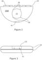
- Support 10 is further illustrated in Figures 2, 3 , 4 , 5 and 6 of the drawings.
- Support 10 has a circular shape when in an open configuration shown in Figure 1 .
- Support 10 has a diametric section hinge 19 such that support 10 is formed from two semi-circular sections which are first section 16A and a second section 16B.
- Support 10 has a clam shell-shape when in a closed configuration shown in Figure 2 .
- First and second sections 16A,16B have rounded circumferential edges 33 and tubular hinge-forming sections 20 along their straight diametric edge.
- Section hinge 19 is formed by the inter-engaging tubular sections 20 and hinge pin 21.
- the support 10 may have a different shape such as a square, rectangular or polygonal shape and section hinge 19 may be positioned so as to divide the support 10 into two sections 16A,16B having a corresponding shape.
- First section 16A has a circumferential flange 17 and second section 16B has an indented circumferential rim 18 such that when the support 10 is folded about section hinge 19 into a closed configuration, flange 17 engages rim 18 such that support 10 forms a sealed container.
- flange 17 and rim 18 may be formed from a resilient material such that the support 10 may be used on a smooth surface without sliding across when pressure is applied to it.
- First section 16A and second section 16B form a container closure 41 on their outer edge.
- Container closure 41 comprises a container closure hook 39 provided on first section 16A and a container closure clip 37 on second section 16B. In use when the support 10 is in its closed configuration, container closure hook 39 engages container closure clip 37 to secure the support 10 in its closed configuration.
- First section 16A has an upper surface which forms a container holder 12 at its centre and a lower surface having a quadrant-shaped leg 34.
- Container holder 12 has a generally circular shape with outdented corners 26 such that the container holder 12 can accommodate bottles (not shown) having a range of different sizes.
- the container holder 12 may be lined with a resilient material to support a bottle.
- the container holder 12 may have a plurality of concentric foam rings such that by selection of the appropriately sized ring, bottles of different diameters may be accommodated and supported.
- Quadrant-shaped leg 34 is attached to the lower surface of first section 16A by a two-part radial leg hinge 35 where each part of leg hinge 35 is arranged on each side of container holder 12.
- Support 10 thus has a single leg 34.
- Leg 34 has a planar shape and is formed from a plate of plastics material. Having a planar-shape, leg 34 is suitable for being held between a user's legs.
- Leg 34 is quadrant-shaped so that it can be folded into half of the semi-circular shaped first section 16A. By being formed on the lower surface of first section 16A, leg 34 is folded inside support 10 when it is in its closed configuration.
- Leg hinge 35 is substantially perpendicular to section hinge 19.
- Leg hinge 35 is arranged across the middle of section 16A such that it substantially bisects section 16A so that the support 10 is balanced when leg 34 is gripped between a user's legs.
- Leg hinge 35 is substantially perpendicular to diametric hinge 19.
- Leg 34 is shaped to fit around container holder 12 when it is folded into a stored position.
- Leg 34 has a lip 50 which is shaped to engage the lower surface of first section 16A when the leg 34 is extended by supporting the leg 34 when it is in its extended position which is a position substantially perpendicular to the lower surface of first section 16A and to prevent leg 34 from over-rotating beyond an angle of about 90° to the first section 16A.
- leg 34 may have one or more tabs at its hinge end wherein the tabs are shaped to engage the lower surface of first section 16A when the leg 34 is extended and to prevent leg 34 from over-rotating beyond an angle of about 90° to the first section 16A.
- the leg 34 may have a leg lock comprising a resilient formation at the hinge end of leg 34 which is arranged to engage with a corresponding indent on the leg hinge 35 or on the lower surface of the first section 16A such that the leg lock secures the leg 34 when it is in its extended position.
- the leg lock may comprise a resilient formation arranged on the leg hinge 35 or on the lower surface of the first section 16A and an indent may be arranged on leg 34.
- the leg 34 may be an extendable leg with a telescopic section to help stability of the support in use.
- Second section 16B has an upper surface which forms a work surface for a cosmetic treatment.
- Second section 16B has a lower surface provided with one or more clips (not shown) for storing one or more tools for use in a cosmetic treatment such as a manicure tool for example a nail file, nail clipper, pair of tweezers, cuticle cutters and/or a brush.
- a manicure tool for example a nail file, nail clipper, pair of tweezers, cuticle cutters and/or a brush.
- a person may use support 10 whilst applying a cosmetic treatment such as nail polish to their finger nails in a reclined position by using support 10 in its open configuration with its leg 34 in its extended position.
- the person can secure the first section 16A in a substantially horizontal position on their knees by gripping leg 34 between their knees.
- Section hinge 19 then allows the support 10 to fold in a manner corresponding to the angle between the person's knees and upper legs such that the second section 16B rests on the person's thighs and can be used as a convenient support for the treatment.
- a nail polish bottle can be placed in container holder 12 of the first section 16A which bottle will not spill because the first section 16A is supported in a substantially horizontal position.
- a second embodiment of a support not according to the invention is indicated generally at 110 on Figures 7 and 8 of the accompanying drawings.
- Support 110 is shown in Figures 7 and 8 with an electronic device 70 mounted on it.
- Support 110 has a generally square shape which is divided into two sections 16A,16B by section hinge 19 such that sections 16A,16B have substantially the same rectangular shape.
- First section 16A has a leg 34 on its lower side. Leg 34 is attached to the first section 16A by a leg hinge 35 which is positioned on first section 16A to be at an angle of about 90° to the section hinge 19 as for support 10.
- Leg 34 forms a finger hole 48.
- first section 16A may form a container holder (not shown) to accommodate a drinks bottle or cup.
- Support 110 has a single leg 34.
- Leg 34 has a planar shape and is formed from a plate of plastics material. Having a planar-shaped, leg 34 is easier for a user to grip between their legs.
- Leg 34 is square-shaped so that it can be folded into half of the rectangular first section 16A. By being formed on the lower surface of first section 16A, leg 34 is folded inside support 110 when it is in its closed configuration.
- Leg hinge 35 is arranged across the middle of section 16A such that it substantially bisects section 16A so that the support 10 is balanced when leg 34 is gripped between a user's legs.
- Second section 16B has a support hinge 60 on its other longitudinal edge opposing section hinge 19.
- Support hinge 60 has a magnetic fastening 65 for attachment to the electronic device 70.
- the electronic device 70 is shown on Figure 7 to have a camera 72 on its rear side and on Figure 8 to have a display screen 74 and a control button 76.
- the electronic device 70 may be a tablet computer or smart phone. In use, electronic device 70 may be folded on to the upper side of second section 16B such that its screen 74 faces a user.
- the support 110 may act as a protective container for the electronic device 70.
- a person may use support 110 whilst using the electronic device 70 in a reclined position by using support 110 in its open configuration with its leg 34 in its extended position.
- the support 110 allows a person to watch a movie or engage in a video call without having to hold the electronic device 70; in other words, the support 110 allows hands-free use of the electronic device 70.
- the person can secure the first section 16A in a substantially horizontal position on their knees by gripping leg 34 between their knees.
- Section hinge 19 then allows the support 110 to fold in a manner corresponding to the angle between the person's knees and upper legs such that the second section 16B rests on the person's thighs and can be used as a convenient support for the electronic device 70.
Landscapes
- Supports Or Holders For Household Use (AREA)
Claims (13)
- Stütze (10) zur Verwendung bei einer Freizeitaktivität oder kosmetischen Behandlungen, wobei die Stütze zwei Abschnitte (16A,16B) umfasst, die durch ein Abschnittsscharnier (19) verbunden sind, wobei ein erster Abschnitt (16A) ein einzelnes Bein (34) aufweist, das dazu geeignet ist, zwischen den Beinen eines Benutzers gehalten zu werden, wobei das Bein durch ein Beinscharnier (35) mit dem ersten Abschnitt verbunden ist und wobei das Beinscharnier im Wesentlichen senkrecht zu dem Abschnittsscharnier steht; wobei das Abschnittsscharnier so angeordnet ist, dass es die Stütze in zwei Abschnitte unterteilt, sodass die zwei Abschnitte im Wesentlichen entsprechende Formen aufweisen; wobei das Beinscharnier über der Mitte des ersten Abschnitts angeordnet ist, sodass die Stütze im Gleichgewicht ist, wenn ihr Bein zwischen den Beinen eines Benutzers festgehalten wird; wobei das Bein so geformt ist, dass es sich in die Hälfte des ersten Abschnitts klappt; und wobei das Bein einen oder mehrere Anschläge aufweist, um seine Überdrehung über einen Winkel von etwa 90° hinaus zu einer unteren Oberfläche des ersten Abschnitts zu verhindern.
- Stütze nach Anspruch 1, wobei der erste Abschnitt auf seiner oberen Oberfläche einen Behälterhalter (12) zum Aufnehmen eines Behälters zur Verwendung bei einer kosmetischen Behandlung oder eines Behälters zur Verwendung bei einer Freizeitaktivität bilden kann; wobei vorzugsweise der Behälterhalter eine flexible Form aufweist, sodass er Behälter unterschiedlicher Größe halten kann.
- Stütze nach einem der vorhergehenden Ansprüche, wobei die Stütze eine kompakte Stütze ist.
- Stütze nach einem der vorhergehenden Ansprüche, wobei die Stütze eine kreisförmige Form aufweist und das Abschnittsscharnier diametrisch ist.
- Stütze nach einem der vorhergehenden Ansprüche, wobei die Stütze eine geradlinige Form aufweist.
- Stütze nach einem der vorhergehenden Ansprüche, wobei die zwei Abschnitte entsprechend geformte Umfangsmerkmale aufweisen, die ineinandergreifen, wenn sich die Stütze in einer geschlossenen Konfiguration befindet, um einen versiegelten Behälter zu bilden.
- Stütze nach einem der vorhergehenden Ansprüche, wobei die zwei Abschnitte ein elastisches Material umfassen, um ein Verrutschen zu verringern, wenn die Stütze auf einer glatten Oberfläche verwendet wird.
- Stütze nach einem der vorhergehenden Ansprüche, wobei die Stütze einen Behälterverschluss umfasst, um die Stütze in ihrer geschlossenen Konfiguration zu sichern.
- Stütze nach einem der vorhergehenden Ansprüche, wobei der eine oder die mehreren Anschläge eine Beinlippe (50) oder einen oder mehrere Beinlaschen umfassen.
- Stütze nach einem der vorhergehenden Ansprüche, wobei das Bein eine Beinarretierung umfasst, um das Bein in seiner ausgezogenen Position zu sichern.
- Stütze nach einem der vorhergehenden Ansprüche, wobei das Bein ein Fingerloch (48) zur leichten Handhabbarkeit beim Bewegen des Beins bildet.
- Stütze nach einem der vorhergehenden Ansprüche, wobei das Bein ein ausziehbares Bein ist; wobei vorzugsweise das Bein einen Teleskopabschnitt aufweist.
- Stütze nach einem der vorhergehenden Ansprüche, wobei das Bein eine ebene Form aufweist; wobei vorzugsweise das Bein aus einer Platte aus Kunststoffmaterial gebildet ist.
Priority Applications (1)
| Application Number | Priority Date | Filing Date | Title |
|---|---|---|---|
| EP17194247.7A EP3461365B1 (de) | 2017-09-29 | 2017-09-29 | Verbesserungen an oder im zusammenhang mit stützen |
Applications Claiming Priority (1)
| Application Number | Priority Date | Filing Date | Title |
|---|---|---|---|
| EP17194247.7A EP3461365B1 (de) | 2017-09-29 | 2017-09-29 | Verbesserungen an oder im zusammenhang mit stützen |
Publications (3)
| Publication Number | Publication Date |
|---|---|
| EP3461365A1 EP3461365A1 (de) | 2019-04-03 |
| EP3461365C0 EP3461365C0 (de) | 2023-08-16 |
| EP3461365B1 true EP3461365B1 (de) | 2023-08-16 |
Family
ID=60009490
Family Applications (1)
| Application Number | Title | Priority Date | Filing Date |
|---|---|---|---|
| EP17194247.7A Active EP3461365B1 (de) | 2017-09-29 | 2017-09-29 | Verbesserungen an oder im zusammenhang mit stützen |
Country Status (1)
| Country | Link |
|---|---|
| EP (1) | EP3461365B1 (de) |
Family Cites Families (9)
| Publication number | Priority date | Publication date | Assignee | Title |
|---|---|---|---|---|
| US1728431A (en) * | 1928-02-09 | 1929-09-17 | George G Mevi | Book support |
| US2392626A (en) * | 1944-05-12 | 1946-01-08 | Rogers G Young | Finger rest |
| US2647678A (en) * | 1950-05-05 | 1953-08-04 | Douglas J Olson | Holder for paper plates and the like |
| US3121576A (en) * | 1959-10-12 | 1964-02-18 | Nat Blank Book Co | Binder case construction convertible to easel form |
| US4679757A (en) * | 1986-05-16 | 1987-07-14 | Mussari Fred P | Adjustable bookholder |
| US5248030A (en) * | 1991-11-01 | 1993-09-28 | Binney & Smith Inc. | Folding instrument container |
| US6349729B1 (en) * | 1999-05-17 | 2002-02-26 | Pop Up Nails, Inc. | Portable nail polish table |
| US7240887B2 (en) * | 2005-01-20 | 2007-07-10 | Brian Buote | Book holder |
| US9062819B1 (en) * | 2014-12-05 | 2015-06-23 | Rong Chen | Collapsible computer laptop table |
-
2017
- 2017-09-29 EP EP17194247.7A patent/EP3461365B1/de active Active
Also Published As
| Publication number | Publication date |
|---|---|
| EP3461365C0 (de) | 2023-08-16 |
| EP3461365A1 (de) | 2019-04-03 |
Similar Documents
| Publication | Publication Date | Title |
|---|---|---|
| US8827234B2 (en) | One-handed, back-based support for a hand-held object | |
| US20130140837A1 (en) | Portable computer holder with adjustable hand grip | |
| US9249922B2 (en) | Systems and methods for device holders | |
| US6640813B2 (en) | Portable accessory bag | |
| US6349729B1 (en) | Portable nail polish table | |
| US9671057B2 (en) | Support plate | |
| US20130105662A1 (en) | Easily Attachable/Detachable, Multi-Function Support For A Tablet Personal Computer | |
| US20120312955A1 (en) | Handle for hand held device | |
| US10477936B2 (en) | Integrated, manicure-pedicure station apparatus and method | |
| WO2015102662A1 (en) | Tablet computer holder | |
| US11290142B2 (en) | Grip for a mobile communication device | |
| US20120327593A1 (en) | Tablet computer holding device | |
| US9192219B2 (en) | Wrist rest apparatus | |
| US9924794B2 (en) | Platform for electronic devices | |
| US20140014552A1 (en) | Beverage carrying device | |
| US20140191099A1 (en) | Mobile Holder | |
| US20180368538A1 (en) | Assistive Holder | |
| US11172747B2 (en) | Support for use in cosmetic or leisure activity | |
| EP3461365A1 (de) | Verbesserungen an oder im zusammenhang mit stützen | |
| US8033285B2 (en) | Grooming station | |
| GB2551447A (en) | Improvements in or relating to supports | |
| US20150237995A1 (en) | Assistive Apparatus For Hand Held Vessels or Items | |
| US20150098185A1 (en) | Foldable Structure for Portable Devices | |
| US20130025204A1 (en) | Device configured for hanging, supporting, and gripping | |
| US20090229623A1 (en) | Nail Grooming Appartus |
Legal Events
| Date | Code | Title | Description |
|---|---|---|---|
| PUAI | Public reference made under article 153(3) epc to a published international application that has entered the european phase |
Free format text: ORIGINAL CODE: 0009012 |
|
| STAA | Information on the status of an ep patent application or granted ep patent |
Free format text: STATUS: THE APPLICATION HAS BEEN PUBLISHED |
|
| AK | Designated contracting states |
Kind code of ref document: A1 Designated state(s): AL AT BE BG CH CY CZ DE DK EE ES FI FR GB GR HR HU IE IS IT LI LT LU LV MC MK MT NL NO PL PT RO RS SE SI SK SM TR |
|
| AX | Request for extension of the european patent |
Extension state: BA ME |
|
| STAA | Information on the status of an ep patent application or granted ep patent |
Free format text: STATUS: REQUEST FOR EXAMINATION WAS MADE |
|
| 17P | Request for examination filed |
Effective date: 20190927 |
|
| RBV | Designated contracting states (corrected) |
Designated state(s): AL AT BE BG CH CY CZ DE DK EE ES FI FR GB GR HR HU IE IS IT LI LT LU LV MC MK MT NL NO PL PT RO RS SE SI SK SM TR |
|
| STAA | Information on the status of an ep patent application or granted ep patent |
Free format text: STATUS: EXAMINATION IS IN PROGRESS |
|
| 17Q | First examination report despatched |
Effective date: 20200916 |
|
| GRAP | Despatch of communication of intention to grant a patent |
Free format text: ORIGINAL CODE: EPIDOSNIGR1 |
|
| STAA | Information on the status of an ep patent application or granted ep patent |
Free format text: STATUS: GRANT OF PATENT IS INTENDED |
|
| RIC1 | Information provided on ipc code assigned before grant |
Ipc: A47B 13/16 20060101ALN20230214BHEP Ipc: A47B 23/00 20060101ALI20230214BHEP Ipc: A45D 29/22 20060101ALI20230214BHEP Ipc: A45D 29/00 20060101AFI20230214BHEP |
|
| INTG | Intention to grant announced |
Effective date: 20230307 |
|
| GRAS | Grant fee paid |
Free format text: ORIGINAL CODE: EPIDOSNIGR3 |
|
| GRAA | (expected) grant |
Free format text: ORIGINAL CODE: 0009210 |
|
| STAA | Information on the status of an ep patent application or granted ep patent |
Free format text: STATUS: THE PATENT HAS BEEN GRANTED |
|
| AK | Designated contracting states |
Kind code of ref document: B1 Designated state(s): AL AT BE BG CH CY CZ DE DK EE ES FI FR GR HR HU IE IS IT LI LT LU LV MC MK MT NL NO PL PT RO RS SE SI SK SM TR |
|
| RBV | Designated contracting states (corrected) |
Designated state(s): AL AT BE BG CH CY CZ DE DK EE ES FI FR GR HR HU IE IS IT LI LT LU LV MC MK MT NL NO PL PT RO RS SE SI SK SM TR |
|
| RIN1 | Information on inventor provided before grant (corrected) |
Inventor name: SALMON, CAROLINE EMMA Inventor name: SALMON, JAMES ROBERT Inventor name: DEELY, VICTORIA JANE Inventor name: DEELY, JOSEPH DANIEL |
|
| REG | Reference to a national code |
Ref country code: CH Ref legal event code: EP |
|
| REG | Reference to a national code |
Ref country code: DE Ref legal event code: R096 Ref document number: 602017072723 Country of ref document: DE |
|
| REG | Reference to a national code |
Ref country code: IE Ref legal event code: FG4D |
|
| U01 | Request for unitary effect filed |
Effective date: 20230905 |
|
| U07 | Unitary effect registered |
Designated state(s): AT BE BG DE DK EE FI FR IT LT LU LV MT NL PT SE SI Effective date: 20230912 |
|
| U20 | Renewal fee for the european patent with unitary effect paid |
Year of fee payment: 7 Effective date: 20230915 |
|
| PG25 | Lapsed in a contracting state [announced via postgrant information from national office to epo] |
Ref country code: GR Free format text: LAPSE BECAUSE OF FAILURE TO SUBMIT A TRANSLATION OF THE DESCRIPTION OR TO PAY THE FEE WITHIN THE PRESCRIBED TIME-LIMIT Effective date: 20231117 |
|
| PG25 | Lapsed in a contracting state [announced via postgrant information from national office to epo] |
Ref country code: IS Free format text: LAPSE BECAUSE OF FAILURE TO SUBMIT A TRANSLATION OF THE DESCRIPTION OR TO PAY THE FEE WITHIN THE PRESCRIBED TIME-LIMIT Effective date: 20231216 |
|
| PG25 | Lapsed in a contracting state [announced via postgrant information from national office to epo] |
Ref country code: RS Free format text: LAPSE BECAUSE OF FAILURE TO SUBMIT A TRANSLATION OF THE DESCRIPTION OR TO PAY THE FEE WITHIN THE PRESCRIBED TIME-LIMIT Effective date: 20230816 Ref country code: NO Free format text: LAPSE BECAUSE OF FAILURE TO SUBMIT A TRANSLATION OF THE DESCRIPTION OR TO PAY THE FEE WITHIN THE PRESCRIBED TIME-LIMIT Effective date: 20231116 Ref country code: IS Free format text: LAPSE BECAUSE OF FAILURE TO SUBMIT A TRANSLATION OF THE DESCRIPTION OR TO PAY THE FEE WITHIN THE PRESCRIBED TIME-LIMIT Effective date: 20231216 Ref country code: HR Free format text: LAPSE BECAUSE OF FAILURE TO SUBMIT A TRANSLATION OF THE DESCRIPTION OR TO PAY THE FEE WITHIN THE PRESCRIBED TIME-LIMIT Effective date: 20230816 Ref country code: GR Free format text: LAPSE BECAUSE OF FAILURE TO SUBMIT A TRANSLATION OF THE DESCRIPTION OR TO PAY THE FEE WITHIN THE PRESCRIBED TIME-LIMIT Effective date: 20231117 |
|
| PG25 | Lapsed in a contracting state [announced via postgrant information from national office to epo] |
Ref country code: PL Free format text: LAPSE BECAUSE OF FAILURE TO SUBMIT A TRANSLATION OF THE DESCRIPTION OR TO PAY THE FEE WITHIN THE PRESCRIBED TIME-LIMIT Effective date: 20230816 |
|
| PG25 | Lapsed in a contracting state [announced via postgrant information from national office to epo] |
Ref country code: ES Free format text: LAPSE BECAUSE OF FAILURE TO SUBMIT A TRANSLATION OF THE DESCRIPTION OR TO PAY THE FEE WITHIN THE PRESCRIBED TIME-LIMIT Effective date: 20230816 |
|
| PG25 | Lapsed in a contracting state [announced via postgrant information from national office to epo] |
Ref country code: SM Free format text: LAPSE BECAUSE OF FAILURE TO SUBMIT A TRANSLATION OF THE DESCRIPTION OR TO PAY THE FEE WITHIN THE PRESCRIBED TIME-LIMIT Effective date: 20230816 Ref country code: RO Free format text: LAPSE BECAUSE OF FAILURE TO SUBMIT A TRANSLATION OF THE DESCRIPTION OR TO PAY THE FEE WITHIN THE PRESCRIBED TIME-LIMIT Effective date: 20230816 Ref country code: ES Free format text: LAPSE BECAUSE OF FAILURE TO SUBMIT A TRANSLATION OF THE DESCRIPTION OR TO PAY THE FEE WITHIN THE PRESCRIBED TIME-LIMIT Effective date: 20230816 Ref country code: CZ Free format text: LAPSE BECAUSE OF FAILURE TO SUBMIT A TRANSLATION OF THE DESCRIPTION OR TO PAY THE FEE WITHIN THE PRESCRIBED TIME-LIMIT Effective date: 20230816 Ref country code: SK Free format text: LAPSE BECAUSE OF FAILURE TO SUBMIT A TRANSLATION OF THE DESCRIPTION OR TO PAY THE FEE WITHIN THE PRESCRIBED TIME-LIMIT Effective date: 20230816 |
|
| REG | Reference to a national code |
Ref country code: CH Ref legal event code: PL |
|
| REG | Reference to a national code |
Ref country code: DE Ref legal event code: R097 Ref document number: 602017072723 Country of ref document: DE |
|
| PG25 | Lapsed in a contracting state [announced via postgrant information from national office to epo] |
Ref country code: MC Free format text: LAPSE BECAUSE OF FAILURE TO SUBMIT A TRANSLATION OF THE DESCRIPTION OR TO PAY THE FEE WITHIN THE PRESCRIBED TIME-LIMIT Effective date: 20230816 |
|
| PLBE | No opposition filed within time limit |
Free format text: ORIGINAL CODE: 0009261 |
|
| STAA | Information on the status of an ep patent application or granted ep patent |
Free format text: STATUS: NO OPPOSITION FILED WITHIN TIME LIMIT |
|
| REG | Reference to a national code |
Ref country code: IE Ref legal event code: MM4A |
|
| PG25 | Lapsed in a contracting state [announced via postgrant information from national office to epo] |
Ref country code: IE Free format text: LAPSE BECAUSE OF NON-PAYMENT OF DUE FEES Effective date: 20230929 |
|
| PG25 | Lapsed in a contracting state [announced via postgrant information from national office to epo] |
Ref country code: CH Free format text: LAPSE BECAUSE OF NON-PAYMENT OF DUE FEES Effective date: 20230930 |
|
| 26N | No opposition filed |
Effective date: 20240517 |
|
| PG25 | Lapsed in a contracting state [announced via postgrant information from national office to epo] |
Ref country code: IE Free format text: LAPSE BECAUSE OF NON-PAYMENT OF DUE FEES Effective date: 20230929 Ref country code: CH Free format text: LAPSE BECAUSE OF NON-PAYMENT OF DUE FEES Effective date: 20230930 |
|
| U20 | Renewal fee for the european patent with unitary effect paid |
Year of fee payment: 8 Effective date: 20240923 |
|
| PG25 | Lapsed in a contracting state [announced via postgrant information from national office to epo] |
Ref country code: CY Free format text: LAPSE BECAUSE OF FAILURE TO SUBMIT A TRANSLATION OF THE DESCRIPTION OR TO PAY THE FEE WITHIN THE PRESCRIBED TIME-LIMIT; INVALID AB INITIO Effective date: 20170929 |
|
| PG25 | Lapsed in a contracting state [announced via postgrant information from national office to epo] |
Ref country code: HU Free format text: LAPSE BECAUSE OF FAILURE TO SUBMIT A TRANSLATION OF THE DESCRIPTION OR TO PAY THE FEE WITHIN THE PRESCRIBED TIME-LIMIT; INVALID AB INITIO Effective date: 20170929 |
|
| PG25 | Lapsed in a contracting state [announced via postgrant information from national office to epo] |
Ref country code: TR Free format text: LAPSE BECAUSE OF FAILURE TO SUBMIT A TRANSLATION OF THE DESCRIPTION OR TO PAY THE FEE WITHIN THE PRESCRIBED TIME-LIMIT Effective date: 20230816 |
|
| U1N | Appointed representative for the unitary patent procedure changed after the registration of the unitary effect |
Representative=s name: SCHLICH; GB |
|
| U90 | Renewal fees not paid: noting of loss of rights |
Free format text: RENEWAL FEE NOT PAID FOR YEAR 09 Effective date: 20260416 |