EP3461010B1 - Radiosystem mit einer schiebehalterung für ein tragbares radio und zugehörige verfahren - Google Patents
Radiosystem mit einer schiebehalterung für ein tragbares radio und zugehörige verfahren Download PDFInfo
- Publication number
- EP3461010B1 EP3461010B1 EP18195929.7A EP18195929A EP3461010B1 EP 3461010 B1 EP3461010 B1 EP 3461010B1 EP 18195929 A EP18195929 A EP 18195929A EP 3461010 B1 EP3461010 B1 EP 3461010B1
- Authority
- EP
- European Patent Office
- Prior art keywords
- mount
- mounting rail
- housing
- elongate mounting
- carried
- Prior art date
- Legal status (The legal status is an assumption and is not a legal conclusion. Google has not performed a legal analysis and makes no representation as to the accuracy of the status listed.)
- Active
Links
Images

Classifications
-
- F—MECHANICAL ENGINEERING; LIGHTING; HEATING; WEAPONS; BLASTING
- F41—WEAPONS
- F41G—WEAPON SIGHTS; AIMING
- F41G1/00—Sighting devices
- F41G1/38—Telescopic sights specially adapted for smallarms or ordnance; Supports or mountings therefor
- F41G1/387—Mounting telescopic sights on smallarms
-
- B—PERFORMING OPERATIONS; TRANSPORTING
- B60—VEHICLES IN GENERAL
- B60R—VEHICLES, VEHICLE FITTINGS, OR VEHICLE PARTS, NOT OTHERWISE PROVIDED FOR
- B60R11/00—Arrangements for holding or mounting articles, not otherwise provided for
- B60R11/02—Arrangements for holding or mounting articles, not otherwise provided for for radio sets, television sets, telephones, or the like; Arrangement of controls thereof
- B60R11/0205—Arrangements for holding or mounting articles, not otherwise provided for for radio sets, television sets, telephones, or the like; Arrangement of controls thereof for radio sets
-
- F—MECHANICAL ENGINEERING; LIGHTING; HEATING; WEAPONS; BLASTING
- F41—WEAPONS
- F41A—FUNCTIONAL FEATURES OR DETAILS COMMON TO BOTH SMALLARMS AND ORDNANCE, e.g. CANNONS; MOUNTINGS FOR SMALLARMS OR ORDNANCE
- F41A23/00—Gun mountings, e.g. on vehicles; Disposition of guns on vehicles
- F41A23/02—Mountings without wheels
- F41A23/08—Bipods
-
- F—MECHANICAL ENGINEERING; LIGHTING; HEATING; WEAPONS; BLASTING
- F41—WEAPONS
- F41C—SMALLARMS, e.g. PISTOLS, RIFLES; ACCESSORIES THEREFOR
- F41C23/00—Butts; Butt plates; Stocks
- F41C23/16—Forestocks; Handgrips; Hand guards
-
- F—MECHANICAL ENGINEERING; LIGHTING; HEATING; WEAPONS; BLASTING
- F41—WEAPONS
- F41C—SMALLARMS, e.g. PISTOLS, RIFLES; ACCESSORIES THEREFOR
- F41C27/00—Accessories; Details or attachments not otherwise provided for
-
- F—MECHANICAL ENGINEERING; LIGHTING; HEATING; WEAPONS; BLASTING
- F41—WEAPONS
- F41G—WEAPON SIGHTS; AIMING
- F41G11/00—Details of sighting or aiming apparatus; Accessories
- F41G11/001—Means for mounting tubular or beam shaped sighting or aiming devices on firearms
- F41G11/003—Mountings with a dove tail element, e.g. "Picatinny rail systems"
-
- H—ELECTRICITY
- H04—ELECTRIC COMMUNICATION TECHNIQUE
- H04B—TRANSMISSION
- H04B1/00—Details of transmission systems, not covered by a single one of groups H04B3/00 - H04B13/00; Details of transmission systems not characterised by the medium used for transmission
- H04B1/38—Transceivers, i.e. devices in which transmitter and receiver form a structural unit and in which at least one part is used for functions of transmitting and receiving
- H04B1/3827—Portable transceivers
- H04B1/3877—Arrangements for enabling portable transceivers to be used in a fixed position, e.g. cradles or boosters
Definitions
- the radio system may further comprise a locking device carried by the mount body.
- the locking device may comprise a lock body coupled to the mount body at an end thereof, a manual actuating member carried by the lock body, and a locking pin carried by the lock body and moveable between locked and unlocked positions responsive to the manual actuating member.
- the locking device may further comprise a worm gear arrangement coupling the manual actuating member and the locking pin.
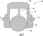
- the at least one spring plunger may comprise a housing having an end opening and an interior cavity coupled thereto, a ball moveable within the cavity, and a spring biasing the ball to an extended position exposed at the end opening of the housing.
- the at least one spring plunger may comprise three spring plungers arranged in spaced relation.
- a vehicle mount may carry the at least one elongate mounting rail.
- the portable radio may comprise a manpack portable radio or a handheld portable radio.
- a method of mounting a portable radio to at least one elongate mounting rail having a plurality of spaced apart indentations therein comprises slidably positioning at least one sliding mount along the at least one elongate mounting rail.
- the at least one sliding mount comprises a mount body having a passageway therethrough slidably receiving the corresponding elongate mounting rail, and coupled to the portable radio, and at least one spring plunger carried by the mount body and configured to engage at least one adjacent indentation in the elongate mounting rail.
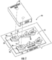
- FIG. 1 there is illustrated the radio system indicated generally at 10 that includes a portable radio 12, which in this example is a manpack portable radio.
- a portable radio 12 which in this example is a manpack portable radio.
- Two elongate mounting rails 14 are supported via shock absorbers 16 on a vehicle mount 18, which in turn, is mounted on a vehicle surface 20.
- Each elongate mounting rail 14 includes a plurality of linearly aligned, spaced apart indentations 20, also shown in FIGS. 2 and 3 , and in this example are formed as through holes, but could be formed as small recesses and not extend through the elongate mounting rail 14.
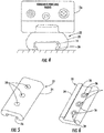
- the portable radio 12 is coupled to a sliding mount indicated generally at 22 and includes a mount body 24 having a passageway 26 therethrough as best shown in FIGS. 5 and 6 .
- the passageway 26 receives the corresponding elongate mounting rail 14 so that each mount body 24 is slidable on the corresponding elongate mounting rail.
- a handheld portable radio 12a in this example is coupled to only one mount body 24 that receives in its passageway 26 an elongate mounting rail 14.
- Each sliding mount 22 includes at least one spring plunger 28 carried by the mount body 24 and configured to engage at least one adjacent indentation 20 in the elongate mounting rail 14.
- each mount body 24 includes three linearly spaced spring plungers 28, which are received in orifices formed in the respective mount body.
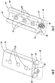
- the worm gear arrangement 48' is rotated slightly to move the locking pin 46' into a locked or unlocked position where the locking pin engages an indentation 20' in the mounting rail 14'.
- Other locking device designs may be used, including quick release pins that engage an indentation 20' or a cam driven mechanism.
- the corresponding elongate mounting rail 14 may be shortened to a few inches and include a pivotally mounted attachment leg (not shown) that may be spring biased to permit the shortened elongate mounting rail 14 to be attached to a vest for temporary securement.
- a handheld portable radio may be mounted onto the sliding mount 22 that receives the shortened elongate mounting rail 14 having about the same length as the sliding mount 22.
- the mounting rail 14 may be inserted within a vest pocket and held therein by the pivotally mounted attachment leg to hold the radio in a temporary position so that it may be quickly grasped.
- a method of mounting the portable radio 12 to at least one elongate mounting rail 14 having a plurality of spaced apart indentations 20 therein is provided by slidably positioning at least one sliding mount 22 along the at least one elongate mounting rail.
- the at least one sliding mount 22 includes a mount body 24 having a passageway 26 therethrough slidably receiving the corresponding elongate mounting rail 26 and coupled to the portable radio 12.
- At least one spring plunger is carried by the mount body 24 and configured to engage at least one adjacent indentation 20 in the corresponding elongate mounting rail 14.
Landscapes
- Engineering & Computer Science (AREA)
- General Engineering & Computer Science (AREA)
- Physics & Mathematics (AREA)
- Optics & Photonics (AREA)
- Mechanical Engineering (AREA)
- Computer Networks & Wireless Communication (AREA)
- Signal Processing (AREA)
- Casings For Electric Apparatus (AREA)
Claims (9)
- Funksystem (10), aufweisend:ein mobiles Funkgerät (12);mindestens eine langgestreckte Einbauschiene (14) mit einer Mehrzahl beabstandeter Vertiefungen darin; undmindestens eine Schiebehalterung (22), die einen Halterungskörper (24) mit einem Durchgang (26) aufweist, in dem die langgestreckte Einbauschiene (14) verschieblich aufgenommen ist, und die mit dem mobilen Funkgerät (12) gekoppelt ist, wobei jede Schiebehalterung (22) mindestens eine sich in den Durchgang (26) erstreckende Öffnung aufweist, undmindestens einen auf dem Halterungskörper (24) angeordneten Federstößel (28), der zum Eingriff in mindestens eine benachbarte Vertiefung in der entsprechenden langgestreckten Einbauschiene (14) konfiguriert ist;dadurch gekennzeichnet, dass der mindestens eine Federstößel (28) aufweist:
ein Gehäuse (30) mit einer Öffnung (32) und einem damit gekoppeltem inneren Hohlraum (34) sowie einem O-Ring (31) am Gehäuse zur besseren Sicherung des Gehäuses in der Öffnung,wobei das Gehäuse (30) in seiner Außenabmessung für den O-Ring (31) dimensioniert ist,eine Kugel (36), die innerhalb des Hohlraums (34) beweglich ist, undeine Feder (38), die die Kugel in eine hervorstehende Position am Ende der Öffnung des Gehäuses vorspannt. - Funksystem (10) nach Anspruch 1, das ferner eine auf dem Halterungskörper (24) angeordnete Arretiereinrichtung (40') aufweist, um den Halterungskörper (24) auf der entsprechenden langgestreckten Einbauschiene (14) zu arretieren.
- Funksystem (10) nach Anspruch 2, wobei die Arretiereinrichtung (40') aufweist:einen Arretierkörper (42'), der mit dem Halterungskörper (24) an einem Ende desselben gekoppelt ist;ein manuelles Betätigungselement (44'), das im Arretierkörper (42') angebracht ist; undeinen Arretierzapfen (46), der am Arrerierkörper (42') angebracht und als Reaktion auf das manuelle Betätigungselement (44') zwischen der arretierten und der nicht arretierten Position beweglich ist.
- Funksystem (10) nach Anspruch 3, wobei die Arretiereinrichtung (40') ferner eine Schneckenradanordnung (48') aufweist, die das manuelle Betätigungselement (44') mit dem Arretierzapfen (46) koppelt.
- Schiebehalterung (22) für eine langgestreckte Einbauschiene (14) mit einer Mehrzahl beabstandeter Vertiefungen darin und aufweisend:
einen Halterungskörper (24) mit einem Durchgang (26), in dem die langgestreckte Einbauschiene (14) verschieblich aufgenommen ist, und der mit dem mobilen Funkgerät (12) gekoppelt ist;
mindestens eine sich in den Durchgang (26) erstreckende Öffnung; und
mindestens einen auf dem Halterungskörper (24) angeordneten Federstößel (28), der zum Eingriff in mindestens eine benachbarte Vertiefung in der langgestreckten Einbauschiene (14) konfiguriert ist;
wobei der Federstößel (28) aufweist:
ein Gehäuse (30) mit einer Öffnung (32) und einem damit gekoppeltem inneren Hohlraum (34) sowie einem O-Ring am Gehäuse zur besseren Sicherung des Gehäuses in der Öffnung,
wobei das Gehäuse (30) in seiner Außenabmessung für den O-Ring (31) dimensioniert ist,
eine Kugel (36), die innerhalb des Hohlraums (34) beweglich ist, und
eine Feder (38), die die Kugel in eine hervorstehende Position am Ende der Öffnung des Gehäuses vorspannt. - Schiebehalterung (22) nach Anspruch 5, die ferner eine auf dem Halterungskörper (24) angeordnete Arretiereinrichtung (40') aufweist, um den Halterungskörper (24) auf der entsprechenden langgestreckten Einbauschiene (14) zu arretieren.
- Schiebehalterung (22) nach Anspruch 6, wobei die Arretiereinrichtung (40') aufweist:einen Arretierkörper (42'), der mit dem Halterungskörper (24) an einem Ende desselben gekoppelt ist;ein manuelles Betätigungselement (44'), das am Arretierkörper (42') angebracht ist; undeinen Arretierzapfen (46), der am Arretierkörper (42') angebracht und als Reaktion auf das manuelle Betätigungselement (44') zwischen der arretierten und der nicht arretierten Position beweglich ist.
- Schiebehalterung (22) nach Anspruch 7, wobei die Arretiereinrichtung (40') ferner eine Schneckenradanordnung (48') aufweist, die das manuelle Betätigungselement (44') mit dem Arretierzapfen (46) koppelt
- Schiebehalterung (22) nach Anspruch 5, wobei der mindestens eine Federstößel (28) drei Federstößel (28) aufweist, die in einer beabstandeten Beziehung angeordnet sind.
Applications Claiming Priority (1)
| Application Number | Priority Date | Filing Date | Title |
|---|---|---|---|
| US15/715,213 US10119786B1 (en) | 2017-09-26 | 2017-09-26 | Radio system having a sliding mount for a portable radio and related methods |
Publications (2)
| Publication Number | Publication Date |
|---|---|
| EP3461010A1 EP3461010A1 (de) | 2019-03-27 |
| EP3461010B1 true EP3461010B1 (de) | 2020-04-01 |
Family
ID=63678476
Family Applications (1)
| Application Number | Title | Priority Date | Filing Date |
|---|---|---|---|
| EP18195929.7A Active EP3461010B1 (de) | 2017-09-26 | 2018-09-21 | Radiosystem mit einer schiebehalterung für ein tragbares radio und zugehörige verfahren |
Country Status (3)
| Country | Link |
|---|---|
| US (1) | US10119786B1 (de) |
| EP (1) | EP3461010B1 (de) |
| IL (1) | IL260467B (de) |
Families Citing this family (1)
| Publication number | Priority date | Publication date | Assignee | Title |
|---|---|---|---|---|
| US10921096B2 (en) * | 2017-09-30 | 2021-02-16 | Robert E. Stewart | Mounting and fastening system and mounting adapter |
Family Cites Families (12)
| Publication number | Priority date | Publication date | Assignee | Title |
|---|---|---|---|---|
| US5174223A (en) * | 1989-09-20 | 1992-12-29 | Nagy Marta K | Ergonomically designed computer workstation adjustable to various sitting and standing positions |
| US20040000083A1 (en) | 2002-07-01 | 2004-01-01 | Grant James Emmett | Multiple rail adapter |
| US7222451B2 (en) | 2004-02-12 | 2007-05-29 | Da Keng | Quick disconnect bipod mount and clamp assembly |
| KR100816505B1 (ko) * | 2005-09-09 | 2008-03-24 | 배석희 | 랩탑테이블 |
| US20090167634A1 (en) * | 2007-12-28 | 2009-07-02 | Evga Corporation | Systems having detachable twin display monitors |
| US8499484B2 (en) | 2011-02-17 | 2013-08-06 | LW Schneider Incorporated | Assembly for mounting on a picatinny-type rail |
| CA2781357A1 (en) | 2012-06-28 | 2013-12-28 | Lorenzo Zappia | Hawk for retaining tools |
| US9622529B2 (en) | 2012-07-18 | 2017-04-18 | Wilcox Industries Corp. | Helmet edge trim wiring harness |
| US20140252187A1 (en) | 2013-02-05 | 2014-09-11 | Cody Petrovic | Modular mounting system using picatinny-type rail |
| US9632187B2 (en) | 2013-06-12 | 2017-04-25 | The Regents Of The University Of California | Modular positron emission tomography kit |
| US9591255B2 (en) | 2014-07-18 | 2017-03-07 | Solid Proof Technologies LLC | Emergency assistance method and device for a firearm |
| US9599430B1 (en) | 2015-08-25 | 2017-03-21 | WHG Properties, LLC | Firearm handguard |
-
2017
- 2017-09-26 US US15/715,213 patent/US10119786B1/en active Active
-
2018
- 2018-07-08 IL IL260467A patent/IL260467B/en active IP Right Grant
- 2018-09-21 EP EP18195929.7A patent/EP3461010B1/de active Active
Non-Patent Citations (1)
| Title |
|---|
| None * |
Also Published As
| Publication number | Publication date |
|---|---|
| IL260467B (en) | 2019-03-31 |
| EP3461010A1 (de) | 2019-03-27 |
| US10119786B1 (en) | 2018-11-06 |
Similar Documents
| Publication | Publication Date | Title |
|---|---|---|
| US8499485B2 (en) | Sliding mount adapter device | |
| US8327574B2 (en) | System for mounting an accessory to a firearm | |
| US8276307B2 (en) | Mount adapter device utilizing a push system | |
| US9664479B1 (en) | Adjustable firearm stock | |
| US9664476B1 (en) | Adjustable firearm stock | |
| EP3081840B1 (de) | Verriegelungsanordnung | |
| EP3407006B1 (de) | Kinematische schienenhalterung zur montage einer vorrichtung an einer schusswaffenschiene | |
| US9453707B2 (en) | Systems and methods for a scope mount assembly | |
| US6517133B2 (en) | Sighting mount device | |
| US20190056195A1 (en) | Equipment retention system | |
| US7703231B2 (en) | Gun attachment holder | |
| US8793921B1 (en) | Tangent integrated tilt sight | |
| EP4166896A1 (de) | Modulare hybride schwalbenschwanzschienenklemmanordnung | |
| US20040244259A1 (en) | Mounting assembly for a weapon accessory | |
| US9573268B2 (en) | Swivel handle assembly | |
| US20140096429A1 (en) | System for mounting an accessory to a firearm | |
| US6385892B1 (en) | Bayonet lug clamp and mount assembly | |
| US9784527B2 (en) | Securing platform accessories | |
| US20060162227A1 (en) | Pivoting mount for a firearm accessory | |
| DK3106826T3 (en) | Adapter piece and handgun with such adapter piece | |
| US20060207156A1 (en) | Mount for firearm sighting device having throw-lever clamp and lever safety latch | |
| EP3407005B1 (de) | Kinematische schienenhalterung zur montage einer vorrichtung an einer schusswaffenschiene | |
| US10458746B2 (en) | Adjustable cheek riser | |
| WO2006069092A3 (en) | Indexed optical fiber connector | |
| US20170261288A1 (en) | Technologies for firearm accessory mounting |
Legal Events
| Date | Code | Title | Description |
|---|---|---|---|
| PUAI | Public reference made under article 153(3) epc to a published international application that has entered the european phase |
Free format text: ORIGINAL CODE: 0009012 |
|
| STAA | Information on the status of an ep patent application or granted ep patent |
Free format text: STATUS: REQUEST FOR EXAMINATION WAS MADE |
|
| 17P | Request for examination filed |
Effective date: 20180921 |
|
| AK | Designated contracting states |
Kind code of ref document: A1 Designated state(s): AL AT BE BG CH CY CZ DE DK EE ES FI FR GB GR HR HU IE IS IT LI LT LU LV MC MK MT NL NO PL PT RO RS SE SI SK SM TR |
|
| AX | Request for extension of the european patent |
Extension state: BA ME |
|
| GRAP | Despatch of communication of intention to grant a patent |
Free format text: ORIGINAL CODE: EPIDOSNIGR1 |
|
| STAA | Information on the status of an ep patent application or granted ep patent |
Free format text: STATUS: GRANT OF PATENT IS INTENDED |
|
| INTG | Intention to grant announced |
Effective date: 20191029 |
|
| GRAS | Grant fee paid |
Free format text: ORIGINAL CODE: EPIDOSNIGR3 |
|
| GRAA | (expected) grant |
Free format text: ORIGINAL CODE: 0009210 |
|
| STAA | Information on the status of an ep patent application or granted ep patent |
Free format text: STATUS: THE PATENT HAS BEEN GRANTED |
|
| AK | Designated contracting states |
Kind code of ref document: B1 Designated state(s): AL AT BE BG CH CY CZ DE DK EE ES FI FR GB GR HR HU IE IS IT LI LT LU LV MC MK MT NL NO PL PT RO RS SE SI SK SM TR |
|
| REG | Reference to a national code |
Ref country code: GB Ref legal event code: FG4D |
|
| REG | Reference to a national code |
Ref country code: CH Ref legal event code: EP Ref country code: AT Ref legal event code: REF Ref document number: 1252697 Country of ref document: AT Kind code of ref document: T Effective date: 20200415 |
|
| REG | Reference to a national code |
Ref country code: DE Ref legal event code: R096 Ref document number: 602018003428 Country of ref document: DE |
|
| REG | Reference to a national code |
Ref country code: IE Ref legal event code: FG4D |
|
| PG25 | Lapsed in a contracting state [announced via postgrant information from national office to epo] |
Ref country code: BG Free format text: LAPSE BECAUSE OF FAILURE TO SUBMIT A TRANSLATION OF THE DESCRIPTION OR TO PAY THE FEE WITHIN THE PRESCRIBED TIME-LIMIT Effective date: 20200701 |
|
| REG | Reference to a national code |
Ref country code: NL Ref legal event code: MP Effective date: 20200401 |
|
| REG | Reference to a national code |
Ref country code: DE Ref legal event code: R082 Ref document number: 602018003428 Country of ref document: DE Representative=s name: WUESTHOFF & WUESTHOFF, PATENTANWAELTE PARTG MB, DE Ref country code: DE Ref legal event code: R081 Ref document number: 602018003428 Country of ref document: DE Owner name: HARRIS GLOBAL COMMUNICATIONS, INC., ROCHESTER, US Free format text: FORMER OWNER: HARRIS SOLUTIONS NY, INC., ROCHESTER, NY, US |
|
| REG | Reference to a national code |
Ref country code: LT Ref legal event code: MG4D |
|
| PG25 | Lapsed in a contracting state [announced via postgrant information from national office to epo] |
Ref country code: NO Free format text: LAPSE BECAUSE OF FAILURE TO SUBMIT A TRANSLATION OF THE DESCRIPTION OR TO PAY THE FEE WITHIN THE PRESCRIBED TIME-LIMIT Effective date: 20200701 Ref country code: LT Free format text: LAPSE BECAUSE OF FAILURE TO SUBMIT A TRANSLATION OF THE DESCRIPTION OR TO PAY THE FEE WITHIN THE PRESCRIBED TIME-LIMIT Effective date: 20200401 Ref country code: PT Free format text: LAPSE BECAUSE OF FAILURE TO SUBMIT A TRANSLATION OF THE DESCRIPTION OR TO PAY THE FEE WITHIN THE PRESCRIBED TIME-LIMIT Effective date: 20200817 Ref country code: FI Free format text: LAPSE BECAUSE OF FAILURE TO SUBMIT A TRANSLATION OF THE DESCRIPTION OR TO PAY THE FEE WITHIN THE PRESCRIBED TIME-LIMIT Effective date: 20200401 Ref country code: IS Free format text: LAPSE BECAUSE OF FAILURE TO SUBMIT A TRANSLATION OF THE DESCRIPTION OR TO PAY THE FEE WITHIN THE PRESCRIBED TIME-LIMIT Effective date: 20200801 Ref country code: SE Free format text: LAPSE BECAUSE OF FAILURE TO SUBMIT A TRANSLATION OF THE DESCRIPTION OR TO PAY THE FEE WITHIN THE PRESCRIBED TIME-LIMIT Effective date: 20200401 Ref country code: GR Free format text: LAPSE BECAUSE OF FAILURE TO SUBMIT A TRANSLATION OF THE DESCRIPTION OR TO PAY THE FEE WITHIN THE PRESCRIBED TIME-LIMIT Effective date: 20200702 Ref country code: CZ Free format text: LAPSE BECAUSE OF FAILURE TO SUBMIT A TRANSLATION OF THE DESCRIPTION OR TO PAY THE FEE WITHIN THE PRESCRIBED TIME-LIMIT Effective date: 20200401 Ref country code: NL Free format text: LAPSE BECAUSE OF FAILURE TO SUBMIT A TRANSLATION OF THE DESCRIPTION OR TO PAY THE FEE WITHIN THE PRESCRIBED TIME-LIMIT Effective date: 20200401 |
|
| REG | Reference to a national code |
Ref country code: AT Ref legal event code: MK05 Ref document number: 1252697 Country of ref document: AT Kind code of ref document: T Effective date: 20200401 |
|
| PG25 | Lapsed in a contracting state [announced via postgrant information from national office to epo] |
Ref country code: RS Free format text: LAPSE BECAUSE OF FAILURE TO SUBMIT A TRANSLATION OF THE DESCRIPTION OR TO PAY THE FEE WITHIN THE PRESCRIBED TIME-LIMIT Effective date: 20200401 Ref country code: LV Free format text: LAPSE BECAUSE OF FAILURE TO SUBMIT A TRANSLATION OF THE DESCRIPTION OR TO PAY THE FEE WITHIN THE PRESCRIBED TIME-LIMIT Effective date: 20200401 Ref country code: HR Free format text: LAPSE BECAUSE OF FAILURE TO SUBMIT A TRANSLATION OF THE DESCRIPTION OR TO PAY THE FEE WITHIN THE PRESCRIBED TIME-LIMIT Effective date: 20200401 |
|
| PG25 | Lapsed in a contracting state [announced via postgrant information from national office to epo] |
Ref country code: AL Free format text: LAPSE BECAUSE OF FAILURE TO SUBMIT A TRANSLATION OF THE DESCRIPTION OR TO PAY THE FEE WITHIN THE PRESCRIBED TIME-LIMIT Effective date: 20200401 |
|
| REG | Reference to a national code |
Ref country code: DE Ref legal event code: R097 Ref document number: 602018003428 Country of ref document: DE |
|
| PG25 | Lapsed in a contracting state [announced via postgrant information from national office to epo] |
Ref country code: ES Free format text: LAPSE BECAUSE OF FAILURE TO SUBMIT A TRANSLATION OF THE DESCRIPTION OR TO PAY THE FEE WITHIN THE PRESCRIBED TIME-LIMIT Effective date: 20200401 Ref country code: SM Free format text: LAPSE BECAUSE OF FAILURE TO SUBMIT A TRANSLATION OF THE DESCRIPTION OR TO PAY THE FEE WITHIN THE PRESCRIBED TIME-LIMIT Effective date: 20200401 Ref country code: DK Free format text: LAPSE BECAUSE OF FAILURE TO SUBMIT A TRANSLATION OF THE DESCRIPTION OR TO PAY THE FEE WITHIN THE PRESCRIBED TIME-LIMIT Effective date: 20200401 Ref country code: AT Free format text: LAPSE BECAUSE OF FAILURE TO SUBMIT A TRANSLATION OF THE DESCRIPTION OR TO PAY THE FEE WITHIN THE PRESCRIBED TIME-LIMIT Effective date: 20200401 Ref country code: RO Free format text: LAPSE BECAUSE OF FAILURE TO SUBMIT A TRANSLATION OF THE DESCRIPTION OR TO PAY THE FEE WITHIN THE PRESCRIBED TIME-LIMIT Effective date: 20200401 Ref country code: EE Free format text: LAPSE BECAUSE OF FAILURE TO SUBMIT A TRANSLATION OF THE DESCRIPTION OR TO PAY THE FEE WITHIN THE PRESCRIBED TIME-LIMIT Effective date: 20200401 |
|
| PLBE | No opposition filed within time limit |
Free format text: ORIGINAL CODE: 0009261 |
|
| STAA | Information on the status of an ep patent application or granted ep patent |
Free format text: STATUS: NO OPPOSITION FILED WITHIN TIME LIMIT |
|
| PG25 | Lapsed in a contracting state [announced via postgrant information from national office to epo] |
Ref country code: PL Free format text: LAPSE BECAUSE OF FAILURE TO SUBMIT A TRANSLATION OF THE DESCRIPTION OR TO PAY THE FEE WITHIN THE PRESCRIBED TIME-LIMIT Effective date: 20200401 Ref country code: SK Free format text: LAPSE BECAUSE OF FAILURE TO SUBMIT A TRANSLATION OF THE DESCRIPTION OR TO PAY THE FEE WITHIN THE PRESCRIBED TIME-LIMIT Effective date: 20200401 |
|
| 26N | No opposition filed |
Effective date: 20210112 |
|
| PG25 | Lapsed in a contracting state [announced via postgrant information from national office to epo] |
Ref country code: SI Free format text: LAPSE BECAUSE OF FAILURE TO SUBMIT A TRANSLATION OF THE DESCRIPTION OR TO PAY THE FEE WITHIN THE PRESCRIBED TIME-LIMIT Effective date: 20200401 |
|
| REG | Reference to a national code |
Ref country code: BE Ref legal event code: MM Effective date: 20200930 |
|
| PG25 | Lapsed in a contracting state [announced via postgrant information from national office to epo] |
Ref country code: LU Free format text: LAPSE BECAUSE OF NON-PAYMENT OF DUE FEES Effective date: 20200921 |
|
| PG25 | Lapsed in a contracting state [announced via postgrant information from national office to epo] |
Ref country code: BE Free format text: LAPSE BECAUSE OF NON-PAYMENT OF DUE FEES Effective date: 20200930 Ref country code: IE Free format text: LAPSE BECAUSE OF NON-PAYMENT OF DUE FEES Effective date: 20200921 |
|
| REG | Reference to a national code |
Ref country code: CH Ref legal event code: PL |
|
| PG25 | Lapsed in a contracting state [announced via postgrant information from national office to epo] |
Ref country code: TR Free format text: LAPSE BECAUSE OF FAILURE TO SUBMIT A TRANSLATION OF THE DESCRIPTION OR TO PAY THE FEE WITHIN THE PRESCRIBED TIME-LIMIT Effective date: 20200401 Ref country code: MT Free format text: LAPSE BECAUSE OF FAILURE TO SUBMIT A TRANSLATION OF THE DESCRIPTION OR TO PAY THE FEE WITHIN THE PRESCRIBED TIME-LIMIT Effective date: 20200401 Ref country code: CY Free format text: LAPSE BECAUSE OF FAILURE TO SUBMIT A TRANSLATION OF THE DESCRIPTION OR TO PAY THE FEE WITHIN THE PRESCRIBED TIME-LIMIT Effective date: 20200401 |
|
| PG25 | Lapsed in a contracting state [announced via postgrant information from national office to epo] |
Ref country code: MK Free format text: LAPSE BECAUSE OF FAILURE TO SUBMIT A TRANSLATION OF THE DESCRIPTION OR TO PAY THE FEE WITHIN THE PRESCRIBED TIME-LIMIT Effective date: 20200401 Ref country code: MC Free format text: LAPSE BECAUSE OF FAILURE TO SUBMIT A TRANSLATION OF THE DESCRIPTION OR TO PAY THE FEE WITHIN THE PRESCRIBED TIME-LIMIT Effective date: 20200401 |
|
| PG25 | Lapsed in a contracting state [announced via postgrant information from national office to epo] |
Ref country code: LI Free format text: LAPSE BECAUSE OF NON-PAYMENT OF DUE FEES Effective date: 20210930 Ref country code: CH Free format text: LAPSE BECAUSE OF NON-PAYMENT OF DUE FEES Effective date: 20210930 |
|
| P01 | Opt-out of the competence of the unified patent court (upc) registered |
Effective date: 20230530 |
|
| PGFP | Annual fee paid to national office [announced via postgrant information from national office to epo] |
Ref country code: DE Payment date: 20250929 Year of fee payment: 8 |
|
| PGFP | Annual fee paid to national office [announced via postgrant information from national office to epo] |
Ref country code: IT Payment date: 20250919 Year of fee payment: 8 |
|
| PGFP | Annual fee paid to national office [announced via postgrant information from national office to epo] |
Ref country code: GB Payment date: 20250929 Year of fee payment: 8 |
|
| PGFP | Annual fee paid to national office [announced via postgrant information from national office to epo] |
Ref country code: FR Payment date: 20250925 Year of fee payment: 8 |