EP3407005B1 - Kinematische schienenhalterung zur montage einer vorrichtung an einer schusswaffenschiene - Google Patents
Kinematische schienenhalterung zur montage einer vorrichtung an einer schusswaffenschiene Download PDFInfo
- Publication number
- EP3407005B1 EP3407005B1 EP18173573.9A EP18173573A EP3407005B1 EP 3407005 B1 EP3407005 B1 EP 3407005B1 EP 18173573 A EP18173573 A EP 18173573A EP 3407005 B1 EP3407005 B1 EP 3407005B1
- Authority
- EP
- European Patent Office
- Prior art keywords
- rail
- frame
- mount
- kinematic
- raised pad
- Prior art date
- Legal status (The legal status is an assumption and is not a legal conclusion. Google has not performed a legal analysis and makes no representation as to the accuracy of the status listed.)
- Active
Links
- 230000000284 resting effect Effects 0.000 description 4
- 230000000452 restraining effect Effects 0.000 description 4
- 238000000034 method Methods 0.000 description 2
- 238000013459 approach Methods 0.000 description 1
- 238000004519 manufacturing process Methods 0.000 description 1
Images





Classifications
-
- F—MECHANICAL ENGINEERING; LIGHTING; HEATING; WEAPONS; BLASTING
- F41—WEAPONS
- F41G—WEAPON SIGHTS; AIMING
- F41G11/00—Details of sighting or aiming apparatus; Accessories
- F41G11/001—Means for mounting tubular or beam shaped sighting or aiming devices on firearms
- F41G11/003—Mountings with a dove tail element, e.g. "Picatinny rail systems"
Definitions
- the present disclosure relates to a mount for mounting a device on a firearm rail.
- Firearms have been around a long time, and their designs have evolved greatly and continue to evolve.
- One aspect of this evolution is that modern firearms have become more modular.
- many modern firearms include an accessory rail on which various devices, such as a telescopic sight, a holographic sight, a laser sight, a flashlight, etc., may be mounted.
- various devices such as a telescopic sight, a holographic sight, a laser sight, a flashlight, etc.
- these existing mounts generally suffer from drawbacks outlined below.
- the point of aim of the sight would need to be adjusted to match the point of impact of the firearm. This process is generally known as "zeroing" the sight, which can be an arduous task for most shooters.
- zeroing the sight
- a shooter may want to swap out the sights after zeroing.
- the point of aim of the mounted sight tends to shift between repetitions of un-mounting and re-mounting due to the over constrained clamping mechanism utilized by these mounts.
- Embodiments of the present disclosure substantially overcome the above-discussed drawbacks of existing mounts for a mounting device on a firearm rail.
- US 2008/0155876 A1 describes a rail clamp mount that may be quickly and easily firmly secured to a rail, such as a rail carried by a gun, and that may be quickly and easily released from the rail.
- a preferred embodiment comprises a mount base including a first rail-engaging surface; a generally U-shaped, somewhat elastic clamping member carried by the mount base and including two second rail-engaging surfaces at the ends of the legs of the U, and a third second rail-engaging surface at the end of the center section of the clamping member between the legs of the U, the second rail-engaging surfaces being opposed to and transversely spaced from the first rail-engaging surface; a cam mechanism mounting the clamping member to the mount base for imparting transverse movement to the clamping member when actuated; and an actuator for the cam mechanism including a throw handle.
- the mount comprises a frame having a length along a first direction, a width along a second direction, and a height along a third direction; and a clamp operatively connected to the frame to be slidable along the second direction.
- the frame has a first end portion and a second end portion arranged along the first direction and an intermediate portion disposed between the first and second end portions.
- the clamp includes a guide disposed in a channel formed in the intermediate portion of the frame.
- the first end portion and second end portion include, respectively, a first raised pad and a second raised pad.
- Each raised pad is disposed closer to a first edge of the frame than to a second edge of the frame, the first and second edges being opposing edges extending along the first direction.
- the intermediate portion includes a third raised pad.
- the third raised pad is disposed closer to the second edge of the frame than to the first edge of the frame.
- the frame is configured to contact the topmost surface of the rail by only the first, second and third raised pads of the frame. A surface of the first raised pad contacting the topmost surface of the rail, a surface of the second raised pad contacting the topmost surface of the rail, and a surface of the third raised pad contacting the topmost surface of the rail are discontinuous with each other.
- FIG. 1 is a top view of a kinematic rail mount 100 for mounting a device on a firearm rail
- FIG. 2 is a bottom view of the same mount, according to an example embodiment of the present disclosure.
- the device which is not shown, may, for example, be attached to a top surface 101a of the kinematic rail mount 100 (or just “mount” hereinafter for convenience), or a case for housing the device may be integrally formed with the mount 100.
- FIG. 3 shows an example of a firearm rail on which the mount may be mounted
- FIG. 4 shows an example of how the mount may be mounted onto the rail, according to an example embodiment.
- the rail 300 shown in FIG. 3 is an example of a Picatinny rail (also known as MIL-STD-1913 rail) having a plurality of slots 301, a topmost surface 302 including angled edge portions 304, and an under surface 303 extending along opposing sides of the rail 300.
- under surface 303 is angled with respect to the upper portion of topmost surface 302 and with respect to the angled edge portions 304 of topmost surface 302.
- the topmost surface 302 in this case, is discontinuously formed and interspersed by the slots 301 such that the topmost surface 302 includes a plurality of coplanar surfaces.
- the mount 100 mounts to the rail 300 by way of a clamping mechanism that minimally contacts the topmost surface 302 and under surface 303 of the rail 300.
- mount 100 may be configured to mount to any other suitable firearm rail, such as for example a NATO rail.
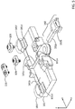
- FIG. 5 shows a partial, exploded view of the mount detailing its frame and clamp, according to an example embodiment.
- the frame 101 has a length along a first direction y, a width along a second direction x, and a height along a third direction z.
- a channel 101c is formed in a bottom surface 101b of the frame and extends along the second direction x.
- Raised pads 101d which are elevated along the third direction z with respect to the bottom surface 101b, are formed in opposite end portions A and C (see also FIG. 2 ) of the frame 101 along the first direction y.
- the raised pads 101d are disposed closer to a first edge of the frame 101 extending along the first direction y than to an opposing, second edge of the frame 101.
- a raised pad 101e which is also elevated along the third direction z with respect to the bottom surface 101b , is formed in an intermediate portion B and disposed closer to the opposing, second edge of the frame 101.
- the raised pad 101e may be disposed on opposing sides of the channel 101c.
- the frame 101 also includes hook-shaped members 101f formed in opposite end portions A and C (see also FIG. 2 ) of the frame 101 along the first direction y.
- the hook-shaped members 101f are disposed closer to the first edge of the frame 101 extending along the first direction y than to the opposing, second edge of the frame 101. More about the function and configuration of the raised pads 101d and 101e and hook-shaped members 101f is discussed later on below.
- the clamp 102 includes a guide portion 102a that is configured to be slidable in the channel 101c of the frame 101 and a hook-shaped member 102b disposed closer to the second edge of the frame 101 than to the first edge of the frame 101.
- Motion of the clamp 102 along the third direction z is constrained with respect to the frame 101 by guide brackets 109, which are secured to the frame 101 by bracket screws 111.
- the clamp 102 is slidable in the channel 101c along the second direction, its range of motion may be limited by the endplate bracket 110, which is also secured to the frame 101 by bracket screws 111.
- the endplate bracket 110 may include an endplate that prevents the clamp guide 102a from sliding and extending beyond the first edge of the frame 101.
- the clamp return spring 112 may be disposed between the endplate and an end of the clamp guide 102a to provide a return spring force that pushes the clamp 102a towards the second edge of the frame 101. More about the function and configuration of the hook-shaped member 102b and clamp return spring 112 is discussed later on below.
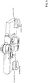
- FIG. 6 shows a cross-sectional view of the mount when assembled, according to an example embodiment.
- the clamp 102 acts as a cam follower to the lever cam 103. That is, when the lever cam 103 is rotated in one direction, it pushes the clamp 102 towards the first edge of the frame 101 along which the endplate bracket 110 is disposed.
- the lever cam 103 is configured to translate a rotary force applied thereto into a linear force applied to the clamp 102 along the second direction x.
- the lever cam 103 is rotated in the other direction, it allows the clamp 102 to retract towards the second edge of the frame 101 via a spring force provided by the return spring 112.
- the mount according to embodiments of the present disclosure provides a deterministic, or significantly more deterministic, resting position between the mount and rail by minimizing the number of intentional and unintentional contact points between the mount and the rail, thereby approaching that of a true kinematic rail mounting system.
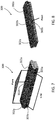
- FIGs. 7 and 8 show example contact points on the rail at which the mount makes contact, according to an embodiment.
- FIGs. 9 and 10 show example contact points on the mount that correspond to the contact points on the rail, according to an example embodiment.
- the first set of contact areas 302a and 302b on the upper portion of topmost surface 302 of the rail 300 forms a stable triangle platform (i.e., determines a primary plane) at the furthest extents of the mount, thereby restraining the system (e.g., mount +rail) in 3 degrees of freedom (DOF).
- the frame 101 only contacts the topmost surface of the rail 300 by only the raised pads 101d and 101e (refer back to FIG. 5 ).
- the contact areas 302a are contacted by the raised pads 101d of the frame 101, and the contact area 302b is contacted by the raised pad 101e of the frame 101.
- Surfaces of the raised pads 101d and 101e contacting the topmost surface 302 of the rail 300 are formed to be discontinuous with each other to minimize the size of the contact areas with the rail. These small contact areas provide a more deterministic restraining solution approaching that of a perfectly constrained system.
- a second set of contact areas 303a on the under surface 302 along one side of the rail 300 constrains the system in two more DOF (i.e., determines a line).
- the contact areas 303a are disposed adjacent to the contact areas 302a to face each other so as to reduce the degree of freedom in the system.
- the frame 101 contacts the under surface along the one side of the rail 300 by only the hook-shaped members 101f (refer back to FIG. 5 ).
- Surfaces of the hooked-shaped members 101f contacting the under surface of the rail are formed to be discontinuous with each other, rather than forming one long continuous surface, to minimize the size of the contact areas with the rail. Again, these small contact areas provide a more deterministic restraining solution approaching that of a perfectly constrained system.
- a last contact area 303b on the under surface 302 along an opposing side of the rail 300 constrains the system in another DOF (i.e., determines a point).
- the contact area 303b is disposed adjacent to the contact area 302b to face each other so as to reduce the amount of flex in the system, that is, to increase the stiffness of the system.
- the mount contacts the under surface along the opposing side of the rail 300 by only the hook-shaped member 102b (refer back to FIG. 5 ) of the clamp 102.
- the clamp 102 forces the rail 300 up against the other 5 contact areas and by friction, constrains the mount to the rail 300, thereby removing the last DOF.
- raised pads 101d and 101e, hook shaped members 101f, and/or hooked shaped member 102b of clamp 102 comprise curved (e.g., large radius spherical) surfaces where they make contact with the rail. Some, all, or any combination of these features may comprise such curved surfaces.
- the curved (e.g., spherical) contact area (or patch) between the flat surface (rail) and the curved surface (mount) becomes smaller.
- the contact patch may be sized (radius) to limit the Hertzian stresses in the material.
- the mount may be configured to make contact with the topmost surface of the rail at three points 304a and 304b located on angled edge portions 304 of topmost surface 302.
- the set of contact areas 304a and 304b forms a stable triangle platform (i.e., determines a primary plane) at the furthest extents of the mount, thereby restraining the system (e.g., mount +rail) in 3 degrees of freedom (DOF) similarly to the set of contact areas 303a and 303b shown in FIGs. 7 and 8 .
- the mount according to example embodiments disclosed herein provides an advantage over existing mounts.
- the presently disclosed mount provides a deterministic, or significantly more deterministic, resting position between the mount and rail by minimizing the number of intentional and unintentional contact points between the mount and the rail, thereby approaching that of a true kinematic mounting system that is significantly better suited for mounting a sight on a firearm.
Landscapes
- Engineering & Computer Science (AREA)
- General Engineering & Computer Science (AREA)
- Aiming, Guidance, Guns With A Light Source, Armor, Camouflage, And Targets (AREA)
- Dental Tools And Instruments Or Auxiliary Dental Instruments (AREA)
- Golf Clubs (AREA)
Claims (13)
- Kinematische Schienenhalterung (100) zur Montage eine Vorrichtung an einer Schiene (300), wobei die Schiene (300) eine oberste Fläche (302) und eine untere Fläche (303) entlang gegenüberliegenden Seiten der Schiene (300) aufweist, wobei die Halterung aufweist:einen Rahmen (101) mit einer Länge entlang einer ersten Richtung (y), einer Breite entlang einer zweiten Richtung (x) und einer Höhe entlang einer dritten Richtung (z); und eine Klemme (102), wobei die Klemme (102) mit dem Rahmen (101) wirkverbunden ist, um entlang der zweiten Richtung (x) verschieblich zu sein, der Rahmen (101) einen ersten Endabschnitt (A) und einen zweiten Endabschnitt (C), die entlang der ersten Richtung (y) angeordnet sind, und einen mittleren Abschnitt (B) der zwischen dem ersten und zweiten Endabschnitt (A, C) angeordnet ist, aufweist,dadurch gekennzeichnet, dassdie Klemme (102) eine Führung (102a) aufweist, die in einem Kanal (102C) angeordnet ist, der in dem mittleren Abschnitt (B) des Rahmens (101) gebildet ist,der erste Endabschnitt (A) und der zweite Endabschnitt (C) jeweils ein erstes erhöhtes Pad (101d) und ein zweites erhöhtes Pad (101d) aufweisen, wobei jedes erhöhte Pad (101d) näher an einer ersten Kante des Rahmens (101) als an einer zweiten Kante des Rahmens (101) angeordnet ist, wobei die erste und zweite Kante gegenüberliegende Kanten sind, die sich entlang der ersten Richtung (y) erstrecken,der mittlere Abschnitt (B) ein drittes erhöhtes Pad (101e) aufweist, das näher an der zweiten Kante des Rahmens (101) als an der ersten Kante des Rahmens (101) angeordnet ist,der Rahmen (101) eingerichtet ist, die oberste Fläche (302) der Schiene (300) nur durch das erste, zweite und dritte erhöhte Pad (101d, 101e) des Rahmens zu berühren, undeine Oberfläche des ersten erhöhten Pads (101d), das die oberste Fläche (302) der Schiene (300) berührt, eine Oberfläche des zweiten erhöhten Pads (101d), das die oberste Fläche (302) der Schiene (300) berührt, und eine Oberfläche des dritten erhöhten Pads (101e), das die oberste Fläche (302) der Schiene (300) berührt, unterbrochen voneinander sind.
- Kinematische Schienenhalterung (100) nach Anspruch 1, wobei:der erste Endabschnitt (A) und der zweite Endabschnitt (C) jeweils ein erstes hakenförmiges Element (101f) und ein zweites hakenförmiges Element (101f) aufweisen, wobei jedes hakenförmige Element (101f) näher an der ersten Kante des Rahmens (101) angeordnet ist als an der zweiten Kante des Rahmens (101), unddie Klemme (102) ein drittes hakenförmiges Element (102b) aufweist, das näher an der zweiten Kante des Rahmens (101) angeordnet ist als an der ersten Kante des Rahmens (101).
- Kinematische Schienenhalterung (100) nach Anspruch 2, wobei:der Rahmen (101) eingerichtet ist, die untere Fläche (303) entlang einer Seite der Schiene (300) nur durch das erste und zweite hakenförmige Element (101f) zu berühren; unddie Klemme (102) eingerichtet ist, die untere Fläche (303) entlang einer gegenüberliegenden Seite der Schiene (300) durch das dritte hakenförmige Element (102b) zu berühren.
- Kinematische Schienenhalterung (100) nach Anspruch 3, wobei eine Oberfläche des ersten hakenförmigen Elements (101f), das die untere Fläche (303) der Schiene (300) entlang der einen Seite berührt, unterbrochen in Bezug auf eine Oberfläche des zweiten hakenförmigen Elements (101f) ist, das die untere Fläche (303) der Schiene (300) entlang der einen Seite berührt.
- Kinematische Schienenhalterung (100) nach Anspruch 1, wobei das dritte erhöhte Pad (101e) entlang gegenüberliegender Seiten des Kanals (101c) angeordnet ist.
- Kinematische Schienenhalterung (100) nach Anspruch 3, wobei das erste erhöhte Pad (101d) und/oder das zweite erhöhte Pad (101d) und/oder das dritte erhöhte Pad (101e) und/oder das erste hakenförmige Element und/oder das zweite hakenförmige Element und/oder das dritte hakenförmige Element (102b) dort, wo es die Schiene (300) berührt, eine gewölbte Oberfläche aufweist.
- Kinematische Schienenhalterung (100) nach Anspruch 6, wobei die gewölbte Oberfläche eine Kugelform besitzt.
- Kinematische Schienenhalterung (100) nach Anspruch 3, wobei das erste erhöhte Pad (101d), das zweite erhöhte Pad (101d), das dritte erhöhte Pad (101e), das erste hakenförmige Element (101f), das zweite hakenförmige Element (101f) und das dritte hakenförmige Element (101b) dort, wo es die Schiene (300) berührt, eine gekrümmte Oberfläche aufweist.
- Kinematische Schienenhalterung (100) nach Anspruch 8, wobei die gekrümmten Oberflächen eine Kugelform besitzen.
- Kinematische Schienenhalterung (100) nach Anspruch 3, wobei das erste erhöhte Pad (101d), das zweite erhöhte Pad (101d) und das dritte erhöhte Pad (101e) dort, wo sie die Schiene (300) berühren, jeweils eine gekrümmte Oberfläche aufweisen.
- Kinematische Schienenhalterung (100) nach Anspruch 9, wobei die gekrümmten Oberflächen eine Kugelform besitzen.
- Kinematische Schienenhalterung (100) nach Anspruch 1, wobei die oberste Fläche (302) der Schiene (300) abgewinkelte Randabschnitte (304) aufweist.
- Kinematische Schienenhalterung (100) nach Anspruch 12, wobei der Rahmen (101) eingerichtet ist, die oberste Fläche (302) der Schiene (300) lediglich durch das erste, das zweite und das dritte erhöhte Pad (101d, 101e) des Rahmens (101) zu berühren, und nur an den abgewinkelten Randabschnitten (304) der obersten Fläche (302).
Applications Claiming Priority (1)
| Application Number | Priority Date | Filing Date | Title |
|---|---|---|---|
| US201762510139P | 2017-05-23 | 2017-05-23 |
Publications (2)
| Publication Number | Publication Date |
|---|---|
| EP3407005A1 EP3407005A1 (de) | 2018-11-28 |
| EP3407005B1 true EP3407005B1 (de) | 2020-04-08 |
Family
ID=62222505
Family Applications (1)
| Application Number | Title | Priority Date | Filing Date |
|---|---|---|---|
| EP18173573.9A Active EP3407005B1 (de) | 2017-05-23 | 2018-05-22 | Kinematische schienenhalterung zur montage einer vorrichtung an einer schusswaffenschiene |
Country Status (2)
| Country | Link |
|---|---|
| US (1) | US10443985B2 (de) |
| EP (1) | EP3407005B1 (de) |
Families Citing this family (10)
| Publication number | Priority date | Publication date | Assignee | Title |
|---|---|---|---|---|
| US10690449B2 (en) * | 2017-05-23 | 2020-06-23 | Steiner Eoptics, Inc. | Kinematic rail mount for mounting a device on a firearm rail |
| US10557487B2 (en) * | 2018-02-12 | 2020-02-11 | Mark C. LaRue | Lever-actuated firearm accessory mount having tool-less clamp adjustment |
| US11541269B2 (en) * | 2019-06-11 | 2023-01-03 | Coulter Ventures, Llc. | Weight rack and mounting rail, accessory, and assembly for weight rack |
| US11543212B1 (en) * | 2019-11-22 | 2023-01-03 | Phillip Letts | Indexing scope mount assembly |
| CN111664424B (zh) * | 2020-05-18 | 2022-10-11 | 深圳市傲雷电商科技股份有限公司 | 一种手枪枪灯的快拆装置 |
| CN213097434U (zh) * | 2020-05-18 | 2021-05-04 | 王金友 | 一种可伸缩的电动窗帘轨道和电动窗帘 |
| US11585620B2 (en) * | 2020-08-09 | 2023-02-21 | Zrodelta, Llc | Mount for a firearm |
| CN216385278U (zh) * | 2022-01-12 | 2022-04-26 | 深圳市鑫玥涵科技有限公司 | 一种可以移动的限位快拆枪灯 |
| USD974519S1 (en) * | 2022-10-31 | 2023-01-03 | Fu LIU | Rail mount |
| US20260069912A1 (en) * | 2024-09-10 | 2026-03-12 | BodyKore, Inc. | Mounting system for attachment of interchangeable exercise machine accessories |
Family Cites Families (9)
| Publication number | Priority date | Publication date | Assignee | Title |
|---|---|---|---|---|
| US5806228A (en) * | 1996-11-12 | 1998-09-15 | Martel; Phillip C. | Scope mount for the carrying handle of M-16 type rifles |
| US7685759B2 (en) | 2006-11-01 | 2010-03-30 | Wilcox Industries Corp. | Three-point clamp for firearm mounting rail |
| US7712242B2 (en) | 2006-12-27 | 2010-05-11 | Surefire, Llc | Rail clamp mount |
| US8931161B2 (en) | 2009-08-05 | 2015-01-13 | Eric D. Couture | Rail attachment mechanism |
| US8572885B2 (en) * | 2010-01-12 | 2013-11-05 | Theodore Karagias | Mounting clamps for coupling scopes to mounting rails of firearms |
| US8393105B1 (en) | 2010-04-29 | 2013-03-12 | Laser Devices, Inc. | Floating side rail clamp weapon accessory mount adaptor |
| EP3064823B1 (de) * | 2015-03-04 | 2017-09-27 | vhf elektronik GmbH | Schnellspannvorrichtung zur selbstschliessenden aufnahme eines gegegenstücks |
| KR101597953B1 (ko) * | 2015-08-12 | 2016-02-25 | 임홍규 | 레일 마운트 |
| US10030940B2 (en) * | 2016-01-15 | 2018-07-24 | Sig Sauer, Inc. | Firearm accessory attachment clamp |
-
2018
- 2018-05-21 US US15/984,957 patent/US10443985B2/en not_active Expired - Fee Related
- 2018-05-22 EP EP18173573.9A patent/EP3407005B1/de active Active
Non-Patent Citations (1)
| Title |
|---|
| None * |
Also Published As
| Publication number | Publication date |
|---|---|
| US20180340755A1 (en) | 2018-11-29 |
| US10443985B2 (en) | 2019-10-15 |
| EP3407005A1 (de) | 2018-11-28 |
Similar Documents
| Publication | Publication Date | Title |
|---|---|---|
| US10443985B2 (en) | Kinematic rail mount for mounting a device on a firearm rail | |
| EP3407006B1 (de) | Kinematische schienenhalterung zur montage einer vorrichtung an einer schusswaffenschiene | |
| US20250334377A1 (en) | Mounts for optical sighting devices | |
| US8499485B2 (en) | Sliding mount adapter device | |
| US8393105B1 (en) | Floating side rail clamp weapon accessory mount adaptor | |
| US9494382B2 (en) | Firearm hand guard mounting assembly | |
| US5430967A (en) | Aiming assistance device for a weapon | |
| US8572885B2 (en) | Mounting clamps for coupling scopes to mounting rails of firearms | |
| US9664479B1 (en) | Adjustable firearm stock | |
| US9568282B1 (en) | Apparatus for securely mounting accessories to a camera or firearm | |
| US8667727B2 (en) | Device for mounting an additional device to a firearm | |
| US9664476B1 (en) | Adjustable firearm stock | |
| RU2452915C2 (ru) | Устройство для закрепления дополнительной детали на оружии | |
| US10041765B2 (en) | Creep preventing scope mount system | |
| US8276307B2 (en) | Mount adapter device utilizing a push system | |
| US20160341523A1 (en) | Modular rail system and firearm with modular rail system | |
| US20180195838A1 (en) | Firearm accessory interchangeable mount system | |
| US9581416B1 (en) | Rail mount | |
| US20090038201A1 (en) | Gun attachment mounting structure | |
| US8407923B2 (en) | Systems and methods for associating an accessory with a firearm | |
| DE69811480D1 (de) | Zielfernrohr für individuelle waffe mit automatischem richten und einstellen | |
| EP3406919B1 (de) | Verriegelung und anordnung damit | |
| US12140405B2 (en) | Device for attaching a sight to a handgun | |
| US20130008071A1 (en) | Mounting device having an additional stopp | |
| US11162518B1 (en) | Rail clamp assembly |
Legal Events
| Date | Code | Title | Description |
|---|---|---|---|
| PUAI | Public reference made under article 153(3) epc to a published international application that has entered the european phase |
Free format text: ORIGINAL CODE: 0009012 |
|
| STAA | Information on the status of an ep patent application or granted ep patent |
Free format text: STATUS: THE APPLICATION HAS BEEN PUBLISHED |
|
| AK | Designated contracting states |
Kind code of ref document: A1 Designated state(s): AL AT BE BG CH CY CZ DE DK EE ES FI FR GB GR HR HU IE IS IT LI LT LU LV MC MK MT NL NO PL PT RO RS SE SI SK SM TR |
|
| AX | Request for extension of the european patent |
Extension state: BA ME |
|
| STAA | Information on the status of an ep patent application or granted ep patent |
Free format text: STATUS: REQUEST FOR EXAMINATION WAS MADE |
|
| 17P | Request for examination filed |
Effective date: 20190528 |
|
| RBV | Designated contracting states (corrected) |
Designated state(s): AL AT BE BG CH CY CZ DE DK EE ES FI FR GB GR HR HU IE IS IT LI LT LU LV MC MK MT NL NO PL PT RO RS SE SI SK SM TR |
|
| RIN1 | Information on inventor provided before grant (corrected) |
Inventor name: COSENTINO, TIMOTHY J. |
|
| GRAP | Despatch of communication of intention to grant a patent |
Free format text: ORIGINAL CODE: EPIDOSNIGR1 |
|
| STAA | Information on the status of an ep patent application or granted ep patent |
Free format text: STATUS: GRANT OF PATENT IS INTENDED |
|
| RIC1 | Information provided on ipc code assigned before grant |
Ipc: F41G 11/00 20060101AFI20191003BHEP |
|
| INTG | Intention to grant announced |
Effective date: 20191104 |
|
| GRAS | Grant fee paid |
Free format text: ORIGINAL CODE: EPIDOSNIGR3 |
|
| GRAA | (expected) grant |
Free format text: ORIGINAL CODE: 0009210 |
|
| STAA | Information on the status of an ep patent application or granted ep patent |
Free format text: STATUS: THE PATENT HAS BEEN GRANTED |
|
| AK | Designated contracting states |
Kind code of ref document: B1 Designated state(s): AL AT BE BG CH CY CZ DE DK EE ES FI FR GB GR HR HU IE IS IT LI LT LU LV MC MK MT NL NO PL PT RO RS SE SI SK SM TR |
|
| REG | Reference to a national code |
Ref country code: CH Ref legal event code: EP Ref country code: AT Ref legal event code: REF Ref document number: 1254964 Country of ref document: AT Kind code of ref document: T Effective date: 20200415 |
|
| REG | Reference to a national code |
Ref country code: DE Ref legal event code: R096 Ref document number: 602018003540 Country of ref document: DE |
|
| REG | Reference to a national code |
Ref country code: IE Ref legal event code: FG4D |
|
| REG | Reference to a national code |
Ref country code: NL Ref legal event code: MP Effective date: 20200408 |
|
| REG | Reference to a national code |
Ref country code: LT Ref legal event code: MG4D |
|
| PG25 | Lapsed in a contracting state [announced via postgrant information from national office to epo] |
Ref country code: LT Free format text: LAPSE BECAUSE OF FAILURE TO SUBMIT A TRANSLATION OF THE DESCRIPTION OR TO PAY THE FEE WITHIN THE PRESCRIBED TIME-LIMIT Effective date: 20200408 Ref country code: FI Free format text: LAPSE BECAUSE OF FAILURE TO SUBMIT A TRANSLATION OF THE DESCRIPTION OR TO PAY THE FEE WITHIN THE PRESCRIBED TIME-LIMIT Effective date: 20200408 Ref country code: GR Free format text: LAPSE BECAUSE OF FAILURE TO SUBMIT A TRANSLATION OF THE DESCRIPTION OR TO PAY THE FEE WITHIN THE PRESCRIBED TIME-LIMIT Effective date: 20200709 Ref country code: NO Free format text: LAPSE BECAUSE OF FAILURE TO SUBMIT A TRANSLATION OF THE DESCRIPTION OR TO PAY THE FEE WITHIN THE PRESCRIBED TIME-LIMIT Effective date: 20200708 Ref country code: SE Free format text: LAPSE BECAUSE OF FAILURE TO SUBMIT A TRANSLATION OF THE DESCRIPTION OR TO PAY THE FEE WITHIN THE PRESCRIBED TIME-LIMIT Effective date: 20200408 Ref country code: IS Free format text: LAPSE BECAUSE OF FAILURE TO SUBMIT A TRANSLATION OF THE DESCRIPTION OR TO PAY THE FEE WITHIN THE PRESCRIBED TIME-LIMIT Effective date: 20200808 Ref country code: PT Free format text: LAPSE BECAUSE OF FAILURE TO SUBMIT A TRANSLATION OF THE DESCRIPTION OR TO PAY THE FEE WITHIN THE PRESCRIBED TIME-LIMIT Effective date: 20200817 Ref country code: NL Free format text: LAPSE BECAUSE OF FAILURE TO SUBMIT A TRANSLATION OF THE DESCRIPTION OR TO PAY THE FEE WITHIN THE PRESCRIBED TIME-LIMIT Effective date: 20200408 |
|
| REG | Reference to a national code |
Ref country code: AT Ref legal event code: MK05 Ref document number: 1254964 Country of ref document: AT Kind code of ref document: T Effective date: 20200408 |
|
| PG25 | Lapsed in a contracting state [announced via postgrant information from national office to epo] |
Ref country code: RS Free format text: LAPSE BECAUSE OF FAILURE TO SUBMIT A TRANSLATION OF THE DESCRIPTION OR TO PAY THE FEE WITHIN THE PRESCRIBED TIME-LIMIT Effective date: 20200408 Ref country code: LV Free format text: LAPSE BECAUSE OF FAILURE TO SUBMIT A TRANSLATION OF THE DESCRIPTION OR TO PAY THE FEE WITHIN THE PRESCRIBED TIME-LIMIT Effective date: 20200408 Ref country code: HR Free format text: LAPSE BECAUSE OF FAILURE TO SUBMIT A TRANSLATION OF THE DESCRIPTION OR TO PAY THE FEE WITHIN THE PRESCRIBED TIME-LIMIT Effective date: 20200408 Ref country code: BG Free format text: LAPSE BECAUSE OF FAILURE TO SUBMIT A TRANSLATION OF THE DESCRIPTION OR TO PAY THE FEE WITHIN THE PRESCRIBED TIME-LIMIT Effective date: 20200708 |
|
| PG25 | Lapsed in a contracting state [announced via postgrant information from national office to epo] |
Ref country code: AL Free format text: LAPSE BECAUSE OF FAILURE TO SUBMIT A TRANSLATION OF THE DESCRIPTION OR TO PAY THE FEE WITHIN THE PRESCRIBED TIME-LIMIT Effective date: 20200408 |
|
| REG | Reference to a national code |
Ref country code: DE Ref legal event code: R097 Ref document number: 602018003540 Country of ref document: DE |
|
| PG25 | Lapsed in a contracting state [announced via postgrant information from national office to epo] |
Ref country code: CZ Free format text: LAPSE BECAUSE OF FAILURE TO SUBMIT A TRANSLATION OF THE DESCRIPTION OR TO PAY THE FEE WITHIN THE PRESCRIBED TIME-LIMIT Effective date: 20200408 Ref country code: RO Free format text: LAPSE BECAUSE OF FAILURE TO SUBMIT A TRANSLATION OF THE DESCRIPTION OR TO PAY THE FEE WITHIN THE PRESCRIBED TIME-LIMIT Effective date: 20200408 Ref country code: MC Free format text: LAPSE BECAUSE OF FAILURE TO SUBMIT A TRANSLATION OF THE DESCRIPTION OR TO PAY THE FEE WITHIN THE PRESCRIBED TIME-LIMIT Effective date: 20200408 Ref country code: DK Free format text: LAPSE BECAUSE OF FAILURE TO SUBMIT A TRANSLATION OF THE DESCRIPTION OR TO PAY THE FEE WITHIN THE PRESCRIBED TIME-LIMIT Effective date: 20200408 Ref country code: SM Free format text: LAPSE BECAUSE OF FAILURE TO SUBMIT A TRANSLATION OF THE DESCRIPTION OR TO PAY THE FEE WITHIN THE PRESCRIBED TIME-LIMIT Effective date: 20200408 Ref country code: EE Free format text: LAPSE BECAUSE OF FAILURE TO SUBMIT A TRANSLATION OF THE DESCRIPTION OR TO PAY THE FEE WITHIN THE PRESCRIBED TIME-LIMIT Effective date: 20200408 Ref country code: AT Free format text: LAPSE BECAUSE OF FAILURE TO SUBMIT A TRANSLATION OF THE DESCRIPTION OR TO PAY THE FEE WITHIN THE PRESCRIBED TIME-LIMIT Effective date: 20200408 Ref country code: ES Free format text: LAPSE BECAUSE OF FAILURE TO SUBMIT A TRANSLATION OF THE DESCRIPTION OR TO PAY THE FEE WITHIN THE PRESCRIBED TIME-LIMIT Effective date: 20200408 |
|
| PLBE | No opposition filed within time limit |
Free format text: ORIGINAL CODE: 0009261 |
|
| STAA | Information on the status of an ep patent application or granted ep patent |
Free format text: STATUS: NO OPPOSITION FILED WITHIN TIME LIMIT |
|
| PG25 | Lapsed in a contracting state [announced via postgrant information from national office to epo] |
Ref country code: SK Free format text: LAPSE BECAUSE OF FAILURE TO SUBMIT A TRANSLATION OF THE DESCRIPTION OR TO PAY THE FEE WITHIN THE PRESCRIBED TIME-LIMIT Effective date: 20200408 Ref country code: PL Free format text: LAPSE BECAUSE OF FAILURE TO SUBMIT A TRANSLATION OF THE DESCRIPTION OR TO PAY THE FEE WITHIN THE PRESCRIBED TIME-LIMIT Effective date: 20200408 |
|
| 26N | No opposition filed |
Effective date: 20210112 |
|
| REG | Reference to a national code |
Ref country code: BE Ref legal event code: MM Effective date: 20200531 |
|
| PG25 | Lapsed in a contracting state [announced via postgrant information from national office to epo] |
Ref country code: LU Free format text: LAPSE BECAUSE OF NON-PAYMENT OF DUE FEES Effective date: 20200522 |
|
| PG25 | Lapsed in a contracting state [announced via postgrant information from national office to epo] |
Ref country code: IE Free format text: LAPSE BECAUSE OF NON-PAYMENT OF DUE FEES Effective date: 20200522 |
|
| PG25 | Lapsed in a contracting state [announced via postgrant information from national office to epo] |
Ref country code: BE Free format text: LAPSE BECAUSE OF NON-PAYMENT OF DUE FEES Effective date: 20200531 Ref country code: SI Free format text: LAPSE BECAUSE OF FAILURE TO SUBMIT A TRANSLATION OF THE DESCRIPTION OR TO PAY THE FEE WITHIN THE PRESCRIBED TIME-LIMIT Effective date: 20200408 |
|
| REG | Reference to a national code |
Ref country code: CH Ref legal event code: PL |
|
| PG25 | Lapsed in a contracting state [announced via postgrant information from national office to epo] |
Ref country code: CH Free format text: LAPSE BECAUSE OF NON-PAYMENT OF DUE FEES Effective date: 20210531 Ref country code: LI Free format text: LAPSE BECAUSE OF NON-PAYMENT OF DUE FEES Effective date: 20210531 |
|
| PG25 | Lapsed in a contracting state [announced via postgrant information from national office to epo] |
Ref country code: TR Free format text: LAPSE BECAUSE OF FAILURE TO SUBMIT A TRANSLATION OF THE DESCRIPTION OR TO PAY THE FEE WITHIN THE PRESCRIBED TIME-LIMIT Effective date: 20200408 Ref country code: MT Free format text: LAPSE BECAUSE OF FAILURE TO SUBMIT A TRANSLATION OF THE DESCRIPTION OR TO PAY THE FEE WITHIN THE PRESCRIBED TIME-LIMIT Effective date: 20200408 Ref country code: CY Free format text: LAPSE BECAUSE OF FAILURE TO SUBMIT A TRANSLATION OF THE DESCRIPTION OR TO PAY THE FEE WITHIN THE PRESCRIBED TIME-LIMIT Effective date: 20200408 |
|
| PG25 | Lapsed in a contracting state [announced via postgrant information from national office to epo] |
Ref country code: MK Free format text: LAPSE BECAUSE OF FAILURE TO SUBMIT A TRANSLATION OF THE DESCRIPTION OR TO PAY THE FEE WITHIN THE PRESCRIBED TIME-LIMIT Effective date: 20200408 |
|
| PGFP | Annual fee paid to national office [announced via postgrant information from national office to epo] |
Ref country code: IT Payment date: 20220531 Year of fee payment: 5 Ref country code: GB Payment date: 20220523 Year of fee payment: 5 Ref country code: FR Payment date: 20220523 Year of fee payment: 5 |
|
| P01 | Opt-out of the competence of the unified patent court (upc) registered |
Effective date: 20230517 |
|
| PGFP | Annual fee paid to national office [announced via postgrant information from national office to epo] |
Ref country code: DE Payment date: 20230524 Year of fee payment: 6 |
|
| GBPC | Gb: european patent ceased through non-payment of renewal fee |
Effective date: 20230522 |
|
| PG25 | Lapsed in a contracting state [announced via postgrant information from national office to epo] |
Ref country code: IT Free format text: LAPSE BECAUSE OF NON-PAYMENT OF DUE FEES Effective date: 20230522 Ref country code: GB Free format text: LAPSE BECAUSE OF NON-PAYMENT OF DUE FEES Effective date: 20230522 |
|
| PG25 | Lapsed in a contracting state [announced via postgrant information from national office to epo] |
Ref country code: FR Free format text: LAPSE BECAUSE OF NON-PAYMENT OF DUE FEES Effective date: 20230531 |
|
| REG | Reference to a national code |
Ref country code: DE Ref legal event code: R119 Ref document number: 602018003540 Country of ref document: DE |
|
| PG25 | Lapsed in a contracting state [announced via postgrant information from national office to epo] |
Ref country code: DE Free format text: LAPSE BECAUSE OF NON-PAYMENT OF DUE FEES Effective date: 20241203 |