EP3460760B1 - Generating a 2d drawing representing a mechanical part - Google Patents
Generating a 2d drawing representing a mechanical part Download PDFInfo
- Publication number
- EP3460760B1 EP3460760B1 EP17306268.8A EP17306268A EP3460760B1 EP 3460760 B1 EP3460760 B1 EP 3460760B1 EP 17306268 A EP17306268 A EP 17306268A EP 3460760 B1 EP3460760 B1 EP 3460760B1
- Authority
- EP
- European Patent Office
- Prior art keywords
- curves
- curvature
- continuous
- edges
- curve
- Prior art date
- Legal status (The legal status is an assumption and is not a legal conclusion. Google has not performed a legal analysis and makes no representation as to the accuracy of the status listed.)
- Active
Links
- 238000000034 method Methods 0.000 claims description 90
- 238000004519 manufacturing process Methods 0.000 claims description 40
- 230000000007 visual effect Effects 0.000 claims description 30
- 230000008569 process Effects 0.000 claims description 19
- 239000002184 metal Substances 0.000 claims description 12
- 238000004590 computer program Methods 0.000 claims description 10
- 230000006870 function Effects 0.000 claims description 6
- 238000003860 storage Methods 0.000 claims description 5
- 238000005266 casting Methods 0.000 claims description 4
- 239000013598 vector Substances 0.000 description 11
- 238000013461 design Methods 0.000 description 8
- 239000000463 material Substances 0.000 description 4
- 230000006399 behavior Effects 0.000 description 3
- 238000004140 cleaning Methods 0.000 description 3
- 238000011960 computer-aided design Methods 0.000 description 3
- 238000007726 management method Methods 0.000 description 3
- 238000013507 mapping Methods 0.000 description 3
- 239000007787 solid Substances 0.000 description 3
- 238000004458 analytical method Methods 0.000 description 2
- 238000004891 communication Methods 0.000 description 2
- 238000013500 data storage Methods 0.000 description 2
- 230000006872 improvement Effects 0.000 description 2
- 230000003993 interaction Effects 0.000 description 2
- 238000004806 packaging method and process Methods 0.000 description 2
- 238000012545 processing Methods 0.000 description 2
- 239000004065 semiconductor Substances 0.000 description 2
- 238000004088 simulation Methods 0.000 description 2
- 238000012360 testing method Methods 0.000 description 2
- 206010003830 Automatism Diseases 0.000 description 1
- 241000208125 Nicotiana Species 0.000 description 1
- 235000002637 Nicotiana tabacum Nutrition 0.000 description 1
- 230000000712 assembly Effects 0.000 description 1
- 238000000429 assembly Methods 0.000 description 1
- 230000003796 beauty Effects 0.000 description 1
- 230000008901 benefit Effects 0.000 description 1
- 235000013361 beverage Nutrition 0.000 description 1
- 238000004364 calculation method Methods 0.000 description 1
- 230000008859 change Effects 0.000 description 1
- 238000010276 construction Methods 0.000 description 1
- 238000013523 data management Methods 0.000 description 1
- 230000007123 defense Effects 0.000 description 1
- 238000011161 development Methods 0.000 description 1
- 238000005553 drilling Methods 0.000 description 1
- 235000013305 food Nutrition 0.000 description 1
- 230000007274 generation of a signal involved in cell-cell signaling Effects 0.000 description 1
- 230000010354 integration Effects 0.000 description 1
- 230000007246 mechanism Effects 0.000 description 1
- 238000003801 milling Methods 0.000 description 1
- 230000008450 motivation Effects 0.000 description 1
- 230000003287 optical effect Effects 0.000 description 1
- 238000005457 optimization Methods 0.000 description 1
- 238000002360 preparation method Methods 0.000 description 1
- 238000004080 punching Methods 0.000 description 1
- 238000010200 validation analysis Methods 0.000 description 1
- 238000012800 visualization Methods 0.000 description 1
Images


Classifications
-
- G—PHYSICS
- G06—COMPUTING; CALCULATING OR COUNTING
- G06T—IMAGE DATA PROCESSING OR GENERATION, IN GENERAL
- G06T15/00—3D [Three Dimensional] image rendering
- G06T15/10—Geometric effects
-
- G—PHYSICS
- G06—COMPUTING; CALCULATING OR COUNTING
- G06F—ELECTRIC DIGITAL DATA PROCESSING
- G06F30/00—Computer-aided design [CAD]
- G06F30/10—Geometric CAD
- G06F30/17—Mechanical parametric or variational design
-
- G—PHYSICS
- G06—COMPUTING; CALCULATING OR COUNTING
- G06T—IMAGE DATA PROCESSING OR GENERATION, IN GENERAL
- G06T15/00—3D [Three Dimensional] image rendering
- G06T15/10—Geometric effects
- G06T15/20—Perspective computation
-
- G—PHYSICS
- G06—COMPUTING; CALCULATING OR COUNTING
- G06T—IMAGE DATA PROCESSING OR GENERATION, IN GENERAL
- G06T17/00—Three dimensional [3D] modelling, e.g. data description of 3D objects
- G06T17/10—Constructive solid geometry [CSG] using solid primitives, e.g. cylinders, cubes
-
- G—PHYSICS
- G06—COMPUTING; CALCULATING OR COUNTING
- G06T—IMAGE DATA PROCESSING OR GENERATION, IN GENERAL
- G06T17/00—Three dimensional [3D] modelling, e.g. data description of 3D objects
- G06T17/30—Polynomial surface description
-
- G06T3/06—
-
- G06T3/067—
-
- G—PHYSICS
- G06—COMPUTING; CALCULATING OR COUNTING
- G06T—IMAGE DATA PROCESSING OR GENERATION, IN GENERAL
- G06T2215/00—Indexing scheme for image rendering
- G06T2215/06—Curved planar reformation of 3D line structures
Definitions
- the invention relates to the field of computer programs and systems, and more specifically to a method, system and program for generating a 2D drawing representing a mechanical part.
- CAD Computer-Aided Design
- CAE Computer-Aided Engineering
- CAM Computer-Aided Manufacturing
- the graphical user interface plays an important role as regards the efficiency of the technique.
- PLM refers to a business strategy that helps companies to share product data, apply common processes, and leverage corporate knowledge for the development of products from conception to the end of their life, across the concept of extended enterprise.
- the PLM solutions provided by Dassault Systèmes (under the trademarks CATIA, ENOVIA and DELMIA) provide an Engineering Hub, which organizes product engineering knowledge, a Manufacturing Hub, which manages manufacturing engineering knowledge, and an Enterprise Hub which enables enterprise integrations and connections into both the Engineering and Manufacturing Hubs. All together the system delivers an open object model linking products, processes, resources to enable dynamic, knowledge-based product creation and decision support that drives optimized product definition, manufacturing preparation, production and service.
- Such systems may include engineering 2D drawing solutions.
- a goal of engineering 2D drawing may be to provide the user with a 2D drawing made of lines, arrows, numbers and texts in order to describe the shape of a mechanical part.
- the syntax of this description is provided by well-known standards (ISO, ANSI, JIS, BS, AA, DIN).
- the art of engineering drawing is to end with a non-ambiguous and non-redundant description of the mechanical part
- Document Catia Tricks:"Surface Area of a Projection", dated 17-07-2017, pages 1-18 discloses a method of obtaining the 2D projection of a 3D model.
- a computer-implemented method for generating a 2D drawing representing a mechanical part.
- the method comprises providing a 3D modeled object which represents a 3D shape of the mechanical part, determining continuous 3D curves, and projecting the determined continuous 3D curves on a 2D plane.
- Such a method allows generating a 2D drawing representing a mechanical part from a 3D modeled object which represents a 3D shape of the mechanical part.
- the continuous 3D curves may each represent a respective instance of a predetermined set of visual characteristics of reflection lines defined on the 3D shape. This allows generating a 2D drawing which represents reflection information, and thus represents and/or allows understanding 3D shape of the mechanical part.
- the predetermined set of visual characteristics may include any one or any combination of: an end, a zero-order discontinuity, a tangent discontinuity, a curvature above a predetermined threshold, and/or a boundary of a portion including a curvature above a predetermined threshold.
- the continuous 3D curves may be defined on the 3D shape, and include one or more silhouette curves (e.g. which may each comprise one or more continuous 3D curve pieces, e.g. one or more silhouette curves being piecewise continuous) and/or any one or any combination of the following types of curves with respect to the surface of the 3D shape: singular curves - e.g. including sharp curves such as boundary curves (if the surface is an open surface) and/or (surface) tangent discontinuity curves, and/or including non-sharp singular curves (surface) such as tangent continuity but (surface) curvature discontinuity curves -, and/or smooth curves - i.e. non-sharp curves, e.g.
- singular curves e.g. including sharp curves such as boundary curves (if the surface is an open surface) and/or (surface) tangent discontinuity curves, and/or including non-sharp singular curves (surface) such as tangent continuity but (surface) cur
- the predetermined criterion may for example constitute a requirement that local (surface) curvature variation be relatively high and/or above a predetermined threshold.
- Local curvature variation may be curvature variation across the curve or in a portion bounded by the curve. This allows generating a 2D drawing which represents and/or allows understanding 3D shape of the mechanical part in a simple manner.
- 3D surface geometry may correspond to light reflection such that:
- the determined continuous 3D curves thus represent reflection information.
- the 3D modeled object may be a boundary representation (B-Rep) comprising edges.
- the B-Rep may have been designed by a designer.
- at least part of the continuous 3D curves determined to be projected may be determined among the edges of the B-Rep. This allows a simple determination of 3D curves, for example simply consisting in a selection of edges of the B-Rep.
- Said at least part of the continuous 3D curves may comprise all the determined curves but the silhouette curve(s), and/or said at least part of the continuous 3D curves may comprise all the determined curves 3D curves which represent a zero-order discontinuity of reflection lines, a tangent discontinuity of reflection lines, a curvature of reflection lines above the predetermined threshold and/or the boundaries of a portion of reflections lines including a curvature above the predetermined threshold.
- the designer may have designed the B-Rep, including adding edges to represent such visual characteristics of reflection lines, e.g. at least one B-Rep edge per instance of any of such visual characteristics. This may have allowed an efficient and natural designing for the designer. In such cases, the method may take advantage of this fact to efficiently perform the determining of the continuous 3D curves, by making use of available edges representing reflection information.
- not all the edges of the B-Rep are selected. This allows reducing the risk of superfluous 2D lines in the generated 2D drawing.
- all sharp edges-e.g. including all boundary edges (if the B-Rep is an open skin) and all tangent discontinuity edges -, and optionally all other singular but non-sharp edges such as all tangent continuity but curvature discontinuity edges - may be selected.
- non-sharp (i.e. smooth) edges may also be selected (i.e. among curvature continuity edges and optionally among curvature discontinuity but tangent continuity edges), but not all of them such that not all edges of the B-Rep are selected.
- the smooth edges which are selected may be limited to those that respect the predetermined criterion related to local curvature variation. In other words, smooth edges not respecting the predetermined criterion are not selected. This allows simply and efficiently generating a 2D drawing forming a non-ambiguous and non-redundant description of the mechanical part, with no or few superfluous 2D lines in the result.
- the method may comprise one or more of the following:
- a system comprising a processor coupled to a memory and a graphical user interface, the memory having recorded thereon the computer program.
- the method comprises providing S10 a three-dimensional (3D) modeled object.
- the 3D modeled object represents a 3D shape of the mechanical part, for example its outer surface (or skin) or its occupancy volume.
- the method also comprises determining S20 continuous 3D curves.
- Each continuous 3D curve represents a respective instance of a predetermined set of visual characteristics of reflection lines, which reflection lines are defined on the 3D shape.
- each continuous 3D curve represents a respective occurrence of one of the predetermined set.
- the continuous 3D curves are thus located on the 3D shape, e.g. on the outer surface of the mechanical part.
- the method also comprises projecting S30 the continuous 3D curves determined at S20 on a 2D plane.
- the projecting S30 may be started after the determining S20 is completely over, or alternatively the projecting S30 and the determining S20 may be interlaced.
- Such a method provides an improved solution to generate a 2D drawing representing a mechanical part.
- the method generates a 2D drawing from a 3D modeled object representing the mechanical part.
- the method bridges 3D design with engineering 2D drawing.
- This is thanks to a projection on a 2D plane of continuous 3D curves corresponding to the 3D modeled object.
- the projection of the continuous 3D curves results in 2D lines which may form at least part of the 2D drawing.
- the generated 2D lines indeed form a 2D view of the mechanical part.
- the method thereby falls within the field of 3D CAD and allows outputting a 2D drawing after a 3D modeled object of the mechanical part is provided, for example after it has been designed e.g. using a 3D CAD software.
- each continuous 3D curve represents a visual characteristic of reflection lines
- the 2D lines also represent such visual characteristics of reflection lines.
- the 2D drawing generated by the method thereby provides reflection information, thus providing visual information on the 3D shape of the mechanical part, e.g. representing 3D shape of the mechanical part in a 2D view, e.g. even without any shading, texturing, and/or photorealistic image.
- the method may comprise after or in parallel to the projection S30 addition of elements to the 2D drawing (other than the 2D lines representing characteristics of reflection lines).
- additional elements may include standard features, such as dimensions, border lines, title block, arrows, numbers and/or texts.
- the 2D drawing may be such that it does not comprise any advanced graphic feature, such as shading, texturing, or photorealistic image.
- the 2D drawing may consist of only black lines on a white background.
- the 2D drawing may meet any one or any combination of the following well-known standards: ISO, ANSI, JIS, BS, AA, and/or DIN.
- FIG. 2 shows an example of such a 2D drawing of a mechanical part, which may be outputted by the method.
- the projection S30 may be performed according to any perspective.
- the perspective comprises information providing location of the 2D plane and viewpoint (i.e. observer's position).
- the perspective may for example be a conical perspective or a cylindrical perspective.
- the 2D plane may be apart from the 3D modeled object, i.e. with no intersection between the 3D shape and the 2D plane.
- the projection S30 may for example correspond to any one of a: left, right, top, bottom, or axonometric 2D view, e.g. with respect to a reference frame associated to the 3D modeled object.
- the method may be repeated with different projections S30 so as to result in a multi-view 2D drawing of the mechanical part.
- the multi-view 2D drawing may represent the geometry of the mechanical part according to a predetermined set of viewpoints.
- the method may comprise removing geometry of the 3D modeled object hidden in the perspective.
- the removal may be performed before, at the time of or after the projecting S30, e.g. and/or before, at the time of or after the determining S20.
- the determining S20 may be performed within visible geometry only, that is within reflection lines visible in the perspective. All continuous 3D curves determining at S20 may in such a case be visible ones.
- the input of the removal may be the 3D modeled object and the perspective definition (i.e. including observer's position).
- the purpose of the removal may include eliminating geometry that is hidden to the observer.
- FIG. 3 illustrates a conical perspective of a 3D modeled object.
- FIG. 4 illustrates a cylindrical perspective of 3D modeled object.
- a reflection line defined on a 3D shape of a mechanical part is a line defined on the outer surface of the mechanical part and which represents, relative to a viewpoint, the reflect of a light source forming a straight line.
- the light source line is a line of positions from which light is emitted and which may be finite or infinite.
- the Descartes optical principle states that, firstly, the cosine of angle between vectors L - S and N is the same as the cosine of angle between vectors Q - S and N and, secondly, that the three vectors L - S, Q - S and N are coplanar, as illustrated in FIG. 5 .
- the set of reflection lines considered at S20 may comprise or consist of any set of reflection lines defined on the 3D shape.
- the set of reflection lines may for example comprise or consist of a set of reflection lines visible in the perspective according to which projection S30 is performed.
- Said set of reflection lines visible in said perspective may comprise or consist of part or all reflection lines defined relative to the perspective's viewpoint and corresponding to infinite light source lines.
- the continuous 3D curves determined at S20 represent visual characteristics of reflection lines.
- each point of a respective continuous 3D curve represents, for one or more respective reflection lines (e.g. all reflection lines that pass by the point), occurrence of the visual characteristic instance represented by the respective continuous 3D curve.
- the 3D modeled object represents a 3D shape of a mechanical part, and reflection lines present corresponding visual characteristics e.g. according to geometrical specificities of the 3D shape.
- the set of all reflection lines forms a network of lines defined all over the 3D shape. Due to material continuity, neighboring reflection lines of the network tend to present the same visual characteristics at neighboring locations. This is because reflection is a physical and material-wise continuous phenomenon.
- each visual characteristic instance across the reflections lines of the network presenting said instance corresponds to a continuous 3D curve defined on the 3D shape.
- the determining S20 need not necessarily determine reflection lines, as long as the correct continuous 3D curves are provided to the projecting S30. In the examples discussed later, the method actually does not determine any reflection line, but merely perform geometrical computations to determine S20 directly the continuous 3D curves.
- a visual characteristic of a reflection line is any position of the reflection line visually identifiable, i.e. a visual singularity point of the reflection line.
- said visual characteristics form 3D continuous curves visually identifiable.
- the method determines S20 said 3D continuous curves to project S30 them, making the 2D drawing representative of 3D shape.
- the predetermined set of visual characteristics may for example comprise or consist of any one or any combination (e.g. including at least the end characteristic and optionally the zero-order discontinuity characteristic, and yet optionally the tangent discontinuity characteristic) of the following visual characteristics: an end (i.e. an extremity point of reflection lines), a zero-order discontinuity also more simply referred as merely "discontinuity" (i.e. a pair of positions of the reflection line belonging to corresponding extremities of two disjoint pieces of the reflection line, e.g. a reflection line possibly being only piece-wise continuous, e.g. for example if the reflection line crosses a sharp crease), a tangent discontinuity (i.e.
- determining S20 is constrained in that all the determined continuous 3D curves represent one instance of such predetermined set. In other words, no other characteristics are represented in the determined curves, such that the final 2D drawing does not comprise superfluous 2D lines.
- An end of a reflection line may correspond to the silhouette of the 3D shape according to the viewpoint.
- the determined instances of visual characteristics may comprise ends of reflection lines and other instances of visual characteristics.
- the method may determine at S20 the silhouette of the 3D shape according to the perspective (e.g. by computation based on the perspective) and project it at S30.
- the silhouette of the 3D shape may correspond to one or more continuous silhouette 3D curves or one or more piece-wise continuous 3D silhouette curves which each comprises several continuous 3D curves.
- the method may further determine other continuous 3D curves representing instances of visual characteristics other than silhouette. These other continuous 3D curves may for example be determined among B-Rep edges.
- a silhouette curve may comprise at least portions distinct from any B-Rep edge.
- the method is computer-implemented. This means that steps (or substantially all the steps) of the method are executed by at least one computer, or any system alike. Thus, steps of the method are performed by the computer, possibly fully automatically, or, semi-automatically.
- the triggering of at least some of the steps of the method may be performed through user-computer interaction.
- the level of user-computer interaction required may depend on the level of automatism foreseen and put in balance with the need to implement user's wishes. In examples, this level may be user-defined and/or pre-defined.
- the determining S20 and the projecting S30 may be performed fully-automatically, e.g. after general settings are entered by the user.
- a typical example of computer-implementation of a method is to perform the method with a system adapted for this purpose.
- the system may comprise a processor coupled to a memory and a graphical user interface (GUI), the memory having recorded thereon a computer program comprising instructions for performing the method.
- GUI graphical user interface
- the memory may also store a database.
- the memory is any hardware adapted for such storage, possibly comprising several physical distinct parts (e.g. one for the program, and possibly one for the database).
- the method generally manipulates modeled objects.
- a modeled object is any object defined by data stored e.g. in the database.
- the expression "modeled object" designates the data itself.
- the modeled objects may be defined by different kinds of data.
- the system may indeed be any combination of a CAD system, a CAE system, a CAM system, a PDM system and/or a PLM system.
- modeled objects are defined by corresponding data.
- One may accordingly speak of CAD object, PLM object, PDM object, CAE object, CAM object, CAD data, PLM data, PDM data, CAM data, CAE data.
- these systems are not exclusive one of the other, as a modeled object may be defined by data corresponding to any combination of these systems.
- a system may thus well be both a CAD and PLM system, as will be apparent from the definitions of such systems provided below.
- CAD system it is additionally meant any system adapted at least for designing a modeled object on the basis of a graphical representation of the modeled object, such as CATIA.
- the data defining a modeled object comprise data allowing the representation of the modeled object.
- a CAD system may for example provide a representation of CAD modeled objects using edges or lines, in certain cases with faces or surfaces. Lines, edges, or surfaces may be represented in various manners, e.g. non-uniform rational B-splines (NURBS).
- NURBS non-uniform rational B-splines
- a CAD file contains specifications, from which geometry may be generated, which in turn allows for a representation to be generated. Specifications of a modeled object may be stored in a single CAD file or multiple ones.
- the typical size of a file representing a modeled object in a CAD system is in the range of one Megabyte per part.
- a modeled object may typically be an assembly of thousands of parts.
- a modeled object may typically be a 3D modeled object, e.g. representing a product such as a part or an assembly of parts, or possibly an assembly of products.
- 3D modeled object it is meant any object which is modeled by data allowing its 3D representation.
- a 3D representation allows the viewing of the part from all angles.
- a 3D modeled object when 3D represented, may be handled and turned around any of its axes, or around any axis in the screen on which the representation is displayed. This notably excludes 2D icons, which are not 3D modeled.
- the display of a 3D representation facilitates design (i.e. increases the speed at which designers statistically accomplish their task). This speeds up the manufacturing process in the industry, as the design of the products is part of the manufacturing process.
- PLM system it is additionally meant any system adapted for the management of a modeled object representing a physical manufactured product (or product to be manufactured).
- a modeled object is thus defined by data suitable for the manufacturing of a physical object. These may typically be dimension values and/or tolerance values. For a correct manufacturing of an object, it is indeed better to have such values.
- CAM solution it is additionally meant any solution, software of hardware, adapted for managing the manufacturing data of a product.
- the manufacturing data generally includes data related to the product to manufacture, the manufacturing process and the required resources.
- a CAM solution is used to plan and optimize the whole manufacturing process of a product. For instance, it can provide the CAM users with information on the feasibility, the duration of a manufacturing process or the number of resources, such as specific robots, that may be used at a specific step of the manufacturing process; and thus allowing decision on management or required investment.
- CAM is a subsequent process after a CAD process and potential CAE process.
- Such CAM solutions are provided by Dassault Systdiags under the trademark DELMIA®.
- CAE solution it is additionally meant any solution, software of hardware, adapted for the analysis of the physical behavior of a modeled object.
- a well-known and widely used CAE technique is the Finite Element Method (FEM) which typically involves a division of a modeled object into elements which physical behaviors can be computed and simulated through equations.
- FEM Finite Element Method
- Such CAE solutions are provided by Dassault Systèmes under the trademark SIMULIA®.
- Another growing CAE technique involves the modeling and analysis of complex systems composed a plurality components from different fields of physics without CAD geometry data.
- CAE solutions allow the simulation and thus the optimization, the improvement and the validation of products to manufacture.
- Such CAE solutions are provided by Dassault Systdiags under the trademark DYMOLA®.
- PDM Product Data Management.
- PDM solution it is meant any solution, software of hardware, adapted for managing all types of data related to a particular product.
- a PDM solution may be used by all actors involved in the lifecycle of a product: primarily engineers but also including project managers, finance people, sales people and buyers.
- a PDM solution is generally based on a product-oriented database. It allows the actors to share consistent data on their products and therefore prevents actors from using divergent data.
- PDM solutions are provided by Dassault Systdiags under the trademark ENOVIA®.
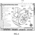
- FIG. 6 shows an example of the GUI of the system, wherein the system is a CAD system.
- the GUI of the example may be used to design the 3D modeled object and/or provide it at S10.
- the GUI 2100 may be a typical CAD-like interface, having standard menu bars 2110, 2120, as well as bottom and side toolbars 2140, 2150.
- Such menu- and toolbars contain a set of user-selectable icons, each icon being associated with one or more operations or functions, as known in the art.
- Some of these icons are associated with software tools, adapted for editing and/or working on the 3D modeled object 2000 displayed in the GUI 2100.
- the software tools may be grouped into workbenches. Each workbench comprises a subset of software tools. In particular, one of the workbenches is an edition workbench, suitable for editing geometrical features of the modeled product 2000.
- a designer may for example pre-select a part of the object 2000 and then initiate an operation (e.g. change the dimension, color, etc.) or edit geometrical constraints by selecting an appropriate icon.
- typical CAD operations are the modeling of the punching or the folding of the 3D modeled object displayed on the screen.
- the GUI may for example display data 2500 related to the displayed product 2000.
- the data 2500, displayed as a "feature tree", and their 3D representation 2000 pertain to a brake assembly including brake caliper and disc.
- the GUI may further show various types of graphic tools 2130, 2070, 2080 for example for facilitating 3D orientation of the object, for triggering a simulation of an operation of an edited product or render various attributes of the displayed product 2000.
- a cursor 2060 may be controlled by a haptic device to allow the user to interact with the graphic tools.
- FIG. 7 shows an example of the system, wherein the system is a client computer system, e.g. a workstation of a user.
- the system is a client computer system, e.g. a workstation of a user.
- the client computer of the example comprises a central processing unit (CPU) 1010 connected to an internal communication BUS 1000, a random access memory (RAM) 1070 also connected to the BUS.
- the client computer is further provided with a graphical processing unit (GPU) 1110 which is associated with a video random access memory 1100 connected to the BUS.
- Video RAM 1100 is also known in the art as frame buffer.
- a mass storage device controller 1020 manages accesses to a mass memory device, such as hard drive 1030.
- Mass memory devices suitable for tangibly embodying computer program instructions and data include all forms of nonvolatile memory, including by way of example semiconductor memory devices, such as EPROM, EEPROM, and flash memory devices; magnetic disks such as internal hard disks and removable disks; magneto-optical disks; and CD-ROM disks 1040. Any of the foregoing may be supplemented by, or incorporated in, specially designed ASICs (application-specific integrated circuits).
- a network adapter 1050 manages accesses to a network 1060.
- the client computer may also include a haptic device 1090 such as cursor control device, a keyboard or the like.
- a cursor control device is used in the client computer to permit the user to selectively position a cursor at any desired location on display 1080.
- the cursor control device allows the user to select various commands, and input control signals.
- the cursor control device includes a number of signal generation devices for input control signals to system.
- a cursor control device may be a mouse, the button of the mouse being used to generate the signals.
- the client computer system may comprise a sensitive pad, and/or a sensitive screen.
- the computer program may comprise instructions executable by a computer, the instructions comprising means for causing the above system to perform the method.
- the program may be recordable on any data storage medium, including the memory of the system.
- the program may for example be implemented in digital electronic circuitry, or in computer hardware, firmware, software, or in combinations of them.
- the program may be implemented as an apparatus, for example a product tangibly embodied in a machine-readable storage device for execution by a programmable processor. Method steps may be performed by a programmable processor executing a program of instructions to perform functions of the method by operating on input data and generating output.
- the processor may thus be programmable and coupled to receive data and instructions from, and to transmit data and instructions to, a data storage system, at least one input device, and at least one output device.
- the application program may be implemented in a high-level procedural or object-oriented programming language, or in assembly or machine language if desired. In any case, the language may be a compiled or interpreted language.
- the program may be a full installation program or an update program. Application of the program on the system results in any case in instructions for performing the method.
- the method may be included in a manufacturing process, which may comprise, after performing the method, producing a physical product corresponding to the mechanical part.
- the modeled object may represent a manufacturing object.
- the modeled object may thus be a modeled solid (i.e. a modeled object that represents a solid).
- the manufacturing object may be a product, such as a part, or an assembly of parts. Because the method improves the design of the modeled object, the method also improves the manufacturing of a product and thus increases productivity of the manufacturing process.
- the 3D modeled object may be provided at S10 as a B-Rep comprising edges.
- This format is widely used by designers to represent 3D shapes of mechanical parts.
- designers often design a B-Rep using edges in order to represent geometry that appears to correspond to instances of visual characteristics of reflection lines (except for ends of reflection lines corresponding to silhouette).
- the determining S20 may efficiently be performed among the edges of the B-Rep, at least partly (for example for all other continuous 3D curves than those corresponding to silhouette).
- topological entities are: face, edge, and vertex.
- Geometrical entities are 3D objects: surface, plane, curve, line, point.
- a face is a bounded portion of a surface, named the supporting surface.
- An edge is a bounded portion of a curve, named the supporting curve.
- a vertex is a point in 3D space. They are related to each other's as follows.
- the bounded portion of a curve is defined by two points (the vertices) lying on the curve.
- the bounded portion of a surface is defined by its boundary, this boundary being a set of edges lying on the surface. Edges of the face's boundary are connected together by sharing vertices. Faces are connected together by sharing edges.
- two faces are adjacent if they share an edge.
- two edges are adjacent if they share a vertex.
- FIGs. 8 and 9 illustrate the B-rep model of a cylindrical slot 80 that may be provided at S12 and that is made of three faces numbered 1, 2 and 3 on the figures: top planar face 1 and two lateral cylindrical faces 2 and 3.
- FIG. 8 shows a perspective view of slot 80.
- FIG. 9 shows the exploded view of all faces.
- Duplicated numbers illustrate edges and vertices sharing.
- Face 1 is a bounded portion of a plane. Boundary of face 1 includes edges 4 and 5, each of them being bounded by vertices 10 and 11. They both have the same supporting circle.
- Face 2 is bounded by edges 6, 8, 5 and 13 all lying on an infinite cylindrical surface (i.e. the supporting surface of face 2).
- Faces 1 and 2 are adjacent because they share edge 5.
- Faces 2 and 3 are adjacent because they share edges 8 and 13.
- Faces 1 and 3 are adjacent because they share edge 4.
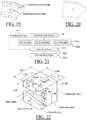
- FIG. 10 illustrates the "is bounded by" topological relationship of the B-rep model of slot 80. Nodes of higher layer 101 are faces, nodes of intermediate layer 103 are edges and nodes of lower layer 105 are vertices.
- FIGS. 11 and 12 illustrate the relationship between topological entities (faces, edges, vertices) and the supporting geometries (infinite cylinder, infinite plane, infinite line, points).
- the B-rep model gathers in an appropriate data structure the "is bounded by" relationship and the relationship between topological entities and supporting geometries, and mathematical descriptions of supporting geometries.
- the data structures shown on FIGS. 20 and 21 are part of the topological data of this example, which comprise links to geometrical entities of the geometrical data (this is FIG. 11 ) and links between topological entities (this is FIG. 10 ).
- the B-Rep model represents a closed skin if and only if all edges are shared by exactly two faces.
- a thick part may be represented by a solid, which is a closed skin.
- it represents an open skin if at least one edge is the boundary edge of only one face, meaning that it is not shared by another face. Such an edge is a named boundary edge.
- An edge shared by two faces is named an internal edge.
- a thin part like a sheet metal part, may be represented by an open skin, the thickness value being an associated numerical parameter.
- the determining S20 may be performed among the edges of the B-Rep in any way.
- the determining S20 may comprise applying one or more selection criteria, for example testing whether each of at least a part of the edges of the B-Rep meet the one or more selection criteria, and outputting edges for which the test is positive.
- the one or more selection criteria may relate to surface curvature at the tested edge.
- the one or more selection criteria may include a first category of one or more selection criteria.
- the first category may include being a curvature and tangent discontinuity curve (i.e. the B-Rep surface is curvature discontinuous and tangent discontinuous at the edge, e.g. because the edge is a boundary of the B-Rep which is an open surface or the edge corresponds to a sharp crease of the B-Rep) and optionally being a curvature discontinuity and tangent continuity curve (i.e. the B-Rep surface is tangent continuous but curvature discontinuous at the edge), for example being an at least curvature discontinuity curve.
- the first category may be implemented in any way.
- the B-Rep format provided at S10 already comprises for edges meeting the first category information indicative of that, such as information indicative that the edge is a "sharp” edge e.g. via a "sharp edge” flag or a "boundary edge”.
- the first category allows detecting B-Rep edges corresponding to surface geometrical singularities. Such geometrical singularities are visually observable, such that representing them in the final 2D drawing is relevant.
- the 3D modeled object represents the geometry of a product to be manufactured in the real world subsequent to the completion of its virtual design with for instance a CAD software solution or CAD system, that is a mechanical part (which encompasses assemblies of parts, as an assembly of parts may be seen as a mechanical part itself, or the method may be applied independently to each part of the assembly, or more generally any rigid body assembly e.g. a mobile mechanism).
- a CAD software solution allows the design of products in various and unlimited industrial fields, including: aerospace, architecture, construction, consumer goods, high-tech devices, industrial equipment, transportation, marine, and/or offshore oil/gas production or transportation.
- the 3D modeled object of the method may thus represent an industrial product which may be any mechanical part, such as a part of a terrestrial vehicle (including e.g. car and light truck equipment, racing cars, motorcycles, truck and motor equipment, trucks and buses, trains), a part of an aerial vehicle (including e.g. airframe equipment, aerospace equipment, propulsion equipment, defense products, airline equipment, space equipment), a part of a naval vehicle (including e.g. navy equipment, commercial ships, offshore equipment, yachts and workboats, marine equipment), a general mechanical part (including e.g. industrial manufacturing machinery, heavy mobile machinery or equipment, installed equipment, industrial equipment product, fabricated metal product, tire manufacturing product), an electro-mechanical or electronic part (including e.g.
- a terrestrial vehicle including e.g. car and light truck equipment, racing cars, motorcycles, truck and motor equipment, trucks and buses, trains
- an aerial vehicle including e.g. airframe equipment, aerospace equipment, propulsion equipment, defense products, airline equipment, space equipment
- a consumer good including e.g. furniture, home and garden products, leisure goods, fashion products, hard goods retailers' products, soft goods retailers' products
- a packaging including e.g. food and beverage and tobacco, beauty and personal care, household product packaging.
- the mechanical part may be such that the B-Rep features relatively many sharp edges.
- the mechanical part may for example be a part obtained through a turning, grooving, drilling and/or milling manufacturing process.
- the determining S20 may consist in computing the silhouette and selecting all sharp edges (e.g. including if any boundary edges) and no other edges of the B-Rep.
- FIG. 2 represents an example of such a part and shows that the result in such a case allows understanding the 3D shape of the part. This is because functional details such as hole, groove, pocket, are localized by sharp edges e.g. resulting from material removal.
- the determining S20 may consist in computing the silhouette and selecting all edges of the B-Rep.
- the generated 2D drawing remains non-superfluous in 2D lines, because the B-Rep of the contemplated mechanical part may comprise few smooth edges that are going to be superfluous after projection S30 (i.e. smooth edges being B-Rep surface curvature continuity edges, and optionally tangent continuity edges).
- the mechanical part may however alternatively be a sheet metal part, and/or corresponding to a manufacturing process which is a stamping and/or casting process.
- the situation with stamping sheet metal parts may be different from the one of FIG. 2 . They may not naturally feature sharp edges neighboring functional details e.g. because they are obtained by material deformation as opposed to material removal.
- FIGs. 13-18 illustrate this aspect.
- FIGs. 13-14 notably illustrate typical sheet metal parts.
- FIGs. 15-17 illustrate typical metal stamping parts for automotive industry.
- FIG. 18 figure illustrates a typical body in white assembly of parts.
- FIG. 19 illustrates projection of all edges of a sheet metal part. The 3D shape is understandable, but many smooth edges are superfluous.
- FIG. 20 illustrates the same part with boundary edges and silhouette curves only, making the variable radius surface imperceptible. Clearly, drawing only silhouette curves and sharp edges (including boundary edges if any) of a stamping sheet metal part does not help to understand its actual shape.
- the method may thus in an example determine at S20 smooth edges and only those smooth edges that help understanding the shape of the part. Displaying these edges, together with silhouette curves and sharp edges (including boundary edges if any), provides a drawing that does not require any further cleaning and that makes the shape of the part understandable. As a result, no hand cleaning is needed when the drawing is computed by using the method. Saved time is productivity improvement. Additional calculation performed by the method does not increase the overall time for the CAD system to provide the whole drawing. This makes the implementation transparent from the computing time point of view. In addition, computing a correct drawing at first shot allows associativity. This means that modifying the input part and updating yields a new version of the same drawing. This way, downstream applications reusing the drawing can be updated in turn through an automatic process.
- FIG. 21 shows a flowchart of such an example of the method. The determining S20 of the example may be performed solely based on surface curvature consideration.
- the continuous 3D curves determined at S20 and projected at S30 are the following and only the following curves:
- the determining S20 may comprise determining smooth edges which define the boundary between two adjacent faces across which the variation of a curvature is above a predetermined threshold. This allows grasping visible smooth edges, as will be described later.
- the curvature of a respective face relative to such a respective boundary smooth edge may be a function of the curvature at one or more points of a curve of the respective face intersecting the respective boundary smooth edge.
- the curve of the respective face intersecting the respective boundary may intersect the respective boundary smooth edge orthogonally and/or at a middle point of the respective boundary smooth edge.
- the one or points of the curve of the respective face intersecting the respective boundary smooth edge (and of which the curvature of a respective face relative to such a respective boundary smooth edge is a function) may include a point at which the curve of the respective face intersecting the respective boundary intersects the respective boundary smooth edge and/or a middle point of the curve. This provides an accurate result.
- faces of the B-Rep may be processed as portions of parametric surfaces, and curves thereon may be processed as p-curves (in terms of processed data structures). This allows efficiency in the computation.
- a smooth edge is in the example implementation an internal edge with two tangent adjacent faces.
- a sharp edge is a boundary edge or an internal edge with two non-tangent adjacent faces.
- a silhouette point is where the sign of the scalar product between the view direction D and the B-Rep normal vector changes.
- the formal definition is as follows. Note N ( P ) the normal vector of the B-Rep at point P .
- a point X of the B-Rep is a silhouette point if for arbitrary small ⁇ > 0 there exist two points Y and Z of the B-Rep such that ⁇ X - Y ⁇ ⁇ ⁇ , ⁇ X - Z ⁇ ⁇ ⁇ , ⁇ N ( Y ) ,D ⁇ > 0 and ⁇ N ( Z ) ,D ⁇ ⁇ 0.
- This definition includes silhouette points located on sharp edges, where the normal vector is not defined.
- the silhouette curve is the curve made of all silhouette points. FiGs. 22-23 illustrate each situation.
- the reflection line is one time less smooth than the surface. This means that where the matching is continuous but not tangent continuous, the reflection line is not continuous ( FIG. 24 ), where the matching is tangent continuous but not curvature continuous ( FIG. 25 ), the reflection line is not tangent continuous (it features a sharp point) and where the matching is curvature continuous ( FIG. 26 ), the reflection line is tangent continuous.
- the determining S20 may determine directly the silhouette and all sharp edges, thereby grasping reflection lines' visual characteristics represented on FIG. 24 and FIG. 25 and allowing their projection at S30. Now, smooth edges (corresponding to FIG. 26 ) may sometimes be relevant to also project at S30. This is when they are said to be "visible”. The determining S20 may detect such visibility as follows.
- the example implementation may make use of curvature values of 3D curves.
- curvature k ( t ) is defined by the second derivative with respect to arc length, as described for example at page 16 of the paper by M.P. do Carmo, Differential Geometry of curves and surfaces, Prentice-Hall, 1976. Nevertheless, it can be evaluated without explicit arc length by using the following formula, where C' ( t ) and C" ( t ) are respectively the first and second derivatives of C ( ⁇ ).
- a parametric surface is a mapping S : a b ⁇ c d ⁇ R 3 with notation ( u,v ) ⁇ S ( u,v ).
- the tangent plane of surface S at point ( u,v ) ⁇ [ a , b] ⁇ [ c,d ] is the plane through point S u v ⁇ R 3 generated by partial derivative vectors S u u v ⁇ R 3 and S v u v ⁇ R 3 .
- a p-curve of surface S is a mapping ( ⁇ , ⁇ ): [ a',b' ] ⁇ [ a,b ] ⁇ [ c,d ] in the parametric space of S . Notation is t ⁇ ( ⁇ ( t ), ⁇ ( t )). This p-curve defines a 3D curve through the chaining t ⁇ S ( ⁇ ( t ) , ⁇ ( t )).
- the example implementation computes the direction of a p-curve based on a 3D vector in the tangent plane of the surface.
- p-curve computation is an efficient way to computer curve on a surface.
- E be a smooth edge of the skin model representing the mechanical part
- F 1 , F 2 the adjacent faces of E
- M 0 the middle point of E and P the tangent plane shared by faces F 1 and F 2 at M 0 .
- T 0 the tangent vector to E at M 0 .
- T i 1,2
- T i the direction in plane P perpendicular to T 0 pointing in the direction of F i .
- C i the curve in face F i starting at M 0 in direction T i .
- Curves C i are obtained by using the formula of previous paragraph with support surfaces of faces F i .
- the smooth edge E is selected for visualization if k 2 max ⁇ k 1 max ⁇ 1 R
- the predetermined threshold 1 R may in general correspond to the maximum radius R used in a process of manufacturing the mechanical part.
- R may be a value above 10mm and/or below 50mm, for example of the order of 30mm.
- R may be a value above 1mm and/or below 10mm, for example of the order of 3mm. This allows grasping relevant edges by integrating relevant knowledge of the manufacturing process.
- FIG. 32 illustrates all edges of a sheet metal part.
- FIG. 33 illustrates all boundary edges and silhouette edges.
- FIG. 34 illustrates all boundary and silhouette edges together with smooth edges selected by the method. Notice that superfluous edges are removed while the 3D shape remains understandable.
Priority Applications (4)
| Application Number | Priority Date | Filing Date | Title |
|---|---|---|---|
| EP17306268.8A EP3460760B1 (en) | 2017-09-26 | 2017-09-26 | Generating a 2d drawing representing a mechanical part |
| JP2018177551A JP7235462B2 (ja) | 2017-09-26 | 2018-09-21 | 機械部品を表す2d図面の生成 |
| CN201811124191.7A CN109558624B (zh) | 2017-09-26 | 2018-09-26 | 生成代表机械部件的2d绘图 |
| US16/143,063 US10650572B2 (en) | 2017-09-26 | 2018-09-26 | Generating a 2D drawing representing a mechanical part |
Applications Claiming Priority (1)
| Application Number | Priority Date | Filing Date | Title |
|---|---|---|---|
| EP17306268.8A EP3460760B1 (en) | 2017-09-26 | 2017-09-26 | Generating a 2d drawing representing a mechanical part |
Publications (2)
| Publication Number | Publication Date |
|---|---|
| EP3460760A1 EP3460760A1 (en) | 2019-03-27 |
| EP3460760B1 true EP3460760B1 (en) | 2021-05-19 |
Family
ID=60019844
Family Applications (1)
| Application Number | Title | Priority Date | Filing Date |
|---|---|---|---|
| EP17306268.8A Active EP3460760B1 (en) | 2017-09-26 | 2017-09-26 | Generating a 2d drawing representing a mechanical part |
Country Status (4)
| Country | Link |
|---|---|
| US (1) | US10650572B2 (ja) |
| EP (1) | EP3460760B1 (ja) |
| JP (1) | JP7235462B2 (ja) |
| CN (1) | CN109558624B (ja) |
Families Citing this family (7)
| Publication number | Priority date | Publication date | Assignee | Title |
|---|---|---|---|---|
| EP3554349A4 (en) | 2016-12-19 | 2020-06-17 | Lantos Technologies, Inc. | MANUFACTURE OF INFLATABLE MEMBRANES |
| US11030361B2 (en) * | 2018-10-31 | 2021-06-08 | Detroit Engineered Products, Inc. | Automated modelling system |
| EP3671660A1 (en) * | 2018-12-20 | 2020-06-24 | Dassault Systèmes | Designing a 3d modeled object via user-interaction |
| EP3690682A1 (en) | 2019-02-01 | 2020-08-05 | Dassault Systèmes | Designing a part featuring a protrusion or a depression |
| EP3761211A1 (en) * | 2019-07-04 | 2021-01-06 | Dassault Systèmes | Designing a part featuring a bump |
| CN111813049B (zh) * | 2020-07-31 | 2021-10-08 | 东莞市中泰模具股份有限公司 | 翻孔凹模及其制造方法、存储介质和cnc机床 |
| CN112347288B (zh) * | 2020-11-10 | 2024-02-20 | 北京北大方正电子有限公司 | 一种字图的矢量化方法 |
Family Cites Families (11)
| Publication number | Priority date | Publication date | Assignee | Title |
|---|---|---|---|---|
| US5297241A (en) * | 1991-09-30 | 1994-03-22 | Hewlett-Packard Company | Automated re-layout with dimensional associativity |
| US6717579B1 (en) | 1999-06-10 | 2004-04-06 | Dassault Systemes | Reflection line control |
| CN1391683A (zh) * | 1999-07-23 | 2003-01-15 | 鲍尔塔克奥夫公司 | 使用控制几何的几何设计和建模系统 |
| US7813901B2 (en) * | 2004-10-25 | 2010-10-12 | Amada Company, Limited | Sketch generator for 3D sheet metal part models created by sheet metal part feature operations |
| WO2006073036A1 (ja) | 2005-01-07 | 2006-07-13 | National University Corporation Yokohama National University | 形状評価方法、形状評価装置、及び形状評価装置を備えた装置 |
| EP2383669B1 (en) * | 2010-04-02 | 2018-07-11 | Dassault Systèmes | Design of a part modeled by parallel geodesic curves |
| JP5004109B2 (ja) * | 2010-05-27 | 2012-08-22 | トヨタ自動車株式会社 | 3次元形状データの作成方法、3次元形状データの作成装置および3次元形状データの作成プログラム |
| US8711143B2 (en) * | 2010-08-25 | 2014-04-29 | Adobe Systems Incorporated | System and method for interactive image-based modeling of curved surfaces using single-view and multi-view feature curves |
| EP2600315B1 (en) * | 2011-11-29 | 2019-04-10 | Dassault Systèmes | Creating a surface from a plurality of 3D curves |
| EP2750107B1 (en) * | 2012-12-31 | 2017-03-15 | Dassault Systèmes | Groups of faces that form a geometrical pattern |
| WO2015077113A1 (en) * | 2013-11-25 | 2015-05-28 | Corning Incorporated | Methods for determining a shape of a substantially cylindrical specular reflective surface |
-
2017
- 2017-09-26 EP EP17306268.8A patent/EP3460760B1/en active Active
-
2018
- 2018-09-21 JP JP2018177551A patent/JP7235462B2/ja active Active
- 2018-09-26 CN CN201811124191.7A patent/CN109558624B/zh active Active
- 2018-09-26 US US16/143,063 patent/US10650572B2/en active Active
Non-Patent Citations (1)
| Title |
|---|
| None * |
Also Published As
| Publication number | Publication date |
|---|---|
| EP3460760A1 (en) | 2019-03-27 |
| CN109558624B (zh) | 2023-11-07 |
| JP2019075103A (ja) | 2019-05-16 |
| US20190096120A1 (en) | 2019-03-28 |
| CN109558624A (zh) | 2019-04-02 |
| JP7235462B2 (ja) | 2023-03-08 |
| US10650572B2 (en) | 2020-05-12 |
Similar Documents
| Publication | Publication Date | Title |
|---|---|---|
| EP3460760B1 (en) | Generating a 2d drawing representing a mechanical part | |
| US11027493B2 (en) | Additive manufacturing of a 3D part | |
| US9330498B2 (en) | Path connecting a first point to a second point in a three-dimensional scene | |
| US8750598B2 (en) | Watermarking of a 3D modeled object | |
| CN105760570B (zh) | 选择对象集的视点 | |
| KR20160082481A (ko) | 워크피스의 가공의 시뮬레이팅 | |
| US20150294036A1 (en) | Fitting sample points with an isovalue surface | |
| US20170160726A1 (en) | Detecting cut-outs | |
| US8823706B2 (en) | Method, program and product edition system for visualizing objects displayed on a computer screen | |
| US20150294502A1 (en) | Sample points of 3d curves sketched by a user | |
| EP2921978B1 (en) | Designing industrial products by using geometries connected by geometrical constraints | |
| US11886777B2 (en) | 3D design of B-rep skin | |
| US20230177229A1 (en) | Partitioning 3d cad model | |
| US20230114354A1 (en) | Designing a modeled object | |
| US11941325B2 (en) | 3D modeled object of a physical prototype of a product | |
| US20210240887A1 (en) | Structural simulation of a mechanical part |
Legal Events
| Date | Code | Title | Description |
|---|---|---|---|
| PUAI | Public reference made under article 153(3) epc to a published international application that has entered the european phase |
Free format text: ORIGINAL CODE: 0009012 |
|
| STAA | Information on the status of an ep patent application or granted ep patent |
Free format text: STATUS: THE APPLICATION HAS BEEN PUBLISHED |
|
| AK | Designated contracting states |
Kind code of ref document: A1 Designated state(s): AL AT BE BG CH CY CZ DE DK EE ES FI FR GB GR HR HU IE IS IT LI LT LU LV MC MK MT NL NO PL PT RO RS SE SI SK SM TR |
|
| AX | Request for extension of the european patent |
Extension state: BA ME |
|
| STAA | Information on the status of an ep patent application or granted ep patent |
Free format text: STATUS: REQUEST FOR EXAMINATION WAS MADE |
|
| 17P | Request for examination filed |
Effective date: 20190927 |
|
| RBV | Designated contracting states (corrected) |
Designated state(s): AL AT BE BG CH CY CZ DE DK EE ES FI FR GB GR HR HU IE IS IT LI LT LU LV MC MK MT NL NO PL PT RO RS SE SI SK SM TR |
|
| RIC1 | Information provided on ipc code assigned before grant |
Ipc: G06T 15/20 20110101AFI20200720BHEP Ipc: G06T 17/30 20060101ALI20200720BHEP Ipc: G06T 17/10 20060101ALI20200720BHEP |
|
| GRAP | Despatch of communication of intention to grant a patent |
Free format text: ORIGINAL CODE: EPIDOSNIGR1 |
|
| STAA | Information on the status of an ep patent application or granted ep patent |
Free format text: STATUS: GRANT OF PATENT IS INTENDED |
|
| INTG | Intention to grant announced |
Effective date: 20201215 |
|
| RIN1 | Information on inventor provided before grant (corrected) |
Inventor name: RORATO, REMY |
|
| GRAS | Grant fee paid |
Free format text: ORIGINAL CODE: EPIDOSNIGR3 |
|
| GRAA | (expected) grant |
Free format text: ORIGINAL CODE: 0009210 |
|
| STAA | Information on the status of an ep patent application or granted ep patent |
Free format text: STATUS: THE PATENT HAS BEEN GRANTED |
|
| AK | Designated contracting states |
Kind code of ref document: B1 Designated state(s): AL AT BE BG CH CY CZ DE DK EE ES FI FR GB GR HR HU IE IS IT LI LT LU LV MC MK MT NL NO PL PT RO RS SE SI SK SM TR |
|
| REG | Reference to a national code |
Ref country code: GB Ref legal event code: FG4D |
|
| REG | Reference to a national code |
Ref country code: CH Ref legal event code: EP |
|
| REG | Reference to a national code |
Ref country code: DE Ref legal event code: R096 Ref document number: 602017038771 Country of ref document: DE |
|
| REG | Reference to a national code |
Ref country code: AT Ref legal event code: REF Ref document number: 1394714 Country of ref document: AT Kind code of ref document: T Effective date: 20210615 |
|
| REG | Reference to a national code |
Ref country code: IE Ref legal event code: FG4D |
|
| REG | Reference to a national code |
Ref country code: SE Ref legal event code: TRGR |
|
| REG | Reference to a national code |
Ref country code: LT Ref legal event code: MG9D |
|
| REG | Reference to a national code |
Ref country code: AT Ref legal event code: MK05 Ref document number: 1394714 Country of ref document: AT Kind code of ref document: T Effective date: 20210519 |
|
| REG | Reference to a national code |
Ref country code: NL Ref legal event code: MP Effective date: 20210519 |
|
| PG25 | Lapsed in a contracting state [announced via postgrant information from national office to epo] |
Ref country code: HR Free format text: LAPSE BECAUSE OF FAILURE TO SUBMIT A TRANSLATION OF THE DESCRIPTION OR TO PAY THE FEE WITHIN THE PRESCRIBED TIME-LIMIT Effective date: 20210519 Ref country code: AT Free format text: LAPSE BECAUSE OF FAILURE TO SUBMIT A TRANSLATION OF THE DESCRIPTION OR TO PAY THE FEE WITHIN THE PRESCRIBED TIME-LIMIT Effective date: 20210519 Ref country code: BG Free format text: LAPSE BECAUSE OF FAILURE TO SUBMIT A TRANSLATION OF THE DESCRIPTION OR TO PAY THE FEE WITHIN THE PRESCRIBED TIME-LIMIT Effective date: 20210819 Ref country code: FI Free format text: LAPSE BECAUSE OF FAILURE TO SUBMIT A TRANSLATION OF THE DESCRIPTION OR TO PAY THE FEE WITHIN THE PRESCRIBED TIME-LIMIT Effective date: 20210519 Ref country code: LT Free format text: LAPSE BECAUSE OF FAILURE TO SUBMIT A TRANSLATION OF THE DESCRIPTION OR TO PAY THE FEE WITHIN THE PRESCRIBED TIME-LIMIT Effective date: 20210519 |
|
| PG25 | Lapsed in a contracting state [announced via postgrant information from national office to epo] |
Ref country code: IS Free format text: LAPSE BECAUSE OF FAILURE TO SUBMIT A TRANSLATION OF THE DESCRIPTION OR TO PAY THE FEE WITHIN THE PRESCRIBED TIME-LIMIT Effective date: 20210919 Ref country code: LV Free format text: LAPSE BECAUSE OF FAILURE TO SUBMIT A TRANSLATION OF THE DESCRIPTION OR TO PAY THE FEE WITHIN THE PRESCRIBED TIME-LIMIT Effective date: 20210519 Ref country code: GR Free format text: LAPSE BECAUSE OF FAILURE TO SUBMIT A TRANSLATION OF THE DESCRIPTION OR TO PAY THE FEE WITHIN THE PRESCRIBED TIME-LIMIT Effective date: 20210820 Ref country code: PL Free format text: LAPSE BECAUSE OF FAILURE TO SUBMIT A TRANSLATION OF THE DESCRIPTION OR TO PAY THE FEE WITHIN THE PRESCRIBED TIME-LIMIT Effective date: 20210519 Ref country code: PT Free format text: LAPSE BECAUSE OF FAILURE TO SUBMIT A TRANSLATION OF THE DESCRIPTION OR TO PAY THE FEE WITHIN THE PRESCRIBED TIME-LIMIT Effective date: 20210920 Ref country code: NO Free format text: LAPSE BECAUSE OF FAILURE TO SUBMIT A TRANSLATION OF THE DESCRIPTION OR TO PAY THE FEE WITHIN THE PRESCRIBED TIME-LIMIT Effective date: 20210819 Ref country code: RS Free format text: LAPSE BECAUSE OF FAILURE TO SUBMIT A TRANSLATION OF THE DESCRIPTION OR TO PAY THE FEE WITHIN THE PRESCRIBED TIME-LIMIT Effective date: 20210519 |
|
| PG25 | Lapsed in a contracting state [announced via postgrant information from national office to epo] |
Ref country code: NL Free format text: LAPSE BECAUSE OF FAILURE TO SUBMIT A TRANSLATION OF THE DESCRIPTION OR TO PAY THE FEE WITHIN THE PRESCRIBED TIME-LIMIT Effective date: 20210519 |
|
| PG25 | Lapsed in a contracting state [announced via postgrant information from national office to epo] |
Ref country code: SK Free format text: LAPSE BECAUSE OF FAILURE TO SUBMIT A TRANSLATION OF THE DESCRIPTION OR TO PAY THE FEE WITHIN THE PRESCRIBED TIME-LIMIT Effective date: 20210519 Ref country code: SM Free format text: LAPSE BECAUSE OF FAILURE TO SUBMIT A TRANSLATION OF THE DESCRIPTION OR TO PAY THE FEE WITHIN THE PRESCRIBED TIME-LIMIT Effective date: 20210519 Ref country code: CZ Free format text: LAPSE BECAUSE OF FAILURE TO SUBMIT A TRANSLATION OF THE DESCRIPTION OR TO PAY THE FEE WITHIN THE PRESCRIBED TIME-LIMIT Effective date: 20210519 Ref country code: DK Free format text: LAPSE BECAUSE OF FAILURE TO SUBMIT A TRANSLATION OF THE DESCRIPTION OR TO PAY THE FEE WITHIN THE PRESCRIBED TIME-LIMIT Effective date: 20210519 Ref country code: EE Free format text: LAPSE BECAUSE OF FAILURE TO SUBMIT A TRANSLATION OF THE DESCRIPTION OR TO PAY THE FEE WITHIN THE PRESCRIBED TIME-LIMIT Effective date: 20210519 Ref country code: ES Free format text: LAPSE BECAUSE OF FAILURE TO SUBMIT A TRANSLATION OF THE DESCRIPTION OR TO PAY THE FEE WITHIN THE PRESCRIBED TIME-LIMIT Effective date: 20210519 Ref country code: RO Free format text: LAPSE BECAUSE OF FAILURE TO SUBMIT A TRANSLATION OF THE DESCRIPTION OR TO PAY THE FEE WITHIN THE PRESCRIBED TIME-LIMIT Effective date: 20210519 |
|
| REG | Reference to a national code |
Ref country code: DE Ref legal event code: R097 Ref document number: 602017038771 Country of ref document: DE |
|
| PLBE | No opposition filed within time limit |
Free format text: ORIGINAL CODE: 0009261 |
|
| STAA | Information on the status of an ep patent application or granted ep patent |
Free format text: STATUS: NO OPPOSITION FILED WITHIN TIME LIMIT |
|
| 26N | No opposition filed |
Effective date: 20220222 |
|
| REG | Reference to a national code |
Ref country code: CH Ref legal event code: PL |
|
| REG | Reference to a national code |
Ref country code: BE Ref legal event code: MM Effective date: 20210930 |
|
| PG25 | Lapsed in a contracting state [announced via postgrant information from national office to epo] |
Ref country code: IS Free format text: LAPSE BECAUSE OF FAILURE TO SUBMIT A TRANSLATION OF THE DESCRIPTION OR TO PAY THE FEE WITHIN THE PRESCRIBED TIME-LIMIT Effective date: 20210919 Ref country code: MC Free format text: LAPSE BECAUSE OF FAILURE TO SUBMIT A TRANSLATION OF THE DESCRIPTION OR TO PAY THE FEE WITHIN THE PRESCRIBED TIME-LIMIT Effective date: 20210519 Ref country code: AL Free format text: LAPSE BECAUSE OF FAILURE TO SUBMIT A TRANSLATION OF THE DESCRIPTION OR TO PAY THE FEE WITHIN THE PRESCRIBED TIME-LIMIT Effective date: 20210519 |
|
| PG25 | Lapsed in a contracting state [announced via postgrant information from national office to epo] |
Ref country code: LU Free format text: LAPSE BECAUSE OF NON-PAYMENT OF DUE FEES Effective date: 20210926 Ref country code: IE Free format text: LAPSE BECAUSE OF NON-PAYMENT OF DUE FEES Effective date: 20210926 Ref country code: BE Free format text: LAPSE BECAUSE OF NON-PAYMENT OF DUE FEES Effective date: 20210930 |
|
| PG25 | Lapsed in a contracting state [announced via postgrant information from national office to epo] |
Ref country code: LI Free format text: LAPSE BECAUSE OF NON-PAYMENT OF DUE FEES Effective date: 20210930 Ref country code: CH Free format text: LAPSE BECAUSE OF NON-PAYMENT OF DUE FEES Effective date: 20210930 |
|
| PG25 | Lapsed in a contracting state [announced via postgrant information from national office to epo] |
Ref country code: CY Free format text: LAPSE BECAUSE OF FAILURE TO SUBMIT A TRANSLATION OF THE DESCRIPTION OR TO PAY THE FEE WITHIN THE PRESCRIBED TIME-LIMIT Effective date: 20210519 |
|
| P01 | Opt-out of the competence of the unified patent court (upc) registered |
Effective date: 20230527 |
|
| PG25 | Lapsed in a contracting state [announced via postgrant information from national office to epo] |
Ref country code: HU Free format text: LAPSE BECAUSE OF FAILURE TO SUBMIT A TRANSLATION OF THE DESCRIPTION OR TO PAY THE FEE WITHIN THE PRESCRIBED TIME-LIMIT; INVALID AB INITIO Effective date: 20170926 |
|
| PGFP | Annual fee paid to national office [announced via postgrant information from national office to epo] |
Ref country code: GB Payment date: 20230920 Year of fee payment: 7 |
|
| PGFP | Annual fee paid to national office [announced via postgrant information from national office to epo] |
Ref country code: SE Payment date: 20230920 Year of fee payment: 7 Ref country code: FR Payment date: 20230928 Year of fee payment: 7 Ref country code: DE Payment date: 20230920 Year of fee payment: 7 |
|
| PGFP | Annual fee paid to national office [announced via postgrant information from national office to epo] |
Ref country code: IT Payment date: 20230927 Year of fee payment: 7 |
|
| PG25 | Lapsed in a contracting state [announced via postgrant information from national office to epo] |
Ref country code: MK Free format text: LAPSE BECAUSE OF FAILURE TO SUBMIT A TRANSLATION OF THE DESCRIPTION OR TO PAY THE FEE WITHIN THE PRESCRIBED TIME-LIMIT Effective date: 20210519 |