EP3460397B1 - Ansteuerungsschaltung und verfahren für ein mems-gyroskop und zugehöriges mems-gyroskop - Google Patents
Ansteuerungsschaltung und verfahren für ein mems-gyroskop und zugehöriges mems-gyroskop Download PDFInfo
- Publication number
- EP3460397B1 EP3460397B1 EP18188832.2A EP18188832A EP3460397B1 EP 3460397 B1 EP3460397 B1 EP 3460397B1 EP 18188832 A EP18188832 A EP 18188832A EP 3460397 B1 EP3460397 B1 EP 3460397B1
- Authority
- EP
- European Patent Office
- Prior art keywords
- amplitude
- drive
- oscillation
- signal
- mems gyroscope
- Prior art date
- Legal status (The legal status is an assumption and is not a legal conclusion. Google has not performed a legal analysis and makes no representation as to the accuracy of the status listed.)
- Active
Links
- 238000000034 method Methods 0.000 title claims description 14
- 230000010355 oscillation Effects 0.000 claims description 67
- 238000001514 detection method Methods 0.000 claims description 28
- 238000005259 measurement Methods 0.000 claims description 24
- 230000000694 effects Effects 0.000 claims description 9
- NCGICGYLBXGBGN-UHFFFAOYSA-N 3-morpholin-4-yl-1-oxa-3-azonia-2-azanidacyclopent-3-en-5-imine;hydrochloride Chemical compound Cl.[N-]1OC(=N)C=[N+]1N1CCOCC1 NCGICGYLBXGBGN-UHFFFAOYSA-N 0.000 claims description 8
- 230000014509 gene expression Effects 0.000 claims description 6
- 238000013461 design Methods 0.000 description 6
- 238000006073 displacement reaction Methods 0.000 description 5
- 230000035945 sensitivity Effects 0.000 description 5
- 230000008901 benefit Effects 0.000 description 4
- 238000010586 diagram Methods 0.000 description 4
- 239000000758 substrate Substances 0.000 description 4
- 238000005516 engineering process Methods 0.000 description 3
- 238000012545 processing Methods 0.000 description 3
- 230000001105 regulatory effect Effects 0.000 description 3
- 230000008878 coupling Effects 0.000 description 2
- 238000010168 coupling process Methods 0.000 description 2
- 238000005859 coupling reaction Methods 0.000 description 2
- 230000001419 dependent effect Effects 0.000 description 2
- 230000005284 excitation Effects 0.000 description 2
- 238000004519 manufacturing process Methods 0.000 description 2
- 239000000463 material Substances 0.000 description 2
- 230000008569 process Effects 0.000 description 2
- 238000013139 quantization Methods 0.000 description 2
- 239000004065 semiconductor Substances 0.000 description 2
- 238000004088 simulation Methods 0.000 description 2
- 230000005483 Hooke's law Effects 0.000 description 1
- 230000001133 acceleration Effects 0.000 description 1
- 230000009471 action Effects 0.000 description 1
- 230000032683 aging Effects 0.000 description 1
- 230000003679 aging effect Effects 0.000 description 1
- 230000003321 amplification Effects 0.000 description 1
- 238000004458 analytical method Methods 0.000 description 1
- 238000013459 approach Methods 0.000 description 1
- 238000003486 chemical etching Methods 0.000 description 1
- 238000006243 chemical reaction Methods 0.000 description 1
- 238000011217 control strategy Methods 0.000 description 1
- 230000001276 controlling effect Effects 0.000 description 1
- 238000013016 damping Methods 0.000 description 1
- 230000007613 environmental effect Effects 0.000 description 1
- 238000011156 evaluation Methods 0.000 description 1
- 238000001914 filtration Methods 0.000 description 1
- 230000036039 immunity Effects 0.000 description 1
- 230000010354 integration Effects 0.000 description 1
- 238000005459 micromachining Methods 0.000 description 1
- 238000012986 modification Methods 0.000 description 1
- 230000004048 modification Effects 0.000 description 1
- 238000003199 nucleic acid amplification method Methods 0.000 description 1
- 229910021420 polycrystalline silicon Inorganic materials 0.000 description 1
- 230000004044 response Effects 0.000 description 1
- 230000003068 static effect Effects 0.000 description 1
Images


Classifications
-
- G—PHYSICS
- G01—MEASURING; TESTING
- G01C—MEASURING DISTANCES, LEVELS OR BEARINGS; SURVEYING; NAVIGATION; GYROSCOPIC INSTRUMENTS; PHOTOGRAMMETRY OR VIDEOGRAMMETRY
- G01C19/00—Gyroscopes; Turn-sensitive devices using vibrating masses; Turn-sensitive devices without moving masses; Measuring angular rate using gyroscopic effects
- G01C19/56—Turn-sensitive devices using vibrating masses, e.g. vibratory angular rate sensors based on Coriolis forces
- G01C19/5642—Turn-sensitive devices using vibrating masses, e.g. vibratory angular rate sensors based on Coriolis forces using vibrating bars or beams
- G01C19/5649—Signal processing
-
- G—PHYSICS
- G01—MEASURING; TESTING
- G01C—MEASURING DISTANCES, LEVELS OR BEARINGS; SURVEYING; NAVIGATION; GYROSCOPIC INSTRUMENTS; PHOTOGRAMMETRY OR VIDEOGRAMMETRY
- G01C19/00—Gyroscopes; Turn-sensitive devices using vibrating masses; Turn-sensitive devices without moving masses; Measuring angular rate using gyroscopic effects
- G01C19/56—Turn-sensitive devices using vibrating masses, e.g. vibratory angular rate sensors based on Coriolis forces
- G01C19/5776—Signal processing not specific to any of the devices covered by groups G01C19/5607 - G01C19/5719
-
- G—PHYSICS
- G01—MEASURING; TESTING
- G01C—MEASURING DISTANCES, LEVELS OR BEARINGS; SURVEYING; NAVIGATION; GYROSCOPIC INSTRUMENTS; PHOTOGRAMMETRY OR VIDEOGRAMMETRY
- G01C19/00—Gyroscopes; Turn-sensitive devices using vibrating masses; Turn-sensitive devices without moving masses; Measuring angular rate using gyroscopic effects
- G01C19/56—Turn-sensitive devices using vibrating masses, e.g. vibratory angular rate sensors based on Coriolis forces
- G01C19/5642—Turn-sensitive devices using vibrating masses, e.g. vibratory angular rate sensors based on Coriolis forces using vibrating bars or beams
- G01C19/5656—Turn-sensitive devices using vibrating masses, e.g. vibratory angular rate sensors based on Coriolis forces using vibrating bars or beams the devices involving a micromechanical structure
-
- G—PHYSICS
- G01—MEASURING; TESTING
- G01C—MEASURING DISTANCES, LEVELS OR BEARINGS; SURVEYING; NAVIGATION; GYROSCOPIC INSTRUMENTS; PHOTOGRAMMETRY OR VIDEOGRAMMETRY
- G01C19/00—Gyroscopes; Turn-sensitive devices using vibrating masses; Turn-sensitive devices without moving masses; Measuring angular rate using gyroscopic effects
- G01C19/56—Turn-sensitive devices using vibrating masses, e.g. vibratory angular rate sensors based on Coriolis forces
- G01C19/5705—Turn-sensitive devices using vibrating masses, e.g. vibratory angular rate sensors based on Coriolis forces using masses driven in reciprocating rotary motion about an axis
- G01C19/5712—Turn-sensitive devices using vibrating masses, e.g. vibratory angular rate sensors based on Coriolis forces using masses driven in reciprocating rotary motion about an axis the devices involving a micromechanical structure
Definitions
- the present invention relates to a driving circuit and a driving method for a MEMS gyroscope, in particular a MEMS gyroscope operating on the basis of the Coriolis effect, the so-called CVG (Coriolis Vibrating Gyroscope); the present invention further regards a corresponding MEMS gyroscope.
- a MEMS gyroscope operating on the basis of the Coriolis effect, the so-called CVG (Coriolis Vibrating Gyroscope)
- CVG Coriolis Vibrating Gyroscope
- MEMS microelectromechanical systems
- layers of semiconductor material which have been deposited (e.g., a layer of polycrystalline silicon) or grown (e.g., an epitaxial layer) on sacrificial layers, which are then removed via chemical etching.
- Inertial sensors, in particular accelerometers and gyroscopes, obtained with this technology are encountering a growing success, for example in the automotive field, in inertial navigation, and in the field of portable devices.
- the inertial mass When a rotation at a certain angular velocity (the value of which is to be detected) is applied to a mobile mass (the so-called inertial mass) of the MEMS gyroscope, which is driven at a linear velocity, the inertial mass feels an apparent force, defined as the Coriolis force, which determines a displacement thereof in a direction perpendicular to the direction of the driving linear velocity and to the axis about which the rotation occurs.
- the inertial mass is supported via elastic elements that enable its displacement in the direction of the apparent force.
- the displacement is proportional to the apparent force, so that from the displacement of the inertial mass it is possible to detect the Coriolis force and thus the value of the angular velocity of the rotation that has generated it.
- the displacement of the inertial mass may, for example, be detected capacitively, determining, in a condition of resonance oscillation (so as to maximize the amplitude of the movement), the variations of capacitance caused by the movement of mobile sense electrodes, which are fixed with respect to the inertial mass and are capacitively coupled to fixed sense electrodes (for example, in the so-called “parallel-plate” configuration, or else in the so-called “comb-fingered” configuration).
- Figure 1 shows schematically, and purely by way of example, a possible embodiment of a known type of a MEMS CVG, designated as a whole by 1, in this case of the uniaxial type, i.e., being able to detect an angular velocity, for example an angular velocity ⁇ z , acting along a single sensing axis, in the example acting about a vertical axis z.
- an angular velocity for example an angular velocity ⁇ z
- the MEMS gyroscope 1 comprises a micromechanical structure 1' having a driving mass 2, with main extension in a horizontal plane xy.
- the driving mass 2 is coupled to a substrate S (illustrated schematically) via anchorages 3, to which it is connected by elastic anchorage elements 4, which are configured to enable a driving movement of the driving mass 2 along a first horizontal axis x of the aforesaid horizontal plane xy.
- Drive electrodes 5 and drive-sense electrodes 6 are coupled to the driving mass 2 and include respective mobile electrodes, coupled to the driving mass 2, and respective fixed electrodes, fixed with respect to the substrate, the mobile electrodes and the fixed electrodes being capacitively coupled in the so-called comb-fingered configuration.
- the drive electrodes 5 are biased by drive (or excitation) signals D 1 , D 2 so as to generate, as a result of the electrostatic coupling between the respective mobile electrodes and the respective fixed electrodes, the aforesaid driving movement of the driving mass 2, in particular a resonant movement at an oscillation frequency f d (which corresponds to the natural frequency of oscillation of the micromechanical structure 1'), and the drive-sense electrodes 6 enable generation of drive-sense signals I 1 , I 2 , in particular capacitive-variation signals indicative of the extent of the driving movement, i.e. of the amplitude of oscillation of the driving mass 2.
- the drive-sense signals I 1 , I 2 are advantageously of a differential type, i.e.
- a first set of drive-sense electrodes designated by 6', is in fact configured to generate a first capacitive variation, due to the driving movement, and a second set of drive-sense electrodes, designated by 6", is configured to generate a second capacitive variation, opposite to the first capacitive variation, due to the same driving movement.
- the micromechanical structure 1' of the MEMS gyroscope 1 further comprises an inertial mass 8, elastically coupled to the driving mass 2, by elastic coupling elements 9, configured so that the inertial mass 8 is fixedly coupled to the driving mass 2 during the driving movement, thus being drawn along the first horizontal axis x, and is further free to move in a sensing movement along a second horizontal axis y of the horizontal plane xy, orthogonal to the first horizontal axis x, as a result of the Coriolis force that is generated in the presence of the angular velocity ⁇ z acting about the vertical axis z, orthogonal to the aforesaid horizontal plane xy.
- Sense electrodes 10 are coupled to the inertial mass 8, capacitively coupled together in comb-fingered configuration, in part coupled to the inertial mass 8 and in part fixed with respect to the substrate so as to generate differential capacitive variations due to the sensing movement.
- the sense electrodes 10 thus enable generation of sense signals V s1 , V s2 , in particular capacitive-variation signals representing the extent of the sensing movement, i.e., the amplitude of the oscillation of the inertial mass 8 along the second horizontal axis y, which may be appropriately processed for determining the value of the angular velocity ⁇ z to be detected.
- the MEMS gyroscope 1 comprises: a sense, or read, circuit 12, coupled to the sense electrodes 10 and configured to generate an output signal, for example an output voltage V out , as a function of the sense signals V s1 , V s2 ; and a driving circuit 14, coupled to the drive electrodes 5 and to the drive-sense electrodes 6 and configured to generate the drive signals D 1 , D 2 by a feedback control based on the drive-sense signals I 1 , I 2 and a desired oscillation amplitude of the drive mode (the value of this amplitude being determined at the design stage so as to ensure the desired sensitivity in the detection of angular velocities) .
- the oscillation amplitude of the drive mode in the MEMS gyroscope 1 is to be accurately controlled, given that its value directly determines the sensitivity characteristics of the sensor in the detection of angular velocities.
- driving mass 2 and the inertial mass 8 are biased at a constant voltage, designated by V ROT in Figure 1 and in the subsequent figures.
- the driving circuit 14 in an embodiment of a known type, has: a first input 14a and a second input 14b, designed to receive the aforesaid drive-sense signals I 1 , I 2 ; and a first output 14c and a second output 14d, designed to supply the aforesaid drive signals D 1 , D 2 .
- the driving circuit 14 comprises an input stage 15, which is coupled to the first input 14a and to the second input 14b and is designed to supply a drive-detection signal V SD , in particular a differential-voltage signal, as a function of the drive-sense signals I 1 , I 2 .
- the input stage 15 is, in the example, a capacitance-to-voltage (C2V) converter, configured to generate, as a function of the capacitive-variation signals received at the input, and of corresponding current signals i SD , a voltage signal at the output.
- C2V capacitance-to-voltage
- Different embodiments may, however, be envisaged for the aforesaid input stage 15, which could, for example, comprise a charge integrator.
- the drive-detection signal V SD is a sinusoidal signal at the natural oscillation frequency f d of the driving section of the micromechanical structure 1' of the MEMS gyroscope 1.
- the driving circuit 14 further comprises: a comparator stage 16, which receives at its input the drive-detection signal V SD and generates at its output (by zero-crossing detection) a clock signal ck at the oscillation frequency f d (referred to as "natural clock”); and a PLL (Phase-Locked Loop) stage 17, which receives at its input the natural clock signal ck and generates at its output an appropriate number of derived clock signals ck , at frequencies that are appropriately linked to the oscillation frequency f d and which are used in a known manner within the MEMS gyroscope 1, for example for the operations performed by the same driving circuit 14 and sensing circuit 12.
- a comparator stage 16 which receives at its input the drive-detection signal V SD and generates at its output (by zero-crossing detection) a clock signal ck at the oscillation frequency f d (referred to as "natural clock”
- PLL Phase-Locked Loop
- the driving circuit 14 further comprises an automatic-gain control (AGC) stage 18, which receives at the input the drive-detection signal V SD and a reference signal V ref , which is indicative of the desired (or by-design) oscillation amplitude of the drive mode.
- AGC automatic-gain control
- the AGC stage 18 generates, as a function of the drive-detection signal V SD and of the reference signal V ref , a control signal V ctrl , which is a function of the difference between the same drive-detection signal V SD , for example between its peak value, and the reference signal V ref .
- the driving circuit 14 further comprises a forcing stage 19, which is coupled to the first output 14c and to the second output 14d of the driving circuit 14, further receives an appropriate derived clock signal ck from the PLL stage 17 and the aforesaid control signal V ctrl from the AGC stage 18, and is configured to generate the drive signals D 1 , D 2 as a function of the same control signal V ctrl .
- the driving circuit 14 thus implements a feedback control such as to force the value of the drive signals D 1 , D 2 to be such as to cause the drive-detection signal V SD to have a desired relation with the reference signal V ref (and so as to obtain, as a result, the desired oscillation amplitude of the driving movement).
- the AGC stage 18 In the first place, the AGC stage 18, by its purely analog nature, is affected in a non-negligible way by possible variations (mismatch) of the values of the circuit components, for example due to manufacturing process spread, ageing, or external parameters, such as temperature or humidity. Consequently, it is possible for undesirable variations to occur in the control of the amplitude of oscillation of the drive mode and, thus, undesirable variations of the detection sensitivity of the MEMS gyroscope 1 with respect to angular velocities.
- the driving circuit 14 has a considerable electrical consumption, which has a marked effect on the overall consumption of the MEMS gyroscope 1.
- US 2004/088127 A1 discloses a digital, application specific integrated circuit (ASIC) designed to perform excitation of a selected mode within a vibratory rate gyroscope, damping, or "force-rebalance,” of other modes within the sensor, and signal demodulation of the in-phase and quadrature components of the signal containing the angular rate information.
- ASIC filters dedicated to each channel may be individually programmed to accommodate different rate sensor designs/technology or variations within the same class of sensors.
- the ASIC architecture employs a low-power design, making the ASIC, particularly suitable for use in power-sensitive applications.
- the aim of the present solution is to solve the problems highlighted previously, and in particular to provide an improved driving solution for the MEMS gyroscope.
- a driving circuit for a MEMS gyroscope and a corresponding driving method are consequently provided, as defined in the annexed claims.
- an aspect of the present solution envisages measuring the oscillation amplitude of the driving movement by a time-domain measurement of a substantially digital nature, in particular based on measurement of a time interval during which the drive-detection signal V SD (see the foregoing discussion) has a given relation with an appropriate amplitude threshold.
- T d equal to 1/f d
- 0 ⁇ A th ⁇ A 0 applies (it should be noted that altogether similar considerations may be applied to a threshold of a negative value; also, it is possible to rectify the sinusoid, so as to have two measurements per oscillation period).
- a well-defined relation between the time interval ⁇ t and the oscillation amplitude A 0 thus exists; in other words, the measurement of the time interval ⁇ t may be used to infer the oscillation amplitude A 0 .
- this relation is in this case dependent upon the oscillation frequency f d of the driving movement, which, even though being a design parameter of the MEMS gyroscope 1, may be affected by manufacturing process spread, temperature variations or other factors.
- An aspect of the present solution thus envisages exploitation, for measurement of the time interval ⁇ t, of a derived clock signal ck , at a high frequency, which also depends on the oscillation frequency f d of the driving movement (i.e., on the natural frequency of the main oscillation mode).
- a control of the driving action based on the aforesaid count N to infer the value of the oscillation amplitude A 0 may thus guarantee repeatability of the amplitude value and of the associated detection sensitivity of the MEMS gyroscope, even in the presence of possible process spread or variations of the operating parameters causing variations of the value of the driving frequency f d .
- Figure 6 further shows how the plot of count N varies as a function of the oscillation amplitude A 0 , at three different values of the aforesaid multiplicative factor k and of the resulting frequency f ck (being 64, 128, or 256 times the oscillation frequency f d ), further assuming, by way of example, an amplitude threshold A th of 0.2 (it is to be noted that the amplitude values are normalized to 1).
- Figure 6 shows that the resolution is higher (or, equivalently, the quantization error is lower) for high values of the frequency f ck of the derived clock signal ck and in the case where the value of the amplitude threshold A th is close to the value of the oscillation amplitude A 0 of the drive-detection signal V SD .
- the operating point it is in general advantageous for the operating point to satisfy one or both of the following conditions: the ratio A 0 /A th is low (e.g., less than 2); the multiplicative factor k is high (e.g., greater than 128).
- the driving circuit 20 basically corresponds to the driving circuit 14 described with reference to Figure 2 ; consequently, elements that are similar are designated by the same reference numbers and are not described in detail any further.
- the driving circuit 20 differs in that the AGC stage 18 is absent and is in this case replaced by a measurement stage 22, designed to perform a measurement in the time domain, in a substantially digital manner, of the oscillation amplitude of the driving movement.
- the above measurement stage 22 comprises a threshold-comparator block 24, which receives at its input the drive-detection signal V SD generated by the input stage 15 and generates at its output a time-over-threshold signal S ToT , i.e., a signal having a first value (e.g. a high value) if the drive-detection signal V SD is higher than the amplitude threshold A th (the value of which is appropriately set, as discussed previously) and a second value (e.g. a low value), otherwise.
- a threshold-comparator block 24 receives at its input the drive-detection signal V SD generated by the input stage 15 and generates at its output a time-over-threshold signal S ToT , i.e., a signal having a first value (e.g. a high value) if the drive-detection signal V SD is higher than the amplitude threshold A th (the value of which is appropriately set, as discussed previously) and a second
- the threshold-comparator block 24 receives the amplitude threshold A th from a threshold-reference block 24', designed to generate the same amplitude threshold A th with a precise and stable value, via known circuits, such as bandgap circuits that supply a stable and, where necessary, adjustable voltage reference.
- the measurement stage 22 further comprises a counter block 25, of a digital nature, coupled to the threshold-comparator block 24, from which it receives the time-over-threshold signal S ToT , and further coupled to the PLL stage 17, from which it receives a derived clock signal ck at the frequency f ck (the value of which is appropriately set, as discussed previously).
- the counter block 25, enabled by the time-over-threshold signal S ToT is configured to determine the count N, i.e., the number of periods T ck of the derived clock signal ck within the time interval ⁇ t; this count number N, as discussed previously, is directly proportional to the oscillation amplitude A 0 of the driving movement.
- Figure 8 shows, for a single half-cycle of the natural clock signal ck: a semi-period of oscillation T d ; the time-over-threshold signal S ToT ; and the derived clock signal ck at the appropriate frequency f ck , windowed by the time-over-threshold signal, the number of cycles of which determines the count N for determining the duration of the time interval ⁇ t.
- the driving circuit 20 further comprises a control stage 26, including, in this case, a digital-to-analog converter (DAC) block 27, which receives at its input the count N to determine the control signal V ctrl for the forcing stage 19.
- the control stage 26 is configured to determine the control signal V ctrl based on the oscillation amplitude A 0 (measured by the previous expression that uniquely links the oscillation amplitude A 0 to the count N) and the amplitude threshold A th .
- a further embodiment may envisage that forcing, i.e. the generation of the drive signals D 1 , D 2 , and the corresponding driving feedback-control, are implemented by regulating the phase of the forcing signal maintaining the amplitude constant, instead of by regulating the amplitude as in the case of the previous embodiment.
- a phase-control technique for a MEMS gyroscope is, for example, described in " Controlling the primary mode of gyroscopes with a phase-based amplitude regulation", T. Northemann, et al., 2011 Proceedings of the ESSCIRC (ESSCIRC), September 12-16, 2011, pp. 295-298 .
- control stage once again designated by 26, instead of supplying at its output the analog control signal V ctrl for the forcing stage 19, i.e., an amplitude-control signal, is configured to implement a digital shifter 28, which supplies at its output a phase-delay signal ⁇ ctrl based on the count N; the digital shifter 28 also receives a suitable derived clock signal ck from the PLL stage 17.
- the forcing stage 19 receives the phase-delay signal ⁇ ctrl and, in this case, a forcing amplitude signal V force , having a pre-set value, for appropriately regulating the phase of the drive signals D 1 , D 2 , which in this case have a constant amplitude.
- control solution has the advantage of not requiring a digital-to-analog conversion in the control stage 26, which implements in fact forcing regulation in the digital domain, thus proving even more robust in regard to possible process spread or variations of the operating conditions.
- the solution described is based on a digital processing of the input signal to obtain the information on the oscillation amplitude of the driving mode, on which the driving feedback-control is based.
- this solution does not require analog processing blocks, as is instead are required in a customary AGC stage.
- Second-order effects deriving from the drift of the analog values of the parameters are in this way eliminated or markedly reduced. Furthermore, the robustness to temperature variations or to other environmental conditions and to ageing effects is increased, and measurement of the oscillation amplitude is less susceptible to noise on the input signal.
- the solution described entails a lower current consumption as compared to traditional solutions of a totally analog type, where a considerable electrical consumption is required to limit the effects of the noise on the output measurement and to guarantee an adequate gain of the stages within the architecture.
- the present Applicant has found that the solution proposed is robust also with respect to any offset on the value of the amplitude threshold A th used by the comparator block 24, since known circuit techniques may be implemented to eliminate the effects of the offset.
- the chopping technique may be used in the comparator block 24 (a technique envisaging high-frequency modulation of the input signal and subsequent demodulation by filtering) in order to reduce to substantially negligible levels the effects of the comparator offset.
- the aforesaid characteristics make the resulting MEMS gyroscope particularly suitable for integration in an electronic device 30, as shown schematically in Figure 10 ;
- the electronic device 20 may be used in a plurality of electronic systems, for example in inertial navigation systems, in automotive systems, or in systems of a portable type, such as a PDA (Personal Digital Assistant), a portable computer, a mobile phone, a digital audio player, and a photographic or video camera, the electronic device 30 being generally capable of processing, storing, transmitting, and receiving signals and information.
- a portable type such as a PDA (Personal Digital Assistant), a portable computer, a mobile phone, a digital audio player, and a photographic or video camera
- the electronic device 30 being generally capable of processing, storing, transmitting, and receiving signals and information.
- the electronic device 30 comprises: the MEMS gyroscope, here designated by 32, provided in particular with the driving circuit 20 designed to drive the mobile driving mass thereof; and an electronic control unit 34, for example a microprocessor, a microcontroller, or a similar computing unit, which is connected to the driving circuit 20 and to the reading circuit 12 of the MEMS gyroscope 32, from which it receives the output voltage V out , and is designed to supervise general operation of the electronic device 30, also on the basis of the aforesaid output voltage V out , indicative of the detected angular velocity.
- an electronic control unit 34 for example a microprocessor, a microcontroller, or a similar computing unit, which is connected to the driving circuit 20 and to the reading circuit 12 of the MEMS gyroscope 32, from which it receives the output voltage V out , and is designed to supervise general operation of the electronic device 30, also on the basis of the aforesaid output voltage V out , indicative of the detected angular velocity.
- the present solution may be applied, obtaining similar advantages, also with different control strategies and different forcing approaches of the micromechanical structure of the MEMS gyroscope (even different from what has been illustrated previously), which require in any case a measurement of the oscillation amplitude of the driving movement.
- control stage 26 of the driving circuit 20 could implement a different solution for control of the forcing stage 19 designed to supply the drive signals D 1 , D 2 for the micromechanical structure of the MEMS gyroscope.
- the comparator block 24 may also be of a differential type, using two amplitude thresholds, a negative one and a positive one, for determining the time over-threshold, in a way that is otherwise altogether similar to what has been previously illustrated.
- the driving circuit 20 may advantageously be used with any configuration of the micromechanical structure of the MEMS gyroscope, in order to supply the biasing signals for driving a corresponding mobile driving mass.
- the driving circuit 20 may advantageously be used with any configuration of the micromechanical structure of the MEMS gyroscope, in order to supply the biasing signals for driving a corresponding mobile driving mass.
- Figure 1 represents only a non-limiting exemplary embodiment of a possible micromechanical structure.
- a single mobile mass could be present, elastically supported above the substrate, so as to perform both the driving movement and the sensing movement as a result of the resulting Coriolis forces through one and the same mobile mass.
Claims (15)
- Ansteuerungsschaltung (20) für ein MEMS-Gyroskop (32), das auf Basis des Corioliseffekts betrieben wird, konfiguriert, um einer bewegliche Masse (2) des MEMS-Gyroskops (32) Ansteuerungssignale (D1, D2) zu liefern, um eine Ansteuerungsbewegung davon mit einer Oszillationsfrequenz (fd) zu bewirken, wobei die Ansteuerungsschaltung (20) umfasst:eine Eingangsstufe (15), die gestaltet ist, um mindestens eine elektrische Größe (ΔC) zu empfangen, die auf die Ansteuerungsbewegung der beweglichen Masse (2) hinweist und konfiguriert ist, um mindestens ein Ansteuerungsdetektionssignal (VSD) basierend auf der elektrischen Größe zu erzeugen;eine Messstufe (22), die konfiguriert ist, um eine Oszillationsamplitude (A0) der Ansteuerungsbewegung in Abhängigkeit von dem Ansteuerungsdetektionssignal (VSD) zu messen; undeine Steuerungsstufe (19, 26), die konfiguriert ist, um die Ansteuerungssignale (D1, D2) basierend auf einer Rückkopplungssteuerung der Oszillationsamplitude zu erzeugen,dadurch gekennzeichnet, dass die Messstufe (22) dazu bestimmt ist, im digitalen Bereich betrieben zu werden und konfiguriert ist, um eine Messung eines Zeitintervalls (Δt) durchzuführen, in dem das Ansteuerungsdetektionssignal (VSD) größer als ein Amplitudenschwellenwert (Ath) ist, und die Oszillationsamplitude (A0) in Abhängigkeit von dem Zeitintervall (Δt) zu messen.
- Schaltung nach Anspruch 1, wobei die Messstufe (22) konfiguriert ist, um die Messungen auf der Basis einer Zählung (N) der Anzahl von Perioden (Tck) eines Taktsignals (
ck ), das basierend auf der Oszillationsfrequenz (fd) erzeugt wird, durchzuführen, die in dem Zeitintervall (Δt) enthalten sind. - Schaltung nach Anspruch 2, wobei das Taktsignal (
ck ) eine Frequenz (fck) aufweist, die größer als die Oszillationsfrequenz (fd) ist, die durch den folgenden Ausdruck gegeben ist: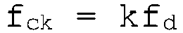
ck ) ist, fd die Oszillationsfrequenz ist, und k ein Multiplikationsfaktor ist. - Schaltung nach Anspruch 3, wobei die Zählung (N) durch den folgenden Ausdruck gegeben ist:

ck ) ist, und Ath/A0 das Verhältnis zwischen dem Amplitudenschwellenwert (Ath) und der Oszillationsamplitude (A0) ist. - Schaltung nach Anspruch 4, wobei das Verhältnis zwischen dem Amplitudenschwellenwert (Ath) und der Oszillationsamplitude (A0) und der Multiplikationsfaktor (k) anpassbar sind, um die Messauflösung zu regulieren.
- Schaltung nach einem der Ansprüche 2-5, wobei die Messstufe (22) umfasst: einen Schwellenwert-Vergleichsblock (24), der konfiguriert ist, um das Ansteuerungsdetektionssignal (VSD) mit dem Amplitudenschwellenwert (Ath) zu vergleichen und ein Time-over-Threshold Signal (SToT) zu erzeugen, das auf das Zeitintervall hinweist, in dem das Ansteuerungsdetektionssignal (VSD), in einem absoluten Wert, über dem Amplitudenschwellenwert (Ath) verbleibt; und einen Zählerblock (25), der konfiguriert ist, um die Zählung (N) basierend auf dem Time-over-Threshold Signal (SToT) durchzuführen.
- Schaltung nach einem der Ansprüche 2-6, wobei die Steuerungsstufe (19, 26) einen Digital-Analog-Wandlerblock (27) umfasst, der gestaltet ist, um das Steuersignal (Vctrl) in Abhängigkeit von einem Vergleich zwischen der Oszillationsamplitude (A0) und einem Referenzwert (Vref), die gewünschte Oszillationsamplitude der Ansteuerungsbewegung repräsentierend, zu erzeugen; und wobei das Steuersignal (Vctrl) gestaltet ist, um eine Amplitude des Ansteuerungssignals (D1, D2) zu steuern.
- Schaltung nach einem der Ansprüche 2-6, wobei die Steuerungsstufe (19, 26) einen digitalen Schieber (28) umfasst, der gestaltet ist, um in Abhängigkeit von der Zählung (N) das Steuersignal (Φctrl) als Phasenverzögerungssignal bereitzustellen; wobei das Steuersignal (Φctrl) dazu bestimmt ist, eine Phase der Ansteuerungssignale (D1, D2) zu steuern.
- Schaltung nach einem der vorstehenden Ansprüche, wobei der Schwellenwert (Ath), als absoluter Wert, größer als null und kleiner als der absolute Wert der Oszillationsamplitude (A0) ist.
- MEMS-Gyroskop (32), das auf Basis des Corioliseffekts betrieben wird, mindestens eine bewegliche Masse (2) und eine Ansteuerungsschaltung (20) nach einem der vorstehenden Ansprüche umfassend.
- Elektronische Vorrichtung (30), umfassend ein MEMS-Gyroskop (32) nach Anspruch 10, und eine elektronische Steuereinheit (34), die betrieblich an das MEMS-Gyroskop (32) gekoppelt ist.
- Ansteuerungsverfahren für ein MEMS-Gyroskop (32), das auf Basis des Corioliseffekts betrieben wird, umfassend die Lieferung von Ansteuerungssignalen (D1, D2) an eine bewegliche Masse (2) des MEMS-Gyroskops (32), um eine Ansteuerungsbewegung davon mit einer Oszillationsfrequenz (fd) zu bewirken, wobei die Lieferung umfasst:Erzeugen eines Ansteuerungsdetektionssignals (VSD) auf der Basis mindestens einer elektrischen Größe, die auf die Ansteuerungsbewegung der beweglichen Masse (2) hinweist;Messen einer Oszillationsamplitude (Ao) der Ansteuerungsbewegung in Abhängigkeit von dem Ansteuerungsdetektionssignal (VSD); undErzeugen der Ansteuerungssignale (D1, D2) auf der Basis einer Rückkopplungssteuerung der Oszillationsamplitude,dadurch gekennzeichnet, dass die Messung das Durchführen einer Messung im digitalen Bereich eines Zeitintervalls (Δt) umfasst, in dem das Ansteuerungsdetektionssignal (VSD) größer als ein Amplitudenschwellenwert (Ath) ist, und die Messung der Oszillationsamplitude (A0) in Abhängigkeit von dem Zeitintervall (Δt).
- Verfahren nach Anspruch 12, wobei das Messen das Bestimmen einer Zählung (N) der Anzahl von Perioden (Tck) eines Taktsignals (
ck ) umfasst, das auf der Basis der Oszillationsfrequenz (fd) erzeugt wird, die in dem Zeitintervall (Δt) enthalten sind. - Verfahren nach Anspruch 13, wobei das Taktsignal (
ck ) eine Frequenz (fck) aufweist, die größer als die Oszillationsfrequenz (fd) ist, die durch den folgenden Ausdruck gegeben ist:
ck ) ist, fd die Oszillationsfrequenz ist, und k ein Multiplikationsfaktor ist. - Verfahren nach Anspruch 14, wobei das Bestimmen einer Zählung das Bestimmen der Zählung (N) durch den folgenden Ausdruck umfasst:

ck ) ist, und Ath/A0 das Verhältnis zwischen dem Amplitudenschwellenwert (Ath) und der Oszillationsamplitude (A0) ist.
Applications Claiming Priority (1)
| Application Number | Priority Date | Filing Date | Title |
|---|---|---|---|
| IT102017000103058A IT201700103058A1 (it) | 2017-09-14 | 2017-09-14 | Circuito e metodo di azionamento per un giroscopio mems e relativo giroscopio mems |
Publications (2)
| Publication Number | Publication Date |
|---|---|
| EP3460397A1 EP3460397A1 (de) | 2019-03-27 |
| EP3460397B1 true EP3460397B1 (de) | 2020-09-30 |
Family
ID=60813899
Family Applications (1)
| Application Number | Title | Priority Date | Filing Date |
|---|---|---|---|
| EP18188832.2A Active EP3460397B1 (de) | 2017-09-14 | 2018-08-14 | Ansteuerungsschaltung und verfahren für ein mems-gyroskop und zugehöriges mems-gyroskop |
Country Status (4)
| Country | Link |
|---|---|
| US (2) | US10955244B2 (de) |
| EP (1) | EP3460397B1 (de) |
| CN (2) | CN109506639B (de) |
| IT (1) | IT201700103058A1 (de) |
Families Citing this family (6)
| Publication number | Priority date | Publication date | Assignee | Title |
|---|---|---|---|---|
| IT201700103058A1 (it) * | 2017-09-14 | 2019-03-14 | St Microelectronics Srl | Circuito e metodo di azionamento per un giroscopio mems e relativo giroscopio mems |
| DE102019210305A1 (de) * | 2019-07-11 | 2021-01-14 | Infineon Technologies Ag | Steuern eines Oszillationssystems |
| CN111246336B (zh) * | 2020-02-27 | 2022-03-08 | 深迪半导体(绍兴)有限公司 | 耳机和电子设备 |
| EP3882571B1 (de) * | 2020-03-16 | 2022-08-24 | Murata Manufacturing Co., Ltd. | Kreisel mit verriegelter sekundärer schwingungsfrequenz |
| IT202100016877A1 (it) * | 2021-06-28 | 2022-12-28 | St Microelectronics Srl | Circuito di pilotaggio per il controllo di un oscillatore mems di tipo risonante |
| IT202100016880A1 (it) | 2021-06-28 | 2022-12-28 | St Microelectronics Srl | Giroscopio microelettromeccanico con anello risonante di pilotaggio ad ampiezza di oscillazione controllata e metodo per controllare un giroscopio microelettromeccanico |
Family Cites Families (18)
| Publication number | Priority date | Publication date | Assignee | Title |
|---|---|---|---|---|
| US6915215B2 (en) * | 2002-06-25 | 2005-07-05 | The Boeing Company | Integrated low power digital gyro control electronics |
| JP5365173B2 (ja) * | 2008-02-29 | 2013-12-11 | セイコーエプソン株式会社 | 物理量測定装置および電子機器 |
| IT1394898B1 (it) * | 2009-06-03 | 2012-07-20 | St Microelectronics Rousset | Giroscopio microelettromeccanico con attuazione a controllo di posizione e metodo per il controllo di un giroscopio microelettromeccanico |
| US8539834B2 (en) * | 2010-02-15 | 2013-09-24 | Stmicroelectronics S.R.L. | Microelectromechanical gyroscope with calibrated synchronization of actuation and method for actuating a microelectromechanical gyroscope |
| JP5638419B2 (ja) * | 2011-02-25 | 2014-12-10 | セイコーエプソン株式会社 | 信号処理回路、物理量検出装置、角速度検出装置、集積回路装置及び電子機器 |
| ITTO20110685A1 (it) * | 2011-07-28 | 2013-01-29 | St Microelectronics Srl | Giroscopio microelettromeccanico con stadio di lettura perfezionato, e metodo |
| ITTO20110979A1 (it) * | 2011-10-27 | 2013-04-28 | St Microelectronics Srl | Circuito di pilotaggio per un giroscopio microelettromeccanico e relativo giroscopio microelettromeccanico |
| EP2647952B1 (de) * | 2012-04-05 | 2017-11-15 | Fairchild Semiconductor Corporation | Automatische Verstärkungsregelungsschleife einer MEMS-Vorrichtung für mechanischen Amplitudenantrieb |
| WO2014006437A1 (en) * | 2012-07-04 | 2014-01-09 | Freescale Semiconductor, Inc. | A digital sample clock generator, a vibration gyroscope circuitry comprising such digital sample clock generator, an associated apparatus, an associated semiconductor device and associated methods |
| US9146109B2 (en) * | 2012-11-26 | 2015-09-29 | Stmicroelectronics S.R.L. | Microelectromechanical gyroscope with improved start-up phase, system including the microelectromechanical gyroscope, and method for speeding-up the start up phase |
| US10119822B2 (en) * | 2013-11-22 | 2018-11-06 | Nxp Usa, Inc. | In-band beating removal for a MEMS gyroscope |
| DE102014003640A1 (de) * | 2014-03-14 | 2015-09-17 | Northrop Grumman Litef Gmbh | Verfahren zum optimieren der einschaltzeit eines corioliskreisels sowie dafür geeigneter corioliskreisel |
| WO2015200850A2 (en) * | 2014-06-26 | 2015-12-30 | Lumedyne Technologies Incorporated | System and methods for determining rotation from nonlinear periodic signals |
| US9644965B2 (en) * | 2014-10-09 | 2017-05-09 | Nxp Usa, Inc. | System comprising a mechanical resonator and method therefor |
| US9835454B2 (en) * | 2015-02-09 | 2017-12-05 | Invensense, Inc. | High-Q MEMS gyroscope |
| JP6589333B2 (ja) * | 2015-03-30 | 2019-10-16 | セイコーエプソン株式会社 | 回路装置、電子機器及び移動体 |
| ITUB20152221A1 (it) * | 2015-07-15 | 2017-01-15 | St Microelectronics Srl | Circuito sfasatore di 90° e relativo metodo di sfasamento di 90° |
| IT201700103058A1 (it) * | 2017-09-14 | 2019-03-14 | St Microelectronics Srl | Circuito e metodo di azionamento per un giroscopio mems e relativo giroscopio mems |
-
2017
- 2017-09-14 IT IT102017000103058A patent/IT201700103058A1/it unknown
-
2018
- 2018-08-14 EP EP18188832.2A patent/EP3460397B1/de active Active
- 2018-09-06 US US16/123,849 patent/US10955244B2/en active Active
- 2018-09-10 CN CN201811050424.3A patent/CN109506639B/zh active Active
- 2018-09-10 CN CN201821473474.8U patent/CN208847194U/zh active Active
-
2021
- 2021-02-18 US US17/179,225 patent/US11841229B2/en active Active
Non-Patent Citations (1)
| Title |
|---|
| None * |
Also Published As
| Publication number | Publication date |
|---|---|
| US11841229B2 (en) | 2023-12-12 |
| IT201700103058A1 (it) | 2019-03-14 |
| US10955244B2 (en) | 2021-03-23 |
| EP3460397A1 (de) | 2019-03-27 |
| CN109506639A (zh) | 2019-03-22 |
| US20210172738A1 (en) | 2021-06-10 |
| CN109506639B (zh) | 2023-01-31 |
| US20190078889A1 (en) | 2019-03-14 |
| CN208847194U (zh) | 2019-05-10 |
Similar Documents
| Publication | Publication Date | Title |
|---|---|---|
| EP3460397B1 (de) | Ansteuerungsschaltung und verfahren für ein mems-gyroskop und zugehöriges mems-gyroskop | |
| JP4458441B2 (ja) | 分割電極を有する音叉ジャイロ | |
| US10837796B2 (en) | Gyroscope sensitivity calibration | |
| US9588190B2 (en) | Resonant MEMS lorentz-force magnetometer using force-feedback and frequency-locked coil excitation | |
| US7444869B2 (en) | Force rebalancing and parametric amplification of MEMS inertial sensors | |
| US9869552B2 (en) | Gyroscope that compensates for fluctuations in sensitivity | |
| US20080000296A1 (en) | Force rebalancing for mems inertial sensors using time-varying voltages | |
| TWI482946B (zh) | 旋轉速率感測器用的補償電路與其補償方法 | |
| US10578435B2 (en) | Quality factor compensation in microelectromechanical system (MEMS) gyroscopes | |
| US6445195B1 (en) | Drive feedthrough nulling system | |
| US11650078B2 (en) | Demodulation phase calibration using external input | |
| US20190137272A1 (en) | Method and device for demodulating gyroscope signals | |
| JP2931712B2 (ja) | 圧電レートセンサの目盛係数の補償方法及び装置 | |
| US8327705B2 (en) | Frequency modulated micro-gyro signal processing method and device | |
| EP2733461A2 (de) | Amplitudensteuerung für vibrierende Resonanzsensoren | |
| US11662361B2 (en) | Methods for closed loop operation of capacitive accelerometers | |
| KR101829027B1 (ko) | 코리올리 자이로스코프의 스위치 온 시간의 최적화 방법 및 그에 적합한 코리올리 자이로스코프 | |
| KR100415076B1 (ko) | 각속도 검출 방법 및 진동 자이로스코프 | |
| US9224435B2 (en) | Radiation-hard precision voltage reference | |
| US11493534B1 (en) | Continuous online self-calibrating resonant FM microelectromechanical systems (MEMS) accelerometer | |
| CN111380561B (zh) | 一种基于多参数融合的微机电陀螺标度因数补偿方法 | |
| Geiger et al. | Improved Rate Gyroscope Designs Designated for Fabrication by Modern Deep Silicon Etching | |
| Shaban et al. | Analysis and design of gyro-drive mode loop with amplitude control | |
| CN116075687A (zh) | 传感器系统,用于补偿旋转速率信号的偏移的方法 | |
| RU2314495C1 (ru) | Интерфейсное устройство для микромеханического гироскопа |
Legal Events
| Date | Code | Title | Description |
|---|---|---|---|
| PUAI | Public reference made under article 153(3) epc to a published international application that has entered the european phase |
Free format text: ORIGINAL CODE: 0009012 |
|
| STAA | Information on the status of an ep patent application or granted ep patent |
Free format text: STATUS: THE APPLICATION HAS BEEN PUBLISHED |
|
| AK | Designated contracting states |
Kind code of ref document: A1 Designated state(s): AL AT BE BG CH CY CZ DE DK EE ES FI FR GB GR HR HU IE IS IT LI LT LU LV MC MK MT NL NO PL PT RO RS SE SI SK SM TR |
|
| AX | Request for extension of the european patent |
Extension state: BA ME |
|
| RIN1 | Information on inventor provided before grant (corrected) |
Inventor name: FACCHINETTI, STEFANO |
|
| STAA | Information on the status of an ep patent application or granted ep patent |
Free format text: STATUS: REQUEST FOR EXAMINATION WAS MADE |
|
| 17P | Request for examination filed |
Effective date: 20190926 |
|
| RBV | Designated contracting states (corrected) |
Designated state(s): AL AT BE BG CH CY CZ DE DK EE ES FI FR GB GR HR HU IE IS IT LI LT LU LV MC MK MT NL NO PL PT RO RS SE SI SK SM TR |
|
| GRAP | Despatch of communication of intention to grant a patent |
Free format text: ORIGINAL CODE: EPIDOSNIGR1 |
|
| STAA | Information on the status of an ep patent application or granted ep patent |
Free format text: STATUS: GRANT OF PATENT IS INTENDED |
|
| INTG | Intention to grant announced |
Effective date: 20200325 |
|
| GRAS | Grant fee paid |
Free format text: ORIGINAL CODE: EPIDOSNIGR3 |
|
| GRAA | (expected) grant |
Free format text: ORIGINAL CODE: 0009210 |
|
| STAA | Information on the status of an ep patent application or granted ep patent |
Free format text: STATUS: THE PATENT HAS BEEN GRANTED |
|
| AK | Designated contracting states |
Kind code of ref document: B1 Designated state(s): AL AT BE BG CH CY CZ DE DK EE ES FI FR GB GR HR HU IE IS IT LI LT LU LV MC MK MT NL NO PL PT RO RS SE SI SK SM TR |
|
| REG | Reference to a national code |
Ref country code: CH Ref legal event code: EP Ref country code: GB Ref legal event code: FG4D |
|
| REG | Reference to a national code |
Ref country code: AT Ref legal event code: REF Ref document number: 1319255 Country of ref document: AT Kind code of ref document: T Effective date: 20201015 |
|
| REG | Reference to a national code |
Ref country code: DE Ref legal event code: R096 Ref document number: 602018008241 Country of ref document: DE |
|
| REG | Reference to a national code |
Ref country code: IE Ref legal event code: FG4D |
|
| PG25 | Lapsed in a contracting state [announced via postgrant information from national office to epo] |
Ref country code: NO Free format text: LAPSE BECAUSE OF FAILURE TO SUBMIT A TRANSLATION OF THE DESCRIPTION OR TO PAY THE FEE WITHIN THE PRESCRIBED TIME-LIMIT Effective date: 20201230 Ref country code: SE Free format text: LAPSE BECAUSE OF FAILURE TO SUBMIT A TRANSLATION OF THE DESCRIPTION OR TO PAY THE FEE WITHIN THE PRESCRIBED TIME-LIMIT Effective date: 20200930 Ref country code: GR Free format text: LAPSE BECAUSE OF FAILURE TO SUBMIT A TRANSLATION OF THE DESCRIPTION OR TO PAY THE FEE WITHIN THE PRESCRIBED TIME-LIMIT Effective date: 20201231 Ref country code: FI Free format text: LAPSE BECAUSE OF FAILURE TO SUBMIT A TRANSLATION OF THE DESCRIPTION OR TO PAY THE FEE WITHIN THE PRESCRIBED TIME-LIMIT Effective date: 20200930 Ref country code: HR Free format text: LAPSE BECAUSE OF FAILURE TO SUBMIT A TRANSLATION OF THE DESCRIPTION OR TO PAY THE FEE WITHIN THE PRESCRIBED TIME-LIMIT Effective date: 20200930 Ref country code: BG Free format text: LAPSE BECAUSE OF FAILURE TO SUBMIT A TRANSLATION OF THE DESCRIPTION OR TO PAY THE FEE WITHIN THE PRESCRIBED TIME-LIMIT Effective date: 20201230 |
|
| REG | Reference to a national code |
Ref country code: AT Ref legal event code: MK05 Ref document number: 1319255 Country of ref document: AT Kind code of ref document: T Effective date: 20200930 |
|
| PG25 | Lapsed in a contracting state [announced via postgrant information from national office to epo] |
Ref country code: LV Free format text: LAPSE BECAUSE OF FAILURE TO SUBMIT A TRANSLATION OF THE DESCRIPTION OR TO PAY THE FEE WITHIN THE PRESCRIBED TIME-LIMIT Effective date: 20200930 Ref country code: RS Free format text: LAPSE BECAUSE OF FAILURE TO SUBMIT A TRANSLATION OF THE DESCRIPTION OR TO PAY THE FEE WITHIN THE PRESCRIBED TIME-LIMIT Effective date: 20200930 |
|
| REG | Reference to a national code |
Ref country code: NL Ref legal event code: MP Effective date: 20200930 |
|
| REG | Reference to a national code |
Ref country code: LT Ref legal event code: MG4D |
|
| PG25 | Lapsed in a contracting state [announced via postgrant information from national office to epo] |
Ref country code: LT Free format text: LAPSE BECAUSE OF FAILURE TO SUBMIT A TRANSLATION OF THE DESCRIPTION OR TO PAY THE FEE WITHIN THE PRESCRIBED TIME-LIMIT Effective date: 20200930 Ref country code: SM Free format text: LAPSE BECAUSE OF FAILURE TO SUBMIT A TRANSLATION OF THE DESCRIPTION OR TO PAY THE FEE WITHIN THE PRESCRIBED TIME-LIMIT Effective date: 20200930 Ref country code: PT Free format text: LAPSE BECAUSE OF FAILURE TO SUBMIT A TRANSLATION OF THE DESCRIPTION OR TO PAY THE FEE WITHIN THE PRESCRIBED TIME-LIMIT Effective date: 20210201 Ref country code: RO Free format text: LAPSE BECAUSE OF FAILURE TO SUBMIT A TRANSLATION OF THE DESCRIPTION OR TO PAY THE FEE WITHIN THE PRESCRIBED TIME-LIMIT Effective date: 20200930 Ref country code: CZ Free format text: LAPSE BECAUSE OF FAILURE TO SUBMIT A TRANSLATION OF THE DESCRIPTION OR TO PAY THE FEE WITHIN THE PRESCRIBED TIME-LIMIT Effective date: 20200930 Ref country code: EE Free format text: LAPSE BECAUSE OF FAILURE TO SUBMIT A TRANSLATION OF THE DESCRIPTION OR TO PAY THE FEE WITHIN THE PRESCRIBED TIME-LIMIT Effective date: 20200930 |
|
| PG25 | Lapsed in a contracting state [announced via postgrant information from national office to epo] |
Ref country code: IS Free format text: LAPSE BECAUSE OF FAILURE TO SUBMIT A TRANSLATION OF THE DESCRIPTION OR TO PAY THE FEE WITHIN THE PRESCRIBED TIME-LIMIT Effective date: 20210130 Ref country code: PL Free format text: LAPSE BECAUSE OF FAILURE TO SUBMIT A TRANSLATION OF THE DESCRIPTION OR TO PAY THE FEE WITHIN THE PRESCRIBED TIME-LIMIT Effective date: 20200930 Ref country code: ES Free format text: LAPSE BECAUSE OF FAILURE TO SUBMIT A TRANSLATION OF THE DESCRIPTION OR TO PAY THE FEE WITHIN THE PRESCRIBED TIME-LIMIT Effective date: 20200930 Ref country code: AL Free format text: LAPSE BECAUSE OF FAILURE TO SUBMIT A TRANSLATION OF THE DESCRIPTION OR TO PAY THE FEE WITHIN THE PRESCRIBED TIME-LIMIT Effective date: 20200930 Ref country code: AT Free format text: LAPSE BECAUSE OF FAILURE TO SUBMIT A TRANSLATION OF THE DESCRIPTION OR TO PAY THE FEE WITHIN THE PRESCRIBED TIME-LIMIT Effective date: 20200930 |
|
| PG25 | Lapsed in a contracting state [announced via postgrant information from national office to epo] |
Ref country code: NL Free format text: LAPSE BECAUSE OF FAILURE TO SUBMIT A TRANSLATION OF THE DESCRIPTION OR TO PAY THE FEE WITHIN THE PRESCRIBED TIME-LIMIT Effective date: 20200930 Ref country code: SK Free format text: LAPSE BECAUSE OF FAILURE TO SUBMIT A TRANSLATION OF THE DESCRIPTION OR TO PAY THE FEE WITHIN THE PRESCRIBED TIME-LIMIT Effective date: 20200930 |
|
| REG | Reference to a national code |
Ref country code: DE Ref legal event code: R097 Ref document number: 602018008241 Country of ref document: DE |
|
| PLBE | No opposition filed within time limit |
Free format text: ORIGINAL CODE: 0009261 |
|
| STAA | Information on the status of an ep patent application or granted ep patent |
Free format text: STATUS: NO OPPOSITION FILED WITHIN TIME LIMIT |
|
| PG25 | Lapsed in a contracting state [announced via postgrant information from national office to epo] |
Ref country code: DK Free format text: LAPSE BECAUSE OF FAILURE TO SUBMIT A TRANSLATION OF THE DESCRIPTION OR TO PAY THE FEE WITHIN THE PRESCRIBED TIME-LIMIT Effective date: 20200930 |
|
| 26N | No opposition filed |
Effective date: 20210701 |
|
| PG25 | Lapsed in a contracting state [announced via postgrant information from national office to epo] |
Ref country code: IT Free format text: LAPSE BECAUSE OF FAILURE TO SUBMIT A TRANSLATION OF THE DESCRIPTION OR TO PAY THE FEE WITHIN THE PRESCRIBED TIME-LIMIT Effective date: 20200930 |
|
| PG25 | Lapsed in a contracting state [announced via postgrant information from national office to epo] |
Ref country code: SI Free format text: LAPSE BECAUSE OF FAILURE TO SUBMIT A TRANSLATION OF THE DESCRIPTION OR TO PAY THE FEE WITHIN THE PRESCRIBED TIME-LIMIT Effective date: 20200930 |
|
| REG | Reference to a national code |
Ref country code: CH Ref legal event code: PL |
|
| PG25 | Lapsed in a contracting state [announced via postgrant information from national office to epo] |
Ref country code: MC Free format text: LAPSE BECAUSE OF FAILURE TO SUBMIT A TRANSLATION OF THE DESCRIPTION OR TO PAY THE FEE WITHIN THE PRESCRIBED TIME-LIMIT Effective date: 20200930 |
|
| REG | Reference to a national code |
Ref country code: BE Ref legal event code: MM Effective date: 20210831 |
|
| PG25 | Lapsed in a contracting state [announced via postgrant information from national office to epo] |
Ref country code: LI Free format text: LAPSE BECAUSE OF NON-PAYMENT OF DUE FEES Effective date: 20210831 Ref country code: CH Free format text: LAPSE BECAUSE OF NON-PAYMENT OF DUE FEES Effective date: 20210831 |
|
| PG25 | Lapsed in a contracting state [announced via postgrant information from national office to epo] |
Ref country code: IS Free format text: LAPSE BECAUSE OF FAILURE TO SUBMIT A TRANSLATION OF THE DESCRIPTION OR TO PAY THE FEE WITHIN THE PRESCRIBED TIME-LIMIT Effective date: 20210130 Ref country code: LU Free format text: LAPSE BECAUSE OF NON-PAYMENT OF DUE FEES Effective date: 20210814 |
|
| PG25 | Lapsed in a contracting state [announced via postgrant information from national office to epo] |
Ref country code: IE Free format text: LAPSE BECAUSE OF NON-PAYMENT OF DUE FEES Effective date: 20210814 Ref country code: FR Free format text: LAPSE BECAUSE OF NON-PAYMENT OF DUE FEES Effective date: 20210831 Ref country code: BE Free format text: LAPSE BECAUSE OF NON-PAYMENT OF DUE FEES Effective date: 20210831 |
|
| GBPC | Gb: european patent ceased through non-payment of renewal fee |
Effective date: 20220814 |
|
| PG25 | Lapsed in a contracting state [announced via postgrant information from national office to epo] |
Ref country code: CY Free format text: LAPSE BECAUSE OF FAILURE TO SUBMIT A TRANSLATION OF THE DESCRIPTION OR TO PAY THE FEE WITHIN THE PRESCRIBED TIME-LIMIT Effective date: 20200930 |
|
| PG25 | Lapsed in a contracting state [announced via postgrant information from national office to epo] |
Ref country code: HU Free format text: LAPSE BECAUSE OF FAILURE TO SUBMIT A TRANSLATION OF THE DESCRIPTION OR TO PAY THE FEE WITHIN THE PRESCRIBED TIME-LIMIT; INVALID AB INITIO Effective date: 20180814 |
|
| PG25 | Lapsed in a contracting state [announced via postgrant information from national office to epo] |
Ref country code: GB Free format text: LAPSE BECAUSE OF NON-PAYMENT OF DUE FEES Effective date: 20220814 |
|
| PGFP | Annual fee paid to national office [announced via postgrant information from national office to epo] |
Ref country code: DE Payment date: 20230720 Year of fee payment: 6 |
|
| PG25 | Lapsed in a contracting state [announced via postgrant information from national office to epo] |
Ref country code: MK Free format text: LAPSE BECAUSE OF FAILURE TO SUBMIT A TRANSLATION OF THE DESCRIPTION OR TO PAY THE FEE WITHIN THE PRESCRIBED TIME-LIMIT Effective date: 20200930 |