EP3460396B1 - Survey system - Google Patents
Survey system Download PDFInfo
- Publication number
- EP3460396B1 EP3460396B1 EP18193950.5A EP18193950A EP3460396B1 EP 3460396 B1 EP3460396 B1 EP 3460396B1 EP 18193950 A EP18193950 A EP 18193950A EP 3460396 B1 EP3460396 B1 EP 3460396B1
- Authority
- EP
- European Patent Office
- Prior art keywords
- scanner
- unit
- surveying
- prism
- camera
- Prior art date
- Legal status (The legal status is an assumption and is not a legal conclusion. Google has not performed a legal analysis and makes no representation as to the accuracy of the status listed.)
- Active
Links
Images


Classifications
-
- G—PHYSICS
- G01—MEASURING; TESTING
- G01C—MEASURING DISTANCES, LEVELS OR BEARINGS; SURVEYING; NAVIGATION; GYROSCOPIC INSTRUMENTS; PHOTOGRAMMETRY OR VIDEOGRAMMETRY
- G01C11/00—Photogrammetry or videogrammetry, e.g. stereogrammetry; Photographic surveying
- G01C11/02—Picture taking arrangements specially adapted for photogrammetry or photographic surveying, e.g. controlling overlapping of pictures
-
- B—PERFORMING OPERATIONS; TRANSPORTING
- B64—AIRCRAFT; AVIATION; COSMONAUTICS
- B64D—EQUIPMENT FOR FITTING IN OR TO AIRCRAFT; FLIGHT SUITS; PARACHUTES; ARRANGEMENT OR MOUNTING OF POWER PLANTS OR PROPULSION TRANSMISSIONS IN AIRCRAFT
- B64D47/00—Equipment not otherwise provided for
- B64D47/08—Arrangements of cameras
-
- G—PHYSICS
- G01—MEASURING; TESTING
- G01C—MEASURING DISTANCES, LEVELS OR BEARINGS; SURVEYING; NAVIGATION; GYROSCOPIC INSTRUMENTS; PHOTOGRAMMETRY OR VIDEOGRAMMETRY
- G01C11/00—Photogrammetry or videogrammetry, e.g. stereogrammetry; Photographic surveying
- G01C11/04—Interpretation of pictures
- G01C11/30—Interpretation of pictures by triangulation
-
- G—PHYSICS
- G01—MEASURING; TESTING
- G01C—MEASURING DISTANCES, LEVELS OR BEARINGS; SURVEYING; NAVIGATION; GYROSCOPIC INSTRUMENTS; PHOTOGRAMMETRY OR VIDEOGRAMMETRY
- G01C15/00—Surveying instruments or accessories not provided for in groups G01C1/00 - G01C13/00
- G01C15/002—Active optical surveying means
-
- G—PHYSICS
- G01—MEASURING; TESTING
- G01S—RADIO DIRECTION-FINDING; RADIO NAVIGATION; DETERMINING DISTANCE OR VELOCITY BY USE OF RADIO WAVES; LOCATING OR PRESENCE-DETECTING BY USE OF THE REFLECTION OR RERADIATION OF RADIO WAVES; ANALOGOUS ARRANGEMENTS USING OTHER WAVES
- G01S17/00—Systems using the reflection or reradiation of electromagnetic waves other than radio waves, e.g. lidar systems
- G01S17/02—Systems using the reflection of electromagnetic waves other than radio waves
- G01S17/06—Systems determining position data of a target
- G01S17/42—Simultaneous measurement of distance and other co-ordinates
-
- G—PHYSICS
- G01—MEASURING; TESTING
- G01S—RADIO DIRECTION-FINDING; RADIO NAVIGATION; DETERMINING DISTANCE OR VELOCITY BY USE OF RADIO WAVES; LOCATING OR PRESENCE-DETECTING BY USE OF THE REFLECTION OR RERADIATION OF RADIO WAVES; ANALOGOUS ARRANGEMENTS USING OTHER WAVES
- G01S17/00—Systems using the reflection or reradiation of electromagnetic waves other than radio waves, e.g. lidar systems
- G01S17/66—Tracking systems using electromagnetic waves other than radio waves
-
- G—PHYSICS
- G01—MEASURING; TESTING
- G01S—RADIO DIRECTION-FINDING; RADIO NAVIGATION; DETERMINING DISTANCE OR VELOCITY BY USE OF RADIO WAVES; LOCATING OR PRESENCE-DETECTING BY USE OF THE REFLECTION OR RERADIATION OF RADIO WAVES; ANALOGOUS ARRANGEMENTS USING OTHER WAVES
- G01S17/00—Systems using the reflection or reradiation of electromagnetic waves other than radio waves, e.g. lidar systems
- G01S17/86—Combinations of lidar systems with systems other than lidar, radar or sonar, e.g. with direction finders
-
- G—PHYSICS
- G01—MEASURING; TESTING
- G01S—RADIO DIRECTION-FINDING; RADIO NAVIGATION; DETERMINING DISTANCE OR VELOCITY BY USE OF RADIO WAVES; LOCATING OR PRESENCE-DETECTING BY USE OF THE REFLECTION OR RERADIATION OF RADIO WAVES; ANALOGOUS ARRANGEMENTS USING OTHER WAVES
- G01S17/00—Systems using the reflection or reradiation of electromagnetic waves other than radio waves, e.g. lidar systems
- G01S17/87—Combinations of systems using electromagnetic waves other than radio waves
-
- G—PHYSICS
- G01—MEASURING; TESTING
- G01S—RADIO DIRECTION-FINDING; RADIO NAVIGATION; DETERMINING DISTANCE OR VELOCITY BY USE OF RADIO WAVES; LOCATING OR PRESENCE-DETECTING BY USE OF THE REFLECTION OR RERADIATION OF RADIO WAVES; ANALOGOUS ARRANGEMENTS USING OTHER WAVES
- G01S17/00—Systems using the reflection or reradiation of electromagnetic waves other than radio waves, e.g. lidar systems
- G01S17/88—Lidar systems specially adapted for specific applications
- G01S17/89—Lidar systems specially adapted for specific applications for mapping or imaging
-
- G—PHYSICS
- G05—CONTROLLING; REGULATING
- G05D—SYSTEMS FOR CONTROLLING OR REGULATING NON-ELECTRIC VARIABLES
- G05D1/00—Control of position, course, altitude or attitude of land, water, air or space vehicles, e.g. using automatic pilots
- G05D1/0094—Control of position, course, altitude or attitude of land, water, air or space vehicles, e.g. using automatic pilots involving pointing a payload, e.g. camera, weapon, sensor, towards a fixed or moving target
-
- B—PERFORMING OPERATIONS; TRANSPORTING
- B64—AIRCRAFT; AVIATION; COSMONAUTICS
- B64U—UNMANNED AERIAL VEHICLES [UAV]; EQUIPMENT THEREFOR
- B64U10/00—Type of UAV
- B64U10/10—Rotorcrafts
- B64U10/13—Flying platforms
-
- B—PERFORMING OPERATIONS; TRANSPORTING
- B64—AIRCRAFT; AVIATION; COSMONAUTICS
- B64U—UNMANNED AERIAL VEHICLES [UAV]; EQUIPMENT THEREFOR
- B64U2101/00—UAVs specially adapted for particular uses or applications
- B64U2101/30—UAVs specially adapted for particular uses or applications for imaging, photography or videography
- B64U2101/31—UAVs specially adapted for particular uses or applications for imaging, photography or videography for surveillance
-
- B—PERFORMING OPERATIONS; TRANSPORTING
- B64—AIRCRAFT; AVIATION; COSMONAUTICS
- B64U—UNMANNED AERIAL VEHICLES [UAV]; EQUIPMENT THEREFOR
- B64U2201/00—UAVs characterised by their flight controls
- B64U2201/10—UAVs characterised by their flight controls autonomous, i.e. by navigating independently from ground or air stations, e.g. by using inertial navigation systems [INS]
- B64U2201/104—UAVs characterised by their flight controls autonomous, i.e. by navigating independently from ground or air stations, e.g. by using inertial navigation systems [INS] using satellite radio beacon positioning systems, e.g. GPS
Definitions
- the present invention relates to a survey system that acquires three-dimensional data of a survey site.
- Patent Literature 1 discloses a survey system that, by using a mobile body equipped with a camera and a prism, and a total station (an electronic distance measuring and angle measuring instrument, hereinafter, referred to as a surveying instrument), performs a photographic survey by identifying a photographing position of the camera by tracking the prism by the surveying instrument.
- a surveying instrument an electronic distance measuring and angle measuring instrument
- Patent Literature 2 discloses a flying vehicle has a retro-reflector, a position measuring instrument has a non-prism measurement function for performing a distance measurement and an angle measurement in non-prism and a prism measurement function for performing the distance measurement and the angle measurement with respect to the retro-reflector, a control device is adapted to have a flight range as set within a flat plane, to prepare an approximate flight plan having a two-dimensional approximate flying route as set within the flight range, to measure the approximate flying route by the non-prism measurement, to calculate a three-dimensional detailed flying route based on the measurement results and the approximate flying route, to prepare a detailed flight plan including the detailed flying route and to control the flying vehicle so as to fly in maintaining a distance between the flying vehicle system and a surface of the object to be measured at a constant value based on the detailed flight plan and a result of the prism measurement.
- Patent Literature 3 Additional relevant state of the art for the present invention is disclosed in Patent Literature 3 and Patent Literature 4
- the present invention is defined in claim 1.
- a survey system as defined in claim 1 comprises a surveying moving device and a surveying instrument, wherein the surveying moving device includes: a mobile body; a scanner including an emitting unit configured to emit a distance measuring light, a light receiving unit configured to receive a reflected distance measuring light, a distance measuring unit configured to perform a distance measurement based on an output of the light receiving unit, a first optical axis deflecting unit disposed on an optical axis of the distance measuring light and configured to deflect the distance measuring light, a second optical axis deflecting unit disposed on a light receiving optical axis of the reflected distance measuring light and configured to deflect the reflected distance measuring light at the same angle in the same direction as those of the first optical axis deflecting unit, and an emitting direction detecting unit configured to detect a deflection angle and a direction of the first optical axis deflecting unit and the second optical axis deflecting unit
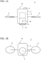
- FIGS. 1 are configuration diagrams of a survey system 1 according to a first example, FIG. 1A is a side view of the same system 1, and FIG. 1B is a bottom view of the same system.
- the survey system 1 is a surveying moving device 10 including a mobile body 2, a scanner 3, a GPS device 4, and an IMU 5.
- the mobile body 2 is a UAV (Unmanned Air Vehicle) capable of autonomous flying.
- the mobile body 2 includes a plurality of propellers 6 extending radially and a flying unit not illustrated in the drawings, and can fly along a flight path determined in advance, and can freely fly by being remotely controlled.
- the GPS device 4 is fixed to the mobile body 2, and receives a signal from a GPS satellite and acquires a UTC, a latitude, and a longitude.
- the GPS device 4 functions as a position measuring device to measure a position of the scanner 3.
- the IMU (Inertial Measurement Unit) 5 is incorporated in the mobile body 2, includes a 3-axis gyro and a 3-axis acceleration sensor, and acquires angular velocities and accelerations in 3-axis directions (roll, pitch, and yaw) of the scanner 3.
- the IMU 5 functions as a posture detecting device to detect a posture of the scanner 3.
- the scanner 3 transmits a laser distance measuring light to measure a three-dimensional position of each scanning point.
- an optical axis deflecting unit including Risley prisms is disposed, and can deflect the distance measuring light in an arbitrary direction.
- a reference optical axis O of the scanner 3 is provided so as to be positioned vertically downward when the mobile body 2 is in a horizontal posture (refer to FIG. 1A ).
- the reference sign 3o denotes a measurement reference point of the scanner 3 on the reference optical axis O.
- FIG. 2 is a configuration block diagram of the scanner 3.
- the scanner 3 includes an emitting unit 3a, a light receiving unit 3b, a distance measuring unit 3c, a scanning arithmetic unit 3d, and an emitting direction detecting unit 3m.
- the emitting unit 3a includes a light emitting element 3e and a pair of Risley prisms 3f and 3g. From the light emitting element 3e, a distance measuring light 3h' is emitted.
- the Risley prisms 3f and 3g face each other while centering on an optical axis 3h of the distance measuring light, and can be rotated independently of each other by a motor driver 3n.
- the Risley prisms 3f and 3g function as a first optical axis deflecting unit to deflect the distance measuring light 3h'.
- the light receiving unit 3b includes a light receiving element 3i and a pair of Fresnel prisms 3j and 3k including a plurality of Risley prisms continuous with each other.
- the light receiving element 3i receives a reflected distance measuring light from a scanning point.
- the Fresnel prisms 3j and 3k face each other while centering on an optical axis 3l of the reflected measuring light 3l', and can be rotated independently of each other by the motor driver 3n.
- the Fresnel prisms 3j and 3k function as a second optical axis deflecting unit to deflect the reflected distance measuring light 3l'.
- the first optical axis deflecting unit is disposed on an emission side
- the second optical axis deflecting unit is disposed on a light receiving side, however, a configuration in which an optical axis deflecting unit is shared by the emission side and the light receiving side may be adopted.
- the distance measuring unit 3c transmits a distance measuring light 3h', and acquires a distance to each scanning point by measuring a round-trip time of the distance measuring light 3h' based on a light receiving signal of the light receiving element 3i.
- the emitting direction detecting unit 3m counts drive pulses input to the motor driver 3n or uses an encoder to detect rotation directions, rotation amounts, and rotation speeds of the Risley prisms 3f and 3g. By passing through the Risley prisms 3f and 3g, the distance measuring light 3h' is deflected in an arbitrary direction.
- the scanning arithmetic unit 3d obtains refractive indexes and rotation angles of the Risley prisms 3f and 3g from the emitting direction detecting unit 3m, and based on these, calculates a deflection angle and direction of the distance measuring light 3h'.
- the emitting direction detecting unit 3m detects rotation directions, rotation amounts, and rotation speeds of the Fresnel prisms 3j and 3k in the same manner.
- the scanning arithmetic unit 3d performs control so that the deflection angles and directions of the Fresnel prisms 3j and 3k are always the same as those of the Risley prisms 3f and 3g.
- the reflected distance measuring light 3l' is deflected so as to match the light receiving optical axis 3l.
- the scanner 3 can arbitrarily deflect the deflection angle and direction of the distance measuring light 3h' in accordance with a combination of rotational positions of the Risley prisms 3f and 3g, and acquire three-dimensional point group data of scanning points.
- the distance measuring light 3h' can be scanned, for example, in a circular form around a deflection reference axis O' (refer to FIG. 3 described below).
- FIG. 3 is a control block diagram of the survey system 1.
- the survey system 1 includes the above-described scanner 3, GPS device 4, and IMU 5, and an arithmetic control unit 7 and an operation unit 8. From the operation unit 8, various operation commands and settings can be input to the arithmetic control unit 7.
- the arithmetic control unit 7 is, for example, a microcontroller including a CPU, a ROM, and a RAM, etc., mounted on an integrated circuit.
- the arithmetic control unit 7 controls a flying unit not illustrated in the drawings, and acquires three-dimensional point group data (distances and angles to scanning points) from the scanner 3, acquires positional information (a latitude and a longitude) of the scanner 3 from the GPS device 4, and acquires posture information (a roll angle, a pitch angle, and a yaw angle) of the scanner 3 from the IMU 5.
- To each of the three-dimensional point group data and the positional information and posture information of the scanner at the timing of outputting a light transmission signal of the scanner 3, time information by the GPS device 4 is provided.
- the arithmetic control unit 7 Based on the time information, the arithmetic control unit 7 records the three-dimensional point group data obtained by the scanner 3, the positional information of the scanner obtained by the GPS device 4, and the posture information of the scanner obtained by the IMU 5 in association with each other.
- the arithmetic control unit 7 further includes a scanning position correcting unit 7A that corrects a three-dimensional position obtained by the scanner 3 by a position and a posture of the scanner. This is described in detail below.
- Step S101 the arithmetic control unit 7 of the survey system 1 acquires a three-dimensional position (absolute coordinates) from the GPS device 4.
- the GPS device 4 and the scanner 3 are integrated together, so that positional information acquired by the GPS device 4 can be regarded as a position of the scanner.
- Step S102 in parallel with Step S101, the scanner 3 performs a distance measurement and an angle measurement to measure a three-dimensional position of each scanning point.
- Step S103 in parallel with Steps S101 and S102, the IMU 5 detects a posture (a roll angle, a pitch angle, and a yaw angle) of the scanner.
- a position of the scanner 3 is acquired as absolute coordinates in Step S101.
- an inclination (posture) of the scanner 3 is known. Therefore, the scanning position correcting unit 7A corrects the reference optical axis O of the scanner to a posture direction of the scanner, and re-calculates a distance and an angle to each scanning point measured by the scanner 3 by setting the coordinates obtained by the GPS device 4 as a measurement reference point 3o of the scanner.
- Step S105 the arithmetic control unit 7 stores the three-dimensional positions (absolute coordinates) of the scanning points corrected in Step S104, and ends the operation.
- the scanner 3 laser scanner
- the scanner 3 so that data omission due to an illuminance does not occur in a product of a three-dimensional survey.
- the distance measuring light 3h' can be freely deflected by the scanner 3, so that by rotating the distance measuring light 3h' at a high speed, two-dimensional circular scanning as illustrated in FIG. 5A can be performed (the arrow in the figure illustrates an advancing direction of the mobile body 2).
- the arrow in the figure illustrates an advancing direction of the mobile body 2.
- three-dimensional point group data of random points can be obtained, so that plants, etc., in the survey site can also be measured.
- FIG. 5B three-dimensional point group data of random points
- the scanner 3 can irradiate a distance measuring light onto not only an upper surface 52 but also a side surface 51 of the structure as compared with a line scanner that irradiates a distance measuring light onto only the upper surface 52 of the structure (one-dimensional scanning). Therefore, at the time of a three-dimensional survey of a survey site, data omission in a product of the survey can be reduced.
- the above-described scanning is just an example, and the scanner 3 can perform line scanning and other arbitrary scanning.
- FIG. 6 is an entire configuration diagram of a survey system 1' according to a second example
- FIGS. 7 are configuration diagrams of a surveying moving device of the survey system 1'
- FIG. 7A is a side view of the same device
- FIG. 7B is a bottom view of the same device.
- the survey system 1' includes a surveying moving device 10' and a surveying instrument 20.
- the surveying moving device 10' includes the mobile body 2, the scanner 3, the IMU 5, and a prism 9 that becomes a target of the surveying instrument 20.
- the prism 9 is fixed to a lateral side of a tip end of a lens portion of the scanner 3.
- the fixation position of the prism 9 may be a position other than this, however, deviations (dr, dp, and dy) in roll axis, pitch axis, and yaw axis directions between the measurement reference point 3o of the scanner and an optical center (optical reflection point) 9o of the prism 9 are made known in advance of attachment of the prism 9.
- the surveying instrument 20 is a total station capable of automatically tracking a target, and includes a main body 20a that rotates horizontally, and a telescope 20b provided vertically rotatably on the main body 20a ( FIG. 6 ).
- the surveying instrument 20 is mounted at a known point by using a tripod.
- the surveying instrument 20 functions as a position measuring device to measure a position of the scanner 3.
- FIG. 8 is a control block diagram of the survey system 1'.
- the surveying moving device 10' includes the scanner 3, the IMU 5, the arithmetic control unit 7, the operation unit 8, a communication unit 11, and a timer 12.
- the arithmetic control unit 7 acquires three-dimensional point group data (distances and angles to scanning points) from the scanner 3, and acquires posture information (a roll angle, a pitch angle, and a yaw angle) of the scanner 3 from the IMU 5.
- the arithmetic control unit 7 acquires a system time from the timer 12 at the timing of outputting a light transmission signal of the scanner 3, and provides the time to the three-dimensional point group data and the posture information of the scanner.
- the scanning position correcting unit 7A corrects a three-dimensional position obtained by the scanner 3 by a position and posture of the scanner. This is described in detail below.
- the surveying instrument 20 includes a horizontal angle detector 21, a vertical angle detector 22, a horizontal rotation drive unit 23, a vertical rotation drive unit 24, a display unit 25, an operation unit 26, an arithmetic control unit 27, a tracking unit 28, a distance measuring unit 29, a storage unit 30, a communication unit 31, and a timer 32.
- the horizontal rotation drive unit 23 and the vertical rotation drive unit 24 are motors, and are controlled by the arithmetic control unit 27 and respectively drive a horizontal rotary shaft and a vertical rotary shaft.
- the display unit 25 and the operation unit 26 are interfaces of the surveying instrument 20, and through these, commanding and setting of a survey work and confirmation of a work situation and measurement results can be performed.
- the horizontal angle detector 21 and the vertical angle detector 22 are absolute encoders or incremental encoders.
- the horizontal angle detector 21 is provided for the horizontal rotary shaft and detects a rotation angle in the horizontal direction of the main body 20a.
- the vertical angle detector 22 is provided for the vertical rotary shaft and detects a rotation angle in the vertical direction of the telescope 20b.
- the tracking unit 28 includes a tracking light transmission system that emits, as a tracking light, an infrared laser or the like with a wavelength different from that of a distance measuring light, and a tracking light receiving system including an image sensor such as a CCD sensor or a CMOS sensor.
- the tracking unit 28 acquires a landscape image including a tracking light and a landscape image from which the tracking light is excluded, and transmits both of these images to the arithmetic control unit 27.
- the arithmetic control unit 27 obtains a center of a target image from a difference between these images, detects a position at which a deviation between the center of the target image and a center of a visual axis of the telescope 20b falls within a certain value as the position of a target, and performs automatic tracking so that the telescope 20b always faces the target.
- the distance measuring unit 29 includes a distance measuring light transmission system that emits a distance measuring light such as an infrared laser to a target, and a distance measuring light receiving system that receives a reflected distance measuring light by a photodiode, etc.
- the distance measuring unit 29 receives a reflected distance measuring light from a target by the distance measuring light receiving system and divides and receives a part of the distance measuring light as an internal reference light, and measures a distance to the target based on a phase difference between the reflected distance measuring light and the internal reference light.
- the distance measuring unit measures an angle to the target from detected values of the horizontal angle detector 21 and the vertical angle detector 22.
- the arithmetic control unit 27 is, for example, a microcontroller including a CPU, a ROM, and a RAM, etc., mounted on an integrated circuit, and controls the rotation drive units 23 and 24 and controls the distance measuring unit 29 and the tracking unit 28.
- the arithmetic control unit 27 acquires a system time from the timer 32 at the timing of outputting a light transmission signal of the distance measuring unit 29, and provides the time to the distance measurement and angle measurement values.
- the storage unit 30 is, for example, a hard disk drive, and stores various programs for the arithmetic control described above.
- a target position (distance and angle) acquired by the distance measuring unit 29 is stored together with time information in the storage unit 30.
- the communication unit 31 can make wireless communication with the communication unit 11 of the surveying moving device 10', and transmits the target position stored in the storage unit 30 to the surveying moving device 10' under control of the arithmetic control unit 27.
- Step S201 the surveying instrument 20 starts automatic tracking of the prism 9 of the surveying moving device 10'.
- Step S202 the surveying instrument 20 measures a distance and an angle to an automatically tracked position by the distance measuring unit 20 to measure a three-dimensional position (absolute coordinates) of the prism 9.
- the surveying instrument 20 transmits the three-dimensional position of the prism 9 to the surveying moving device 10'.
- Step S203 in parallel with Steps S201 and S202, the surveying moving device 10' performs a distance measurement and an angle measurement by the scanner 3 to measure three-dimensional positions of scanning points.
- Step S204 in parallel with Steps S201 to S203, the surveying moving device 10' detects a posture (a roll angle, a pitch angle, and a yaw angle) of the scanner from the IMU 5.
- a posture a roll angle, a pitch angle, and a yaw angle
- Step S205 the arithmetic control unit 7 of the surveying moving device 10' associates the positional information of the prism 9 obtained from the surveying instrument 20 in Step S202, the three-dimensional point group data of the scanning points obtained from the scanner 3 in Step S203, and the posture information of the scanner obtained from the IMU 5 in Step S204 with each other by time. Then, the scanning position correcting unit 7A corrects the three-dimensional positions of the scanning points obtained in Step S203 by the position and posture of the scanner.
- Step S202 the position of the prism 9 is precisely measured as absolute coordinates by the surveying instrument 20.
- Step S204 an inclination (posture) of the scanner 3 is known. Therefore, the scanning position correcting unit 7A corrects the reference optical axis O of the scanner to a posture direction of the scanner, and re-calculates a distance and an angle to each scanning point measured by the scanner 3 by setting coordinates moved by the respective deviations (dr, dp, dy) from the coordinates of the prism 9 as a measurement reference point 3o of the scanner.
- Step S206 the measuring moving device 10' stores the three-dimensional positions (absolute coordinates) of the scanning points corrected in Step S205, and ends the operation.
- a position of the scanner 3 (measurement reference point 3o of the scanner) can be accurately obtained with use of the surveying instrument 20, so that accuracy of the three-dimensional point group data can be further improved.
- FIGS. 10 are configuration diagrams of a surveying moving device 10" according to a embodiment, and FIG. 10A is a side view of the same device, and FIG. 10B is a bottom view of the same device.
- FIG. 11 is a control block diagram of the survey system 1".
- the survey system 1" includes the surveying moving device 10" and the surveying instrument 20.
- the surveying moving device 10" includes the mobile body 2, the scanner 3, the prism 9, and a camera 13 in place of the IMU 5.
- the prism 9 is fixed to a lateral side of a tip end of a lens portion of the scanner 3 as in the second example. Deviations (dr, dp, dy) in the roll axis direction, the pitch axis direction, and the yaw axis direction between the measurement reference point 3o of the scanner 3 and the optical center 9o of the prism 9 are made known in advance of attachment of the prism 9.
- the camera 13 is an image sensor such as a CCD sensor or a CMOS sensor, and a position of each pixel on an imaging element can be identified. For example, a position of each pixel on an image is identified by a coordinate system using an imaging optical axis O" of the camera 13 as an origin.
- the camera 13 is incorporated in the mobile body 2, and is fixed so as to be displaced from the mechanism of the scanner 3.
- the imaging optical axis O" of the camera 13 is set so as to be positioned vertically downward when the mobile body 2 is in a horizontal posture (refer to FIG. 10B ).
- the camera 13 functions as a posture detecting device to detect a posture of the scanner 3.
- a control system of the survey system 1" includes, as illustrated in FIG. 11 , on the surveying moving device 10" side, the scanner 3, the arithmetic control unit 7, the operation unit 8, the communication unit 11, the timer 12, and the camera 13.
- the arithmetic control unit 7 acquires three-dimensional point group data (distances and angles to scanning points) from the scanner 3, and acquires image data from the camera 13.
- the arithmetic control unit 7 acquires a system time from the timer 12 at the timing of outputting a light transmission signal of the scanner 3, and provides the time to the three-dimensional point group data and the image data.
- the scanning position correcting unit 7A corrects a three-dimensional position obtained by the scanner 3 by a position and posture of the scanner. This is described in detail below.
- a control system on the surveying instrument 20 is the same as in the second example.
- Step S301 the surveying instrument 20 starts automatic tracking of the prism 9 of the surveying moving device 10".
- Step S302 the surveying instrument 20 measures a distance and an angle to an automatically tracked position by the distance measuring unit 29 to measure a three-dimensional position (absolute coordinates) of the prism 9.
- the surveying instrument 20 transmits the three-dimensional position of the prism 9 to the surveying moving device 10".
- Step S303 in parallel with Steps S301 and S302, the surveying moving device 10" performs a distance measurement and an angle measurement by the scanner 3 to measure three-dimensional positions of scanning points.
- Step S304 in parallel with Steps S301 to S303, the surveying moving device 10" acquires image data by the camera 13.
- the arithmetic control unit 7 of the surveying moving device 10" photographically analyzes the image data to detect a posture (a roll angle, a pitch angle, and a yaw angle) of the camera 13.
- the camera 13 and the scanner 3 are integrated together, so that the posture of the camera 13 can be regarded as a posture of the scanner 3.
- Step S305 the arithmetic control unit 7 associates the positional information of the prism 9 obtained from the surveying instrument 20 in Step S302, the three-dimensional point group data of scanning points obtained from the scanner 3 in Step S303, and the posture information of the scanner obtained through the photographic analysis in Step S304 with each other by time. Then, the scanning position correcting unit 7A corrects the three-dimensional positions of the scanning points obtained in Step S303 by the position and posture of the scanner.
- Step S302 a position of the prism 9 is precisely measured as absolute coordinates by the surveying instrument 20.
- Step S304 an inclination (posture) of the scanner 3 is known. Therefore, the scanning position correcting unit 7A corrects the reference optical axis O of the scanner to a posture direction of the scanner, and re-calculates a distance and an angle to each scanning point measured by the scanner 3 by setting coordinates moved by the deviations (dr, dp, dy) from the coordinates of the prism 9 as a measurement reference point 3o of the scanner.
- the surveying moving device 10 stores the three-dimensional positions (absolute coordinates) of the scanning points corrected in Step S305, and ends the operation.
- the system can be more inexpensively configured than in the case using a precision IMU.
- the surveying moving device 10', 10" and the surveying instrument 20 respectively include the timer 12 and the timer 32 for time synchronization, however, accurate time synchronization is preferably performed by the configuration described below.
- An example is shown by using the second example.
- FIG. 13 illustrates a modification of the survey system 1' according to the second example.
- the surveying moving device 10' includes a GPS time unit 14 in place of the timer 12, and further includes a time synchronizing unit 15.
- the surveying instrument 20 includes a GPS time unit 33 in place of the timer 32.
- Each of the GPS time unit 14 and the GPS time unit 33 includes a clock that receives a signal from a GPS satellite and generates a UTC and a PPS signal being a constant-frequency pulse.
- the GPS time unit 14 provides a first time to the three-dimensional point group data and the posture information of the scanner at the timing of outputting a light transmission signal of the scanner 3.
- the GPS time unit 33 provides a second time to the distance measurement and angle measurement values of the prism 9 at the timing of outputting a light transmission signal of the distance measuring unit 29.
- the time synchronizing unit 15 acquires the three-dimensional point group data given the first time from the arithmetic control unit 7, and acquires the distance measurement and angle measurement values of the prism 9 given the second time via the communication unit 11.
- the time synchronizing unit 15 extracts distance measurement and angle measurement values and three-dimensional point group data which are provided with a first time and a second time, respectively, matching each other, and associates the extracted distance measurement and angle measurement values of the prism 9 and the extracted three-dimensional point group data with each other.
- a second time just before a certain first time and a second time just after the certain first time are extracted, and distance measurement and angle measurement values at a second time are calculated by interpolation.
- the above-described time synchronization can also be applied in a case where the survey period is longer (lower in frequency) than the scanning period.
- the mobile bodies 2 of the surveying moving device 10', 10" is a UAV, however, the mobile body 2 is only required to be movable in a survey site.
- FIG. 14 illustrates another modification of the survey system 1' according to the second example.
- a mobile body 2' illustrated in FIG. 14 is a vehicle, and on the roof of the vehicle, a unit in which the scanner 3, the IMU 5, and the prism 9 are integrated is mounted.
- a mobile body 2" illustrated in FIG. 14 is a handheld housing, and to this housing, a unit in which the scanner 3, the IMU 5, and the prism 9 are integrated is attached. Even when the mobile body has this form, an effect equivalent to that of the second example is obtained.
- the surveying moving device 10, 10' may include, as its arbitrary element, a camera 13 to color three-dimensional point group data acquired by the scanner 3.
- the camera 13 is provided for posture detection of the scanner, however, it may also be used to color three-dimensional point group data.
- the scanner 3 can perform two-dimensional circular scanning as illustrated in FIG. 5A by freely deflecting the distance measuring light 3h', so that scanning according to an angle of view of the camera 13 is possible.
- a scanning range can be made to correspond to an image range of the camera 13, so that there is no waste in the scanning range, and a point group density of three-dimensional point group data in an image taken by the camera 13 can be increased.
- the scanning position correcting unit 7A that corrects three-dimensional positions of scanning points by a position and a posture of the scanner is provided in the arithmetic control unit 7 of the surveying moving device, however, it may be provided in an information processing terminal (personal computer or the like).
- the surveying instrument 20 transmits the three-dimensional position of the prism 9 to the surveying moving device 10, however, it may transmit the three-dimensional position to a separate recording device.
- three-dimensional position group data of scanning points and posture information are also transmitted to a separate recording device and that each data is acquired by an information processing terminal and is corrected another day.
Landscapes
- Engineering & Computer Science (AREA)
- Physics & Mathematics (AREA)
- Radar, Positioning & Navigation (AREA)
- Remote Sensing (AREA)
- General Physics & Mathematics (AREA)
- Electromagnetism (AREA)
- Computer Networks & Wireless Communication (AREA)
- Aviation & Aerospace Engineering (AREA)
- Multimedia (AREA)
- Automation & Control Theory (AREA)
- Length Measuring Devices By Optical Means (AREA)
- Optical Radar Systems And Details Thereof (AREA)
Description
- The present invention relates to a survey system that acquires three-dimensional data of a survey site.
- In recent years, three-dimensional surveys of survey sites are frequently performed. For example,
Patent Literature 1 discloses a survey system that, by using a mobile body equipped with a camera and a prism, and a total station (an electronic distance measuring and angle measuring instrument, hereinafter, referred to as a surveying instrument), performs a photographic survey by identifying a photographing position of the camera by tracking the prism by the surveying instrument. -
Patent Literature 2 discloses a flying vehicle has a retro-reflector, a position measuring instrument has a non-prism measurement function for performing a distance measurement and an angle measurement in non-prism and a prism measurement function for performing the distance measurement and the angle measurement with respect to the retro-reflector, a control device is adapted to have a flight range as set within a flat plane, to prepare an approximate flight plan having a two-dimensional approximate flying route as set within the flight range, to measure the approximate flying route by the non-prism measurement, to calculate a three-dimensional detailed flying route based on the measurement results and the approximate flying route, to prepare a detailed flight plan including the detailed flying route and to control the flying vehicle so as to fly in maintaining a distance between the flying vehicle system and a surface of the object to be measured at a constant value based on the detailed flight plan and a result of the prism measurement. - Additional relevant state of the art for the present invention is disclosed in
Patent Literature 3 andPatent Literature 4 -
- [Patent Literature 1] Japanese Published Unexamined Patent Application
JP 2015 - 145 784 A - [Patent Literature 2]
EP 3 205 977 A1 - [Patent Literature 3]
EP 2 511 656 A1 - [Patent Literature 4]
EP 3 056 857 A1 - However, in the survey system disclosed in
Patent Literature 1, unless an illuminance of the camera was secured, data omission occurred in a product (three-dimensional map or the like) obtained through a photographic survey. - The present invention is defined in
claim 1. In order to solve the problem described above, a survey system as defined inclaim 1 is provided. The survey system comprises a surveying moving device and a surveying instrument, wherein the surveying moving device includes:
a mobile body; a scanner including an emitting unit configured to emit a distance measuring light, a light receiving unit configured to receive a reflected distance measuring light, a distance measuring unit configured to perform a distance measurement based on an output of the light receiving unit, a first optical axis deflecting unit disposed on an optical axis of the distance measuring light and configured to deflect the distance measuring light, a second optical axis deflecting unit disposed on a light receiving optical axis of the reflected distance measuring light and configured to deflect the reflected distance measuring light at the same angle in the same direction as those of the first optical axis deflecting unit, and an emitting direction detecting unit configured to detect a deflection angle and a direction of the first optical axis deflecting unit and the second optical axis deflecting unit; a camera; a prism; a timer that provides time to three-dimensional point group data of the scanner and image data of the camera; an arithmetic control unit; and a communication unit, in the mobile body, deviations in a roll axis direction, a pitch axis direction, and a yaw axis direction between a measurement reference point of the scanner and an optical center of the prism are made known in advance, and the camera is a posture detecting device configured to measure a posture of the scanner, the surveying instrument includes: - a tracking unit that performs automatic tracking to the prism;
- a surveying-instrument-side distance measuring unit that measures a distance and an angle to the prism; a surveying-instrument-side timer that provides time to measurement values of the distance and the angle; and a surveying-instrument-side communication unit, the tracking unit and the surveying-instrument-side distance measuring unit of the surveying instrument are a position measuring device configured to measure a position of the scanner, the surveying instrument tracks the prism by the tracking unit, measures a three-dimensional position of the prism by the surveying-instrument-side distance measuring unit, and transmits the three-dimensional position of the prism to the surveying moving device, the surveying moving device measures three-dimensional positions of scanning points of the scanner, photographically analyzes image data acquired by the camera, and detects a posture information (a roll angle, a pitch angle, and a yaw angle) of the camera, the surveying moving device associates the three-dimensional position of the prism, the three-dimensional positions of point group data of scanning points, and the posture information of the scanner with each other by time information, the surveying moving device regards a posture of the camera matches a posture of the scanner because the camera and the scanner integrated together, and the surveying moving device corrects a reference optical axis of the scanner to a posture direction of the scanner, and re-calculates a distance and an angle each of the scanning points by setting coordinates moved by the deviations from the coordinates of the prism as the measurement reference point of the scanner. [Effect of the Invention]
- With the survey system of the present invention, a product of a three-dimensional survey can be more accurately obtained.
-
-
FIGS. 1 are diagrams illustrating an entire configuration of a survey system according to a first example that does not form part of the invention,FIG. 1A is a side view of the same system, andFIG. 1B is a bottom view of the same system. -
FIG. 2 is a configuration block diagram of a Fresnel scanner equipped in the survey system according to the first example. -
FIG. 3 is a control block diagram of the survey system according to the first example. -
FIG. 4 is an operation flowchart of the survey system according to the first example. -
FIGS. 5 are image diagrams of scanning capable of being performed by the survey system according to the first example,FIG. 5A is a diagram illustrating an example of scanning loci,FIG. 5B is an image diagram of a three-dimensional measurement obtained through the same scanning, andFIG. 5C is another image diagram of a three-dimensional measurement obtained through the same scanning. -
FIG. 6 is an entire configuration diagram of a survey system according to a second example that does not form part of the invention. -
FIGS. 7 are configuration diagrams of a surveying moving device according to the second example,FIG. 7A is a side view of the same device, andFIG. 7B is a bottom view of the same device. -
FIG. 8 is a control block diagram of the survey system according to the second example. -
FIG. 9 is an operation flowchart of the survey system according to the second example. -
FIGS. 10 are configuration diagrams of a surveying moving device of a survey system according to a embodiment,FIG. 10A is a side view of the same device, andFIG. 10B is a bottom view of the same device. -
FIG. 11 is a control block diagram of the survey system according to the embodiment. -
FIG. 12 is an operation flowchart of the survey system according to the embodiment. -
FIG. 13 illustrates a modification of the survey system according to the second example. -
FIG. 14 illustrates another modification of the survey system according to the second example. - Next, preferred embodiments of the present invention are described with reference to the drawings.
-
FIGS. 1 are configuration diagrams of asurvey system 1 according to a first example,FIG. 1A is a side view of thesame system 1, andFIG. 1B is a bottom view of the same system. Thesurvey system 1 is a surveying movingdevice 10 including amobile body 2, ascanner 3, aGPS device 4, and an IMU 5. - The
mobile body 2 is a UAV (Unmanned Air Vehicle) capable of autonomous flying. Themobile body 2 includes a plurality ofpropellers 6 extending radially and a flying unit not illustrated in the drawings, and can fly along a flight path determined in advance, and can freely fly by being remotely controlled. - The
GPS device 4 is fixed to themobile body 2, and receives a signal from a GPS satellite and acquires a UTC, a latitude, and a longitude. TheGPS device 4 functions as a position measuring device to measure a position of thescanner 3. - The IMU (Inertial Measurement Unit) 5 is incorporated in the
mobile body 2, includes a 3-axis gyro and a 3-axis acceleration sensor, and acquires angular velocities and accelerations in 3-axis directions (roll, pitch, and yaw) of thescanner 3. The IMU 5 functions as a posture detecting device to detect a posture of thescanner 3. - The
scanner 3 transmits a laser distance measuring light to measure a three-dimensional position of each scanning point. In thescanner 3, at each of the light emitting unit and the light receiving unit, an optical axis deflecting unit including Risley prisms is disposed, and can deflect the distance measuring light in an arbitrary direction. A reference optical axis O of thescanner 3 is provided so as to be positioned vertically downward when themobile body 2 is in a horizontal posture (refer toFIG. 1A ). The reference sign 3o denotes a measurement reference point of thescanner 3 on the reference optical axis O. -
FIG. 2 is a configuration block diagram of thescanner 3. Thescanner 3 includes an emittingunit 3a, alight receiving unit 3b, adistance measuring unit 3c, ascanning arithmetic unit 3d, and an emittingdirection detecting unit 3m. The emittingunit 3a includes alight emitting element 3e and a pair ofRisley prisms light emitting element 3e, a distance measuring light 3h' is emitted. The Risley prisms 3f and 3g face each other while centering on anoptical axis 3h of the distance measuring light, and can be rotated independently of each other by amotor driver 3n. The Risley prisms 3f and 3g function as a first optical axis deflecting unit to deflect the distance measuring light 3h'. Thelight receiving unit 3b includes a light receiving element 3i and a pair ofFresnel prisms Fresnel prisms motor driver 3n. TheFresnel prisms FIG. 2 , the first optical axis deflecting unit is disposed on an emission side, and the second optical axis deflecting unit is disposed on a light receiving side, however, a configuration in which an optical axis deflecting unit is shared by the emission side and the light receiving side may be adopted. - The
distance measuring unit 3c transmits a distance measuring light 3h', and acquires a distance to each scanning point by measuring a round-trip time of the distance measuring light 3h' based on a light receiving signal of the light receiving element 3i. The emittingdirection detecting unit 3m counts drive pulses input to themotor driver 3n or uses an encoder to detect rotation directions, rotation amounts, and rotation speeds of theRisley prisms Risley prisms scanning arithmetic unit 3d obtains refractive indexes and rotation angles of theRisley prisms direction detecting unit 3m, and based on these, calculates a deflection angle and direction of the distance measuring light 3h'. - The emitting
direction detecting unit 3m detects rotation directions, rotation amounts, and rotation speeds of theFresnel prisms scanning arithmetic unit 3d performs control so that the deflection angles and directions of theFresnel prisms Risley prisms Fresnel prisms - With the configuration described above, the
scanner 3 can arbitrarily deflect the deflection angle and direction of the distance measuring light 3h' in accordance with a combination of rotational positions of theRisley prisms Risley prisms Risley prisms FIG. 3 described below). -
FIG. 3 is a control block diagram of thesurvey system 1. Thesurvey system 1 includes the above-describedscanner 3,GPS device 4, andIMU 5, and anarithmetic control unit 7 and anoperation unit 8. From theoperation unit 8, various operation commands and settings can be input to thearithmetic control unit 7. - The
arithmetic control unit 7 is, for example, a microcontroller including a CPU, a ROM, and a RAM, etc., mounted on an integrated circuit. Thearithmetic control unit 7 controls a flying unit not illustrated in the drawings, and acquires three-dimensional point group data (distances and angles to scanning points) from thescanner 3, acquires positional information (a latitude and a longitude) of thescanner 3 from theGPS device 4, and acquires posture information (a roll angle, a pitch angle, and a yaw angle) of thescanner 3 from theIMU 5. To each of the three-dimensional point group data and the positional information and posture information of the scanner, at the timing of outputting a light transmission signal of thescanner 3, time information by theGPS device 4 is provided. Based on the time information, thearithmetic control unit 7 records the three-dimensional point group data obtained by thescanner 3, the positional information of the scanner obtained by theGPS device 4, and the posture information of the scanner obtained by theIMU 5 in association with each other. Thearithmetic control unit 7 further includes a scanningposition correcting unit 7A that corrects a three-dimensional position obtained by thescanner 3 by a position and a posture of the scanner. This is described in detail below. - Next, an operation flow of the
survey system 1 is described with reference toFIG. 4 . - First, in Step S101, the
arithmetic control unit 7 of thesurvey system 1 acquires a three-dimensional position (absolute coordinates) from theGPS device 4. TheGPS device 4 and thescanner 3 are integrated together, so that positional information acquired by theGPS device 4 can be regarded as a position of the scanner. - Next, in Step S102, in parallel with Step S101, the
scanner 3 performs a distance measurement and an angle measurement to measure a three-dimensional position of each scanning point. - Next, in Step S103, in parallel with Steps S101 and S102, the
IMU 5 detects a posture (a roll angle, a pitch angle, and a yaw angle) of the scanner. - Next, in Step S104, the
arithmetic control unit 7 associates the positional information of the scanner obtained from theGPS device 4 in Step S101, the three-dimensional point group data of scanning points obtained from thescanner 3 in Step S102, and the posture information of the scanner obtained from theIMU 5 in Step S103 with each other by time. Then, the scanningposition correcting unit 7A corrects the three-dimensional positions of the scanning points obtained in Step S102 by the position and posture of the scanner. - In detail, a position of the
scanner 3 is acquired as absolute coordinates in Step S101. In Step S103, an inclination (posture) of thescanner 3 is known. Therefore, the scanningposition correcting unit 7A corrects the reference optical axis O of the scanner to a posture direction of the scanner, and re-calculates a distance and an angle to each scanning point measured by thescanner 3 by setting the coordinates obtained by theGPS device 4 as a measurement reference point 3o of the scanner. - Last, in Step S105, the
arithmetic control unit 7 stores the three-dimensional positions (absolute coordinates) of the scanning points corrected in Step S104, and ends the operation. - With the
survey system 1 described above, the following effect is obtained. In thesurvey system 1, the scanner 3 (laser scanner) is used, so that data omission due to an illuminance does not occur in a product of a three-dimensional survey. - With use of the
survey system 1, the distance measuring light 3h' can be freely deflected by thescanner 3, so that by rotating the distance measuring light 3h' at a high speed, two-dimensional circular scanning as illustrated inFIG. 5A can be performed (the arrow in the figure illustrates an advancing direction of the mobile body 2). By high-speed deflection, as illustrated inFIG. 5B , three-dimensional point group data of random points can be obtained, so that plants, etc., in the survey site can also be measured. Alternatively, as illustrated inFIG. 5C , by turning the scanner toward a structure desired to be scanned and scanning this, thescanner 3 can irradiate a distance measuring light onto not only anupper surface 52 but also aside surface 51 of the structure as compared with a line scanner that irradiates a distance measuring light onto only theupper surface 52 of the structure (one-dimensional scanning). Therefore, at the time of a three-dimensional survey of a survey site, data omission in a product of the survey can be reduced. The above-described scanning is just an example, and thescanner 3 can perform line scanning and other arbitrary scanning. - (Second Example that does not form part of the invention)
- Hereinafter, the same components as in the first example are designated by the same reference signs, and descriptions thereof are omitted.
FIG. 6 is an entire configuration diagram of a survey system 1' according to a second example,FIGS. 7 are configuration diagrams of a surveying moving device of the survey system 1',FIG. 7A is a side view of the same device, andFIG. 7B is a bottom view of the same device. As illustrated inFIG. 6 , the survey system 1' includes a surveying moving device 10' and a surveyinginstrument 20. - As illustrated in
FIG. 7A , the surveying moving device 10' includes themobile body 2, thescanner 3, theIMU 5, and aprism 9 that becomes a target of the surveyinginstrument 20. In the present example, theprism 9 is fixed to a lateral side of a tip end of a lens portion of thescanner 3. The fixation position of theprism 9 may be a position other than this, however, deviations (dr, dp, and dy) in roll axis, pitch axis, and yaw axis directions between the measurement reference point 3o of the scanner and an optical center (optical reflection point) 9o of theprism 9 are made known in advance of attachment of theprism 9. - The surveying
instrument 20 is a total station capable of automatically tracking a target, and includes amain body 20a that rotates horizontally, and atelescope 20b provided vertically rotatably on themain body 20a (FIG. 6 ). The surveyinginstrument 20 is mounted at a known point by using a tripod. In the present example, the surveyinginstrument 20 functions as a position measuring device to measure a position of thescanner 3. -
FIG. 8 is a control block diagram of the survey system 1'. The surveying moving device 10' includes thescanner 3, theIMU 5, thearithmetic control unit 7, theoperation unit 8, acommunication unit 11, and atimer 12. Thearithmetic control unit 7 acquires three-dimensional point group data (distances and angles to scanning points) from thescanner 3, and acquires posture information (a roll angle, a pitch angle, and a yaw angle) of thescanner 3 from theIMU 5. Thearithmetic control unit 7 acquires a system time from thetimer 12 at the timing of outputting a light transmission signal of thescanner 3, and provides the time to the three-dimensional point group data and the posture information of the scanner. The scanningposition correcting unit 7A corrects a three-dimensional position obtained by thescanner 3 by a position and posture of the scanner. This is described in detail below. - The surveying
instrument 20 includes ahorizontal angle detector 21, avertical angle detector 22, a horizontalrotation drive unit 23, a verticalrotation drive unit 24, adisplay unit 25, anoperation unit 26, anarithmetic control unit 27, atracking unit 28, adistance measuring unit 29, astorage unit 30, acommunication unit 31, and atimer 32. - The horizontal
rotation drive unit 23 and the verticalrotation drive unit 24 are motors, and are controlled by thearithmetic control unit 27 and respectively drive a horizontal rotary shaft and a vertical rotary shaft. Thedisplay unit 25 and theoperation unit 26 are interfaces of the surveyinginstrument 20, and through these, commanding and setting of a survey work and confirmation of a work situation and measurement results can be performed. Thehorizontal angle detector 21 and thevertical angle detector 22 are absolute encoders or incremental encoders. Thehorizontal angle detector 21 is provided for the horizontal rotary shaft and detects a rotation angle in the horizontal direction of themain body 20a. Thevertical angle detector 22 is provided for the vertical rotary shaft and detects a rotation angle in the vertical direction of thetelescope 20b. - The
tracking unit 28 includes a tracking light transmission system that emits, as a tracking light, an infrared laser or the like with a wavelength different from that of a distance measuring light, and a tracking light receiving system including an image sensor such as a CCD sensor or a CMOS sensor. Thetracking unit 28 acquires a landscape image including a tracking light and a landscape image from which the tracking light is excluded, and transmits both of these images to thearithmetic control unit 27. Thearithmetic control unit 27 obtains a center of a target image from a difference between these images, detects a position at which a deviation between the center of the target image and a center of a visual axis of thetelescope 20b falls within a certain value as the position of a target, and performs automatic tracking so that thetelescope 20b always faces the target. - The
distance measuring unit 29 includes a distance measuring light transmission system that emits a distance measuring light such as an infrared laser to a target, and a distance measuring light receiving system that receives a reflected distance measuring light by a photodiode, etc. Thedistance measuring unit 29 receives a reflected distance measuring light from a target by the distance measuring light receiving system and divides and receives a part of the distance measuring light as an internal reference light, and measures a distance to the target based on a phase difference between the reflected distance measuring light and the internal reference light. In addition, the distance measuring unit measures an angle to the target from detected values of thehorizontal angle detector 21 and thevertical angle detector 22. - The
arithmetic control unit 27 is, for example, a microcontroller including a CPU, a ROM, and a RAM, etc., mounted on an integrated circuit, and controls therotation drive units distance measuring unit 29 and thetracking unit 28. Thearithmetic control unit 27 acquires a system time from thetimer 32 at the timing of outputting a light transmission signal of thedistance measuring unit 29, and provides the time to the distance measurement and angle measurement values. Thestorage unit 30 is, for example, a hard disk drive, and stores various programs for the arithmetic control described above. A target position (distance and angle) acquired by thedistance measuring unit 29 is stored together with time information in thestorage unit 30. Thecommunication unit 31 can make wireless communication with thecommunication unit 11 of the surveying moving device 10', and transmits the target position stored in thestorage unit 30 to the surveying moving device 10' under control of thearithmetic control unit 27. - Next, an operation flow of the survey system 1' is described with reference to
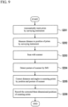
FIG. 9 . - First, in Step S201, the surveying
instrument 20 starts automatic tracking of theprism 9 of the surveying moving device 10'. - Next, in Step S202, the surveying
instrument 20 measures a distance and an angle to an automatically tracked position by thedistance measuring unit 20 to measure a three-dimensional position (absolute coordinates) of theprism 9. The surveyinginstrument 20 transmits the three-dimensional position of theprism 9 to the surveying moving device 10'. - Next, in Step S203, in parallel with Steps S201 and S202, the surveying moving device 10' performs a distance measurement and an angle measurement by the
scanner 3 to measure three-dimensional positions of scanning points. - Next, in Step S204, in parallel with Steps S201 to S203, the surveying moving device 10' detects a posture (a roll angle, a pitch angle, and a yaw angle) of the scanner from the
IMU 5. - Next, in Step S205, the
arithmetic control unit 7 of the surveying moving device 10' associates the positional information of theprism 9 obtained from the surveyinginstrument 20 in Step S202, the three-dimensional point group data of the scanning points obtained from thescanner 3 in Step S203, and the posture information of the scanner obtained from theIMU 5 in Step S204 with each other by time. Then, the scanningposition correcting unit 7A corrects the three-dimensional positions of the scanning points obtained in Step S203 by the position and posture of the scanner. - In detail, in Step S202, the position of the
prism 9 is precisely measured as absolute coordinates by the surveyinginstrument 20. In Step S204, an inclination (posture) of thescanner 3 is known. Therefore, the scanningposition correcting unit 7A corrects the reference optical axis O of the scanner to a posture direction of the scanner, and re-calculates a distance and an angle to each scanning point measured by thescanner 3 by setting coordinates moved by the respective deviations (dr, dp, dy) from the coordinates of theprism 9 as a measurement reference point 3o of the scanner. - Last, in Step S206, the measuring moving device 10' stores the three-dimensional positions (absolute coordinates) of the scanning points corrected in Step S205, and ends the operation.
- By using the survey system 1' of the present example, in addition to the effect obtained in the first example, a position of the scanner 3 (measurement reference point 3o of the scanner) can be accurately obtained with use of the surveying
instrument 20, so that accuracy of the three-dimensional point group data can be further improved. - Hereinafter, the same components as in the first or second example are designated by the same reference signs, and descriptions thereof are omitted. An entire configuration diagram of a
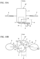
survey system 1" according to the embodiment is the same asFIG. 6 .FIGS. 10 are configuration diagrams of asurveying moving device 10" according to a embodiment, andFIG. 10A is a side view of the same device, andFIG. 10B is a bottom view of the same device.FIG. 11 is a control block diagram of thesurvey system 1". - As illustrated in
FIG. 10 , thesurvey system 1" includes the surveying movingdevice 10" and the surveyinginstrument 20. As illustrated inFIG. 10A and FIG. 10B , the surveying movingdevice 10" includes themobile body 2, thescanner 3, theprism 9, and acamera 13 in place of theIMU 5. Theprism 9 is fixed to a lateral side of a tip end of a lens portion of thescanner 3 as in the second example. Deviations (dr, dp, dy) in the roll axis direction, the pitch axis direction, and the yaw axis direction between the measurement reference point 3o of thescanner 3 and the optical center 9o of theprism 9 are made known in advance of attachment of theprism 9. - The
camera 13 is an image sensor such as a CCD sensor or a CMOS sensor, and a position of each pixel on an imaging element can be identified. For example, a position of each pixel on an image is identified by a coordinate system using an imaging optical axis O" of thecamera 13 as an origin. Thecamera 13 is incorporated in themobile body 2, and is fixed so as to be displaced from the mechanism of thescanner 3. The imaging optical axis O" of thecamera 13 is set so as to be positioned vertically downward when themobile body 2 is in a horizontal posture (refer toFIG. 10B ). In the present embodiment, thecamera 13 functions as a posture detecting device to detect a posture of thescanner 3. - A control system of the
survey system 1" includes, as illustrated inFIG. 11 , on thesurveying moving device 10" side, thescanner 3, thearithmetic control unit 7, theoperation unit 8, thecommunication unit 11, thetimer 12, and thecamera 13. Thearithmetic control unit 7 acquires three-dimensional point group data (distances and angles to scanning points) from thescanner 3, and acquires image data from thecamera 13. Thearithmetic control unit 7 acquires a system time from thetimer 12 at the timing of outputting a light transmission signal of thescanner 3, and provides the time to the three-dimensional point group data and the image data. The scanningposition correcting unit 7A corrects a three-dimensional position obtained by thescanner 3 by a position and posture of the scanner. This is described in detail below. A control system on the surveyinginstrument 20 is the same as in the second example. - Next, an operation flow of the
survey system 1" is described with reference toFIG. 12 . - First, in Step S301, the surveying
instrument 20 starts automatic tracking of theprism 9 of thesurveying moving device 10". - Next, in Step S302, the surveying
instrument 20 measures a distance and an angle to an automatically tracked position by thedistance measuring unit 29 to measure a three-dimensional position (absolute coordinates) of theprism 9. The surveyinginstrument 20 transmits the three-dimensional position of theprism 9 to thesurveying moving device 10". - Next, in Step S303, in parallel with Steps S301 and S302, the surveying moving
device 10" performs a distance measurement and an angle measurement by thescanner 3 to measure three-dimensional positions of scanning points. - Next, in Step S304, in parallel with Steps S301 to S303, the surveying moving
device 10" acquires image data by thecamera 13. Thearithmetic control unit 7 of thesurveying moving device 10" photographically analyzes the image data to detect a posture (a roll angle, a pitch angle, and a yaw angle) of thecamera 13. Thecamera 13 and thescanner 3 are integrated together, so that the posture of thecamera 13 can be regarded as a posture of thescanner 3. - Next, in Step S305, the
arithmetic control unit 7 associates the positional information of theprism 9 obtained from the surveyinginstrument 20 in Step S302, the three-dimensional point group data of scanning points obtained from thescanner 3 in Step S303, and the posture information of the scanner obtained through the photographic analysis in Step S304 with each other by time. Then, the scanningposition correcting unit 7A corrects the three-dimensional positions of the scanning points obtained in Step S303 by the position and posture of the scanner. - In detail, in Step S302, a position of the
prism 9 is precisely measured as absolute coordinates by the surveyinginstrument 20. In Step S304, an inclination (posture) of thescanner 3 is known. Therefore, the scanningposition correcting unit 7A corrects the reference optical axis O of the scanner to a posture direction of the scanner, and re-calculates a distance and an angle to each scanning point measured by thescanner 3 by setting coordinates moved by the deviations (dr, dp, dy) from the coordinates of theprism 9 as a measurement reference point 3o of the scanner. - Last, in Step S306, the surveying moving
device 10" stores the three-dimensional positions (absolute coordinates) of the scanning points corrected in Step S305, and ends the operation. - By using the
survey system 1" of the present embodiment, in addition to the effects of the first and second examples, due to the use of thecamera 13 for detection of a posture of thescanner 3, the system can be more inexpensively configured than in the case using a precision IMU. - Next, preferred modifications of the embodiments described above are shown.
- In the second example and the embodiment, the surveying moving
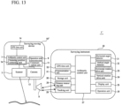
device 10', 10" and the surveyinginstrument 20 respectively include thetimer 12 and thetimer 32 for time synchronization, however, accurate time synchronization is preferably performed by the configuration described below. An example is shown by using the second example.FIG. 13 illustrates a modification of the survey system 1' according to the second example. - The surveying moving device 10' includes a
GPS time unit 14 in place of thetimer 12, and further includes a time synchronizing unit 15. The surveyinginstrument 20 includes aGPS time unit 33 in place of thetimer 32. - Each of the
GPS time unit 14 and theGPS time unit 33 includes a clock that receives a signal from a GPS satellite and generates a UTC and a PPS signal being a constant-frequency pulse. TheGPS time unit 14 provides a first time to the three-dimensional point group data and the posture information of the scanner at the timing of outputting a light transmission signal of thescanner 3. TheGPS time unit 33 provides a second time to the distance measurement and angle measurement values of theprism 9 at the timing of outputting a light transmission signal of thedistance measuring unit 29. - After all scanning by the
scanner 3 is finished, the time synchronizing unit 15 acquires the three-dimensional point group data given the first time from thearithmetic control unit 7, and acquires the distance measurement and angle measurement values of theprism 9 given the second time via thecommunication unit 11. When a survey period of the surveyinginstrument 20 is shorter (higher in frequency) than a scanning period of thescanner 3, the time synchronizing unit 15 extracts distance measurement and angle measurement values and three-dimensional point group data which are provided with a first time and a second time, respectively, matching each other, and associates the extracted distance measurement and angle measurement values of theprism 9 and the extracted three-dimensional point group data with each other. When there are no distance measurement and angle measurement values and three-dimensional point group data with a first time and a second time matching each other, a second time just before a certain first time and a second time just after the certain first time are extracted, and distance measurement and angle measurement values at a second time are calculated by interpolation. The above-described time synchronization can also be applied in a case where the survey period is longer (lower in frequency) than the scanning period. - In the second example or the embodiment, the
mobile bodies 2 of thesurveying moving device 10', 10" is a UAV, however, themobile body 2 is only required to be movable in a survey site. An example is shown by using the second example.FIG. 14 illustrates another modification of the survey system 1' according to the second example. A mobile body 2' illustrated inFIG. 14 is a vehicle, and on the roof of the vehicle, a unit in which thescanner 3, theIMU 5, and theprism 9 are integrated is mounted. Amobile body 2" illustrated inFIG. 14 is a handheld housing, and to this housing, a unit in which thescanner 3, theIMU 5, and theprism 9 are integrated is attached. Even when the mobile body has this form, an effect equivalent to that of the second example is obtained. - In the first or second example, the surveying moving
device 10, 10' may include, as its arbitrary element, acamera 13 to color three-dimensional point group data acquired by thescanner 3. In the embodiment, thecamera 13 is provided for posture detection of the scanner, however, it may also be used to color three-dimensional point group data. - In the embodiment including the
camera 13, thescanner 3 can perform two-dimensional circular scanning as illustrated inFIG. 5A by freely deflecting the distance measuring light 3h', so that scanning according to an angle of view of thecamera 13 is possible. A scanning range can be made to correspond to an image range of thecamera 13, so that there is no waste in the scanning range, and a point group density of three-dimensional point group data in an image taken by thecamera 13 can be increased. - In the first to third examples, the scanning
position correcting unit 7A that corrects three-dimensional positions of scanning points by a position and a posture of the scanner is provided in thearithmetic control unit 7 of the surveying moving device, however, it may be provided in an information processing terminal (personal computer or the like). - In Step S202 of the second example and Step S302 of the embodiment, the surveying
instrument 20 transmits the three-dimensional position of theprism 9 to thesurveying moving device 10, however, it may transmit the three-dimensional position to a separate recording device. In addition, it is also possible that three-dimensional position group data of scanning points and posture information are also transmitted to a separate recording device and that each data is acquired by an information processing terminal and is corrected another day. - While embodiments and modifications of a preferred survey system of the present invention are described above, the respective embodiments and modifications can be combined based on knowledge of a person skilled in the art, and such combination modes are also included in the scope of the present invention.
-
- 1, 1', 1" Survey system
- 2 Mobile body
- 3 Scanner
- 3a Emitting unit
- 3b Light receiving unit
- 3c Distance measuring unit
- 3f, 3g Risley prism (first optical axis deflecting unit)
- 3h Optical axis of distance measuring light
- 3h' Distance measuring light
- 3j, 3k Fresnel prism (second optical axis deflecting unit)
- 3l Light receiving optical axis of reflected distance measuring light
- 3l' Reflected distance measuring light
- 3m Emitting direction detecting unit
- 4 GPS device (position measuring device)
- 5 Inertial measurement unit (posture detecting device)
- 9 Prism
- 10, 10', 10" Surveying moving device
- 13 Camera (posture detecting device)
- 20 Surveying instrument (position measuring device)
- 28 Tracking unit
Claims (1)
- A survey system (1") comprising a surveying moving device (10") and a surveying instrument (20), scanning three-dimensional point group data by work together the surveying moving device and the surveying instrument, characterized in that
the surveying moving device (10") includes:a mobile body (2);a scanner (3) including an emitting unit (3a) configured to emit a distance measuring light, a light receiving unit (3b) configured to receive a reflected distance measuring light, a distance measuring unit (3c) configured to perform a distance measurement based on an output of the light receiving unit (3b), a first optical axis deflecting unit disposed on an optical axis of the distance measuring light and configured to deflect the distance measuring light, a second optical axis deflecting unit disposed on a light receiving optical axis of the reflected distance measuring light and configured to deflect the reflected distance measuring light at the same angle in the same direction as those of the first optical axis deflecting unit, and an emitting direction detecting unit configured to detect a deflection angle and a direction of the first optical axis deflecting unit and the second optical axis deflecting unit;a camera (13);a prism (9);a timer (12) that provides time to three-dimensional point group data of the scanner and image data of the camera;an arithmetic control unit (7);a communication unit (11); andan operation unit (8),the prism (9) is fixed to a lateral side of a tip end of a lens portion of the scanner (3),the camera (13) is an image sensor, and a position of each pixel on an imaging element can be identified,the camera (13) is incorporated in the mobile body(2), and is fixed so as to be displaced from the mechanism of the scanner(3),and the imaging optical axis (O") of the camera(13) is set so as to be positioned vertically downward when the mobile body(2) is in a horizontal posture,in the mobile body (2), deviations (dr, dp, dy) in a roll axis direction, a pitch axis direction, and a yaw axis direction between a measurement reference point (3o) of the scanner (3) and an optical center (9o) of the prism (9) are made known in advance, andthe camera (13) is a posture detecting device configured to measure a posture of the scanner (3), the surveying instrument (20) includes a tracking unit (28) that performs automatic tracking to the prism (9) that becomes a target of the surveying instrument (20);a surveying-instrument-side distance measuring unit (29) that measures a distance and an angle to the prism (9);a surveying-instrument-side timer (32) that provides time to measurement values of the distance and the angle; anda surveying-instrument-side communication unit (31), the surveying instrument (20) functions as a position measuring device configured to measure a position of the scanner (3), the arithmetic control unit (7) acquires three-dimensional point group data from the scanner (3), and acquires image data from the camera (13), and the arithmetic control unit (7) acquires a system time from the timer (12) at the timing of outputting a light transmission signal of the scanner (3), and provides the time to the three-dimensional point group data and the image data, and the scanning position correcting unit (7A) corrects a three-dimensional position obtained by the scanner (3) by a position and posture of the scanner,the surveying instrument (20) tracks the prism (9) by the tracking unit (28), measures a three-dimensional position of the prism (9) by the surveying-instrument-side distance measuring unit (29), and transmits the three-dimensional position of the prism (9) to the surveying moving device (10"),the surveying moving device (10") performs a distance measurement and an angle measurement by the scanner (3) to measure three-dimensional positions of scanning points, and the scanning position correcting unit (7A)correcting the three-dimensional position obtained by the scanner (3) by a position and posture of the scanner (3), photographically analyzes image data acquired by the camera (13), and detects a posture information of the camera (13),the arithmetic control unit (7) associates the three-dimensional position of the prism (9), the three-dimensional positions of point group data of scanning points, and the posture information of the scanner with each other by time,the surveying moving device (10") regards a posture of the camera (13), matches a posture of the scanner (3) because the camera and the scanner are fixed to the moving body therefore integrated together, andthe surveying moving device (10") corrects a reference optical axis (O) of the scanner to a posture direction of the scanner, and re-calculates a distance and an angle each of the scanning points by setting coordinates moved by the deviations (dr, dp, dy) from the coordinates of the prism (9) as the measurement reference point (3o) of the scanner.
Applications Claiming Priority (1)
| Application Number | Priority Date | Filing Date | Title |
|---|---|---|---|
| JP2017179701A JP6994879B2 (en) | 2017-09-20 | 2017-09-20 | Surveying system |
Publications (2)
| Publication Number | Publication Date |
|---|---|
| EP3460396A1 EP3460396A1 (en) | 2019-03-27 |
| EP3460396B1 true EP3460396B1 (en) | 2024-10-23 |
Family
ID=63579011
Family Applications (1)
| Application Number | Title | Priority Date | Filing Date |
|---|---|---|---|
| EP18193950.5A Active EP3460396B1 (en) | 2017-09-20 | 2018-09-12 | Survey system |
Country Status (3)
| Country | Link |
|---|---|
| US (1) | US11460299B2 (en) |
| EP (1) | EP3460396B1 (en) |
| JP (1) | JP6994879B2 (en) |
Families Citing this family (12)
| Publication number | Priority date | Publication date | Assignee | Title |
|---|---|---|---|---|
| JP7017422B2 (en) * | 2018-01-31 | 2022-02-08 | 株式会社トプコン | Surveying device |
| JP7161298B2 (en) * | 2018-03-26 | 2022-10-26 | 株式会社トプコン | target device, surveying system |
| JP2020203664A (en) * | 2019-03-29 | 2020-12-24 | 株式会社トプコン | Flight control system for unmanned aerial vehicle and topography measuring system |
| JP7491730B2 (en) * | 2020-04-30 | 2024-05-28 | 株式会社トプコン | Work management system, work management method, and work management program therefor |
| JP2022087978A (en) * | 2020-12-02 | 2022-06-14 | 三菱電機株式会社 | Position / posture calculation device, position / posture calculation method and surveying device |
| JP2022089308A (en) * | 2020-12-04 | 2022-06-16 | 株式会社豊田自動織機 | Autonomous driving system |
| JP2022120895A (en) * | 2021-02-08 | 2022-08-19 | 株式会社トプコン | Three-dimensional position measurement system, measurement method, and measurement marker |
| JP7731230B2 (en) * | 2021-07-14 | 2025-08-29 | 株式会社トプコン | Information projection system and information projection method |
| JP2023050516A (en) * | 2021-09-30 | 2023-04-11 | 株式会社トプコン | Hammering inspection system |
| EP4311999B1 (en) | 2022-07-29 | 2026-01-21 | Leica Geosystems AG | Automatic, reference-free precise stationing of a geodetic survey instrument based on environment information |
| EP4312000B1 (en) | 2022-07-29 | 2025-11-05 | Leica Geosystems AG | Automatic, stationing of a geodetic survey instrument based on reference marker database |
| JP7143001B1 (en) * | 2022-08-02 | 2022-09-28 | 株式会社マプリィ | Measuring system and measuring method |
Family Cites Families (12)
| Publication number | Priority date | Publication date | Assignee | Title |
|---|---|---|---|---|
| JP5145013B2 (en) * | 2007-11-01 | 2013-02-13 | 株式会社トプコン | Surveying instrument |
| EP2511656A1 (en) * | 2011-04-14 | 2012-10-17 | Hexagon Technology Center GmbH | Measuring system for determining the 3D coordinates of an object surface |
| JP5122693B1 (en) * | 2012-05-18 | 2013-01-16 | エー・シー・エス株式会社 | In-vehicle survey system |
| US20150254861A1 (en) * | 2012-10-18 | 2015-09-10 | T. Eric Chornenky | Apparatus and method for determining spatial information about environment |
| JP5561843B1 (en) | 2013-01-07 | 2014-07-30 | 株式会社amuse oneself | Control device, surveying system, program, recording medium, and measuring method |
| US9201424B1 (en) * | 2013-08-27 | 2015-12-01 | Google Inc. | Camera calibration using structure from motion techniques |
| JP6326237B2 (en) * | 2014-01-31 | 2018-05-16 | 株式会社トプコン | Measuring system |
| JP6541365B2 (en) * | 2015-02-16 | 2019-07-10 | 株式会社トプコン | Posture detection device and data acquisition device |
| JP6616077B2 (en) | 2015-02-16 | 2019-12-04 | 株式会社トプコン | Measuring device and 3D camera |
| JP6594686B2 (en) | 2015-07-14 | 2019-10-23 | 東急建設株式会社 | Three-dimensional shape measuring apparatus, three-dimensional shape measuring method, and program |
| EP3165945B1 (en) | 2015-11-03 | 2024-01-03 | Leica Geosystems AG | Surface measuring device for determining the 3d coordinates of a surface |
| JP6691721B2 (en) * | 2016-02-15 | 2020-05-13 | 株式会社トプコン | Flight planning method and flight guidance system |
-
2017
- 2017-09-20 JP JP2017179701A patent/JP6994879B2/en active Active
-
2018
- 2018-09-05 US US16/122,028 patent/US11460299B2/en active Active
- 2018-09-12 EP EP18193950.5A patent/EP3460396B1/en active Active
Also Published As
| Publication number | Publication date |
|---|---|
| US11460299B2 (en) | 2022-10-04 |
| EP3460396A1 (en) | 2019-03-27 |
| JP2019056571A (en) | 2019-04-11 |
| US20190086206A1 (en) | 2019-03-21 |
| JP6994879B2 (en) | 2022-02-04 |
Similar Documents
| Publication | Publication Date | Title |
|---|---|---|
| EP3460396B1 (en) | Survey system | |
| US11333764B2 (en) | Survey system | |
| US10324183B2 (en) | UAV measuring apparatus and UAV measuring system | |
| JP5688876B2 (en) | Calibration method for laser scanner measurement system | |
| US9958268B2 (en) | Three-dimensional measuring method and surveying system | |
| EP3205977B1 (en) | Flight plan preparing method and flying vehicle guiding system | |
| US9758239B2 (en) | System and method for controlling an unmanned air vehicle | |
| CA2832956C (en) | System and method for controlling an unmanned aerial vehicle | |
| US10636171B2 (en) | Device, method, and system for tracking unmanned aerial vehicle, and program therefor | |
| US11614546B2 (en) | Methods for geospatial positioning and portable positioning devices thereof | |
| JP2019132769A5 (en) | ||
| US10527423B1 (en) | Fusion of vision and depth sensors for navigation in complex environments | |
| US20210229810A1 (en) | Information processing device, flight control method, and flight control system | |
| US10146230B2 (en) | Control device, optical device, and control method for tracking unmanned aerial vehicle, and system and program therefor | |
| JP7011908B2 (en) | Optical information processing equipment, optical information processing method and optical information processing program | |
| US12524870B2 (en) | Bar arrangement inspection system and bar arrangement inspection method | |
| US20220099442A1 (en) | Surveying System | |
| JP7161298B2 (en) | target device, surveying system | |
| JP2018146524A (en) | Survey system | |
| JP7203935B2 (en) | Optical information processing device, optical information processing method, and optical information processing program | |
| JP2022147973A (en) | Attitude detection device and attitude control system of flying object | |
| JP2023048409A (en) | surveying system | |
| JP6954830B2 (en) | Target device, surveying method, surveying device and surveying program |
Legal Events
| Date | Code | Title | Description |
|---|---|---|---|
| PUAI | Public reference made under article 153(3) epc to a published international application that has entered the european phase |
Free format text: ORIGINAL CODE: 0009012 |
|
| STAA | Information on the status of an ep patent application or granted ep patent |
Free format text: STATUS: THE APPLICATION HAS BEEN PUBLISHED |
|
| AK | Designated contracting states |
Kind code of ref document: A1 Designated state(s): AL AT BE BG CH CY CZ DE DK EE ES FI FR GB GR HR HU IE IS IT LI LT LU LV MC MK MT NL NO PL PT RO RS SE SI SK SM TR |
|
| AX | Request for extension of the european patent |
Extension state: BA ME |
|
| STAA | Information on the status of an ep patent application or granted ep patent |
Free format text: STATUS: REQUEST FOR EXAMINATION WAS MADE |
|
| 17P | Request for examination filed |
Effective date: 20190902 |
|
| RBV | Designated contracting states (corrected) |
Designated state(s): AL AT BE BG CH CY CZ DE DK EE ES FI FR GB GR HR HU IE IS IT LI LT LU LV MC MK MT NL NO PL PT RO RS SE SI SK SM TR |
|
| STAA | Information on the status of an ep patent application or granted ep patent |
Free format text: STATUS: EXAMINATION IS IN PROGRESS |
|
| 17Q | First examination report despatched |
Effective date: 20210728 |
|
| GRAP | Despatch of communication of intention to grant a patent |
Free format text: ORIGINAL CODE: EPIDOSNIGR1 |
|
| STAA | Information on the status of an ep patent application or granted ep patent |
Free format text: STATUS: GRANT OF PATENT IS INTENDED |
|
| INTG | Intention to grant announced |
Effective date: 20240605 |
|
| GRAS | Grant fee paid |
Free format text: ORIGINAL CODE: EPIDOSNIGR3 |
|
| GRAA | (expected) grant |
Free format text: ORIGINAL CODE: 0009210 |
|
| STAA | Information on the status of an ep patent application or granted ep patent |
Free format text: STATUS: THE PATENT HAS BEEN GRANTED |
|
| AK | Designated contracting states |
Kind code of ref document: B1 Designated state(s): AL AT BE BG CH CY CZ DE DK EE ES FI FR GB GR HR HU IE IS IT LI LT LU LV MC MK MT NL NO PL PT RO RS SE SI SK SM TR |
|
| REG | Reference to a national code |
Ref country code: GB Ref legal event code: FG4D |
|
| REG | Reference to a national code |
Ref country code: CH Ref legal event code: EP |
|
| REG | Reference to a national code |
Ref country code: DE Ref legal event code: R096 Ref document number: 602018075682 Country of ref document: DE |
|
| REG | Reference to a national code |
Ref country code: IE Ref legal event code: FG4D |
|
| REG | Reference to a national code |
Ref country code: LT Ref legal event code: MG9D |
|
| REG | Reference to a national code |
Ref country code: NL Ref legal event code: MP Effective date: 20241023 |
|
| REG | Reference to a national code |
Ref country code: AT Ref legal event code: MK05 Ref document number: 1735183 Country of ref document: AT Kind code of ref document: T Effective date: 20241023 |
|
| PG25 | Lapsed in a contracting state [announced via postgrant information from national office to epo] |
Ref country code: NL Free format text: LAPSE BECAUSE OF FAILURE TO SUBMIT A TRANSLATION OF THE DESCRIPTION OR TO PAY THE FEE WITHIN THE PRESCRIBED TIME-LIMIT Effective date: 20241023 |
|
| PG25 | Lapsed in a contracting state [announced via postgrant information from national office to epo] |
Ref country code: NL Free format text: LAPSE BECAUSE OF FAILURE TO SUBMIT A TRANSLATION OF THE DESCRIPTION OR TO PAY THE FEE WITHIN THE PRESCRIBED TIME-LIMIT Effective date: 20241023 |
|
| PG25 | Lapsed in a contracting state [announced via postgrant information from national office to epo] |
Ref country code: PT Free format text: LAPSE BECAUSE OF FAILURE TO SUBMIT A TRANSLATION OF THE DESCRIPTION OR TO PAY THE FEE WITHIN THE PRESCRIBED TIME-LIMIT Effective date: 20250224 Ref country code: HR Free format text: LAPSE BECAUSE OF FAILURE TO SUBMIT A TRANSLATION OF THE DESCRIPTION OR TO PAY THE FEE WITHIN THE PRESCRIBED TIME-LIMIT Effective date: 20241023 Ref country code: IS Free format text: LAPSE BECAUSE OF FAILURE TO SUBMIT A TRANSLATION OF THE DESCRIPTION OR TO PAY THE FEE WITHIN THE PRESCRIBED TIME-LIMIT Effective date: 20250223 |
|
| PG25 | Lapsed in a contracting state [announced via postgrant information from national office to epo] |
Ref country code: FI Free format text: LAPSE BECAUSE OF FAILURE TO SUBMIT A TRANSLATION OF THE DESCRIPTION OR TO PAY THE FEE WITHIN THE PRESCRIBED TIME-LIMIT Effective date: 20241023 |
|
| PG25 | Lapsed in a contracting state [announced via postgrant information from national office to epo] |
Ref country code: BG Free format text: LAPSE BECAUSE OF FAILURE TO SUBMIT A TRANSLATION OF THE DESCRIPTION OR TO PAY THE FEE WITHIN THE PRESCRIBED TIME-LIMIT Effective date: 20241023 |
|
| PG25 | Lapsed in a contracting state [announced via postgrant information from national office to epo] |
Ref country code: ES Free format text: LAPSE BECAUSE OF FAILURE TO SUBMIT A TRANSLATION OF THE DESCRIPTION OR TO PAY THE FEE WITHIN THE PRESCRIBED TIME-LIMIT Effective date: 20241023 |
|
| PG25 | Lapsed in a contracting state [announced via postgrant information from national office to epo] |
Ref country code: NO Free format text: LAPSE BECAUSE OF FAILURE TO SUBMIT A TRANSLATION OF THE DESCRIPTION OR TO PAY THE FEE WITHIN THE PRESCRIBED TIME-LIMIT Effective date: 20250123 |
|
| PG25 | Lapsed in a contracting state [announced via postgrant information from national office to epo] |
Ref country code: GR Free format text: LAPSE BECAUSE OF FAILURE TO SUBMIT A TRANSLATION OF THE DESCRIPTION OR TO PAY THE FEE WITHIN THE PRESCRIBED TIME-LIMIT Effective date: 20250124 Ref country code: AT Free format text: LAPSE BECAUSE OF FAILURE TO SUBMIT A TRANSLATION OF THE DESCRIPTION OR TO PAY THE FEE WITHIN THE PRESCRIBED TIME-LIMIT Effective date: 20241023 Ref country code: LV Free format text: LAPSE BECAUSE OF FAILURE TO SUBMIT A TRANSLATION OF THE DESCRIPTION OR TO PAY THE FEE WITHIN THE PRESCRIBED TIME-LIMIT Effective date: 20241023 |
|
| PG25 | Lapsed in a contracting state [announced via postgrant information from national office to epo] |
Ref country code: PL Free format text: LAPSE BECAUSE OF FAILURE TO SUBMIT A TRANSLATION OF THE DESCRIPTION OR TO PAY THE FEE WITHIN THE PRESCRIBED TIME-LIMIT Effective date: 20241023 |
|
| PG25 | Lapsed in a contracting state [announced via postgrant information from national office to epo] |
Ref country code: RS Free format text: LAPSE BECAUSE OF FAILURE TO SUBMIT A TRANSLATION OF THE DESCRIPTION OR TO PAY THE FEE WITHIN THE PRESCRIBED TIME-LIMIT Effective date: 20250123 |
|
| PG25 | Lapsed in a contracting state [announced via postgrant information from national office to epo] |
Ref country code: SM Free format text: LAPSE BECAUSE OF FAILURE TO SUBMIT A TRANSLATION OF THE DESCRIPTION OR TO PAY THE FEE WITHIN THE PRESCRIBED TIME-LIMIT Effective date: 20241023 |
|
| PG25 | Lapsed in a contracting state [announced via postgrant information from national office to epo] |
Ref country code: DK Free format text: LAPSE BECAUSE OF FAILURE TO SUBMIT A TRANSLATION OF THE DESCRIPTION OR TO PAY THE FEE WITHIN THE PRESCRIBED TIME-LIMIT Effective date: 20241023 |
|
| PG25 | Lapsed in a contracting state [announced via postgrant information from national office to epo] |
Ref country code: EE Free format text: LAPSE BECAUSE OF FAILURE TO SUBMIT A TRANSLATION OF THE DESCRIPTION OR TO PAY THE FEE WITHIN THE PRESCRIBED TIME-LIMIT Effective date: 20241023 |
|
| PG25 | Lapsed in a contracting state [announced via postgrant information from national office to epo] |
Ref country code: RO Free format text: LAPSE BECAUSE OF FAILURE TO SUBMIT A TRANSLATION OF THE DESCRIPTION OR TO PAY THE FEE WITHIN THE PRESCRIBED TIME-LIMIT Effective date: 20241023 |
|
| REG | Reference to a national code |
Ref country code: DE Ref legal event code: R097 Ref document number: 602018075682 Country of ref document: DE |
|
| PG25 | Lapsed in a contracting state [announced via postgrant information from national office to epo] |
Ref country code: SK Free format text: LAPSE BECAUSE OF FAILURE TO SUBMIT A TRANSLATION OF THE DESCRIPTION OR TO PAY THE FEE WITHIN THE PRESCRIBED TIME-LIMIT Effective date: 20241023 |
|
| PG25 | Lapsed in a contracting state [announced via postgrant information from national office to epo] |
Ref country code: CZ Free format text: LAPSE BECAUSE OF FAILURE TO SUBMIT A TRANSLATION OF THE DESCRIPTION OR TO PAY THE FEE WITHIN THE PRESCRIBED TIME-LIMIT Effective date: 20241023 |
|
| PG25 | Lapsed in a contracting state [announced via postgrant information from national office to epo] |
Ref country code: IT Free format text: LAPSE BECAUSE OF FAILURE TO SUBMIT A TRANSLATION OF THE DESCRIPTION OR TO PAY THE FEE WITHIN THE PRESCRIBED TIME-LIMIT Effective date: 20241023 |
|
| PLBE | No opposition filed within time limit |
Free format text: ORIGINAL CODE: 0009261 |
|
| STAA | Information on the status of an ep patent application or granted ep patent |
Free format text: STATUS: NO OPPOSITION FILED WITHIN TIME LIMIT |
|
| PG25 | Lapsed in a contracting state [announced via postgrant information from national office to epo] |
Ref country code: SE Free format text: LAPSE BECAUSE OF FAILURE TO SUBMIT A TRANSLATION OF THE DESCRIPTION OR TO PAY THE FEE WITHIN THE PRESCRIBED TIME-LIMIT Effective date: 20241023 |
|
| 26N | No opposition filed |
Effective date: 20250724 |
|
| REG | Reference to a national code |
Ref country code: CH Ref legal event code: U11 Free format text: ST27 STATUS EVENT CODE: U-0-0-U10-U11 (AS PROVIDED BY THE NATIONAL OFFICE) Effective date: 20251001 |
|
| PGFP | Annual fee paid to national office [announced via postgrant information from national office to epo] |
Ref country code: DE Payment date: 20250730 Year of fee payment: 8 |
|
| PGFP | Annual fee paid to national office [announced via postgrant information from national office to epo] |
Ref country code: CH Payment date: 20251001 Year of fee payment: 8 |