EP3460244B1 - Compressor unit - Google Patents
Compressor unit Download PDFInfo
- Publication number
- EP3460244B1 EP3460244B1 EP16902399.1A EP16902399A EP3460244B1 EP 3460244 B1 EP3460244 B1 EP 3460244B1 EP 16902399 A EP16902399 A EP 16902399A EP 3460244 B1 EP3460244 B1 EP 3460244B1
- Authority
- EP
- European Patent Office
- Prior art keywords
- compressor
- injection
- muffler
- connecting part
- injection pipe
- Prior art date
- Legal status (The legal status is an assumption and is not a legal conclusion. Google has not performed a legal analysis and makes no representation as to the accuracy of the status listed.)
- Active
Links
Images


Classifications
-
- F—MECHANICAL ENGINEERING; LIGHTING; HEATING; WEAPONS; BLASTING
- F04—POSITIVE - DISPLACEMENT MACHINES FOR LIQUIDS; PUMPS FOR LIQUIDS OR ELASTIC FLUIDS
- F04C—ROTARY-PISTON, OR OSCILLATING-PISTON, POSITIVE-DISPLACEMENT MACHINES FOR LIQUIDS; ROTARY-PISTON, OR OSCILLATING-PISTON, POSITIVE-DISPLACEMENT PUMPS
- F04C18/00—Rotary-piston pumps specially adapted for elastic fluids
- F04C18/02—Rotary-piston pumps specially adapted for elastic fluids of arcuate-engagement type, i.e. with circular translatory movement of co-operating members, each member having the same number of teeth or tooth-equivalents
- F04C18/0207—Rotary-piston pumps specially adapted for elastic fluids of arcuate-engagement type, i.e. with circular translatory movement of co-operating members, each member having the same number of teeth or tooth-equivalents both members having co-operating elements in spiral form
- F04C18/0215—Rotary-piston pumps specially adapted for elastic fluids of arcuate-engagement type, i.e. with circular translatory movement of co-operating members, each member having the same number of teeth or tooth-equivalents both members having co-operating elements in spiral form where only one member is moving
-
- F—MECHANICAL ENGINEERING; LIGHTING; HEATING; WEAPONS; BLASTING
- F04—POSITIVE - DISPLACEMENT MACHINES FOR LIQUIDS; PUMPS FOR LIQUIDS OR ELASTIC FLUIDS
- F04C—ROTARY-PISTON, OR OSCILLATING-PISTON, POSITIVE-DISPLACEMENT MACHINES FOR LIQUIDS; ROTARY-PISTON, OR OSCILLATING-PISTON, POSITIVE-DISPLACEMENT PUMPS
- F04C29/00—Component parts, details or accessories of pumps or pumping installations, not provided for in groups F04C18/00 - F04C28/00
- F04C29/06—Silencing
- F04C29/065—Noise dampening volumes, e.g. muffler chambers
-
- F—MECHANICAL ENGINEERING; LIGHTING; HEATING; WEAPONS; BLASTING
- F25—REFRIGERATION OR COOLING; COMBINED HEATING AND REFRIGERATION SYSTEMS; HEAT PUMP SYSTEMS; MANUFACTURE OR STORAGE OF ICE; LIQUEFACTION SOLIDIFICATION OF GASES
- F25B—REFRIGERATION MACHINES, PLANTS OR SYSTEMS; COMBINED HEATING AND REFRIGERATION SYSTEMS; HEAT PUMP SYSTEMS
- F25B31/00—Compressor arrangements
-
- F—MECHANICAL ENGINEERING; LIGHTING; HEATING; WEAPONS; BLASTING
- F04—POSITIVE - DISPLACEMENT MACHINES FOR LIQUIDS; PUMPS FOR LIQUIDS OR ELASTIC FLUIDS
- F04C—ROTARY-PISTON, OR OSCILLATING-PISTON, POSITIVE-DISPLACEMENT MACHINES FOR LIQUIDS; ROTARY-PISTON, OR OSCILLATING-PISTON, POSITIVE-DISPLACEMENT PUMPS
- F04C2210/00—Fluid
- F04C2210/10—Fluid working
- F04C2210/1027—CO2
-
- F—MECHANICAL ENGINEERING; LIGHTING; HEATING; WEAPONS; BLASTING
- F04—POSITIVE - DISPLACEMENT MACHINES FOR LIQUIDS; PUMPS FOR LIQUIDS OR ELASTIC FLUIDS
- F04C—ROTARY-PISTON, OR OSCILLATING-PISTON, POSITIVE-DISPLACEMENT MACHINES FOR LIQUIDS; ROTARY-PISTON, OR OSCILLATING-PISTON, POSITIVE-DISPLACEMENT PUMPS
- F04C2230/00—Manufacture
- F04C2230/20—Manufacture essentially without removing material
- F04C2230/23—Manufacture essentially without removing material by permanently joining parts together
- F04C2230/231—Manufacture essentially without removing material by permanently joining parts together by welding
-
- F—MECHANICAL ENGINEERING; LIGHTING; HEATING; WEAPONS; BLASTING
- F04—POSITIVE - DISPLACEMENT MACHINES FOR LIQUIDS; PUMPS FOR LIQUIDS OR ELASTIC FLUIDS
- F04C—ROTARY-PISTON, OR OSCILLATING-PISTON, POSITIVE-DISPLACEMENT MACHINES FOR LIQUIDS; ROTARY-PISTON, OR OSCILLATING-PISTON, POSITIVE-DISPLACEMENT PUMPS
- F04C2240/00—Components
- F04C2240/80—Other components
- F04C2240/805—Fastening means, e.g. bolts
-
- F—MECHANICAL ENGINEERING; LIGHTING; HEATING; WEAPONS; BLASTING
- F04—POSITIVE - DISPLACEMENT MACHINES FOR LIQUIDS; PUMPS FOR LIQUIDS OR ELASTIC FLUIDS
- F04C—ROTARY-PISTON, OR OSCILLATING-PISTON, POSITIVE-DISPLACEMENT MACHINES FOR LIQUIDS; ROTARY-PISTON, OR OSCILLATING-PISTON, POSITIVE-DISPLACEMENT PUMPS
- F04C2240/00—Components
- F04C2240/80—Other components
- F04C2240/806—Pipes for fluids; Fittings therefor
-
- F—MECHANICAL ENGINEERING; LIGHTING; HEATING; WEAPONS; BLASTING
- F04—POSITIVE - DISPLACEMENT MACHINES FOR LIQUIDS; PUMPS FOR LIQUIDS OR ELASTIC FLUIDS
- F04C—ROTARY-PISTON, OR OSCILLATING-PISTON, POSITIVE-DISPLACEMENT MACHINES FOR LIQUIDS; ROTARY-PISTON, OR OSCILLATING-PISTON, POSITIVE-DISPLACEMENT PUMPS
- F04C29/00—Component parts, details or accessories of pumps or pumping installations, not provided for in groups F04C18/00 - F04C28/00
- F04C29/0007—Injection of a fluid in the working chamber for sealing, cooling and lubricating
-
- F—MECHANICAL ENGINEERING; LIGHTING; HEATING; WEAPONS; BLASTING
- F04—POSITIVE - DISPLACEMENT MACHINES FOR LIQUIDS; PUMPS FOR LIQUIDS OR ELASTIC FLUIDS
- F04C—ROTARY-PISTON, OR OSCILLATING-PISTON, POSITIVE-DISPLACEMENT MACHINES FOR LIQUIDS; ROTARY-PISTON, OR OSCILLATING-PISTON, POSITIVE-DISPLACEMENT PUMPS
- F04C29/00—Component parts, details or accessories of pumps or pumping installations, not provided for in groups F04C18/00 - F04C28/00
- F04C29/06—Silencing
Definitions
- the present invention relates to a compressor unit installed in, among others, a refrigerating apparatus, an air-conditioning apparatus and a hot water supplier.
- a conventional refrigerating apparatus, air-conditioning apparatus or hot water supplier includes a compressor compressing refrigerant, a condenser rejecting heat from the compressed refrigerant, an expansion valve decreasing pressure of the refrigerant whose heat has been released and changing the refrigerant from liquid to gas, and an evaporator applying heat to adjust a refrigerant temperature to a target compressor suction temperature.
- Some compressors are equipped with an injection mechanism, in which a pipe is provided to permit a part of refrigerant flowing out of a condenser toward an evaporator to branch off and return to the compressor in a refrigerant circuit of an air-conditioning apparatus or other apparatuses. In the present description, this pipe is referred to as an injection pipe.
- the injection pipe is connected to an LEV (electronic linear expansion valve) of the refrigerant circuit.
- LEV electro linear expansion valve
- Patent Literature 1 discloses an injection pipe having an oil separating function disposed between an LEV and a compressor of an
- Patent Literature 1 When the amount of refrigerant in the injection pipe injected into the compressor is large or when an injection mechanism is not operative, the refrigerant may flow back from the compressor, and this generates pulsations in the injection pipe.
- the injection pipe disclosed in Patent Literature 1 is provided with a muffler at an end closer to the compressor to prevent damage or breakage of the injection pipe due to pulsations caused by flow-back of the refrigerant.
- Patent Literature 2 describes a screw compressor which includes an economizer circuit configured to eject intermediate pressure refrigerant into a compression chamber in the course of compression.
- the muffler disclosed in Patent Literature 1 has an inner diameter twice as large as an inner diameter of the injection pipe and has a length ten times as large as the inner diameter of the injection pipe. For this reason, it is difficult to stably fix the muffler to the injection pipe, causing a drawback in that the muffler is installed with weak installation strength. With insufficient installation strength, the muffler is unable to prevent pulsations generated in the injection pipe, resulting in a problem that damage or breakage of the injection pipe cannot be surely prevented.
- the present invention has been made to solve the above problem, and aims to prevent pulsations generated in the injection muffler and thereby to prevent damage or breakage of the injection pipe.
- the compressor unit of an embodiment of the present invention includes the features of claim 1.
- the compressor unit comprises a compressor, a condenser, and an injection pipe constituting a part of a refrigerant pipe connecting the compressor and the condenser, the injection pipe permitting a part of refrigerant flowing out of the condenser to branch off and flow into the compressor
- the injection pipe includes: a compressor connecting part connected to the compressor; an expansion valve connecting part connected to an expansion valve disposed in the injection pipe; and an injection muffler disposed between the compressor connecting part and the expansion valve connecting part, wherein the injection muffler has an inner diameter larger than an inner diameter of the compressor connecting part and an inner diameter of the expansion valve connecting part, and the injection muffler is fixed to a side of the compressor.
- the injection muffler has an inner diameter larger than an inner diameter of the compressor connecting part and an inner diameter of the expansion valve connecting part of the injection pipe, and the injection muffler is fixed to a side of the compressor. This allows more effective prevention of pulsations caused by flow-back of the refrigerant, which in turn allows prevention of damage or breakage of the injection pipe.
- a closed scroll compressor is taken as an example.
- the compressor is a component of a refrigeration cycle of an apparatus such as a refrigerator, a freezer, an automatic vending machine, an air-conditioning apparatus, a refrigerating device and a hot water supplier.
- size relationships among components may be different from actual ones.
- Fig. 1 is a schematic block diagram of a refrigeration cycle of an air-conditioning apparatus of Embodiment 1 of the present invention.
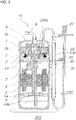
- Fig. 2 is a schematic diagram of a cross section of a compressor unit of Embodiment 1 of the present invention.
- the air-conditioning device 100 includes a compressor 21, a condenser 22, an expansion valve 23, an evaporator 24, an injection pipe 25, and an LEV 27.
- the compressor 21 sucks gas refrigerant and compresses it into a high-temperature and high-pressure state before discharging it to a refrigerant circuit.
- the compressor is a closed scroll compressor.
- the high-temperature and high-pressure gas refrigerant discharged from the compressor 21 flows into the condenser 22.
- the high-temperature and high-pressure gas refrigerant having flowed into the condenser 22 exchanges heat with air sent by a fan (not shown) disposed near the condenser 22 and becomes a two-phase gas-liquid refrigerant before flowing out of the condenser 22.
- the two-phase gas-liquid refrigerant having flowed out of the condenser 22 is expanded and depressurized by the expansion valve 23 to become a low-temperature and low-pressure two-phase gas-liquid refrigerant.
- the low-temperature and low-pressure two-phase gas-liquid refrigerant flows into the evaporator 24.
- the two-phase gas-liquid refrigerant exchanges heat with air supplied by a fan (not shown) disposed near the evaporator 24 and evaporates to become low-temperature and low-pressure gas refrigerant before flowing out of the evaporator 24.
- the low-temperature and low-pressure gas refrigerant having flowed out of the evaporator 24 is sucked into the compressor 21.
- a compressor unit 101 includes the compressor 21 and the injection pipe 25.
- the compressor 21 includes a shell 6, which is a sealed container.
- a frame 13 is disposed in an upper part of the shell 6, and a subframe 14 is disposed in a lower part of the shell 6.
- the frame 13 and the subframe 14 are fixed to an inner circumferential surface of the shell 6 by a method such as shrink-fitting and welding.
- a main bearing 13a is disposed in a through-hole formed in a central part of the frame 13, and an auxiliary bearing 14a is disposed in a through-hole formed in a central part of the subframe 14.
- a crank shaft 3 is rotatably supported by the main bearing 13a and the auxiliary bearing 14a.
- a compression mechanism including a fixed scroll 1 and an orbiting scroll 2 is disposed in the upper part of the shell 6.
- the fixed scroll 1 is disposed above the orbiting scroll 2 and fixed to the shell 6 via the frame 13.
- the orbiting scroll 2 is disposed below the fixed scroll 1 and supported by the crank shaft 3 such that the orbiting scroll 2 can orbit.
- Each of the fixed scroll 1 and the orbiting scroll 2 has a spiral element formed along an involute curve. Spiral elements of the fixed scroll 1 and the orbiting scroll 2 are engaged with each other to form plural compression chambers 7.
- the fixed scroll 1 is provided with an injection port 1b. Also, a structural element 10 for connection with the injection pipe 25 is detachably attached to the fixed scroll 1. The refrigerant led by the injection pipe 25 is injected into the compression chambers 7 via the injection port 1b.
- a driving mechanism including a rotor 4 and a stator 5 is disposed between the frame 13 and the subframe 14.
- the stator 5 is substantially cylindrical and an outer circumferential surface thereof is fixed to the shell 6 by a method such as shrink-fitting.
- the rotor 4 is fixed to an outer circumference of the crank shaft 3 and has a permanent magnet inside.
- the rotor 4 is rotatably held inside the stator 5 with a slight gap from the stator 5.
- the stator 5 In response to the stator 5 being energized, the rotor 4 is rotary-driven to rotate the crank shaft 3.
- the rotation of the rotor 4 transmits a rotary driving force to the above-described compression mechanism via the crank shaft 3.
- the orbiting scroll 2 In response to the rotary driving force being transmitted to the compression mechanism, the orbiting scroll 2 starts an orbiting movement. Along with the orbiting movement of the orbiting scroll 2, the compression chambers 7 move to a center while reducing their volumes, thereby compressing the refrigerant.
- the shell 6 is provided with a suction pipe (not shown) for sucking refrigerant, and a discharge pipe 9 for discharging refrigerant.
- the refrigerant having flowed out of the evaporator 24 is sucked into the suction pipe and fills the shell 6.
- the refrigerant is then sucked into the compression chambers 7, in which the refrigerant is compressed.
- the refrigerant passes through a discharge port 1a and a connecting member 8 connecting the discharge port 1a and the discharge pipe 9 and is discharged from the shell 6 via the discharge pipe 9.
- the injection pipe 25 permits a part of the refrigerant flowing out of the condenser 22 to the expansion valve 23 to branch off and return to the compression chambers 7 of the compressor 21. Sending the two phase gas-liquid refrigerant to the compression chambers 7 of the compressor 21 prevents an excessive increase in temperature of the gas refrigerant discharged from the compression chambers 7.
- Fig. 3 is a block diagram of an injection pipe of Embodiment 1 of the present invention.
- the injection pipe 25 includes a compressor connecting part 25a, an expansion valve connecting part 25b, and an injection muffler 25c.
- the compressor connecting part 25a is connected to the compressor 21.
- the expansion valve connecting part 25b is connected to the LEV 27.
- the injection muffler 25c is disposed between the compressor connecting part 25a and the expansion valve connecting part 25b.
- Each of the compressor connecting part 25a, the expansion valve connecting part 25b and the injection muffler 25c has a cylindrical shape. As shown in FIG.
- the compressor connecting part 25a, the expansion valve connecting part 25b and the injection muffler 25c are formed such that they satisfy relationships of ⁇ d1 ⁇ ⁇ muff and ⁇ d2 ⁇ ⁇ muff, where ⁇ d1 is an inner diameter (pipe diameter) of the compressor connecting part 25a, ⁇ d2 is an inner diameter of the expansion valve connecting part 25b and ⁇ muff is an inner diameter of the injection muffler 25c.
- the injection muffler 25c having an inner diameter equal to or larger than inner diameters of the compressor connecting part 25a and the expansion valve connecting part 25b of injection pipe 25 is disposed in an injection circuit connecting the compressor 21 and the LEV 27. This reduces pulsations generated inside the injection pipe 25 even when the carbon dioxide refrigerant is used.
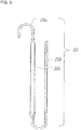
- Fig. 4 is a side view of the compressor and the injection pipe of the compressor unit of Embodiment 1 of the present invention.
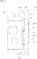
- Fig. 5 is a diagram illustrating a mounting mechanism for the injection muffler of Embodiment 1 of the present invention.
- the injection pipe 25 is disposed such that the injection muffler 25c runs along an outer circumferential surface of the shell 6, namely a side of the compressor 21.
- the compressor connecting part 25a is directed upward from a point where the compressor connecting part 25a is connected to the compressor 21, is then bent in a lateral direction, and further bent to be directed downward. That is, the compressor connecting part 25a is bent twice to have a reverse U-shape as a whole.
- the injection muffler 25c which is continuous to the compressor connecting part 25a, runs in a vertical direction along the outer circumferential surface of the shell 6 of the compressor 21.
- the expansion valve connecting part 25b which is continuous to the injection muffler 25c, extends downward from a point where the expansion valve connecting part 25b is connected with the injection muffler 25c, is then bent in a lateral direction, and is further bent to be directed upward. That is, the injection muffler 25c is bent twice to have a U-shaped portion. The upwardly bent portion runs up to the LEV 27. In this way, in Embodiment 1, the injection pipe 25 is bent four times in total.
- a vertically-extending portion of the compressor connecting part 25a, a vertically-extending portion of the expansion valve connecting part 25b and the injection muffler 25c each run parallel to an axial center of the compressor 21.
- the injection muffler 25c is fixed to the outer circumferential surface of the shell 6 of the compressor 21 at two points each by the mounting mechanism 30.
- Fig. 5 is a diagram illustrating the mounting mechanism for the injection muffler of Embodiment 1 of the present invention.
- the mounting mechanism 30 includes a fixed sheet metal 31 and a holding sheet metal 32.
- the fixed sheet metal 31 is a thin plate member with a substantially U-shaped cross section, and fixed to the outer circumferential surface of the shell 6 by welding.
- the fixed sheet metal 31 includes a pair of sides 31a, 31b extending in parallel to each other, and a mounting surface 31c connecting the pair of sides 31a, 31b.
- the fixed sheet metal 31 is disposed on the outer circumferential surface of the shell 6 such that the sides 31a, 31b run in the vertical direction.
- the holding sheet metal 32 is a belt-like member, and has a protrusion in its substantially central part in a longitudinal direction.
- the holding sheet metal 32 includes a holding part 32c between right and left ends 32a, 32b.
- the holding part 32c has a shape corresponding to a part of a cylindrical member.
- the holding sheet metal 32 is placed on the mounting surface 31c of the fixed sheet metal 31, and the injection muffler 25c is held between the mounting surface 31c of the fixed sheet metal 31 and the holding part 32c of the holding sheet metal 32.
- the end 32a of the holding sheet metal 32 is fixed to the mounting surface 31c of the fixed sheet metal 31 with a screw 41, and the end 32b of the holding sheet metal 32 is fixed to the mounting surface 31c of the fixed sheet metal 31 with a screw 42.
- the structure of the injection muffler 25c will be explained. Enlarging an inner diameter of the injection muffler 25c allows a volume inside the injection muffler 25c to be secured easily, which in turn allows easy reduction in pulsations.
- the injection muffler 25c may be difficult to install depending on its size due to limited space being available for fixing the injection muffler 25c inside a housing of the air-conditioning device 100.
- unnecessary increase in inner diameter of the injection muffler 25c increases a weight of the injection muffler 25c, which may lead to increased vibrations. Accordingly, it is important to identify a minimum volume required to reduce pulsations before determining an inner diameter and a total length of the injection muffler 25c.
- a diameter of the injection port 1b is set to ⁇ port
- an inner diameter of a distal end 250a of the injection pipe 25 that is continuous to the compressor connecting part 25a and disposed inside the compressor 21 is set to ⁇ inj
- the inner diameter of the compressor connecting part 25a of the injection pipe 25 is set to ⁇ d1
- the inner diameter of the expansion valve connecting part 25b of the injection pipe 25 is set to ⁇ d2
- the inner diameter of the injection muffler 25c is set to ⁇ muff.
- the injection pipe 25 is formed so as to satisfy relationships of ⁇ port ⁇ ⁇ inj ⁇ ⁇ d1 ⁇ ⁇ muff and ⁇ inj ⁇ ⁇ d2 ⁇ ⁇ muff.
- the injection muffler 25c having a larger inner diameter than the inner diameters of the compressor connecting part 25a and the expansion valve connecting part 25b fixed to injection pipe 25 enables a reduction of injection pulsations.
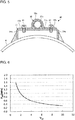
- Fig. 6 is a graph illustrating a correlation between a volume of the injection muffler and an amplitude of a pulsation generated in the injection pipe.
- a horizontal axis represents a ratio Vrat of an injection muffler volume Vmuff to a compressor displacement volume Vst (Vmuff / Vst)
- a vertical axis represents a difference Pdiff of a maximum value Pmax and a minimum value Pmin (Pmax - Pmin) of pulsations generated in the injection pipe.
- the injection muffler 25c that reduces pulsations generated in the injection pipe 25, it is necessary to identify an injection muffler volume required to reduce a pulsation amplitude.
- Pdiff tends to decrease as Vrat increases, and when Vrat is 3, Pdiff can be decreased by 50% or more as compared to when Vrat is 1.
- Vrat exceeds 4, Pdiff shows smaller changes.
- Increase in Vrat means an increase in size of the injection muffler itself, which may result in difficulty in installing the injection muffler or increased vibrations of the injection muffler itself; unnecessary enlargement of the injection muffler should thus be avoided. Therefore, the injection muffler 25c of Embodiment 1 is formed to satisfy a relationship of 3 ⁇ Vrat ⁇ 5.
- Fig. 7 is a diagram illustrating a compressor unit of Embodiment 2 of the present invention.
- the compressor unit 102 of Embodiment 2 includes an injection muffler 25d at a portion of the expansion valve connecting part 25b running upward to the LEV 27, in addition to the injection muffler 25c.
- each of the injection muffler 25c and the injection muffler 25d is fixed to the outer circumferential surface of the compressor 21 at two points each by the mounting mechanism 30.
- pulsations generated in the injection pipe 25 are so large that it may be difficult to reduce pulsations with the single injection muffler 25c alone.
- the injection muffler 25d to the expansion valve connecting part 25b, which is bent upward from a lower portion of the compressor 21, pulsations may be reduced even under conditions where pulsations increase.
- installing the two injection mufflers ensures injection muffler volumes while using less space to dispose the compressor inside the housing of the air-conditioning apparatus. This increases flexibility in configurations inside the air-conditioning apparatus.
- the injection muffler volume Vmuff is a sum of volumes of pipes and constituent components intended to produce the muffler effect.
- the injection muffler 25c and the injection muffler 25d are securely held on the outer circumferential surface of the shell 6 of the compressor 21 each through the mounting mechanism 30. This reduces pulsations and vibrations generated in the injection pipe 25, preventing cracking of the pipe.
- the holding sheet metal 32 by which the injection mufflers 25c, 25d are held is fixed to the fixed sheet metal 31, which is fixed to the outer circumferential surface of the shell 6 of the compressor 21, with the screws 41, 42.
- the holding sheet metal 32 is detachable from the fixed sheet metal 31. This allows easy removal of the injection pipe 25 for replacement when there are problems with the injection pipe 25.
- the mounting mechanism 30 is structured such that the holding sheet metal 32 is fixed to the fixed sheet metal 31 with the screws 41 and 42 in a state where the injection mufflers 25c and 25d are each held between the mounting surface 31c of the fixed sheet metal 31 and the holding part 32c of the holding sheet metal 32. This allows easy attachment or removal of the injection mufflers 25c, 25d by tightening or loosening the screws 41 and 42, resulting in good workability.
- the injection pipe 25 is bent at four points; however, the way of bending the injection pipe 25 is not limited to this.
- the injection pipe 25 may be bent as appropriate in consideration of space limitations inside the housing of the air-conditioning apparatus or other apparatuses in which the compressor units 101 and 102 are installed as well as installation positions of the injection mufflers 25c and 25d.
- Fig. 8 is a diagram illustrating a modified example of the mounting mechanism for the injection muffler of Embodiment 1.
- the mounting mechanism 130 includes a fixed sheet metal 131 and a holding sheet metal 132.
- the fixed sheet metal 131 is an element of a substantially cuboid shape and fixed to the outer circumferential surface of the shell 6 by welding.
- a surface of the fixed sheet metal 131 that is in contact with the shell 6 is formed in an arc shape conforming to the outer circumferential surface of the shell 6.
- a surface of the fixed sheet metal 131 opposite to the surface in contact with the shell 6 is provided with a pair of wall parts 131a, 131b extending in parallel to each other.
- the fixed sheet metal 131 thus has a U-shaped cross section.
- the fixed sheet metal 131 is disposed on the outer circumferential surface of the shell 6 such that the wall parts 131a, 131b run in the vertical direction.
- the holding sheet metal 132 includes a plate-like base part 132a and a cylindrical holding part 132b integrally formed with the base part 132a.
- the holding sheet metal 132 is fixed to the fixed sheet metal 131 with screws 141, 142 with the base part 132a being sandwiched between the pair of wall parts 131a, 131b of the fixed sheet metal 131 such that an axial center of the holding part 132b extends in the vertical direction.
- the injection muffler 25c is inserted through a hole 132c of the holding part 132b.
- the fixed sheet metal 131 being a substantially cuboid shaped member, the fixed sheet metal 131 is securely fixed to the outer circumferential surface of the shell 6 by welding.
- a holding sheet metal similar to the belt-like holding sheet metal 32 described above may be used to hold the injection muffler 25c between the substantially cuboid fixed sheet metal 131 and the belt-like holding sheet metal.
Landscapes
- Engineering & Computer Science (AREA)
- Mechanical Engineering (AREA)
- General Engineering & Computer Science (AREA)
- Physics & Mathematics (AREA)
- Thermal Sciences (AREA)
- Compressor (AREA)
- Applications Or Details Of Rotary Compressors (AREA)
- Rotary Pumps (AREA)
Description
- The present invention relates to a compressor unit installed in, among others, a refrigerating apparatus, an air-conditioning apparatus and a hot water supplier.
- A conventional refrigerating apparatus, air-conditioning apparatus or hot water supplier includes a compressor compressing refrigerant, a condenser rejecting heat from the compressed refrigerant, an expansion valve decreasing pressure of the refrigerant whose heat has been released and changing the refrigerant from liquid to gas, and an evaporator applying heat to adjust a refrigerant temperature to a target compressor suction temperature. Some compressors are equipped with an injection mechanism, in which a pipe is provided to permit a part of refrigerant flowing out of a condenser toward an evaporator to branch off and return to the compressor in a refrigerant circuit of an air-conditioning apparatus or other apparatuses. In the present description, this pipe is referred to as an injection pipe. The injection pipe is connected to an LEV (electronic linear expansion valve) of the refrigerant circuit. For example,
Patent Literature 1 discloses an injection pipe having an oil separating function disposed between an LEV and a compressor of an air-conditioning apparatus. - When the amount of refrigerant in the injection pipe injected into the compressor is large or when an injection mechanism is not operative, the refrigerant may flow back from the compressor, and this generates pulsations in the injection pipe. The injection pipe disclosed in
Patent Literature 1 is provided with a muffler at an end closer to the compressor to prevent damage or breakage of the injection pipe due to pulsations caused by flow-back of the refrigerant.Patent Literature 2 describes a screw compressor which includes an economizer circuit configured to eject intermediate pressure refrigerant into a compression chamber in the course of compression. -
- Patent Literature 1: Japanese Patent No.
5683075 page 6,Fig. 5 ) - Patent Literature 2: European Patent Application No.
2 634 432 A1 - However, the muffler disclosed in
Patent Literature 1 has an inner diameter twice as large as an inner diameter of the injection pipe and has a length ten times as large as the inner diameter of the injection pipe. For this reason, it is difficult to stably fix the muffler to the injection pipe, causing a drawback in that the muffler is installed with weak installation strength. With insufficient installation strength, the muffler is unable to prevent pulsations generated in the injection pipe, resulting in a problem that damage or breakage of the injection pipe cannot be surely prevented. - The present invention has been made to solve the above problem, and aims to prevent pulsations generated in the injection muffler and thereby to prevent damage or breakage of the injection pipe.
- The compressor unit of an embodiment of the present invention includes the features of
claim 1. Particularly, the compressor unit comprises a compressor, a condenser, and an injection pipe constituting a part of a refrigerant pipe connecting the compressor and the condenser, the injection pipe permitting a part of refrigerant flowing out of the condenser to branch off and flow into the compressor, wherein the injection pipe includes: a compressor connecting part connected to the compressor; an expansion valve connecting part connected to an expansion valve disposed in the injection pipe; and an injection muffler disposed between the compressor connecting part and the expansion valve connecting part, wherein the injection muffler has an inner diameter larger than an inner diameter of the compressor connecting part and an inner diameter of the expansion valve connecting part, and the injection muffler is fixed to a side of the compressor. - According to the compressor unit of an embodiment of the present invention, the injection muffler has an inner diameter larger than an inner diameter of the compressor connecting part and an inner diameter of the expansion valve connecting part of the injection pipe, and the injection muffler is fixed to a side of the compressor. This allows more effective prevention of pulsations caused by flow-back of the refrigerant, which in turn allows prevention of damage or breakage of the injection pipe.
-
- [
Fig. 1] Fig. 1 is a schematic block diagram of a refrigeration cycle of an air-conditioning apparatus ofEmbodiment 1 of the present invention. - [
Fig. 2] Fig. 2 is a schematic diagram illustrating a cross section of a compressor unit ofEmbodiment 1 of the present invention. - [
Fig. 3] Fig. 3 is a block diagram of an injection pipe ofEmbodiment 1 of the present invention. - [
Fig. 4] Fig. 4 is a side view of a compressor and the injection pipe of the compressor unit ofEmbodiment 1 of the present invention. - [
Fig. 5] Fig. 5 is a diagram illustrating a mounting mechanism for an injection muffler ofEmbodiment 1 of the present invention. - [
Fig. 6] Fig. 6 is a graph illustrating a correlation between a volume of the injection muffler and a pulsation amplitude generated in the injection pipe. - [
Fig. 7] Fig. 7 is a diagram illustrating a compressor unit ofEmbodiment 2 of the present invention. - [
Fig. 8] Fig. 8 is a diagram illustrating a modified example of the mounting mechanism for the injection muffler. - Hereinafter, embodiments of the compressor of the present invention will be explained in detail with reference to the drawings. In the present description, a closed scroll compressor is taken as an example. The compressor is a component of a refrigeration cycle of an apparatus such as a refrigerator, a freezer, an automatic vending machine, an air-conditioning apparatus, a refrigerating device and a hot water supplier. In the following drawings, size relationships among components may be different from actual ones.
-
Fig. 1 is a schematic block diagram of a refrigeration cycle of an air-conditioning apparatus ofEmbodiment 1 of the present invention.Fig. 2 is a schematic diagram of a cross section of a compressor unit ofEmbodiment 1 of the present invention. The air-conditioning device 100 includes acompressor 21, acondenser 22, an expansion valve 23, anevaporator 24, aninjection pipe 25, and anLEV 27. Thecompressor 21 sucks gas refrigerant and compresses it into a high-temperature and high-pressure state before discharging it to a refrigerant circuit. For example, the compressor is a closed scroll compressor. The high-temperature and high-pressure gas refrigerant discharged from thecompressor 21 flows into thecondenser 22. The high-temperature and high-pressure gas refrigerant having flowed into thecondenser 22 exchanges heat with air sent by a fan (not shown) disposed near thecondenser 22 and becomes a two-phase gas-liquid refrigerant before flowing out of thecondenser 22. The two-phase gas-liquid refrigerant having flowed out of thecondenser 22 is expanded and depressurized by the expansion valve 23 to become a low-temperature and low-pressure two-phase gas-liquid refrigerant. The low-temperature and low-pressure two-phase gas-liquid refrigerant flows into theevaporator 24. In theevaporator 24, the two-phase gas-liquid refrigerant exchanges heat with air supplied by a fan (not shown) disposed near theevaporator 24 and evaporates to become low-temperature and low-pressure gas refrigerant before flowing out of theevaporator 24. The low-temperature and low-pressure gas refrigerant having flowed out of theevaporator 24 is sucked into thecompressor 21. - A
compressor unit 101 includes thecompressor 21 and theinjection pipe 25. Thecompressor 21 includes ashell 6, which is a sealed container. Aframe 13 is disposed in an upper part of theshell 6, and asubframe 14 is disposed in a lower part of theshell 6. Theframe 13 and thesubframe 14 are fixed to an inner circumferential surface of theshell 6 by a method such as shrink-fitting and welding. A main bearing 13a is disposed in a through-hole formed in a central part of theframe 13, and anauxiliary bearing 14a is disposed in a through-hole formed in a central part of thesubframe 14. Acrank shaft 3 is rotatably supported by the main bearing 13a and the auxiliary bearing 14a. - A compression mechanism including a
fixed scroll 1 and an orbitingscroll 2 is disposed in the upper part of theshell 6. Thefixed scroll 1 is disposed above the orbitingscroll 2 and fixed to theshell 6 via theframe 13. The orbitingscroll 2 is disposed below thefixed scroll 1 and supported by thecrank shaft 3 such that theorbiting scroll 2 can orbit. Each of thefixed scroll 1 and theorbiting scroll 2 has a spiral element formed along an involute curve. Spiral elements of thefixed scroll 1 and theorbiting scroll 2 are engaged with each other to formplural compression chambers 7. - The
fixed scroll 1 is provided with aninjection port 1b. Also, astructural element 10 for connection with theinjection pipe 25 is detachably attached to thefixed scroll 1. The refrigerant led by theinjection pipe 25 is injected into thecompression chambers 7 via theinjection port 1b. - A driving mechanism including a
rotor 4 and astator 5 is disposed between theframe 13 and thesubframe 14. Thestator 5 is substantially cylindrical and an outer circumferential surface thereof is fixed to theshell 6 by a method such as shrink-fitting. Therotor 4 is fixed to an outer circumference of thecrank shaft 3 and has a permanent magnet inside. Therotor 4 is rotatably held inside thestator 5 with a slight gap from thestator 5. In response to thestator 5 being energized, therotor 4 is rotary-driven to rotate thecrank shaft 3. The rotation of therotor 4 transmits a rotary driving force to the above-described compression mechanism via thecrank shaft 3. In response to the rotary driving force being transmitted to the compression mechanism, theorbiting scroll 2 starts an orbiting movement. Along with the orbiting movement of theorbiting scroll 2, thecompression chambers 7 move to a center while reducing their volumes, thereby compressing the refrigerant. - The
shell 6 is provided with a suction pipe (not shown) for sucking refrigerant, and adischarge pipe 9 for discharging refrigerant. The refrigerant having flowed out of theevaporator 24 is sucked into the suction pipe and fills theshell 6. The refrigerant is then sucked into thecompression chambers 7, in which the refrigerant is compressed. Then, the refrigerant passes through a discharge port 1a and a connectingmember 8 connecting the discharge port 1a and thedischarge pipe 9 and is discharged from theshell 6 via thedischarge pipe 9. - The
injection pipe 25 permits a part of the refrigerant flowing out of thecondenser 22 to the expansion valve 23 to branch off and return to thecompression chambers 7 of thecompressor 21. Sending the two phase gas-liquid refrigerant to thecompression chambers 7 of thecompressor 21 prevents an excessive increase in temperature of the gas refrigerant discharged from thecompression chambers 7. -
Fig. 3 is a block diagram of an injection pipe ofEmbodiment 1 of the present invention. Theinjection pipe 25 includes acompressor connecting part 25a, an expansionvalve connecting part 25b, and aninjection muffler 25c. Thecompressor connecting part 25a is connected to thecompressor 21. The expansionvalve connecting part 25b is connected to theLEV 27. Theinjection muffler 25c is disposed between thecompressor connecting part 25a and the expansionvalve connecting part 25b. Each of thecompressor connecting part 25a, the expansionvalve connecting part 25b and theinjection muffler 25c has a cylindrical shape. As shown inFIG. 2 , thecompressor connecting part 25a, the expansionvalve connecting part 25b and theinjection muffler 25c are formed such that they satisfy relationships of φd1 ≤ φmuff and φd2 ≤ φmuff, where φd1 is an inner diameter (pipe diameter) of thecompressor connecting part 25a, φd2 is an inner diameter of the expansionvalve connecting part 25b and φmuff is an inner diameter of theinjection muffler 25c. - Compared to HFC refrigerant, which is used in many compressors, carbon dioxide refrigerant, for example, requires a large compression ratio to exhibit its capacity. For this reason, a pressure at which liquid refrigerant is discharged and a pressure at which refrigerant flows back from the
injection port 1b also increase. As a result, a pressure generated in theinjection pipe 25 also increases, and pulsations generated inside theinjection pipe 25 are magnified. - As the pulsations inside the
injection pipe 25 are magnified, vibrations generated inside theinjection pipe 25 increase, which may result in cracking of the pipe. In a fluid circuit, a sudden increase in pipe diameter from a certain pipe diameter produces a change in flow velocity and frequency. In view of this, inEmbodiment 1, theinjection muffler 25c having an inner diameter equal to or larger than inner diameters of thecompressor connecting part 25a and the expansionvalve connecting part 25b ofinjection pipe 25 is disposed in an injection circuit connecting thecompressor 21 and theLEV 27. This reduces pulsations generated inside theinjection pipe 25 even when the carbon dioxide refrigerant is used. -
Fig. 4 is a side view of the compressor and the injection pipe of the compressor unit ofEmbodiment 1 of the present invention.Fig. 5 is a diagram illustrating a mounting mechanism for the injection muffler ofEmbodiment 1 of the present invention. Theinjection pipe 25 is disposed such that theinjection muffler 25c runs along an outer circumferential surface of theshell 6, namely a side of thecompressor 21. Thecompressor connecting part 25a is directed upward from a point where thecompressor connecting part 25a is connected to thecompressor 21, is then bent in a lateral direction, and further bent to be directed downward. That is, thecompressor connecting part 25a is bent twice to have a reverse U-shape as a whole. Theinjection muffler 25c, which is continuous to thecompressor connecting part 25a, runs in a vertical direction along the outer circumferential surface of theshell 6 of thecompressor 21. The expansionvalve connecting part 25b, which is continuous to theinjection muffler 25c, extends downward from a point where the expansionvalve connecting part 25b is connected with theinjection muffler 25c, is then bent in a lateral direction, and is further bent to be directed upward. That is, theinjection muffler 25c is bent twice to have a U-shaped portion. The upwardly bent portion runs up to theLEV 27. In this way, inEmbodiment 1, theinjection pipe 25 is bent four times in total. - Also, a vertically-extending portion of the
compressor connecting part 25a, a vertically-extending portion of the expansionvalve connecting part 25b and theinjection muffler 25c each run parallel to an axial center of thecompressor 21. - The
injection muffler 25c is fixed to the outer circumferential surface of theshell 6 of thecompressor 21 at two points each by the mountingmechanism 30.Fig. 5 is a diagram illustrating the mounting mechanism for the injection muffler ofEmbodiment 1 of the present invention. The mountingmechanism 30 includes a fixedsheet metal 31 and a holdingsheet metal 32. The fixedsheet metal 31 is a thin plate member with a substantially U-shaped cross section, and fixed to the outer circumferential surface of theshell 6 by welding. The fixedsheet metal 31 includes a pair ofsides surface 31c connecting the pair ofsides sheet metal 31 is disposed on the outer circumferential surface of theshell 6 such that thesides - The holding
sheet metal 32 is a belt-like member, and has a protrusion in its substantially central part in a longitudinal direction. The holdingsheet metal 32 includes a holdingpart 32c between right and leftends part 32c has a shape corresponding to a part of a cylindrical member. The holdingsheet metal 32 is placed on the mountingsurface 31c of the fixedsheet metal 31, and theinjection muffler 25c is held between the mountingsurface 31c of the fixedsheet metal 31 and the holdingpart 32c of the holdingsheet metal 32. With theinjection muffler 25c being held between the mountingsurface 31c and the holdingpart 32c, theend 32a of the holdingsheet metal 32 is fixed to the mountingsurface 31c of the fixedsheet metal 31 with ascrew 41, and theend 32b of the holdingsheet metal 32 is fixed to the mountingsurface 31c of the fixedsheet metal 31 with ascrew 42. - Here, the structure of the
injection muffler 25c will be explained. Enlarging an inner diameter of theinjection muffler 25c allows a volume inside theinjection muffler 25c to be secured easily, which in turn allows easy reduction in pulsations. However, theinjection muffler 25c may be difficult to install depending on its size due to limited space being available for fixing theinjection muffler 25c inside a housing of the air-conditioning device 100. Also, unnecessary increase in inner diameter of theinjection muffler 25c increases a weight of theinjection muffler 25c, which may lead to increased vibrations. Accordingly, it is important to identify a minimum volume required to reduce pulsations before determining an inner diameter and a total length of theinjection muffler 25c. - In
Embodiment 1, as shown inFig. 2 , a diameter of theinjection port 1b is set to φport, an inner diameter of adistal end 250a of theinjection pipe 25 that is continuous to thecompressor connecting part 25a and disposed inside thecompressor 21 is set to φinj, the inner diameter of thecompressor connecting part 25a of theinjection pipe 25 is set to φd1, the inner diameter of the expansionvalve connecting part 25b of theinjection pipe 25 is set to φd2, and the inner diameter of theinjection muffler 25c is set to φmuff. InEmbodiment 1, theinjection pipe 25 is formed so as to satisfy relationships of φport ≤ φinj ≤ φd1 ≤ φmuff and φinj ≤ φd2 ≤ φmuff. In this way, theinjection muffler 25c having a larger inner diameter than the inner diameters of thecompressor connecting part 25a and the expansionvalve connecting part 25b fixed toinjection pipe 25 enables a reduction of injection pulsations. -
Fig. 6 is a graph illustrating a correlation between a volume of the injection muffler and an amplitude of a pulsation generated in the injection pipe. Referring toFig. 6 , an appropriate shape of theinjection muffler 25c with respect to a compressor displacement volume will be explained. In the graph ofFig. 6 , a horizontal axis represents a ratio Vrat of an injection muffler volume Vmuff to a compressor displacement volume Vst (Vmuff / Vst), and a vertical axis represents a difference Pdiff of a maximum value Pmax and a minimum value Pmin (Pmax - Pmin) of pulsations generated in the injection pipe. - To provide the
injection muffler 25c that reduces pulsations generated in theinjection pipe 25, it is necessary to identify an injection muffler volume required to reduce a pulsation amplitude. Pdiff tends to decrease as Vrat increases, and when Vrat is 3, Pdiff can be decreased by 50% or more as compared to when Vrat is 1. When Vrat exceeds 4, Pdiff shows smaller changes. Increase in Vrat means an increase in size of the injection muffler itself, which may result in difficulty in installing the injection muffler or increased vibrations of the injection muffler itself; unnecessary enlargement of the injection muffler should thus be avoided. Therefore, theinjection muffler 25c ofEmbodiment 1 is formed to satisfy a relationship of 3 ≤ Vrat ≤ 5. -
Fig. 7 is a diagram illustrating a compressor unit ofEmbodiment 2 of the present invention. As shown inFig. 7 , thecompressor unit 102 ofEmbodiment 2 includes aninjection muffler 25d at a portion of the expansionvalve connecting part 25b running upward to theLEV 27, in addition to theinjection muffler 25c. Similarly toEmbodiment 1 described above, each of theinjection muffler 25c and theinjection muffler 25d is fixed to the outer circumferential surface of thecompressor 21 at two points each by the mountingmechanism 30. - For example, in case of a compressor using refrigerant that is likely to be used under high-pressure conditions such as carbon dioxide refrigerant, pulsations generated in the
injection pipe 25 are so large that it may be difficult to reduce pulsations with thesingle injection muffler 25c alone. In this case, by adding theinjection muffler 25d to the expansionvalve connecting part 25b, which is bent upward from a lower portion of thecompressor 21, pulsations may be reduced even under conditions where pulsations increase. Further, even when a large diameter muffler cannot be installed due to limited space inside the air-conditioning device 100, installing the two injection mufflers ensures injection muffler volumes while using less space to dispose the compressor inside the housing of the air-conditioning apparatus. This increases flexibility in configurations inside the air-conditioning apparatus. - In
Embodiment 2, the injection muffler volume Vmuff is a sum of volumes of pipes and constituent components intended to produce the muffler effect. - In
Embodiments injection muffler 25c and theinjection muffler 25d are securely held on the outer circumferential surface of theshell 6 of thecompressor 21 each through the mountingmechanism 30. This reduces pulsations and vibrations generated in theinjection pipe 25, preventing cracking of the pipe. - In
Embodiments sheet metal 32 by which theinjection mufflers sheet metal 31, which is fixed to the outer circumferential surface of theshell 6 of thecompressor 21, with thescrews sheet metal 32 is detachable from the fixedsheet metal 31. This allows easy removal of theinjection pipe 25 for replacement when there are problems with theinjection pipe 25. - Also, the mounting
mechanism 30 is structured such that the holdingsheet metal 32 is fixed to the fixedsheet metal 31 with thescrews injection mufflers surface 31c of the fixedsheet metal 31 and the holdingpart 32c of the holdingsheet metal 32. This allows easy attachment or removal of theinjection mufflers screws - In
Embodiments injection pipe 25 is bent at four points; however, the way of bending theinjection pipe 25 is not limited to this. Theinjection pipe 25 may be bent as appropriate in consideration of space limitations inside the housing of the air-conditioning apparatus or other apparatuses in which thecompressor units injection mufflers - In
Embodiments injection muffler 25c is held between the mountingsurface 31c of the fixedsheet metal 31 and the holdingpart 32c of the holdingsheet metal 32; however, the way of holding theinjection muffler 25c is not limited to this.Fig. 8 is a diagram illustrating a modified example of the mounting mechanism for the injection muffler ofEmbodiment 1. The mountingmechanism 130 includes a fixedsheet metal 131 and a holdingsheet metal 132. The fixedsheet metal 131 is an element of a substantially cuboid shape and fixed to the outer circumferential surface of theshell 6 by welding. A surface of the fixedsheet metal 131 that is in contact with theshell 6 is formed in an arc shape conforming to the outer circumferential surface of theshell 6. A surface of the fixedsheet metal 131 opposite to the surface in contact with theshell 6 is provided with a pair ofwall parts sheet metal 131 thus has a U-shaped cross section. The fixedsheet metal 131 is disposed on the outer circumferential surface of theshell 6 such that thewall parts - The holding
sheet metal 132 includes a plate-like base part 132a and a cylindrical holdingpart 132b integrally formed with thebase part 132a. The holdingsheet metal 132 is fixed to the fixedsheet metal 131 withscrews base part 132a being sandwiched between the pair ofwall parts sheet metal 131 such that an axial center of the holdingpart 132b extends in the vertical direction. Theinjection muffler 25c is inserted through ahole 132c of the holdingpart 132b. In the modified example, by virtue of the fixedsheet metal 131 being a substantially cuboid shaped member, the fixedsheet metal 131 is securely fixed to the outer circumferential surface of theshell 6 by welding. This ensures rigidity enough to hold theinjection pipe 25. In this modified example, a holding sheet metal similar to the belt-likeholding sheet metal 32 described above may be used to hold theinjection muffler 25c between the substantially cuboid fixedsheet metal 131 and the belt-like holding sheet metal. -
- 1 fixed scroll
1a discharge port 1b injection port 2orbiting scroll 3 crankshaft 4rotor 5stator 6shell 7compression chamber 8 connectingelement 9 discharge pipe - 10
structure element 13frame 13amain bearing 14 subframe - 14a
auxiliary bearing 21compressor 22 condenser 23expansion valve 24evaporator 25injection pipe 25a compressor connecting part - 25b expansion
valve connecting part 25c injection muffler 25d injection muffler 27LEV 30mounting mechanism 31 fixedsheet metal 31aside 31b side31c mounting surface 32 holdingsheet 32c holding partmetal 32aend 32b end - 41
screw 42screw 100 air-conditioning device 101compressor unit 102compressor unit 130mounting mechanism 131 fixedsheet metal 131awall part 131b wall part 132 holdingsheet metal 132a base part 132b holding 141part 132c holescrew 142screw 250a distal end
Claims (6)
- A compressor unit (101) comprising:a compressor (21);a condenser (22); andan injection pipe (25) constituting a part of a refrigerant pipe connecting the compressor (21) and the condenser (22), the injection pipe permitting a part of refrigerant flowing out of the condenser (22) to branch off and flow into the compressor (21),wherein the injection pipe (25) includes:a compressor connecting part (25a) connected to the compressor (21);an expansion valve connecting part (25b) connected to an expansion valve (23) disposed in the injection pipe (25); andan injection muffler (25c) disposed between the compressor connecting part (25a) and the expansion valve connecting part (25b),characterized in that the injection muffler (25c) has an inner diameter larger than an inner diameter of the compressor connecting part (25a) and an inner diameter of the expansion valve connecting part (25b), and satisfies a relationship of 3 ≤ Vrat ≤ 5, where Vst is a compressor displacement volume, Vmuff is an injection muffler volume, and Vrat is a ratio of the injection muffler volume to the compressor displacement volume (Vmuff / Vst),and the injection muffler (25c) is fixed to a side of the compressor (21), whereinthe injection pipe (25) includes a distal end (250a) continuous to the compressor connecting part (25a) and disposed inside the compressor (21),the compressor (21) includes an injection port (1b) through which the refrigerant flowing into the compressor (21) via the distal end (250a) of the injection pipe (25) is led into a compression chamber (7) of the compressor (21),the injection pipe (25) satisfies relationships of φport ≤ φinj ≤ φd1 ≤ φmuff and φinj ≤ φd2 ≤ φmuff, where φport is an inner diameter of the injection port (1b), φinj is an inner diameter of the distal end (250a), φd1 is the inner diameter of the compressor connecting part (25a), φd2 is the inner diameter of the expansion valve connecting part (25b) and φmuff is the inner diameter of the injection muffler (25c).
- The compressor unit (101) of claim 1, wherein the injection pipe (25) is bent at four points, and the injection muffler (25c) is fixed to the compressor (21) at at least two points.
- The compressor unit (101) of any one of claims 1 or 2, further comprising a fixing mechanism (30) fixing the injection muffler (25c) to the compressor (21), wherein the fixing mechanism (30) includes a fixed part (31) fixed to the side of the compressor (21), and a holding part (32) holding the injection muffler (25c), and
the holding part (32) is detachably attached to the fixed part (31). - The compressor unit (101) of claim 3, wherein the fixed part (31) is welded to the side of the compressor (32).
- The compressor unit (101) of claim 3 or 4, wherein the holding part (32) is screwed to the fixed part (31).
- The compressor unit (101) of any one of claims 1 to 5, wherein the refrigerant is a carbon dioxide refrigerant.
Applications Claiming Priority (1)
| Application Number | Priority Date | Filing Date | Title |
|---|---|---|---|
| PCT/JP2016/064786 WO2017199380A1 (en) | 2016-05-18 | 2016-05-18 | Compressor unit |
Publications (3)
| Publication Number | Publication Date |
|---|---|
| EP3460244A1 EP3460244A1 (en) | 2019-03-27 |
| EP3460244A4 EP3460244A4 (en) | 2019-03-27 |
| EP3460244B1 true EP3460244B1 (en) | 2020-03-11 |
Family
ID=60325074
Family Applications (1)
| Application Number | Title | Priority Date | Filing Date |
|---|---|---|---|
| EP16902399.1A Active EP3460244B1 (en) | 2016-05-18 | 2016-05-18 | Compressor unit |
Country Status (4)
| Country | Link |
|---|---|
| EP (1) | EP3460244B1 (en) |
| JP (1) | JPWO2017199380A1 (en) |
| KR (1) | KR20180121623A (en) |
| WO (1) | WO2017199380A1 (en) |
Families Citing this family (1)
| Publication number | Priority date | Publication date | Assignee | Title |
|---|---|---|---|---|
| CN112761954A (en) * | 2021-02-01 | 2021-05-07 | 珠海格力节能环保制冷技术研究中心有限公司 | Exhaust silencing assembly, compressor and air conditioner |
Family Cites Families (6)
| Publication number | Priority date | Publication date | Assignee | Title |
|---|---|---|---|---|
| JPS61261693A (en) * | 1985-05-16 | 1986-11-19 | Mitsubishi Electric Corp | Scroll compressor |
| JP2003286945A (en) * | 2002-03-28 | 2003-10-10 | Sanyo Electric Co Ltd | Compressor |
| US20090116977A1 (en) * | 2007-11-02 | 2009-05-07 | Perevozchikov Michael M | Compressor With Muffler |
| JP5683075B2 (en) * | 2009-02-13 | 2015-03-11 | 三菱重工業株式会社 | Injection tube |
| US9086067B2 (en) * | 2010-10-29 | 2015-07-21 | Daikin Industries, Ltd. | Screw compressor |
| WO2014156743A1 (en) * | 2013-03-28 | 2014-10-02 | 三菱電機株式会社 | Scroll compressor and refrigeration cycle device comprising same |
-
2016
- 2016-05-18 EP EP16902399.1A patent/EP3460244B1/en active Active
- 2016-05-18 WO PCT/JP2016/064786 patent/WO2017199380A1/en not_active Ceased
- 2016-05-18 JP JP2018518008A patent/JPWO2017199380A1/en active Pending
- 2016-05-18 KR KR1020187029461A patent/KR20180121623A/en not_active Ceased
Non-Patent Citations (1)
| Title |
|---|
| None * |
Also Published As
| Publication number | Publication date |
|---|---|
| EP3460244A1 (en) | 2019-03-27 |
| JPWO2017199380A1 (en) | 2018-12-06 |
| WO2017199380A1 (en) | 2017-11-23 |
| KR20180121623A (en) | 2018-11-07 |
| EP3460244A4 (en) | 2019-03-27 |
Similar Documents
| Publication | Publication Date | Title |
|---|---|---|
| US9051934B2 (en) | Apparatus and method for oil equalization in multiple-compressor systems | |
| US10274233B2 (en) | Refrigerant cooling and lubrication system with refrigerant source access from an evaporator | |
| EP2594737A2 (en) | Rotary Compressor and Manufacturing Method Thereof | |
| WO2010092933A1 (en) | Injection pipe | |
| US9748815B2 (en) | Rotary compressor with the balance weight formed with a recess for receiving the head of a rivet | |
| US9404499B2 (en) | Dual chamber discharge muffler | |
| EP4390129A1 (en) | Compressor unit and refrigeration device | |
| EP3604813B1 (en) | Two-stage compressor | |
| EP3460244B1 (en) | Compressor unit | |
| EP3325807B1 (en) | Compressor bearing housing drain | |
| EP4411136A1 (en) | Compressor unit | |
| EP4177470B1 (en) | Heat source unit and scroll compressor | |
| CN112066582B (en) | Direct evaporation type magnetic suspension system and air conditioner with same | |
| JP2002295378A (en) | Scroll compressor and refrigeration cycle | |
| EP2716911A1 (en) | Hermetically-sealed compressor in which member for reducing discharge pulsations is installed | |
| EP1864839A1 (en) | Automotive air-conditioning system | |
| US9518574B2 (en) | Suction muffler for compressor | |
| KR20100083257A (en) | Device for preventing reverse rotation of compressor and method for controlling the same used in refrigerator unit and heat pump | |
| JP2014125914A (en) | Scroll compressor | |
| JP6935833B1 (en) | Scroll compressor, heat source unit | |
| EP3751142B1 (en) | Compressor and refrigeration cycle device | |
| KR200382915Y1 (en) | Accumulator connection structure of rotary compressor | |
| KR100520055B1 (en) | Accumulator for Refrigerator | |
| JP2008298413A (en) | Turbo refrigerator | |
| JP6749183B2 (en) | Scroll compressor |
Legal Events
| Date | Code | Title | Description |
|---|---|---|---|
| STAA | Information on the status of an ep patent application or granted ep patent |
Free format text: STATUS: THE INTERNATIONAL PUBLICATION HAS BEEN MADE |
|
| PUAI | Public reference made under article 153(3) epc to a published international application that has entered the european phase |
Free format text: ORIGINAL CODE: 0009012 |
|
| STAA | Information on the status of an ep patent application or granted ep patent |
Free format text: STATUS: REQUEST FOR EXAMINATION WAS MADE |
|
| 17P | Request for examination filed |
Effective date: 20181108 |
|
| A4 | Supplementary search report drawn up and despatched |
Effective date: 20190219 |
|
| AK | Designated contracting states |
Kind code of ref document: A1 Designated state(s): AL AT BE BG CH CY CZ DE DK EE ES FI FR GB GR HR HU IE IS IT LI LT LU LV MC MK MT NL NO PL PT RO RS SE SI SK SM TR |
|
| AX | Request for extension of the european patent |
Extension state: BA ME |
|
| DAV | Request for validation of the european patent (deleted) | ||
| DAX | Request for extension of the european patent (deleted) | ||
| REG | Reference to a national code |
Ref country code: DE Ref legal event code: R079 Ref document number: 602016031816 Country of ref document: DE Free format text: PREVIOUS MAIN CLASS: F04C0018020000 Ipc: F04C0029000000 |
|
| GRAP | Despatch of communication of intention to grant a patent |
Free format text: ORIGINAL CODE: EPIDOSNIGR1 |
|
| STAA | Information on the status of an ep patent application or granted ep patent |
Free format text: STATUS: GRANT OF PATENT IS INTENDED |
|
| RIC1 | Information provided on ipc code assigned before grant |
Ipc: F04C 18/02 20060101ALI20190917BHEP Ipc: F04C 29/06 20060101ALI20190917BHEP Ipc: F04C 29/00 20060101AFI20190917BHEP |
|
| INTG | Intention to grant announced |
Effective date: 20191007 |
|
| GRAS | Grant fee paid |
Free format text: ORIGINAL CODE: EPIDOSNIGR3 |
|
| GRAA | (expected) grant |
Free format text: ORIGINAL CODE: 0009210 |
|
| STAA | Information on the status of an ep patent application or granted ep patent |
Free format text: STATUS: THE PATENT HAS BEEN GRANTED |
|
| AK | Designated contracting states |
Kind code of ref document: B1 Designated state(s): AL AT BE BG CH CY CZ DE DK EE ES FI FR GB GR HR HU IE IS IT LI LT LU LV MC MK MT NL NO PL PT RO RS SE SI SK SM TR |
|
| REG | Reference to a national code |
Ref country code: GB Ref legal event code: FG4D |
|
| REG | Reference to a national code |
Ref country code: CH Ref legal event code: EP |
|
| REG | Reference to a national code |
Ref country code: AT Ref legal event code: REF Ref document number: 1243450 Country of ref document: AT Kind code of ref document: T Effective date: 20200315 |
|
| REG | Reference to a national code |
Ref country code: IE Ref legal event code: FG4D |
|
| REG | Reference to a national code |
Ref country code: DE Ref legal event code: R096 Ref document number: 602016031816 Country of ref document: DE |
|
| PG25 | Lapsed in a contracting state [announced via postgrant information from national office to epo] |
Ref country code: RS Free format text: LAPSE BECAUSE OF FAILURE TO SUBMIT A TRANSLATION OF THE DESCRIPTION OR TO PAY THE FEE WITHIN THE PRESCRIBED TIME-LIMIT Effective date: 20200311 Ref country code: FI Free format text: LAPSE BECAUSE OF FAILURE TO SUBMIT A TRANSLATION OF THE DESCRIPTION OR TO PAY THE FEE WITHIN THE PRESCRIBED TIME-LIMIT Effective date: 20200311 Ref country code: NO Free format text: LAPSE BECAUSE OF FAILURE TO SUBMIT A TRANSLATION OF THE DESCRIPTION OR TO PAY THE FEE WITHIN THE PRESCRIBED TIME-LIMIT Effective date: 20200611 |
|
| REG | Reference to a national code |
Ref country code: NL Ref legal event code: MP Effective date: 20200311 |
|
| PG25 | Lapsed in a contracting state [announced via postgrant information from national office to epo] |
Ref country code: LV Free format text: LAPSE BECAUSE OF FAILURE TO SUBMIT A TRANSLATION OF THE DESCRIPTION OR TO PAY THE FEE WITHIN THE PRESCRIBED TIME-LIMIT Effective date: 20200311 Ref country code: SE Free format text: LAPSE BECAUSE OF FAILURE TO SUBMIT A TRANSLATION OF THE DESCRIPTION OR TO PAY THE FEE WITHIN THE PRESCRIBED TIME-LIMIT Effective date: 20200311 Ref country code: GR Free format text: LAPSE BECAUSE OF FAILURE TO SUBMIT A TRANSLATION OF THE DESCRIPTION OR TO PAY THE FEE WITHIN THE PRESCRIBED TIME-LIMIT Effective date: 20200612 Ref country code: HR Free format text: LAPSE BECAUSE OF FAILURE TO SUBMIT A TRANSLATION OF THE DESCRIPTION OR TO PAY THE FEE WITHIN THE PRESCRIBED TIME-LIMIT Effective date: 20200311 Ref country code: BG Free format text: LAPSE BECAUSE OF FAILURE TO SUBMIT A TRANSLATION OF THE DESCRIPTION OR TO PAY THE FEE WITHIN THE PRESCRIBED TIME-LIMIT Effective date: 20200611 |
|
| REG | Reference to a national code |
Ref country code: LT Ref legal event code: MG4D |
|
| PG25 | Lapsed in a contracting state [announced via postgrant information from national office to epo] |
Ref country code: NL Free format text: LAPSE BECAUSE OF FAILURE TO SUBMIT A TRANSLATION OF THE DESCRIPTION OR TO PAY THE FEE WITHIN THE PRESCRIBED TIME-LIMIT Effective date: 20200311 |
|
| PG25 | Lapsed in a contracting state [announced via postgrant information from national office to epo] |
Ref country code: LT Free format text: LAPSE BECAUSE OF FAILURE TO SUBMIT A TRANSLATION OF THE DESCRIPTION OR TO PAY THE FEE WITHIN THE PRESCRIBED TIME-LIMIT Effective date: 20200311 Ref country code: IS Free format text: LAPSE BECAUSE OF FAILURE TO SUBMIT A TRANSLATION OF THE DESCRIPTION OR TO PAY THE FEE WITHIN THE PRESCRIBED TIME-LIMIT Effective date: 20200711 Ref country code: SK Free format text: LAPSE BECAUSE OF FAILURE TO SUBMIT A TRANSLATION OF THE DESCRIPTION OR TO PAY THE FEE WITHIN THE PRESCRIBED TIME-LIMIT Effective date: 20200311 Ref country code: PT Free format text: LAPSE BECAUSE OF FAILURE TO SUBMIT A TRANSLATION OF THE DESCRIPTION OR TO PAY THE FEE WITHIN THE PRESCRIBED TIME-LIMIT Effective date: 20200805 Ref country code: CZ Free format text: LAPSE BECAUSE OF FAILURE TO SUBMIT A TRANSLATION OF THE DESCRIPTION OR TO PAY THE FEE WITHIN THE PRESCRIBED TIME-LIMIT Effective date: 20200311 Ref country code: RO Free format text: LAPSE BECAUSE OF FAILURE TO SUBMIT A TRANSLATION OF THE DESCRIPTION OR TO PAY THE FEE WITHIN THE PRESCRIBED TIME-LIMIT Effective date: 20200311 Ref country code: SM Free format text: LAPSE BECAUSE OF FAILURE TO SUBMIT A TRANSLATION OF THE DESCRIPTION OR TO PAY THE FEE WITHIN THE PRESCRIBED TIME-LIMIT Effective date: 20200311 Ref country code: EE Free format text: LAPSE BECAUSE OF FAILURE TO SUBMIT A TRANSLATION OF THE DESCRIPTION OR TO PAY THE FEE WITHIN THE PRESCRIBED TIME-LIMIT Effective date: 20200311 |
|
| REG | Reference to a national code |
Ref country code: AT Ref legal event code: MK05 Ref document number: 1243450 Country of ref document: AT Kind code of ref document: T Effective date: 20200311 |
|
| REG | Reference to a national code |
Ref country code: DE Ref legal event code: R097 Ref document number: 602016031816 Country of ref document: DE |
|
| PLBE | No opposition filed within time limit |
Free format text: ORIGINAL CODE: 0009261 |
|
| STAA | Information on the status of an ep patent application or granted ep patent |
Free format text: STATUS: NO OPPOSITION FILED WITHIN TIME LIMIT |
|
| PG25 | Lapsed in a contracting state [announced via postgrant information from national office to epo] |
Ref country code: CH Free format text: LAPSE BECAUSE OF NON-PAYMENT OF DUE FEES Effective date: 20200531 Ref country code: ES Free format text: LAPSE BECAUSE OF FAILURE TO SUBMIT A TRANSLATION OF THE DESCRIPTION OR TO PAY THE FEE WITHIN THE PRESCRIBED TIME-LIMIT Effective date: 20200311 Ref country code: LI Free format text: LAPSE BECAUSE OF NON-PAYMENT OF DUE FEES Effective date: 20200531 Ref country code: MC Free format text: LAPSE BECAUSE OF FAILURE TO SUBMIT A TRANSLATION OF THE DESCRIPTION OR TO PAY THE FEE WITHIN THE PRESCRIBED TIME-LIMIT Effective date: 20200311 Ref country code: DK Free format text: LAPSE BECAUSE OF FAILURE TO SUBMIT A TRANSLATION OF THE DESCRIPTION OR TO PAY THE FEE WITHIN THE PRESCRIBED TIME-LIMIT Effective date: 20200311 Ref country code: AT Free format text: LAPSE BECAUSE OF FAILURE TO SUBMIT A TRANSLATION OF THE DESCRIPTION OR TO PAY THE FEE WITHIN THE PRESCRIBED TIME-LIMIT Effective date: 20200311 |
|
| 26N | No opposition filed |
Effective date: 20201214 |
|
| PG25 | Lapsed in a contracting state [announced via postgrant information from national office to epo] |
Ref country code: SI Free format text: LAPSE BECAUSE OF FAILURE TO SUBMIT A TRANSLATION OF THE DESCRIPTION OR TO PAY THE FEE WITHIN THE PRESCRIBED TIME-LIMIT Effective date: 20200311 Ref country code: PL Free format text: LAPSE BECAUSE OF FAILURE TO SUBMIT A TRANSLATION OF THE DESCRIPTION OR TO PAY THE FEE WITHIN THE PRESCRIBED TIME-LIMIT Effective date: 20200311 |
|
| REG | Reference to a national code |
Ref country code: BE Ref legal event code: MM Effective date: 20200531 |
|
| PG25 | Lapsed in a contracting state [announced via postgrant information from national office to epo] |
Ref country code: LU Free format text: LAPSE BECAUSE OF NON-PAYMENT OF DUE FEES Effective date: 20200518 |
|
| PG25 | Lapsed in a contracting state [announced via postgrant information from national office to epo] |
Ref country code: IE Free format text: LAPSE BECAUSE OF NON-PAYMENT OF DUE FEES Effective date: 20200518 Ref country code: FR Free format text: LAPSE BECAUSE OF NON-PAYMENT OF DUE FEES Effective date: 20200531 |
|
| PG25 | Lapsed in a contracting state [announced via postgrant information from national office to epo] |
Ref country code: BE Free format text: LAPSE BECAUSE OF NON-PAYMENT OF DUE FEES Effective date: 20200531 |
|
| PG25 | Lapsed in a contracting state [announced via postgrant information from national office to epo] |
Ref country code: TR Free format text: LAPSE BECAUSE OF FAILURE TO SUBMIT A TRANSLATION OF THE DESCRIPTION OR TO PAY THE FEE WITHIN THE PRESCRIBED TIME-LIMIT Effective date: 20200311 Ref country code: MT Free format text: LAPSE BECAUSE OF FAILURE TO SUBMIT A TRANSLATION OF THE DESCRIPTION OR TO PAY THE FEE WITHIN THE PRESCRIBED TIME-LIMIT Effective date: 20200311 Ref country code: CY Free format text: LAPSE BECAUSE OF FAILURE TO SUBMIT A TRANSLATION OF THE DESCRIPTION OR TO PAY THE FEE WITHIN THE PRESCRIBED TIME-LIMIT Effective date: 20200311 |
|
| PG25 | Lapsed in a contracting state [announced via postgrant information from national office to epo] |
Ref country code: MK Free format text: LAPSE BECAUSE OF FAILURE TO SUBMIT A TRANSLATION OF THE DESCRIPTION OR TO PAY THE FEE WITHIN THE PRESCRIBED TIME-LIMIT Effective date: 20200311 Ref country code: AL Free format text: LAPSE BECAUSE OF FAILURE TO SUBMIT A TRANSLATION OF THE DESCRIPTION OR TO PAY THE FEE WITHIN THE PRESCRIBED TIME-LIMIT Effective date: 20200311 |
|
| REG | Reference to a national code |
Ref country code: DE Ref legal event code: R084 Ref document number: 602016031816 Country of ref document: DE |
|
| REG | Reference to a national code |
Ref country code: GB Ref legal event code: 746 Effective date: 20230103 |
|
| P01 | Opt-out of the competence of the unified patent court (upc) registered |
Effective date: 20230512 |
|
| PGFP | Annual fee paid to national office [announced via postgrant information from national office to epo] |
Ref country code: IT Payment date: 20240411 Year of fee payment: 9 |
|
| PGFP | Annual fee paid to national office [announced via postgrant information from national office to epo] |
Ref country code: GB Payment date: 20250327 Year of fee payment: 10 |
|
| PGFP | Annual fee paid to national office [announced via postgrant information from national office to epo] |
Ref country code: DE Payment date: 20250402 Year of fee payment: 10 |