EP3460196B1 - Lageranordnung für eine variable leitschaufel - Google Patents
Lageranordnung für eine variable leitschaufel Download PDFInfo
- Publication number
- EP3460196B1 EP3460196B1 EP18189680.4A EP18189680A EP3460196B1 EP 3460196 B1 EP3460196 B1 EP 3460196B1 EP 18189680 A EP18189680 A EP 18189680A EP 3460196 B1 EP3460196 B1 EP 3460196B1
- Authority
- EP
- European Patent Office
- Prior art keywords
- bush
- shaft
- bearing
- inner shroud
- variable stator
- Prior art date
- Legal status (The legal status is an assumption and is not a legal conclusion. Google has not performed a legal analysis and makes no representation as to the accuracy of the status listed.)
- Active
Links
- 238000000034 method Methods 0.000 claims description 13
- 238000004519 manufacturing process Methods 0.000 claims description 5
- 230000000712 assembly Effects 0.000 claims description 4
- 238000000429 assembly Methods 0.000 claims description 4
- 230000006835 compression Effects 0.000 claims description 4
- 238000007906 compression Methods 0.000 claims description 4
- 239000007787 solid Substances 0.000 claims description 3
- 238000002485 combustion reaction Methods 0.000 description 3
- 230000001141 propulsive effect Effects 0.000 description 3
- 239000000463 material Substances 0.000 description 2
- 229910052751 metal Inorganic materials 0.000 description 2
- 239000002184 metal Substances 0.000 description 2
- 229920000642 polymer Polymers 0.000 description 2
- 229910000838 Al alloy Inorganic materials 0.000 description 1
- 229910000851 Alloy steel Inorganic materials 0.000 description 1
- 229910000990 Ni alloy Inorganic materials 0.000 description 1
- 229910001069 Ti alloy Inorganic materials 0.000 description 1
- RTAQQCXQSZGOHL-UHFFFAOYSA-N Titanium Chemical compound [Ti] RTAQQCXQSZGOHL-UHFFFAOYSA-N 0.000 description 1
- 239000004411 aluminium Substances 0.000 description 1
- XAGFODPZIPBFFR-UHFFFAOYSA-N aluminium Chemical compound [Al] XAGFODPZIPBFFR-UHFFFAOYSA-N 0.000 description 1
- 239000000470 constituent Substances 0.000 description 1
- 238000013016 damping Methods 0.000 description 1
- 230000005489 elastic deformation Effects 0.000 description 1
- 239000013536 elastomeric material Substances 0.000 description 1
- 239000000446 fuel Substances 0.000 description 1
- 239000000203 mixture Substances 0.000 description 1
- 238000012986 modification Methods 0.000 description 1
- 230000004048 modification Effects 0.000 description 1
- 230000006641 stabilisation Effects 0.000 description 1
- 238000011105 stabilization Methods 0.000 description 1
- 230000003068 static effect Effects 0.000 description 1
- 239000010959 steel Substances 0.000 description 1
- 239000010936 titanium Substances 0.000 description 1
Images


Classifications
-
- F—MECHANICAL ENGINEERING; LIGHTING; HEATING; WEAPONS; BLASTING
- F16—ENGINEERING ELEMENTS AND UNITS; GENERAL MEASURES FOR PRODUCING AND MAINTAINING EFFECTIVE FUNCTIONING OF MACHINES OR INSTALLATIONS; THERMAL INSULATION IN GENERAL
- F16C—SHAFTS; FLEXIBLE SHAFTS; ELEMENTS OR CRANKSHAFT MECHANISMS; ROTARY BODIES OTHER THAN GEARING ELEMENTS; BEARINGS
- F16C33/00—Parts of bearings; Special methods for making bearings or parts thereof
- F16C33/02—Parts of sliding-contact bearings
- F16C33/04—Brasses; Bushes; Linings
- F16C33/06—Sliding surface mainly made of metal
- F16C33/08—Attachment of brasses, bushes or linings to the bearing housing
-
- F—MECHANICAL ENGINEERING; LIGHTING; HEATING; WEAPONS; BLASTING
- F01—MACHINES OR ENGINES IN GENERAL; ENGINE PLANTS IN GENERAL; STEAM ENGINES
- F01D—NON-POSITIVE DISPLACEMENT MACHINES OR ENGINES, e.g. STEAM TURBINES
- F01D17/00—Regulating or controlling by varying flow
- F01D17/10—Final actuators
- F01D17/12—Final actuators arranged in stator parts
- F01D17/14—Final actuators arranged in stator parts varying effective cross-sectional area of nozzles or guide conduits
- F01D17/16—Final actuators arranged in stator parts varying effective cross-sectional area of nozzles or guide conduits by means of nozzle vanes
- F01D17/162—Final actuators arranged in stator parts varying effective cross-sectional area of nozzles or guide conduits by means of nozzle vanes for axial flow, i.e. the vanes turning around axes which are essentially perpendicular to the rotor centre line
-
- F—MECHANICAL ENGINEERING; LIGHTING; HEATING; WEAPONS; BLASTING
- F16—ENGINEERING ELEMENTS AND UNITS; GENERAL MEASURES FOR PRODUCING AND MAINTAINING EFFECTIVE FUNCTIONING OF MACHINES OR INSTALLATIONS; THERMAL INSULATION IN GENERAL
- F16C—SHAFTS; FLEXIBLE SHAFTS; ELEMENTS OR CRANKSHAFT MECHANISMS; ROTARY BODIES OTHER THAN GEARING ELEMENTS; BEARINGS
- F16C17/00—Sliding-contact bearings for exclusively rotary movement
- F16C17/02—Sliding-contact bearings for exclusively rotary movement for radial load only
-
- F—MECHANICAL ENGINEERING; LIGHTING; HEATING; WEAPONS; BLASTING
- F04—POSITIVE - DISPLACEMENT MACHINES FOR LIQUIDS; PUMPS FOR LIQUIDS OR ELASTIC FLUIDS
- F04D—NON-POSITIVE-DISPLACEMENT PUMPS
- F04D29/00—Details, component parts, or accessories
- F04D29/40—Casings; Connections of working fluid
- F04D29/52—Casings; Connections of working fluid for axial pumps
- F04D29/54—Fluid-guiding means, e.g. diffusers
- F04D29/56—Fluid-guiding means, e.g. diffusers adjustable
- F04D29/563—Fluid-guiding means, e.g. diffusers adjustable specially adapted for elastic fluid pumps
-
- F—MECHANICAL ENGINEERING; LIGHTING; HEATING; WEAPONS; BLASTING
- F05—INDEXING SCHEMES RELATING TO ENGINES OR PUMPS IN VARIOUS SUBCLASSES OF CLASSES F01-F04
- F05D—INDEXING SCHEME FOR ASPECTS RELATING TO NON-POSITIVE-DISPLACEMENT MACHINES OR ENGINES, GAS-TURBINES OR JET-PROPULSION PLANTS
- F05D2240/00—Components
- F05D2240/50—Bearings
-
- F—MECHANICAL ENGINEERING; LIGHTING; HEATING; WEAPONS; BLASTING
- F16—ENGINEERING ELEMENTS AND UNITS; GENERAL MEASURES FOR PRODUCING AND MAINTAINING EFFECTIVE FUNCTIONING OF MACHINES OR INSTALLATIONS; THERMAL INSULATION IN GENERAL
- F16C—SHAFTS; FLEXIBLE SHAFTS; ELEMENTS OR CRANKSHAFT MECHANISMS; ROTARY BODIES OTHER THAN GEARING ELEMENTS; BEARINGS
- F16C2360/00—Engines or pumps
- F16C2360/23—Gas turbine engines
-
- F—MECHANICAL ENGINEERING; LIGHTING; HEATING; WEAPONS; BLASTING
- F16—ENGINEERING ELEMENTS AND UNITS; GENERAL MEASURES FOR PRODUCING AND MAINTAINING EFFECTIVE FUNCTIONING OF MACHINES OR INSTALLATIONS; THERMAL INSULATION IN GENERAL
- F16C—SHAFTS; FLEXIBLE SHAFTS; ELEMENTS OR CRANKSHAFT MECHANISMS; ROTARY BODIES OTHER THAN GEARING ELEMENTS; BEARINGS
- F16C35/00—Rigid support of bearing units; Housings, e.g. caps, covers
- F16C35/02—Rigid support of bearing units; Housings, e.g. caps, covers in the case of sliding-contact bearings
-
- F—MECHANICAL ENGINEERING; LIGHTING; HEATING; WEAPONS; BLASTING
- F16—ENGINEERING ELEMENTS AND UNITS; GENERAL MEASURES FOR PRODUCING AND MAINTAINING EFFECTIVE FUNCTIONING OF MACHINES OR INSTALLATIONS; THERMAL INSULATION IN GENERAL
- F16C—SHAFTS; FLEXIBLE SHAFTS; ELEMENTS OR CRANKSHAFT MECHANISMS; ROTARY BODIES OTHER THAN GEARING ELEMENTS; BEARINGS
- F16C43/00—Assembling bearings
- F16C43/02—Assembling sliding-contact bearings
Definitions
- the present disclosure concerns a bearing arrangement, a bearing assembly, a set of variable stator vanes for a gas turbine engine and a method of manufacturing a set of variable stator vanes.
- Gas turbine engines comprise compressors that impart energy to the air flowing through the engine.
- Compressors may comprise rotors and stators.
- the stators are used to reduce swirl and achieve a rise in static pressure.
- VSVs Variable Stator Vanes
- Polymer bushes may be used to minimise friction between such VSVs and the casing in which they are mounted, as the vane incidence angle is varied.
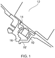
- Figure 1 shows a typical bearing arrangement for a VSV.
- parts 16 and 16' form the housing for the bush 10.
- a shaft 14 extends from the variable stator vane 12, and the shaft 14 is received by the bush 10 and rotates against it.
- the bush 10 and housing 16, 16' resist radial forces experienced by the variable stator vane 12 about its own axis of rotation.
- United States patent US 9410443 B2 discloses a variable vane damping assembly that includes an inner bushing and an outer bushing.
- the inner bushing comprises an elastomeric material.
- European patent application EP 2716874 A1 discloses a guide blade assembly that has multiple rotatable guide blades, an inner ring with two half-rings for radial inner stabilization of the guide blades, and a circular seal carrier.
- the shaped elements are inserted in opposite recesses of the half ring segments, which cooperate with wall sections of the recesses in a form-fit or force-fit manner.
- the half ring segments have a centering section, on which a guide blade is guided in each case. A method for mounting such a guide blade assembly is also described.
- United States patent application US 2014/234085 A1 discloses a variable area vane arrangement that includes a stator vane, a bushing and a vane platform with an aperture.
- the stator vane rotates about an axis, and includes a shaft that extends along the axis into the aperture.
- the bushing is connected to the shaft, and is arranged within the aperture between the vane platform and the shaft.
- Variable stator vane bushes are subject to wear due to the bearing forces and rotation. It is desirable to have an improved wear resistant variable stator vane bush that fits within the assembly constraints of the variable stator vane assembly.
- the present disclosure provides a bearing arrangement for variable stator vanes for a gas turbine engine, a bearing assembly, a set of variable stator vanes for a gas turbine engine, a gas turbine engine, and a method of manufacturing a set of variable stator vanes, a s set out in the appended claims.
- a bearing arrangement for variable stator vanes for a gas turbine engine comprising a shaft with a recess in its end, a bearing housing, an annular first bush comprising an inner first portion and an inner second portion and a second bush that engages the recess of the shaft.
- the first bush bears against the bearing housing.
- the shaft engages the inner first portion of the first bush.
- the second bush engages the inner second portion of the first bush.
- VSVs variable stator vanes
- the method comprises assembling a plurality of variable stator vanes into the outer casing such that they project radially inwardly from the outer casing around the circumference of the outer casing.
- the method further comprises placing each first bush and second bush into their respective (e.g. corresponding) bearing housing.
- the method further comprises compressing the inner shroud such that its radius is reduced.
- the method further comprises positioning the inner shroud radially inward of the assembled variable stator vanes.
- the method further comprises releasing the compression on the inner shroud such that it is allowed to return to its original radius, and in the process the shaft of each variable stator vane is inserted into each corresponding (e.g. respective) bearing housing on the inner shroud.
- Compressing the inner shroud may include pulling in the inner shroud. Compressing the inner shroud may reduce the radius of curvature of the inner shroud (e.g. via elastic deformation). Compressing the inner shroud may be performed with or without tooling.
- each bearing housing may be aligned with its corresponding VSV shaft (e.g. be aligned with the same circumferential position).
- the first bush inner first portion and the first bush inner second portion may be surfaces, for example cylindrical surfaces.
- the first bush inner first portion and the first bush inner second portion may be two parts of the same surface.
- the first bush inner first portion and the first bush inner second portion may be two separate surfaces.
- the inner first portion and the inner second portion may be axially separated.
- the inner first portion and the inner second portion may be radially separated.
- the bearing arrangement may be configured to transmit loads from the shaft to the bearing housing through the first bush (e.g. a first load path).
- the bearing arrangement may be configured to transmit loads from the shaft to the bearing housing through the second bush and the first bush (e.g. a second load path).
- the bearing arrangement may be configured to transmit loads through two different loads paths.
- the second bush may be positioned adjacent the end of the shaft.
- the second bush may extend beyond the end of the shaft.
- the second bush may be positioned such that it effectively extends the length of the shaft.
- the first bush inner first portion and inner second portion may have the same radius.
- the first bush inner first portion and inner second portion may not have the same radius.
- the first bush may transmit axial loads from the shaft to the bearing housing. Axial loads from the shaft may only be transmitted to the bearing housing via the first bush.
- the second bush In an assembled state, the second bush is arranged such that it cannot transmit axial loads from the shaft to the bearing housing due to the arrangement of the first bush.
- the first bush and second bush may transmit axial loads from the shaft to the bearing housing.
- the recess may be a blind hole in the end of the shaft.
- the recess may be configured to include surfaces capable of transferring radial loads from the shaft to the second bush.
- the recess may have an inner surface.
- the second bush may bear against the inner surface of the recess.
- the shaft, recess, bearing housing, annular first bush and/or second bush may be cylindrical.
- the second bush may comprise a main section and a stem extending from the main section.
- the stem may be thinner than the main section (for example it may have a smaller radius).
- the stem may engage the recess of the shaft.
- the main section may engage the inner second portion of the first bush.
- the second bush may comprise an annular third bush portion.
- the third bush portion may be positioned between the stem and the recess of the shaft.
- the third bush portion may be considered to be a part of the second bush, even though it may be manufactured and/or assembled separately from the second bush.
- the third bush portion may be arranged across a contact area between the stem and the recess of the shaft.
- the second bush may engage the recess of the shaft through the annular third bush portion.
- the stem may comprise the annular third bush portion.
- the annular third bush portion may cover the stem.
- the annular third bush portion may be located between the stem and the inner surface of the recess. When an annular third bush portion is present, the stem may not contact the recess directly.
- the bearing assembly may comprise additional bushes (e.g. a third bush) that span the contact areas between components of the bearing assembly that rotate against each other.
- additional bushes e.g. a third bush
- the stem may be radially thinner than the main section.
- the stem may have a maximum radius that is smaller than the maximum radius of the main section.
- the bearing housing may be formed of a blind hole in a solid component.
- the bearing housing may only be open at one end.
- the solid component may be an inner shroud of a gas turbine engine.
- the shaft may not rotate more than 180 degrees, for example in normal use in a gas turbine engine.
- the shaft may only complete partial revolutions.
- a bearing assembly comprising the bearing arrangement as claimed and/or described herein, the assembly further comprising a rotatable component.
- the shaft may extend from the rotatable component.
- the rotatable component may be a variable stator vane of a gas turbine engine.
- a set of variable stator vanes for a gas turbine engine comprising a plurality of bearing assemblies as described and/or claimed herein, and an inner shroud of a gas turbine engine.
- Each bearing housing may be formed in the inner shroud.
- Each bearing housing may be regularly spaced around the inner shroud.
- the plurality of bearing assemblies may share a common inner shroud.
- the plurality of bearing assemblies may be regularly spaced around the radially outer surface of the inner shroud.
- the inner shroud may have at least one blind hole that forms a bearing housing.
- a bearing housing may be an inner shroud of a gas turbine engine. Each bearing housing may be a portion of the inner shroud.
- the plurality of bearing housings may each be a different portion of a common inner shroud.
- the inner shroud may be a split ring inner shroud that only extends part way around the circumference of the gas turbine engine.
- a gas turbine engine comprising the set of variable stator vanes as described and/or claimed herein.
- the inner shroud may comprise a plurality of inner shrouds segments. Each inner shroud segment may only extend part way around the circumference.
- the method of manufacturing a set of variable stator vanes as described and/or claimed herein may be applied to each inner shroud segment sequentially.
- Each inner shroud segment may extend around any desired angle, for example any angle that can be multiplied by a whole number to give 360 degrees, for example 60 degrees, 72 degrees, 90 degrees, 120 degrees or 180 degrees.
- the arrangement as described and/or claimed herein may reduce the required compression of the inner shroud during assembly of the set of variable stator vanes.
- the arrangement as described and/or claimed herein may allow two paths for the load to be transferred between the shaft and the bearing housing. This means that the effective length of the bearing arrangement can be increased without requiring the shaft to extend along the whole length of the bearing.
- a gas turbine engine is generally indicated at 20, having a principal and rotational axis 21.
- the engine 20 comprises, in axial flow series, an air intake 22, a propulsive fan 23, an intermediate pressure compressor 24, a high-pressure compressor 25, combustion equipment 26, a high-pressure turbine 27, an intermediate pressure turbine 28, a low-pressure turbine 29 and an exhaust nozzle 30.
- a nacelle 31 generally surrounds the engine 20 and defines both the intake 22 and the exhaust nozzle 30.
- the gas turbine engine 20 works in the conventional manner so that air entering the intake 22 is accelerated by the fan 23 to produce two air flows: a first air flow into the intermediate pressure compressor 24 and a second air flow which passes through a bypass duct 32 to provide propulsive thrust.
- the intermediate pressure compressor 24 compresses the air flow directed into it before delivering that air to the high pressure compressor 25 where further compression takes place.
- the compressor 24 can be seen to be made up of rotors 33 and stators 34.
- the stator vane 34 is an example of a stator that is a variable stator vane. Any stator may be a variable stator vane. However generally it is the stators towards the front of the compressor that are variable stator vanes.
- the variable stator vane 34 extends from the gas path outer to inner annulus and rotates about an axis which is approximately in the radial or spanwise direction with respect to the main engine axis, to accommodate changes in the incidence angle of the compressor airflow.
- stator vane 34 may comprise a bearing arrangement 36 as described and/or claimed herein, as shown in the Figure 2 example.
- other variable stator vanes may include a bearing as described and/or claimed herein.
- the compressed air exhausted from the high-pressure compressor 25 is directed into the combustion equipment 26 where it is mixed with fuel and the mixture combusted.
- the resultant hot combustion products then expand through, and thereby drive the high, intermediate and low-pressure turbines 27, 28, 29 before being exhausted through the nozzle 30 to provide additional propulsive thrust.
- the high 27, intermediate 28 and low 29 pressure turbines drive respectively the high pressure compressor 25, intermediate pressure compressor 24 and fan 23, each by suitable interconnecting shaft.
- gas turbine engines to which the present disclosure may be applied may have alternative configurations.
- such engines may have an alternative number of interconnecting shafts (e.g. two) and/or an alternative number of compressors and/or turbines.
- the engine may comprise a gearbox provided in the drive train from a turbine to a compressor and/or fan.
- FIG. 3 shows an example of the bearing arrangement 36 in greater detail.
- the bearing arrangement 36 comprises a shaft 44 that extends from a blade 34. In other embodiments the shaft 44 may extend from a different component.
- the shaft fits within a bearing housing 46.
- the shaft has a recess 47 in its end.
- a first bush 40 is positioned between the shaft 44 and the bearing housing 46.
- a second bush 42 is positioned such that it contacts both the inside of the recess 47 and the first bush 40.
- the shaft 44 in figure 3 is circular.
- the shaft 44 has a rotational axis 43 along its centre.
- the shaft 44 rotates about its rotational axis 43.
- the rotational axis 43 is not aligned with the engine axis 21 of Figure 2 .
- the rotational axis 43 of the shaft 44 may be generally aligned with the radial direction of the gas turbine engine 20.
- the shaft may have a shorter length than it has diameter, as shown in figure 3 .
- the shaft 44 has a shaft flange 48 around its circumference that extends radially outwardly with respect to its rotational axis 43.
- the flange 48 contacts a bush flange 50 of the first bush 40.
- the first bush 40 is annular and circular. It has a central axis 41. When the bearing assembly is assembled the central axis 41 of the first bush 40 is aligned with the shaft 44 rotational axis 43. At a first end, that in an assembled state is proximal the shaft 44, the first bush 40 extends radially outwardly (with respect to its own central axis 41) to create the bush flange 50 that follows the shape of the shaft flange 48. A second end (distal with respect to the shaft 44) of the first bush 40 has a radially inwardly extending lip 49. The lip 49 and the bush flange 50 improve the resistance to axial loads from the shaft 44 of the component.
- the first bush 40 has a radially (with respect to central axis 41) inner first portion 52 and a radially (with respect to central axis 41) inner second portion 54.
- the inner first portion 52 and inner second portion 54 are portions on the inner surface of the annular first bush 40.
- the inner first portion 52 is in contact with the shaft 44.
- the inner second portion 54 is in contact with the second bush 42.
- the inner first portion 52 and the inner second portion 54 are two different parts of the same surface, however in other embodiments there may be a step or discontinuity between the inner first portion 52 and inner second portion 54, for example where the outer diameter of the shaft 44 is different to the outer diameter of the second bush 42.
- the end of the shaft 44 has a recess 47.
- the radius of the recess 47 may be greater than half the radius of the end of the shaft 44, as in the Figure 3 example.
- the recess 47 may be cylindrical, as in the Figure 3 example.
- the inside of the recess 47 is shaped such that it accommodates the second bush 42. In an assembled configuration there may be a gap between the deepest portion of the recess 47 and the second bush 42, as in the figure 3 example. In an assembled configuration there may be a gap between the end of the shaft 44 and the second bush 44.
- the second bush 42 as shown in Figure 3 may be described as a cylindrical stepped component.
- the second bush 42 may have a main section 58 and a stem 56, as shown in the figure 3 example.
- the stem 56 may be thinner (i.e. have smaller radius) than the main section 58.
- the main section 58 has a recess at its base to accommodate the lip 49 of the first bearing 40, although it will be appreciated that such recess and/or lip are optional, and may not be present.
- the outer radius of the main section 58 may be the same as the outer radius of the shaft 44, which results in the configuration shown in figure 3 whereby the inner first portion 52 and inner second portion 54 are two parts of the same surface.
- the first bush 40 is in contact with the outer radial surfaces of the shaft 44 and the main section 58.
- the first bush 40 and second bush 42 are designed to transmit the radial and axial load from the component, through the shaft 44, to the bearing housing 46.
- the radial and axial loads are, for example, with respect to the rotational axis 43 of the shaft 44.
- the radial and axial loads are, for example, loads experienced by the variable stator vane. They are made of materials suitable for the aerospace environment and the loads associated with aerospace components. If the component connected to the shaft 44 is a variable guide vane, the materials and design of the bearing will be suitable for the loads associated with a variable guide vane.
- the bushes could be made from a polymer, such as VespelTM.
- the shaft 44 and bearing housing 46 could be made from metal (for example steel, aluminium, titanium or nickel alloys, or any metal suitable for aerospace environments).
- the first bush 40 and second bush 42 act together to transfer the radial loads (with respect to the shaft rotational axis 43) from the shaft 44 to the housing 46. Radial load is transferred between the shaft 44 and the first bush 40 directly. This radial load is transferred between the contact area that extends along the axial direction of the shaft 44 between the shaft 44 and the first bush 40.
- Radial load is also transferred between the shaft 44 and the second bush 42 (e.g. via the stem 56).
- the second bush 42 then transfers this radial load to the first bush 40 through the axially extending contact area between the lower cylindrical section of the second bush 42 and the first bush 40.
- the first bush 40 then transfers the radial load to the bearing housing on its outer, lengthwise surface.
- the length of the bearing can be increased without requiring the shaft 44 to extend along the whole length of the bearing.
- the first bush 40 also acts to transfer the axial load (with respect to the shaft rotational axis 43) between the shaft 44 and the bearing housing 46.
- the shaft 44 transfers axial load to the flat portion 50 of the first bush 40 via the flanges 48.
- the first bush 40 then transfers the axial load to the base of the bearing housing 46 via the lip 49.
- the lip 49 is of greater radial thickness than the main section of the first bush 40, such that the contact pressures are reduced. For example the contact pressures are reduced at an axial end face of the first bush 40.
- a gap can be left between the end of the shaft 44 and the second bush 42 such that the only route of transferring axial load between the shaft 44 and the bearing housing 46 is via the first bush 40.
- a gap can be left between the deepest part of the recess 47 and the second bush 42 and/or a gap can be left between the axial end of the shaft 44 and the second bush 42.
- the design as described and/or claimed herein (for example the design shown in figure 3 ) is reasonably insensitive to the tolerances between its constituent components. This may be partly due to the fact that if there is greater contact between two of the components they will wear faster and a balance of contact stresses will be restored.
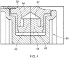
- Figure 4 shows a bearing arrangement 66 that is an alternative embodiment to the Figure 3 example, in which the second bush 62 comprises a third bush portion 65 that engages a shaft 64.
- the third portion bush 65 is positioned between the inside of the recess 67 and the second bush 62.
- the second bush 62 comprises a main section 68 and a stem 66.
- the radius of the stem 66 is less than the radius of the recess 67.
- the third bush portion 65 is then positioned between the stem 66 and the recess 67.
- the third bush portion is arranged across a contact area between the stem and the recess of the shaft.
- the contact area may be the axially extending (with respect to the central axis 41) contact area between stem 56 and the recess 47.
- the third bush portion 65 is annular and cylindrical. There is a radial step between the stem 66 and the main section 68 to accommodate the widths of the third bush portion 65 and the section of the shaft 64 around the recess 67.
- the recess 67 has a conical end at its deepest portion.
- the recess 67 may be flat at its deepest portion, as in the figure 3 example.
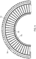
- FIG. 5 shows an arrangement of a plurality of variable stator vanes (VSVs) 72 arranged between an outer casing 78 and an inner shroud 76. Between each VSV 72 and the inner shroud 76 are located a bearing arrangement 74 as described and/or claimed herein.
- VSVs variable stator vanes
- the inner shroud 76 contains a number of bearing housings equal to the number of VSVs 72. Each bearing housing may be as described and/or claimed herein, for example as shown by the example of figure 3 or figure 4 .
- the bearing housings are blind holes, that is to say that they are only open at one end.
- the inner shroud 76 is a split ring inner shroud, and in figure 5 extends around half of the circumference.
- the set of VSVs 72 may be assembled into the arrangement shown in figure 5 using following method. Firstly the VSVs 72 are located within the outer casing 78. The top end, i.e. the radially outer end in use, of each VSV 72 is received by features of the outer casing 78, for example a bearing. The inner shroud 76 is then introduced radially. For example the inner shroud 76 is introduced from a position radially inward of the set of VSVs 72 that are assembled around at least a part of the circumference of the outer casing 78. This requires that the inner shroud 76 is pulled in on its own radius, positioned inboard of the set of VSVs 72, and then allowed to expand on its own radius again.
- Tooling may be required to compress the inner shroud 56 due to the stiffness of the inner shroud 76.
- each of the shafts (equivalent to shaft 44 of figure 3 ) of the VSVs 72 engage into the plurality of bearings 74.
- Each bearing 74 of the inner shroud 76 has a second bush (for example the second bush 42 of figure 3 ) already inserted into it before the inner shroud 76 is allowed to expand on radius again.
- the shafts of each VSV are inserted into the bearing housings 74 they will engage with the second bushes. For example they will engage in the manner of the arrangement shown in the figure 3 or figure 4 example.
- Figure 5 only shows half of the circumference of the gas turbine.
- the arrangement shown in figure 5 may extend around the entire circumference of the gas turbine.
- the inner shroud 76 of figure 5 is a split ring inner shroud that only extends around half of the gas turbine. Therefore in the arrangement shown in figure 5 there will be a second inner shroud (not shown) for the opposing side of the set of VSVs (also not shown) in order to complete the circumferential arrangement.
- the second inner shroud will be assembled into the circumference in the same manner as the inner shroud 76 shown in figure 5 .
- there may be more split ring inner shrouds For example there may be 3, 4, 5, 6 or more than 6 inner shrouds completing the circumference.
- the bearing length can be increased whilst minimising the amount the inner shrouds need to be pulled inwards in order to assemble them into the arrangement shown in the figure 5 example.
Landscapes
- Engineering & Computer Science (AREA)
- General Engineering & Computer Science (AREA)
- Mechanical Engineering (AREA)
- Structures Of Non-Positive Displacement Pumps (AREA)
- Support Of The Bearing (AREA)
Claims (12)
- Lageranordnung (36, 66, 74) für variable Leitschaufeln für eine Gasturbinentriebwerk, wobei die Lageranordnung folgendes umfasst:eine Welle (44, 64) mit einer Aussparung (47, 67) in deren Ende;ein Lagergehäuse (46, 76);eine ringförmige erste Buchse (40), die einen inneren ersten Teil (52) und einen inneren zweiten Teil (54) umfasst; wobei die Lageranordnung dadurch gekennzeichnet ist, dass sie ferner folgendes umfasst:eine zweite Buchse (42, 62), die mit der Aussparung der Welle eingreift;
wobeidie erste Buchse an dem Lagergehäuse lagert;die Welle mit dem inneren ersten Teil der ersten Buchse eingreift; unddie zweite Buchse mit dem inneren zweiten Teil der ersten Buchse eingreift. - Lageranordnung nach Anspruch 1, wobei:die zweite Buchse einen Hauptabschnitt (58, 68) und einen Schaft (56, 66) umfasst, der sich von dem Hauptabschnitt erstreckt, wobei der Schaft dünner ist als der Hauptabschnitt;der Schaft mit der Aussparung der Welle eingreift; und wobeisich der Hauptabschnitt in Kontakt mit dem inneren zweiten Teil der ersten Buchse befindet.
- Lageranordnung nach Anspruch 1, wobei:die zweite Buchse einen Hauptabschnitt (58, 68) und einen Schaft (56, 66) umfasst, der sich von dem Hauptabschnitt erstreckt, wobei der Schaft dünner ist als der Hauptabschnitt;die zweite Buchse ferner einen ringförmigen dritten Buchsenteil (65) umfasst, wobei der dritte Buchsenteil zwischen dem Schaft und der Aussparung der Welle positioniert ist, so dass er mit der Aussparung der Welle eingreift; und wobeisich der Hauptabschnitt in Kontakt mit dem inneren zweiten Teil der ersten Buchse befindet.
- Lageranordnung nach einem der vorstehenden Ansprüche, wobei:
das Lagergehäuse aus einem Blindloch in einer festen Komponente gebildet wird. - Lagereinheit, welche die Lageranordnung nach einem der vorstehenden Ansprüche umfasst, wobei die Lagereinheit ferner eine drehbare Komponente (34) umfasst, wobei:sich die Welle von der drehbaren Komponente erstreckt; und wobeidie drehbare Komponente eine variable Leitschaufel eines Gasturbinentriebwerks ist.
- Lagereinheit nach Anspruch 5, wobei:
das Lagergehäuse in einer inneren Ummantelung eines Gasturbinentriebwerks (20) ausgebildet ist. - Anordnung variabler Leitschaufeln für ein Gasturbinentriebwerk, wobei die Anordnung variabler Leitschaufeln folgendes umfasst:eine Mehrzahl von Lagereinheiten nach Anspruch 5; undeine innere Ummantelung eines Gasturbinentriebwerks, wobei:jedes Lagergehäuse in der inneren Ummantelung ausgebildet ist; und wobeidie Lagergehäuse um die innere Ummantelung gleichmäßig beabstandet angeordnet sind.
- Anordnung variabler Leitschaufeln nach Anspruch 7, wobei:
die innere Ummantelung eine innere Ummantelung mit Spaltring ist, die sich nur teilweise um den Umfang des Gasturbinentriebwerks erstreckt. - Gasturbinentriebwerk, welches die Anordnung variabler Leitschaufeln nach Anspruch 7 oder 8 umfasst.
- Verfahren zur Herstellung einer Anordnung variabler Leitschaufeln nach Anspruch 8, wobei die Vorrichtung ferner ein äußeres Gehäuse (78) eines Gasturbinentriebwerks umfasst, wobei das Verfahren folgendes umfasst:Montieren einer Mehrzahl variabler Leitschaufeln in das äußere Gehäuse, so dass sie von dem äußeren Gehäuse um den Umfang des äußeren Gehäuses radial einwärts vorstehen;Platzieren der ersten Buchse und der zweiten Buchse jeweils in deren entsprechenden Lagergehäuse;Komprimieren der inneren Ummantelung, so dass sich deren Radius verringert;Positionieren der inneren Ummantelung radial einwärts der montierten variablen Leitschaufeln;Lösen der Komprimierung an der inneren Ummantelung, so dass diese wieder ihren ursprünglichen Radius annehmen kann, und wobei dabei die Welle jeder variablen Leitschaufel in jedes entsprechende Lagergehäuse an der inneren Ummantelung eingeführt wird.
- Verfahren nach Anspruch 10, wobei:
die innere Ummantelung eine Mehrzahl innerer Ummantelungssegmente umfasst, wobei sich jedes innere Ummantelungssegment nur teilweise um den Umfang erstreckt, und wobei das Verfahren nach Anspruch 10 sequentiell auf jedes innere Ummantelungssegment angewendet wird. - Verfahren nach Anspruch 11, wobei
sich jedes innere Ummantelungssegment um 180 Grad erstreckt.
Applications Claiming Priority (1)
| Application Number | Priority Date | Filing Date | Title |
|---|---|---|---|
| GBGB1715165.5A GB201715165D0 (en) | 2017-09-20 | 2017-09-20 | Bearing assembly |
Publications (2)
| Publication Number | Publication Date |
|---|---|
| EP3460196A1 EP3460196A1 (de) | 2019-03-27 |
| EP3460196B1 true EP3460196B1 (de) | 2020-11-25 |
Family
ID=60159614
Family Applications (1)
| Application Number | Title | Priority Date | Filing Date |
|---|---|---|---|
| EP18189680.4A Active EP3460196B1 (de) | 2017-09-20 | 2018-08-20 | Lageranordnung für eine variable leitschaufel |
Country Status (3)
| Country | Link |
|---|---|
| US (1) | US10753393B2 (de) |
| EP (1) | EP3460196B1 (de) |
| GB (1) | GB201715165D0 (de) |
Family Cites Families (9)
| Publication number | Priority date | Publication date | Assignee | Title |
|---|---|---|---|---|
| US3887976A (en) | 1971-02-03 | 1975-06-10 | J Rodger Sheilds | Stator blade assembly for turbo machines |
| FR2524934B1 (fr) | 1982-04-08 | 1986-12-26 | Snecma | Dispositif de butee de securite pour pivot d'aubes de stator a calage variable |
| FR2556410B1 (fr) * | 1983-12-07 | 1986-09-12 | Snecma | Dispositif de centrage de l'anneau interieur d'un stator a ailettes a calage variable |
| US5593275A (en) * | 1995-08-01 | 1997-01-14 | General Electric Company | Variable stator vane mounting and vane actuation system for an axial flow compressor of a gas turbine engine |
| US6086327A (en) | 1999-01-20 | 2000-07-11 | Mack Plastics Corporation | Bushing for a jet engine vane |
| US9410443B2 (en) * | 2012-01-27 | 2016-08-09 | United Technologies Corporation | Variable vane damping assembly |
| EP2716874B1 (de) * | 2012-10-08 | 2017-12-27 | MTU Aero Engines AG | Leitschaufelkranz, Montageverfahren und Strömungsmaschine |
| US9341194B2 (en) * | 2012-11-01 | 2016-05-17 | Solar Turbines Incorporated | Gas turbine engine compressor with a biased inner ring |
| US9932988B2 (en) * | 2013-02-15 | 2018-04-03 | United Technologies Corporation | Bushing arranged between a body and a shaft, and connected to the shaft |
-
2017
- 2017-09-20 GB GBGB1715165.5A patent/GB201715165D0/en not_active Ceased
-
2018
- 2018-08-20 EP EP18189680.4A patent/EP3460196B1/de active Active
- 2018-08-21 US US16/106,950 patent/US10753393B2/en active Active
Non-Patent Citations (1)
| Title |
|---|
| None * |
Also Published As
| Publication number | Publication date |
|---|---|
| US10753393B2 (en) | 2020-08-25 |
| US20190085903A1 (en) | 2019-03-21 |
| GB201715165D0 (en) | 2017-11-01 |
| EP3460196A1 (de) | 2019-03-27 |
Similar Documents
| Publication | Publication Date | Title |
|---|---|---|
| US11022145B2 (en) | Bushing arranged between a body and a shaft, and connected to the shaft | |
| EP2971693B1 (de) | Scheibendichtungsanordnung für einen gasturbinenmotorrotor | |
| US11371380B2 (en) | Variable guide vane assembly and vane arms therefor | |
| US10337621B2 (en) | Hydrostatic non-contact seal with weight reduction pocket | |
| CN107044346B (zh) | 高负载事件期间的轴承外座圈固位 | |
| EP1431521A2 (de) | Verfahren und Vorrichtung zur Dichtung von verstellbaren Leitschaufeln einer Gasturbine | |
| EP4006314B1 (de) | Gasturbinentriebwerk | |
| JP2017008938A (ja) | タービンエンジン用のトラニオン保持 | |
| CN108374721B (zh) | 转子推力平衡的涡轮发动机 | |
| EP4001596B1 (de) | Gasturbinentriebwerk | |
| US20180058235A1 (en) | Axial flow machine | |
| US9856740B2 (en) | Tip-controlled integrally bladed rotor for gas turbine engine | |
| EP3800378B1 (de) | Versteifungselement für die gehäuseanordnung eines planetengetriebes | |
| CN112443364A (zh) | 用于同心可变定子静叶的促动组件 | |
| EP3460196B1 (de) | Lageranordnung für eine variable leitschaufel | |
| EP3647541B1 (de) | Vernier-spaltring für turbinenrotorstapelanordnung | |
| CN114962002A (zh) | 带有弹性支撑的轴承组件及航空发动机 | |
| EP4039943B1 (de) | Gasturbinentriebwerk | |
| EP3800373B1 (de) | Gehäuseanordnung eines planetengetriebesystems | |
| EP3800366A1 (de) | Lagerfeder für die gehäuseanordnung eines planetengetriebesystems | |
| CN114026332B (zh) | 用于涡轮发动机的压缩机外壳 | |
| US20210277799A1 (en) | Bearing support structure with variable stiffness |
Legal Events
| Date | Code | Title | Description |
|---|---|---|---|
| PUAI | Public reference made under article 153(3) epc to a published international application that has entered the european phase |
Free format text: ORIGINAL CODE: 0009012 |
|
| STAA | Information on the status of an ep patent application or granted ep patent |
Free format text: STATUS: THE APPLICATION HAS BEEN PUBLISHED |
|
| AK | Designated contracting states |
Kind code of ref document: A1 Designated state(s): AL AT BE BG CH CY CZ DE DK EE ES FI FR GB GR HR HU IE IS IT LI LT LU LV MC MK MT NL NO PL PT RO RS SE SI SK SM TR |
|
| AX | Request for extension of the european patent |
Extension state: BA ME |
|
| STAA | Information on the status of an ep patent application or granted ep patent |
Free format text: STATUS: REQUEST FOR EXAMINATION WAS MADE |
|
| 17P | Request for examination filed |
Effective date: 20190923 |
|
| RBV | Designated contracting states (corrected) |
Designated state(s): AL AT BE BG CH CY CZ DE DK EE ES FI FR GB GR HR HU IE IS IT LI LT LU LV MC MK MT NL NO PL PT RO RS SE SI SK SM TR |
|
| RAP1 | Party data changed (applicant data changed or rights of an application transferred) |
Owner name: ROLLS-ROYCE PLC |
|
| STAA | Information on the status of an ep patent application or granted ep patent |
Free format text: STATUS: EXAMINATION IS IN PROGRESS |
|
| 17Q | First examination report despatched |
Effective date: 20200311 |
|
| RIC1 | Information provided on ipc code assigned before grant |
Ipc: F16C 17/02 20060101ALI20200610BHEP Ipc: F01D 17/16 20060101AFI20200610BHEP Ipc: F16C 35/02 20060101ALN20200610BHEP |
|
| GRAP | Despatch of communication of intention to grant a patent |
Free format text: ORIGINAL CODE: EPIDOSNIGR1 |
|
| STAA | Information on the status of an ep patent application or granted ep patent |
Free format text: STATUS: GRANT OF PATENT IS INTENDED |
|
| RIC1 | Information provided on ipc code assigned before grant |
Ipc: F01D 17/16 20060101AFI20200630BHEP Ipc: F16C 35/02 20060101ALN20200630BHEP Ipc: F16C 17/02 20060101ALI20200630BHEP |
|
| INTG | Intention to grant announced |
Effective date: 20200723 |
|
| GRAS | Grant fee paid |
Free format text: ORIGINAL CODE: EPIDOSNIGR3 |
|
| GRAA | (expected) grant |
Free format text: ORIGINAL CODE: 0009210 |
|
| STAA | Information on the status of an ep patent application or granted ep patent |
Free format text: STATUS: THE PATENT HAS BEEN GRANTED |
|
| AK | Designated contracting states |
Kind code of ref document: B1 Designated state(s): AL AT BE BG CH CY CZ DE DK EE ES FI FR GB GR HR HU IE IS IT LI LT LU LV MC MK MT NL NO PL PT RO RS SE SI SK SM TR |
|
| REG | Reference to a national code |
Ref country code: GB Ref legal event code: FG4D |
|
| REG | Reference to a national code |
Ref country code: CH Ref legal event code: EP |
|
| REG | Reference to a national code |
Ref country code: AT Ref legal event code: REF Ref document number: 1338547 Country of ref document: AT Kind code of ref document: T Effective date: 20201215 |
|
| REG | Reference to a national code |
Ref country code: DE Ref legal event code: R096 Ref document number: 602018010051 Country of ref document: DE |
|
| REG | Reference to a national code |
Ref country code: IE Ref legal event code: FG4D |
|
| REG | Reference to a national code |
Ref country code: AT Ref legal event code: MK05 Ref document number: 1338547 Country of ref document: AT Kind code of ref document: T Effective date: 20201125 |
|
| REG | Reference to a national code |
Ref country code: NL Ref legal event code: MP Effective date: 20201125 |
|
| PG25 | Lapsed in a contracting state [announced via postgrant information from national office to epo] |
Ref country code: NO Free format text: LAPSE BECAUSE OF FAILURE TO SUBMIT A TRANSLATION OF THE DESCRIPTION OR TO PAY THE FEE WITHIN THE PRESCRIBED TIME-LIMIT Effective date: 20210225 Ref country code: GR Free format text: LAPSE BECAUSE OF FAILURE TO SUBMIT A TRANSLATION OF THE DESCRIPTION OR TO PAY THE FEE WITHIN THE PRESCRIBED TIME-LIMIT Effective date: 20210226 Ref country code: PT Free format text: LAPSE BECAUSE OF FAILURE TO SUBMIT A TRANSLATION OF THE DESCRIPTION OR TO PAY THE FEE WITHIN THE PRESCRIBED TIME-LIMIT Effective date: 20210325 Ref country code: RS Free format text: LAPSE BECAUSE OF FAILURE TO SUBMIT A TRANSLATION OF THE DESCRIPTION OR TO PAY THE FEE WITHIN THE PRESCRIBED TIME-LIMIT Effective date: 20201125 Ref country code: FI Free format text: LAPSE BECAUSE OF FAILURE TO SUBMIT A TRANSLATION OF THE DESCRIPTION OR TO PAY THE FEE WITHIN THE PRESCRIBED TIME-LIMIT Effective date: 20201125 |
|
| PG25 | Lapsed in a contracting state [announced via postgrant information from national office to epo] |
Ref country code: SE Free format text: LAPSE BECAUSE OF FAILURE TO SUBMIT A TRANSLATION OF THE DESCRIPTION OR TO PAY THE FEE WITHIN THE PRESCRIBED TIME-LIMIT Effective date: 20201125 Ref country code: LV Free format text: LAPSE BECAUSE OF FAILURE TO SUBMIT A TRANSLATION OF THE DESCRIPTION OR TO PAY THE FEE WITHIN THE PRESCRIBED TIME-LIMIT Effective date: 20201125 Ref country code: IS Free format text: LAPSE BECAUSE OF FAILURE TO SUBMIT A TRANSLATION OF THE DESCRIPTION OR TO PAY THE FEE WITHIN THE PRESCRIBED TIME-LIMIT Effective date: 20210325 Ref country code: PL Free format text: LAPSE BECAUSE OF FAILURE TO SUBMIT A TRANSLATION OF THE DESCRIPTION OR TO PAY THE FEE WITHIN THE PRESCRIBED TIME-LIMIT Effective date: 20201125 Ref country code: BG Free format text: LAPSE BECAUSE OF FAILURE TO SUBMIT A TRANSLATION OF THE DESCRIPTION OR TO PAY THE FEE WITHIN THE PRESCRIBED TIME-LIMIT Effective date: 20210225 Ref country code: AT Free format text: LAPSE BECAUSE OF FAILURE TO SUBMIT A TRANSLATION OF THE DESCRIPTION OR TO PAY THE FEE WITHIN THE PRESCRIBED TIME-LIMIT Effective date: 20201125 |
|
| REG | Reference to a national code |
Ref country code: LT Ref legal event code: MG9D |
|
| PG25 | Lapsed in a contracting state [announced via postgrant information from national office to epo] |
Ref country code: HR Free format text: LAPSE BECAUSE OF FAILURE TO SUBMIT A TRANSLATION OF THE DESCRIPTION OR TO PAY THE FEE WITHIN THE PRESCRIBED TIME-LIMIT Effective date: 20201125 |
|
| PG25 | Lapsed in a contracting state [announced via postgrant information from national office to epo] |
Ref country code: CZ Free format text: LAPSE BECAUSE OF FAILURE TO SUBMIT A TRANSLATION OF THE DESCRIPTION OR TO PAY THE FEE WITHIN THE PRESCRIBED TIME-LIMIT Effective date: 20201125 Ref country code: EE Free format text: LAPSE BECAUSE OF FAILURE TO SUBMIT A TRANSLATION OF THE DESCRIPTION OR TO PAY THE FEE WITHIN THE PRESCRIBED TIME-LIMIT Effective date: 20201125 Ref country code: SM Free format text: LAPSE BECAUSE OF FAILURE TO SUBMIT A TRANSLATION OF THE DESCRIPTION OR TO PAY THE FEE WITHIN THE PRESCRIBED TIME-LIMIT Effective date: 20201125 Ref country code: SK Free format text: LAPSE BECAUSE OF FAILURE TO SUBMIT A TRANSLATION OF THE DESCRIPTION OR TO PAY THE FEE WITHIN THE PRESCRIBED TIME-LIMIT Effective date: 20201125 Ref country code: RO Free format text: LAPSE BECAUSE OF FAILURE TO SUBMIT A TRANSLATION OF THE DESCRIPTION OR TO PAY THE FEE WITHIN THE PRESCRIBED TIME-LIMIT Effective date: 20201125 Ref country code: LT Free format text: LAPSE BECAUSE OF FAILURE TO SUBMIT A TRANSLATION OF THE DESCRIPTION OR TO PAY THE FEE WITHIN THE PRESCRIBED TIME-LIMIT Effective date: 20201125 |
|
| REG | Reference to a national code |
Ref country code: DE Ref legal event code: R097 Ref document number: 602018010051 Country of ref document: DE |
|
| PG25 | Lapsed in a contracting state [announced via postgrant information from national office to epo] |
Ref country code: DK Free format text: LAPSE BECAUSE OF FAILURE TO SUBMIT A TRANSLATION OF THE DESCRIPTION OR TO PAY THE FEE WITHIN THE PRESCRIBED TIME-LIMIT Effective date: 20201125 |
|
| PLBE | No opposition filed within time limit |
Free format text: ORIGINAL CODE: 0009261 |
|
| STAA | Information on the status of an ep patent application or granted ep patent |
Free format text: STATUS: NO OPPOSITION FILED WITHIN TIME LIMIT |
|
| PG25 | Lapsed in a contracting state [announced via postgrant information from national office to epo] |
Ref country code: IT Free format text: LAPSE BECAUSE OF FAILURE TO SUBMIT A TRANSLATION OF THE DESCRIPTION OR TO PAY THE FEE WITHIN THE PRESCRIBED TIME-LIMIT Effective date: 20201125 Ref country code: NL Free format text: LAPSE BECAUSE OF FAILURE TO SUBMIT A TRANSLATION OF THE DESCRIPTION OR TO PAY THE FEE WITHIN THE PRESCRIBED TIME-LIMIT Effective date: 20201125 Ref country code: AL Free format text: LAPSE BECAUSE OF FAILURE TO SUBMIT A TRANSLATION OF THE DESCRIPTION OR TO PAY THE FEE WITHIN THE PRESCRIBED TIME-LIMIT Effective date: 20201125 |
|
| 26N | No opposition filed |
Effective date: 20210826 |
|
| PG25 | Lapsed in a contracting state [announced via postgrant information from national office to epo] |
Ref country code: SI Free format text: LAPSE BECAUSE OF FAILURE TO SUBMIT A TRANSLATION OF THE DESCRIPTION OR TO PAY THE FEE WITHIN THE PRESCRIBED TIME-LIMIT Effective date: 20201125 |
|
| PG25 | Lapsed in a contracting state [announced via postgrant information from national office to epo] |
Ref country code: ES Free format text: LAPSE BECAUSE OF FAILURE TO SUBMIT A TRANSLATION OF THE DESCRIPTION OR TO PAY THE FEE WITHIN THE PRESCRIBED TIME-LIMIT Effective date: 20201125 |
|
| REG | Reference to a national code |
Ref country code: CH Ref legal event code: PL |
|
| PG25 | Lapsed in a contracting state [announced via postgrant information from national office to epo] |
Ref country code: MC Free format text: LAPSE BECAUSE OF FAILURE TO SUBMIT A TRANSLATION OF THE DESCRIPTION OR TO PAY THE FEE WITHIN THE PRESCRIBED TIME-LIMIT Effective date: 20201125 |
|
| REG | Reference to a national code |
Ref country code: BE Ref legal event code: MM Effective date: 20210831 |
|
| PG25 | Lapsed in a contracting state [announced via postgrant information from national office to epo] |
Ref country code: LI Free format text: LAPSE BECAUSE OF NON-PAYMENT OF DUE FEES Effective date: 20210831 Ref country code: CH Free format text: LAPSE BECAUSE OF NON-PAYMENT OF DUE FEES Effective date: 20210831 |
|
| PG25 | Lapsed in a contracting state [announced via postgrant information from national office to epo] |
Ref country code: IS Free format text: LAPSE BECAUSE OF FAILURE TO SUBMIT A TRANSLATION OF THE DESCRIPTION OR TO PAY THE FEE WITHIN THE PRESCRIBED TIME-LIMIT Effective date: 20210325 Ref country code: LU Free format text: LAPSE BECAUSE OF NON-PAYMENT OF DUE FEES Effective date: 20210820 |
|
| PG25 | Lapsed in a contracting state [announced via postgrant information from national office to epo] |
Ref country code: IE Free format text: LAPSE BECAUSE OF NON-PAYMENT OF DUE FEES Effective date: 20210820 Ref country code: BE Free format text: LAPSE BECAUSE OF NON-PAYMENT OF DUE FEES Effective date: 20210831 |
|
| PG25 | Lapsed in a contracting state [announced via postgrant information from national office to epo] |
Ref country code: CY Free format text: LAPSE BECAUSE OF FAILURE TO SUBMIT A TRANSLATION OF THE DESCRIPTION OR TO PAY THE FEE WITHIN THE PRESCRIBED TIME-LIMIT Effective date: 20201125 |
|
| P01 | Opt-out of the competence of the unified patent court (upc) registered |
Effective date: 20230528 |
|
| PG25 | Lapsed in a contracting state [announced via postgrant information from national office to epo] |
Ref country code: HU Free format text: LAPSE BECAUSE OF FAILURE TO SUBMIT A TRANSLATION OF THE DESCRIPTION OR TO PAY THE FEE WITHIN THE PRESCRIBED TIME-LIMIT; INVALID AB INITIO Effective date: 20180820 |
|
| PGFP | Annual fee paid to national office [announced via postgrant information from national office to epo] |
Ref country code: GB Payment date: 20230822 Year of fee payment: 6 |
|
| PGFP | Annual fee paid to national office [announced via postgrant information from national office to epo] |
Ref country code: FR Payment date: 20230824 Year of fee payment: 6 Ref country code: DE Payment date: 20230828 Year of fee payment: 6 |
|
| PG25 | Lapsed in a contracting state [announced via postgrant information from national office to epo] |
Ref country code: MK Free format text: LAPSE BECAUSE OF FAILURE TO SUBMIT A TRANSLATION OF THE DESCRIPTION OR TO PAY THE FEE WITHIN THE PRESCRIBED TIME-LIMIT Effective date: 20201125 |