EP3460096A1 - Sliding member for compressor - Google Patents
Sliding member for compressor Download PDFInfo
- Publication number
- EP3460096A1 EP3460096A1 EP18196195.4A EP18196195A EP3460096A1 EP 3460096 A1 EP3460096 A1 EP 3460096A1 EP 18196195 A EP18196195 A EP 18196195A EP 3460096 A1 EP3460096 A1 EP 3460096A1
- Authority
- EP
- European Patent Office
- Prior art keywords
- plating layer
- mass
- electroless nickel
- nickel plating
- sliding member
- Prior art date
- Legal status (The legal status is an assumption and is not a legal conclusion. Google has not performed a legal analysis and makes no representation as to the accuracy of the status listed.)
- Pending
Links
Images



Classifications
-
- C—CHEMISTRY; METALLURGY
- C23—COATING METALLIC MATERIAL; COATING MATERIAL WITH METALLIC MATERIAL; CHEMICAL SURFACE TREATMENT; DIFFUSION TREATMENT OF METALLIC MATERIAL; COATING BY VACUUM EVAPORATION, BY SPUTTERING, BY ION IMPLANTATION OR BY CHEMICAL VAPOUR DEPOSITION, IN GENERAL; INHIBITING CORROSION OF METALLIC MATERIAL OR INCRUSTATION IN GENERAL
- C23C—COATING METALLIC MATERIAL; COATING MATERIAL WITH METALLIC MATERIAL; SURFACE TREATMENT OF METALLIC MATERIAL BY DIFFUSION INTO THE SURFACE, BY CHEMICAL CONVERSION OR SUBSTITUTION; COATING BY VACUUM EVAPORATION, BY SPUTTERING, BY ION IMPLANTATION OR BY CHEMICAL VAPOUR DEPOSITION, IN GENERAL
- C23C18/00—Chemical coating by decomposition of either liquid compounds or solutions of the coating forming compounds, without leaving reaction products of surface material in the coating; Contact plating
- C23C18/16—Chemical coating by decomposition of either liquid compounds or solutions of the coating forming compounds, without leaving reaction products of surface material in the coating; Contact plating by reduction or substitution, e.g. electroless plating
- C23C18/1601—Process or apparatus
- C23C18/1633—Process of electroless plating
- C23C18/1646—Characteristics of the product obtained
- C23C18/165—Multilayered product
- C23C18/1651—Two or more layers only obtained by electroless plating
-
- C—CHEMISTRY; METALLURGY
- C23—COATING METALLIC MATERIAL; COATING MATERIAL WITH METALLIC MATERIAL; CHEMICAL SURFACE TREATMENT; DIFFUSION TREATMENT OF METALLIC MATERIAL; COATING BY VACUUM EVAPORATION, BY SPUTTERING, BY ION IMPLANTATION OR BY CHEMICAL VAPOUR DEPOSITION, IN GENERAL; INHIBITING CORROSION OF METALLIC MATERIAL OR INCRUSTATION IN GENERAL
- C23C—COATING METALLIC MATERIAL; COATING MATERIAL WITH METALLIC MATERIAL; SURFACE TREATMENT OF METALLIC MATERIAL BY DIFFUSION INTO THE SURFACE, BY CHEMICAL CONVERSION OR SUBSTITUTION; COATING BY VACUUM EVAPORATION, BY SPUTTERING, BY ION IMPLANTATION OR BY CHEMICAL VAPOUR DEPOSITION, IN GENERAL
- C23C18/00—Chemical coating by decomposition of either liquid compounds or solutions of the coating forming compounds, without leaving reaction products of surface material in the coating; Contact plating
- C23C18/16—Chemical coating by decomposition of either liquid compounds or solutions of the coating forming compounds, without leaving reaction products of surface material in the coating; Contact plating by reduction or substitution, e.g. electroless plating
- C23C18/31—Coating with metals
- C23C18/32—Coating with nickel, cobalt or mixtures thereof with phosphorus or boron
- C23C18/34—Coating with nickel, cobalt or mixtures thereof with phosphorus or boron using reducing agents
- C23C18/36—Coating with nickel, cobalt or mixtures thereof with phosphorus or boron using reducing agents using hypophosphites
Definitions
- the present disclosure relates to a sliding member of a compressor such as a vane compressor of an air conditioner for a motor vehicle, and applies low-phosphorus nickel plating to the sliding member for the purpose of reducing the cost of the sliding member such as a vane.
- a vane compressor for example, includes a cam ring, a rotor which is rotatably accommodated in the cam ring and is fixed to a drive shaft, vanes which are inserted into a plurality of vane grooves provided at the rotor, a front side member which is fixed to one end surface of the cam ring, and a rear side member which is fixed to the other end surface of the cam ring.
- the drive shaft is rotatably supported by the front side member and the rear side member via bearings.
- a suction port for a working fluid (refrigerant gas) and a suction chamber (a low-pressure chamber) communicating with the suction port are formed in the front side member, and a discharge port for the working fluid and a discharge chamber
- Ni-P-B plating blended with boron is used as described in a technique of Patent Literature 2 or Patent Literature 3, or for example, Ni-Co-P plating blended with cobalt is used as described in a technique of Patent Literature 4.
- these plating is expensive.
- Ni particles might adhere to a surface of a plated vane and a post-process for removing the Ni particles is required, which increases the cost.
- an object of the present disclosure is to provide a sliding member for a compressor whose sliding portion is applied with a plating film, in which both the hardness and toughness of the plating film are good, adhesion of the Ni particles is inhibited, and the plating film is inexpensive.
- an electroless low-phosphorus nickel plating layer which is a non-heat treated layer and contains Ni crystallites having a crystallite diameter of 8 nm to 11 nm provides both good hardness and toughness of a plating film and solved the problem of the present invention.
- a sliding member for a compressor is a sliding member for a compressor including a base material formed of an aluminum alloy, and an electroless nickel plating layer containing phosphorus which is formed on a surface of the base material, in which in the electroless nickel plating layer, a phosphorus (P) content is equal to or more than 1.0 mass% and equal to or less than 2.0 mass%, a boron (B) content is equal to or more than 0 mass% and equal to or less than 0.01 mass%, and a cobalt (Co) content is equal to or more than 0 mass% and equal to or less than 0.01 mass%, the electroless nickel plating layer is a non-heat treated layer, the electroless nickel plating layer contains Ni crystallites, and a crystallite diameter of the Ni crystallites measured by an X-ray diffraction method is 8 nm to 11 nm.
- a Vickers hardness of the electroless nickel plating layer is preferably equal to or more than 650 Hv and equal to or less than 750 Hv.
- the electroless nickel plating layer preferably does not contain boron (B) and cobalt (Co). According to the present configuration, a plating solution to be used can be made inexpensive.
- the electroless nickel plating layer is preferably a barrel plating layer. According to the present configuration, Ni particles are prevented from accumulating, and smoothness of the member increases.
- the sliding member for a compressor according to the present invention has an underlayer between the base material and the electroless nickel plating layer, and the underlayer is an electroless nickel plating layer containing 6.0 mass% to 11.0 mass% of phosphorus (P) and a non-heat treated layer.
- the underlayer is a medium phosphorus type plating layer, adhesion with the base material is good, and smoothness increases.
- the underlayer preferably does not contain boron (B) and cobalt (Co). According to the present configuration, a plating solution to be used can be made inexpensive.
- a film thickness of the electroless nickel plating layer formed on the surface of the base material or a total thickness of the underlayer formed on the surface of the base material and the electroless nickel plating layer is preferably 15 ⁇ m to 30 pm. According to the present configuration, the film thickness of the plating film is optimal to a vane to be used.
- the electroless nickel plating layer is preferably a non-dispersion plating film where ceramic particulates do not disperse in the layer.
- the hardness and scratch strength of the plating film can be improved.
- the sliding member for a compressor whose sliding portion is applied with the plating film can be provided, in which both the hardness and toughness of the plating film are satisfied, adhesion of Ni particles is inhibited, and the plating film is inexpensive.
- Compressors include a vane compressor, a swash plate compressor and the like.
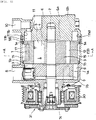
- Fig. 4 and Fig. 5 illustrate a configuration of the vane compressor as an example.
- the vane compressor includes a cam ring 1, a rotor 3 which is rotatably accommodated in the cam ring and is fixed to a drive shaft 2, vanes 5 which are inserted into a plurality of vane grooves 4 provided at the rotor 3, a rear side member 6 which is fixed to a rear side end surface of the cam ring 1, and a shell member 7 which surrounds a front side end surface and an outer circumferential surface of the cam ring 1 and is fitted to the rear side member 6.
- the drive shaft 2 is rotatably supported by the shell member 7 and the rear side member 6 via bearings.
- a suction port 8 for a working fluid (refrigerant gas) and a suction chamber (a low-pressure chamber) 9 communicating with the suction port 8 are formed in the shell member 7, and a discharge port 10 for the working fluid and a discharge chamber (a high-pressure chamber) 11 communicating with the discharge port 10 are formed in the rear side member 6.
- a compression space 12 is defined between an inner circumferential surface of the cam ring 1 and an outer circumferential surface of the rotor 3.
- the compression space 12 is divided by the vanes 5 to form a plurality of compression chambers 13, and a capacity of each compression chamber varies according to rotation of the rotor 3.
- a base material of the vane 5 is formed from a material containing aluminum as a main component for the purpose of weight reduction or the like
- a plating film is formed on surfaces of the base material of the vane 5
- the cam ring 1, the rear side member 6, the shell member 7, the rotor 3 and the like of the vane compressor can also be considered as sliding members, and the plating film may be formed on the surfaces thereof, so that the requirements of the hardness and abrasion resistance can also be satisfied.
- a plating film is formed in a portion where members are in slide contact with each other, so that the requirements of the hardness and abrasion resistance can also be satisfied.
- a material of the sliding member is, for example, an aluminum-based alloy.
- the aluminum-based alloy include an aluminum-based alloy such as 2000 series, 4000 series, 5000 series, 6000 series and 7000 series, and an aluminum alloy having a high silicon content such as ADC10, ADC12, ADC14 and A390.
- the material of the sliding member is preferably an aluminum-based alloy.
- the sliding member for a compressor where the plating film (also called plating layer) is formed will be described.
- an electroless nickel plating layer is formed on at least a sliding portion. That is, the sliding member for a compressor according to the present embodiment is a sliding member for a compressor including a base material formed of an aluminum alloy, and an electroless nickel plating layer containing phosphorus which is formed on a surface of the base material, in which in the electroless nickel plating layer, a phosphorus (P) content is equal to or more than 1.0 mass% and equal to or less than 2.0 mass%, a boron (B) content is equal to or more than 0 mass% and equal to or less than 0.01 mass%, and a cobalt (Co) content is equal to or more than 0 mass% and equal to or less than 0.01 mass%, the electroless nickel plating layer is a non-heat treated layer and contains Ni crystallites, and a crystallite diameter of the crystallites measured by
- the plating film is deposited and formed by using an electroless plating bath which contains a nickel salt such as nickel sulfate and nickel chloride as a supply source of nickel ions, and a phosphorus compound such as sodium hypophosphite as a reducing agent.
- a ratio of the nickel salt to the phosphorus compound in the plating bath is appropriately adjusted in accordance with a composition of the plating film.
- a stabilizer for preventing decomposition of a plating solution and inhibiting plating deposition, a pH adjuster such as sodium hydroxide and aqueous ammonia, a complexing agent containing an organic acid such as sodium acetate and sodium citrate, and a buffer such as sodium citrate can be added into the plating bath.
- the plating film can be formed by immersing a surface to be plated of the base material in the plating bath for constant time.
- a temperature of the plating bath is determined in consideration of stability and deposition speed of the bath, but is suitable to be set in a range of, for example, 60°C to 95°C, preferably 70°C to 90°C.
- a film thickness of the plating film can be appropriately adjusted by adjusting immersion time in the plating bath.
- the phosphorus (P) content in the electroless nickel plating layer is equal to or more than 1.0 mass% and equal to or less than 2.0 mass%.
- a nickel plating film having a phosphorus content of 8 mass% to 10 mass% belongs to a "medium phosphorus" type.
- a nickel plating film having a phosphorus content of 10 mass% to 11 mass% belongs to a "medium-high phosphorus” type.
- a nickel plating film which contains these types and has a phosphorus content of 8 mass% to 11 mass% is excellent in ease of using the plating bath, deposition speed of the plating film, and film dispersion, so that a versatility thereof is high.
- the nickel plating film has a phosphorus (P) content being equal to or more than 1.0 mass% and equal to or less than 2.0 mass%, and belongs to a "low phosphorus" type plating film rather than the "medium phosphorus” type and the "medium-high phosphorus” type.
- P phosphorus
- the electroless nickel plating layer cannot be formed, or a film formation speed slows down.
- the phosphorus (P) content exceeds 2.0 mass%, the desired Ni crystallites cannot be obtained.
- the plating solution for forming the "low phosphorus” type nickel plating layer is difficult to generate Ni particles in terms of the characteristics, and a post-process for removing the Ni particles can be omitted.
- the boron (B) content in the electroless nickel plating layer is equal to or more than 0 mass% and equal to or less than 0.01 mass%, and the electroless nickel plating layer preferably does not contain boron (B).
- the plating solution is preferably not substantially blended with a boron component. The plating solution can be made inexpensive because boron is not blended.
- the cobalt (Co) content in the electroless nickel plating layer is equal to or more than 0 mass% and equal to or less than 0.01 mass%, and the electroless nickel plating layer preferably does not contain cobalt (Co).
- the plating solution is preferably not substantially blended with a cobalt component. The plating solution can be made inexpensive because the cobalt component is not blended.
- the electroless nickel plating layer is a non-heat treated layer. Since the electroless nickel plating layer is the non-heat treated layer, toughness of the plating layer can be increased and hardness of the base material does not decrease.
- the electroless nickel plating layer contains the Ni crystallites, and the crystallite diameter of the crystallites, which are measured by the X-ray diffraction method, is 8 nm to 11 nm. A crystallite size is set in this range, so that sufficient hardness is obtained as necessary without a heat treatment. That is, Vickers hardness of the electroless nickel plating layer is 650 Hv to 750 Hv. An upper limit of the Vickers hardness of the electroless nickel plating layer may be 700 Hv. When the crystallite diameter of the crystallites is less than 8 nm, the plating film does not have high hardness, for example, the Vickers hardness is lower than 650 Hv. In a case where the crystallite diameter of the crystallites exceeds 11 nm, the film formation speed slows down, and the film is difficult to be formed.
- the electroless nickel plating layer is preferably a non-dispersion plating film where ceramic particulates do not disperse in the layer.
- a dispersion plating film where ceramic particulates disperse in the layer provides high hardness.
- scratch strength of the dispersion plating film tends to be small, it is preferable to satisfy the hardness and the scratch strength without using an effect of a composite in the present embodiment.
- the plating layer does not contain the ceramic particulates, there is no attack to a counterpart member at the time of sliding.
- the electroless nickel plating layer is preferably a barrel plating layer.
- the sliding member for a compressor according to the present embodiment includes an underlayer between the base material and the electroless nickel plating layer, and the underlayer is an electroless nickel plating layer containing 6.0 mass% to 11.0 mass% of phosphorus (P), and is a non-heat treated layer.
- the electroless nickel plating layer of medium to medium-high phosphorus types is provided as the underlayer, so that adhesion with the base material can be improved, and smoothness of the plating film can be increased.
- the underlayer is provided, so that generation of Ni particles can be inhibited, and a removal process of the Ni particles can be omitted.
- Phosphorus (P) in the underlayer is preferably 6.5 mass% to 10.5 mass%, and more preferably 7.0 mass% to 10.0 mass%.
- the phosphorus (P) in the underlayer is in a range of 6.0 mass% to 11.0 mass%, an electroless nickel plating acquires the most stable film formation reactivity and smoothness.
- the phosphorus (P) in the underlayer is less than 6.0 mass%, or exceeds 11.0 mass%, a decrease in reactivity or abnormal particle growth due to an increase in side reaction or the like easily occurs, which causes a problem such as a decrease in smoothness.
- the underlayer is a non-heat treated layer. Since the underlayer is the non-heat treated layer, the toughness of the plating layer can be increased and the hardness of the base material does not decrease.
- the underlayer preferably does not contain boron (B) and cobalt (Co). Similarly to the electroless nickel plating layer, a plating solution for the underlayer can be made inexpensive.
- a film thickness of the electroless nickel plating layer formed on the surface of the base material is preferably 15 pm to 30 pm, and more preferably 18 pm to 25 pm.
- the film thickness is set to 15 ⁇ m to 30 pm, so that the substantial hardness for the abrasion resistance and the toughness against impact can be satisfied.
- the film thickness is less than 15 pm, neither the hardness nor the toughness may be satisfied, and when the film thickness exceeds 30 pm, the film may be easily peeled off and productivity may decrease.
- a total film thickness of the underlayer formed on the surface of the base material and the electroless nickel plating layer is preferably 15 pm to 30 pm, and more preferably 18 ⁇ m to 25 pm.
- the total film thickness is set to 15 ⁇ m to 30 pm, so that the hardness for the abrasion resistance and the toughness against impact can be satisfied.
- the underlayer formed on the surface of the base material is preferably 1 ⁇ m to 15 pm, and more preferably 3 pm to 10 pm.
- the electroless nickel plating layer formed on the underlayer is preferably 15 ⁇ m to 25 pm.
- Samples shown in Samples 1 to 9 were manufactured.
- the vane made of a high silicon-based aluminum alloy (Al-10.5 mass% to 20 mass% of Si) was immersed in a plating bath shown in Table 1 so as to form the electroless nickel plating layer, and then washed with water.
- the immersion time was adjusted such that the film thickness is the film thickness shown in Table 1.
- the vane was first immersed in a plating bath for a underlayer to form the underlayer, and then washed with water. Further, the vane was immersed in a plating bath for an electroless nickel plating layer to form the electroless nickel plating layer on the underlayer, and then washed with water.
- Example/ comparative example Aluminum alloy base material Presence/ absence of underlayer Plating bath for electroless nickel plating layer Plating bath for underlayer Phosphorus content in electroless nickel plating layer (mass%) Nickel content in electroless nickel plating layer (mass%) *containing unavoidable impurities Phosphorus content in underlayer (mass%) Nickel content in underlayer (mass%) *containing unavoidable impurities 4
- Example/ comparative example Aluminum alloy base material Presence/ absence of underlayer Plating bath for electroless nickel plating layer Plating bath for underlayer Phosphorus content in electroless nickel plating layer (mass%) Nickel content in electroless nickel plating layer (mass%) *containing unavoidable impurities Phosphorus content in underlayer (mass%) Nickel content in underlayer (mass%) *containing unavoidable impurities 6
- Example/ comparative example Aluminum alloy base material Presence/ absence of underlayer Plating bath for electroless nickel plating layer Plating bath for underlayer Phosphorus content in electroless nickel plating layer (mass%) Nickel content in electroless nickel plating layer (mass%) *containing unavoidable impurities Phosphorus content in underlayer (mass%) Nickel content in underlayer (mass%) *containing unavoidable impurities 9
- Example/ comparative example Ni crystallite diameter of electro less nickel plating layer (nm) Film thickness ( ⁇ m) Total film thickness ( ⁇ m) Hardness (HV) Scratch strength (N) Remarks 1 Comparative example 6.9 24.9 24.9 647 26.6 - 2 Comparative example 3.0 17.8 17.8 621 12.0 - 3
- Example 10.8 16.8 20.0 652 98 or greater - 3.2 7 Comparative example 5.1 20.4 20.4 692 18.0 Blending ceramic particles to plating film 8
- Example 8.5 27.7 27.7 662 98 or greater - *Processing condition is according to the standard condition of each company
- compositions of the electroless nickel plating layer and the underlayer were determined by an X-ray fluorescent analysis method.
- the nickel crystallite diameter in the electroless nickel plating layer was determined by the X-ray diffraction method.
- the film thickness was determined by measurement according to an enlarged observation from a cut surface using an optical microscope.
- the hardness of the electroless nickel plating layer or the hardness of the electroless nickel plating layer including the underlayer was determined by a micro Vickers hardness meter (JIS Z 2244-2009).
- a scratch test was carried out on the electroless nickel plating layer or the electroless nickel plating layer including the underlayer.
- a load variation type friction abrasion system HHS3000 manufactured by SHINTO Scientific Co., ltd. was used in the scratch test, an indenter which includes a conical tip end portion made of diamond and having an apex angle of 120° and a curvature radius of a tip end of 0.2 mm was used as a measurement indenter, and a load at a position where a crack was firstly confirmed in scratch traces formed by sweeping the plating film surface in a length range of 10 mm in a vertical direction while proportionally and gradually increasing from 0 N to 98 N was determined from a sweeping distance as the scratch strength.
- Fig. 1 illustrates a relationship between a phosphorus content and a nickel crystallite diameter of an electroless nickel plating layer of Examples.
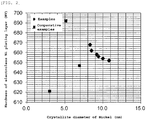
- Fig. 2 illustrates a relationship between the nickel crystallite diameter and hardness of the electroless nickel plating layer of Examples.
- Fig. 3 illustrates a relationship between the nickel crystallite diameter and scratch strength of the electroless nickel plating layer of Examples.
- the nickel crystallite diameter of the samples of Examples was in a range of 8 nm to 11 nm.
- all Examples whose nickel crystallite diameter was in a range of 8 nm to 11 nm had 650 Hv or more in Vickers hardness.
- a Comparative Example (sample No.7) whose nickel crystallite diameter was 5.1 nm had 692 Hv in Vickers hardness, and the reason why high hardness was obtained is due to the combined effect of dispersing the ceramic particles in the electroless nickel plating layer.
- Comparative Examples other than sample No.7 the ceramic particles were not dispersed, and Vickers hardness was less than 650 Hv.
Landscapes
- Chemical & Material Sciences (AREA)
- General Chemical & Material Sciences (AREA)
- Chemical Kinetics & Catalysis (AREA)
- Engineering & Computer Science (AREA)
- Materials Engineering (AREA)
- Mechanical Engineering (AREA)
- Metallurgy (AREA)
- Organic Chemistry (AREA)
- Chemically Coating (AREA)
- Compressor (AREA)
- Applications Or Details Of Rotary Compressors (AREA)
Abstract
Description
- The present disclosure relates to a sliding member of a compressor such as a vane compressor of an air conditioner for a motor vehicle, and applies low-phosphorus nickel plating to the sliding member for the purpose of reducing the cost of the sliding member such as a vane.
- A vane compressor, for example, includes a cam ring, a rotor which is rotatably accommodated in the cam ring and is fixed to a drive shaft, vanes which are inserted into a plurality of vane grooves provided at the rotor, a front side member which is fixed to one end surface of the cam ring, and a rear side member which is fixed to the other end surface of the cam ring. The drive shaft is rotatably supported by the front side member and the rear side member via bearings. For example, a suction port for a working fluid (refrigerant gas) and a suction chamber (a low-pressure chamber) communicating with the suction port are formed in the front side member, and a discharge port for the working fluid and a discharge chamber
- (a high-pressure chamber) communicating with the discharge port are formed in the rear side member (refer to
Figs. 1 to 8 inPatent Literature 1.). - Since a slide between aluminum members are to be avoided, and since hardness for abrasion resistance and toughness against impact are required, hard nickel-phosphorus plating is generally applied to aluminum vanes of the vane compressor (for example, refer to
Patent Literatures 2 to 4.). - Patent Literature 1:
WO2008/026496 - Patent Literature 2:
JP-A-8-158058 - Patent Literature 3:
JP-A-2003-161259 - Patent Literature 4:
JP-A-2003-184743 - The hardness of Ni-P plating increases when applying heat treatment, but the toughness of the plating decreases. Therefore, in order to satisfy both the hardness and toughness, for example, Ni-P-B plating blended with boron is used as described in a technique of
Patent Literature 2 orPatent Literature 3, or for example, Ni-Co-P plating blended with cobalt is used as described in a technique of Patent Literature 4. However, these plating is expensive. - In addition, Ni particles might adhere to a surface of a plated vane and a post-process for removing the Ni particles is required, which increases the cost.
- Therefore, an object of the present disclosure is to provide a sliding member for a compressor whose sliding portion is applied with a plating film, in which both the hardness and toughness of the plating film are good, adhesion of the Ni particles is inhibited, and the plating film is inexpensive.
- The present inventors found that an electroless low-phosphorus nickel plating layer which is a non-heat treated layer and contains Ni crystallites having a crystallite diameter of 8 nm to 11 nm provides both good hardness and toughness of a plating film and solved the problem of the present invention. That is, a sliding member for a compressor according to the present invention is a sliding member for a compressor including a base material formed of an aluminum alloy, and an electroless nickel plating layer containing phosphorus which is formed on a surface of the base material, in which in the electroless nickel plating layer, a phosphorus (P) content is equal to or more than 1.0 mass% and equal to or less than 2.0 mass%, a boron (B) content is equal to or more than 0 mass% and equal to or less than 0.01 mass%, and a cobalt (Co) content is equal to or more than 0 mass% and equal to or less than 0.01 mass%, the electroless nickel plating layer is a non-heat treated layer, the electroless nickel plating layer contains Ni crystallites, and a crystallite diameter of the Ni crystallites measured by an X-ray diffraction method is 8 nm to 11 nm.
- In the sliding member for a compressor according to the present invention, a Vickers hardness of the electroless nickel plating layer is preferably equal to or more than 650 Hv and equal to or less than 750 Hv.
- In the sliding member for a compressor according to the present invention, the electroless nickel plating layer preferably does not contain boron (B) and cobalt (Co). According to the present configuration, a plating solution to be used can be made inexpensive.
- In the sliding member for a compressor according to the present invention, the electroless nickel plating layer is preferably a barrel plating layer. According to the present configuration, Ni particles are prevented from accumulating, and smoothness of the member increases.
- It is preferable that the sliding member for a compressor according to the present invention has an underlayer between the base material and the electroless nickel plating layer, and the underlayer is an electroless nickel plating layer containing 6.0 mass% to 11.0 mass% of phosphorus (P) and a non-heat treated layer. According to the present configuration, since the underlayer is a medium phosphorus type plating layer, adhesion with the base material is good, and smoothness increases.
- In the sliding member for a compressor according to the present invention, the underlayer preferably does not contain boron (B) and cobalt (Co). According to the present configuration, a plating solution to be used can be made inexpensive.
- In the sliding member for a compressor according to the present invention, a film thickness of the electroless nickel plating layer formed on the surface of the base material or a total thickness of the underlayer formed on the surface of the base material and the electroless nickel plating layer is preferably 15 µm to 30 pm. According to the present configuration, the film thickness of the plating film is optimal to a vane to be used.
- In the sliding member for a compressor according to the present invention, the electroless nickel plating layer is preferably a non-dispersion plating film where ceramic particulates do not disperse in the layer. The hardness and scratch strength of the plating film can be improved.
- According to the present disclosure, the sliding member for a compressor whose sliding portion is applied with the plating film can be provided, in which both the hardness and toughness of the plating film are satisfied, adhesion of Ni particles is inhibited, and the plating film is inexpensive.
-
-
Fig. 1 illustrates a relationship between a phosphorus content and a nickel crystallite diameter of an electroless nickel plating layer in Examples. -
Fig. 2 illustrates a relationship between the nickel crystallite diameter and hardness of the electroless nickel plating layer in Examples. -
Fig. 3 illustrates a relationship between the nickel crystallite diameter and scratch strength of the electroless nickel plating layer in Examples. -
Fig. 4 is a sectional view illustrating a configuration example of a vane compressor which includes vanes configuring sliding members according to the present embodiment. -
Fig. 5 is a sectional view taken along a line A-A inFig. 4 . - Hereinafter, an aspect of the present invention will be described with reference to the attached drawings. Embodiments to be described hereinafter are Examples of the present invention, and the present invention is not limited to the embodiments hereinafter. It should be noted that in the present specification and drawings, constituent elements with the same reference numerals mutually indicate the same element. Various modifications may be made as long as the effect of the present invention is achieved.
- First, a sliding member for a compressor will be described. Compressors include a vane compressor, a swash plate compressor and the like.
Fig. 4 andFig. 5 illustrate a configuration of the vane compressor as an example. The vane compressor includes acam ring 1, arotor 3 which is rotatably accommodated in the cam ring and is fixed to adrive shaft 2,vanes 5 which are inserted into a plurality of vane grooves 4 provided at therotor 3, arear side member 6 which is fixed to a rear side end surface of thecam ring 1, and a shell member 7 which surrounds a front side end surface and an outer circumferential surface of thecam ring 1 and is fitted to therear side member 6. Thedrive shaft 2 is rotatably supported by the shell member 7 and therear side member 6 via bearings. Asuction port 8 for a working fluid (refrigerant gas) and a suction chamber (a low-pressure chamber) 9 communicating with thesuction port 8 are formed in the shell member 7, and adischarge port 10 for the working fluid and a discharge chamber (a high-pressure chamber) 11 communicating with thedischarge port 10 are formed in therear side member 6. Acompression space 12 is defined between an inner circumferential surface of thecam ring 1 and an outer circumferential surface of therotor 3. Thecompression space 12 is divided by thevanes 5 to form a plurality ofcompression chambers 13, and a capacity of each compression chamber varies according to rotation of therotor 3. - In the vane compressor, during the rotation of the
rotor 3, sliding occurs between a tip surface of thevane 5 and the inner circumferential surface of thecam ring 1, between two side surfaces of thevane 5 and inner side surfaces of therear side member 6 and the shell member 7, and between both front and back side surfaces of thevane 5 and an inside surface of the vane groove 4. Therefore, besides thevane 5 is required to have high hardness and abrasion resistance, thevane 5 is strongly required that a plating layer formed on the surfaces of thevane 5 is not peeled off, even in a case where foreign matters enter between therotor 3, thecam ring 1 or therear side member 6, and the shell member 7 and a scrape is generated on the surfaces of thevane 5. In a case where a base material of thevane 5 is formed from a material containing aluminum as a main component for the purpose of weight reduction or the like, if a plating film is formed on surfaces of the base material of thevane 5, the requirements of the above-mentioned hardness and peel resistance can be satisfied well. In addition, thecam ring 1, therear side member 6, the shell member 7, therotor 3 and the like of the vane compressor can also be considered as sliding members, and the plating film may be formed on the surfaces thereof, so that the requirements of the hardness and abrasion resistance can also be satisfied. - Similarly, in a case of the swash plate compressor, a plating film is formed in a portion where members are in slide contact with each other, so that the requirements of the hardness and abrasion resistance can also be satisfied.
- A material of the sliding member is, for example, an aluminum-based alloy. Examples of the aluminum-based alloy include an aluminum-based alloy such as 2000 series, 4000 series, 5000 series, 6000 series and 7000 series, and an aluminum alloy having a high silicon content such as ADC10, ADC12, ADC14 and A390. In the present embodiment, the material of the sliding member is preferably an aluminum-based alloy.
- Next, the sliding member for a compressor where the plating film (also called plating layer) is formed will be described. In the sliding member for a compressor according to the present embodiment, an electroless nickel plating layer is formed on at least a sliding portion. That is, the sliding member for a compressor according to the present embodiment is a sliding member for a compressor including a base material formed of an aluminum alloy, and an electroless nickel plating layer containing phosphorus which is formed on a surface of the base material, in which in the electroless nickel plating layer, a phosphorus (P) content is equal to or more than 1.0 mass% and equal to or less than 2.0 mass%, a boron (B) content is equal to or more than 0 mass% and equal to or less than 0.01 mass%, and a cobalt (Co) content is equal to or more than 0 mass% and equal to or less than 0.01 mass%, the electroless nickel plating layer is a non-heat treated layer and contains Ni crystallites, and a crystallite diameter of the crystallites measured by an X-ray diffraction method is 8 nm to 11 nm.
- In the present embodiment, the plating film is deposited and formed by using an electroless plating bath which contains a nickel salt such as nickel sulfate and nickel chloride as a supply source of nickel ions, and a phosphorus compound such as sodium hypophosphite as a reducing agent. A ratio of the nickel salt to the phosphorus compound in the plating bath is appropriately adjusted in accordance with a composition of the plating film. A stabilizer for preventing decomposition of a plating solution and inhibiting plating deposition, a pH adjuster such as sodium hydroxide and aqueous ammonia, a complexing agent containing an organic acid such as sodium acetate and sodium citrate, and a buffer such as sodium citrate can be added into the plating bath. The plating film can be formed by immersing a surface to be plated of the base material in the plating bath for constant time. A temperature of the plating bath is determined in consideration of stability and deposition speed of the bath, but is suitable to be set in a range of, for example, 60°C to 95°C, preferably 70°C to 90°C. In addition, a film thickness of the plating film can be appropriately adjusted by adjusting immersion time in the plating bath.
- The phosphorus (P) content in the electroless nickel plating layer is equal to or more than 1.0 mass% and equal to or less than 2.0 mass%. In general, a nickel plating film having a phosphorus content of 8 mass% to 10 mass% belongs to a "medium phosphorus" type. In addition, a nickel plating film having a phosphorus content of 10 mass% to 11 mass% belongs to a "medium-high phosphorus" type. A nickel plating film which contains these types and has a phosphorus content of 8 mass% to 11 mass% is excellent in ease of using the plating bath, deposition speed of the plating film, and film dispersion, so that a versatility thereof is high. In the present embodiment, the nickel plating film has a phosphorus (P) content being equal to or more than 1.0 mass% and equal to or less than 2.0 mass%, and belongs to a "low phosphorus" type plating film rather than the "medium phosphorus" type and the "medium-high phosphorus" type. When the phosphorus (P) content is less than 1.0 mass%, the electroless nickel plating layer cannot be formed, or a film formation speed slows down. When the phosphorus (P) content exceeds 2.0 mass%, the desired Ni crystallites cannot be obtained. The plating solution for forming the "low phosphorus" type nickel plating layer is difficult to generate Ni particles in terms of the characteristics, and a post-process for removing the Ni particles can be omitted.
- The boron (B) content in the electroless nickel plating layer is equal to or more than 0 mass% and equal to or less than 0.01 mass%, and the electroless nickel plating layer preferably does not contain boron (B). The plating solution is preferably not substantially blended with a boron component. The plating solution can be made inexpensive because boron is not blended.
- The cobalt (Co) content in the electroless nickel plating layer is equal to or more than 0 mass% and equal to or less than 0.01 mass%, and the electroless nickel plating layer preferably does not contain cobalt (Co). The plating solution is preferably not substantially blended with a cobalt component. The plating solution can be made inexpensive because the cobalt component is not blended.
- The electroless nickel plating layer is a non-heat treated layer. Since the electroless nickel plating layer is the non-heat treated layer, toughness of the plating layer can be increased and hardness of the base material does not decrease.
- The electroless nickel plating layer contains the Ni crystallites, and the crystallite diameter of the crystallites, which are measured by the X-ray diffraction method, is 8 nm to 11 nm. A crystallite size is set in this range, so that sufficient hardness is obtained as necessary without a heat treatment. That is, Vickers hardness of the electroless nickel plating layer is 650 Hv to 750 Hv. An upper limit of the Vickers hardness of the electroless nickel plating layer may be 700 Hv. When the crystallite diameter of the crystallites is less than 8 nm, the plating film does not have high hardness, for example, the Vickers hardness is lower than 650 Hv. In a case where the crystallite diameter of the crystallites exceeds 11 nm, the film formation speed slows down, and the film is difficult to be formed.
- The electroless nickel plating layer is preferably a non-dispersion plating film where ceramic particulates do not disperse in the layer. A dispersion plating film where ceramic particulates disperse in the layer provides high hardness. However, since scratch strength of the dispersion plating film tends to be small, it is preferable to satisfy the hardness and the scratch strength without using an effect of a composite in the present embodiment. In addition, since the plating layer does not contain the ceramic particulates, there is no attack to a counterpart member at the time of sliding.
- The electroless nickel plating layer is preferably a barrel plating layer. By combining with a plating method in a barrel form, the Ni particles are prevented from accumulating and smoothness of the member increases.
- It is preferable that the sliding member for a compressor according to the present embodiment includes an underlayer between the base material and the electroless nickel plating layer, and the underlayer is an electroless nickel plating layer containing 6.0 mass% to 11.0 mass% of phosphorus (P), and is a non-heat treated layer. The electroless nickel plating layer of medium to medium-high phosphorus types is provided as the underlayer, so that adhesion with the base material can be improved, and smoothness of the plating film can be increased. Further, the underlayer is provided, so that generation of Ni particles can be inhibited, and a removal process of the Ni particles can be omitted. Phosphorus (P) in the underlayer is preferably 6.5 mass% to 10.5 mass%, and more preferably 7.0 mass% to 10.0 mass%. When the phosphorus (P) in the underlayer is in a range of 6.0 mass% to 11.0 mass%, an electroless nickel plating acquires the most stable film formation reactivity and smoothness. On the contrary, when the phosphorus (P) in the underlayer is less than 6.0 mass%, or exceeds 11.0 mass%, a decrease in reactivity or abnormal particle growth due to an increase in side reaction or the like easily occurs, which causes a problem such as a decrease in smoothness. The underlayer is a non-heat treated layer. Since the underlayer is the non-heat treated layer, the toughness of the plating layer can be increased and the hardness of the base material does not decrease.
- The underlayer preferably does not contain boron (B) and cobalt (Co). Similarly to the electroless nickel plating layer, a plating solution for the underlayer can be made inexpensive.
- In the sliding member for a compressor according to the present embodiment, a film thickness of the electroless nickel plating layer formed on the surface of the base material is preferably 15 pm to 30 pm, and more preferably 18 pm to 25 pm. The film thickness is set to 15 µm to 30 pm, so that the substantial hardness for the abrasion resistance and the toughness against impact can be satisfied. When the film thickness is less than 15 pm, neither the hardness nor the toughness may be satisfied, and when the film thickness exceeds 30 pm, the film may be easily peeled off and productivity may decrease.
- In the sliding member for a compressor according to the present embodiment, a total film thickness of the underlayer formed on the surface of the base material and the electroless nickel plating layer is preferably 15 pm to 30 pm, and more preferably 18 µm to 25 pm. The total film thickness is set to 15 µm to 30 pm, so that the hardness for the abrasion resistance and the toughness against impact can be satisfied. When the total film thickness is less than 15 pm, neither the hardness nor the toughness may be satisfied, and when the total film thickness exceeds 30 pm, the film may be easily peeled off, and the productivity and economy may decrease. In addition, the underlayer formed on the surface of the base material is preferably 1 µm to 15 pm, and more preferably 3 pm to 10 pm. The electroless nickel plating layer formed on the underlayer is preferably 15 µm to 25 pm.
- The present invention will be described more specifically by listing Examples, but the present invention is not limited to the Examples.
- Samples shown in
Samples 1 to 9 were manufactured. The vane made of a high silicon-based aluminum alloy (Al-10.5 mass% to 20 mass% of Si) was immersed in a plating bath shown in Table 1 so as to form the electroless nickel plating layer, and then washed with water. The immersion time was adjusted such that the film thickness is the film thickness shown in Table 1. In a case where the plating film including the underlayer is formed, the vane was first immersed in a plating bath for a underlayer to form the underlayer, and then washed with water. Further, the vane was immersed in a plating bath for an electroless nickel plating layer to form the electroless nickel plating layer on the underlayer, and then washed with water. - Results of
Samples 1 to 9 are shown in Table 1.Table 1 Sample No. Example/ comparative example Aluminum alloy base material Presence/ absence of underlayer Plating bath for electroless nickel plating layer Plating bath for underlayer Phosphorus content in electroless nickel plating layer (mass%) Nickel content in electroless nickel plating layer (mass%) *containing unavoidable impurities Phosphorus content in underlayer (mass%) Nickel content in underlayer (mass%) *containing unavoidable impurities 1 Comparative example Al-10.5Si-4.8 Cu-0.6Mg Absence Plating bath for low phosphorus film manufactured by Company A - 2.56 Remaining part - - 2 Comparative example Al-10.5Si-4.8 Cu-0.6Mg Absence Plating bath For low-medium phosphorus film manufactured by Company B - 6.72 Remaining part - - 3 Example Al-20Si-5Fe-3.5Cu-1.2Mg Absence Plating bath for low phosphorus film manufactured by Uyemura & Co., Ltd. (Nimuden KHN) - 1.22 Remaining part - - Sample No. Example/ comparative example Aluminum alloy base material Presence/ absence of underlayer Plating bath for electroless nickel plating layer Plating bath for underlayer Phosphorus content in electroless nickel plating layer (mass%) Nickel content in electroless nickel plating layer (mass%) *containing unavoidable impurities Phosphorus content in underlayer (mass%) Nickel content in underlayer (mass%) *containing unavoidable impurities 4 Example Al-17Si-5Fe-3.5Cu-1 Mg Presence Plating bath for low phosphorus film manufactured by Uyemura & Co., Ltd. (Nimuden KHN) - 1.66 Remaining part - - Plating Bath For Medium-High Phosphorus Film Manufactured by Uyemura & Co., Ltd. (Nimuden KTY) - - 8.30 remaining part 5 Example Al-17Si-5Fe-3.5Cu-1 Mg Absence Plating bath for low phosphorus film manufactured by Uyemura & Co., Ltd. (Nimuden KHN) - 1.63 Remaining part - - Sample No. Example/ comparative example Aluminum alloy base material Presence/ absence of underlayer Plating bath for electroless nickel plating layer Plating bath for underlayer Phosphorus content in electroless nickel plating layer (mass%) Nickel content in electroless nickel plating layer (mass%) *containing unavoidable impurities Phosphorus content in underlayer (mass%) Nickel content in underlayer (mass%) *containing unavoidable impurities 6 Example Al-20Si-7.5Ni -2.5Cu-1 Mg Presence Plating bath for low phosphorus film manufactured by Uyemura & Co., Ltd. (Nimuden KHN) - 1.08 Remaining part - - Plating bath for medium-high phosphorus film manufactured by Uyemura & Co., Ltd. (Nimuden KTY) - - 8.39 Remaining Part 7 Comparative example Al-10.5Si-4.8 Cu-0.6Mg Absence Plating bath for low phosphorus composite plating film manufactured by Company C - 4.45 Remaining part - - 8 Example Al-10.5Si-4.8 Cu-0.6Mg Absence Plating bath for low phosphorus film manufactured by Coventya Inc. - 1.89 Remaining Part - - Sample No. Example/ comparative example Aluminum alloy base material Presence/ absence of underlayer Plating bath for electroless nickel plating layer Plating bath for underlayer Phosphorus content in electroless nickel plating layer (mass%) Nickel content in electroless nickel plating layer (mass%) *containing unavoidable impurities Phosphorus content in underlayer (mass%) Nickel content in underlayer (mass%) *containing unavoidable impurities 9 Example Al-20Si-5Fe-3.5Cu-1.2Mg Absence Plating bath for low phosphorus film manufactured By Coventya Inc. - 1.60 Remaining Part - - *Processing condition is according to the standard condition of each company Sample No. Example/ comparative example Ni crystallite diameter of electro less nickel plating layer (nm) Film thickness (µm) Total film thickness (µm) Hardness (HV) Scratch strength (N) Remarks 1 Comparative example 6.9 24.9 24.9 647 26.6 - 2 Comparative example 3.0 17.8 17.8 621 12.0 - 3 Example 10.0 23.2 23.2 654 98 or greater - 4 Example 9.4 23.0 26.0 656 98 or greater - 3.0 5 Example 9.2 24.0 24.0 658 98 or greater - 6 Example 10.8 16.8 20.0 652 98 or greater - 3.2 7 Comparative example 5.1 20.4 20.4 692 18.0 Blending ceramic particles to plating film 8 Example 8.3 21.0 21.0 668 98 or greater - 9 Example 8.5 27.7 27.7 662 98 or greater - *Processing condition is according to the standard condition of each company - Compositions of the electroless nickel plating layer and the underlayer were determined by an X-ray fluorescent analysis method.
- The nickel crystallite diameter in the electroless nickel plating layer was determined by the X-ray diffraction method.
- The film thickness was determined by measurement according to an enlarged observation from a cut surface using an optical microscope.
- The hardness of the electroless nickel plating layer or the hardness of the electroless nickel plating layer including the underlayer was determined by a micro Vickers hardness meter (JIS Z 2244-2009).
- A scratch test was carried out on the electroless nickel plating layer or the electroless nickel plating layer including the underlayer. A load variation type friction abrasion system HHS3000 manufactured by SHINTO Scientific Co., ltd. was used in the scratch test, an indenter which includes a conical tip end portion made of diamond and having an apex angle of 120° and a curvature radius of a tip end of 0.2 mm was used as a measurement indenter, and a load at a position where a crack was firstly confirmed in scratch traces formed by sweeping the plating film surface in a length range of 10 mm in a vertical direction while proportionally and gradually increasing from 0 N to 98 N was determined from a sweeping distance as the scratch strength.
-
Fig. 1 illustrates a relationship between a phosphorus content and a nickel crystallite diameter of an electroless nickel plating layer of Examples. -
Fig. 2 illustrates a relationship between the nickel crystallite diameter and hardness of the electroless nickel plating layer of Examples. -
Fig. 3 illustrates a relationship between the nickel crystallite diameter and scratch strength of the electroless nickel plating layer of Examples. - As illustrated in
Fig. 1 , the nickel crystallite diameter of the samples of Examples was in a range of 8 nm to 11 nm. As illustrated inFig. 2 , all Examples whose nickel crystallite diameter was in a range of 8 nm to 11 nm had 650 Hv or more in Vickers hardness. InFig. 2 , a Comparative Example (sample No.7) whose nickel crystallite diameter was 5.1 nm had 692 Hv in Vickers hardness, and the reason why high hardness was obtained is due to the combined effect of dispersing the ceramic particles in the electroless nickel plating layer. In Comparative Examples other than sample No.7, the ceramic particles were not dispersed, and Vickers hardness was less than 650 Hv. As illustrated inFig. 3 , all Examples whose nickel crystallite diameter was in a range of 8 nm to 11 nm had 98 N or more in scratch strength. InFig. 3 , Comparative Example (sample No.7) whose nickel crystallite diameter was 5.1 nm had the scratch strength as small as 18.0 N. In Comparative Example of sample No.7, as illustrated inFig. 2 , the Vickers hardness was high, but the scratch strength was small, and the high Vickers hardness and the large scratch strength could not be compatible. - In the Examples, adhesion of Ni particles is inhibited.
-
- 1
- cam ring
- 1a
- flange portion
- 2
- drive shaft
- 3
- rotor
- 4
- vane groove
- 5
- vane
- 6
- rear side member
- 7
- shell member
- 6a, 7a
- side block portion
- 6b, 7b
- head portion
- 8
- suction port
- 9
- low-pressure chamber
- 10
- discharge port
- 11
- high-pressure chamber
- 11a
- first high-pressure chamber
- 11b
- second high-pressure chamber
- 12
- compression space
- 13
- compression chamber
- 15
- discharge valve accommodation chamber
- 17
- through hole
Claims (8)
- A sliding member for a compressor comprising:a base material formed of an aluminum alloy; andan electroless nickel plating layer containing phosphorus which is formed on a surface of the base material,wherein in the electroless nickel plating layer, a phosphorus (P) content is equal to or more than 1.0 mass% and equal to or less than 2.0 mass%, a boron (B) content is equal to or more than 0 mass% and equal to or less than 0.01 mass%, and a cobalt (Co) content is equal to or more than 0 mass% and equal to or less than 0.01 mass%,wherein the electroless nickel plating layer is a non-heat treated layer, andwherein the electroless nickel plating layer contains Ni crystallites, and a crystallite diameter of the crystallites measured by an X-ray diffraction method is 8 nm to 11 nm.
- The sliding member for a compressor according to claim 1, wherein a Vickers hardness of the electroless nickel plating layer is equal to or more than 650 Hv and equal to or less than 750 Hv.
- The sliding member for a compressor according to claim 1 or 2, wherein the electroless nickel plating layer does not contain boron (B) and cobalt (Co).
- The sliding member for a compressor according to any one of claims 1 to 3, wherein the electroless nickel plating layer is a barrel plating layer.
- The sliding member for a compressor according to any one of claims 1 to 4 further comprising:an underlayer between the base material and the electroless nickel plating layer,wherein the underlayer is an electroless nickel plating layer containing 6.0 mass% to 11.0 mass% of phosphorus (P), and is a non-heat treated layer.
- The sliding member for a compressor according to claim 5, wherein the underlayer does not contain boron (B) and cobalt (Co) .
- The sliding member for a compressor according to any one of claims 1 to 6, wherein a film thickness of the electroless nickel plating layer formed on the surface of the base material or a total film thickness of the underlayer formed on the surface of the base material and the electroless nickel plating layer is 15 µm to 30 pm.
- The sliding member for a compressor according to any one of claims 1 to 7, wherein the electroless nickel plating layer is a non-dispersion plating film where ceramic particulates do not disperse in the layer.
Applications Claiming Priority (1)
| Application Number | Priority Date | Filing Date | Title |
|---|---|---|---|
| JP2017184051A JP6951175B2 (en) | 2017-09-25 | 2017-09-25 | Sliding member for compressor |
Publications (1)
| Publication Number | Publication Date |
|---|---|
| EP3460096A1 true EP3460096A1 (en) | 2019-03-27 |
Family
ID=63683029
Family Applications (1)
| Application Number | Title | Priority Date | Filing Date |
|---|---|---|---|
| EP18196195.4A Pending EP3460096A1 (en) | 2017-09-25 | 2018-09-24 | Sliding member for compressor |
Country Status (2)
| Country | Link |
|---|---|
| EP (1) | EP3460096A1 (en) |
| JP (1) | JP6951175B2 (en) |
Cited By (2)
| Publication number | Priority date | Publication date | Assignee | Title |
|---|---|---|---|---|
| CN116717536A (en) * | 2023-07-28 | 2023-09-08 | 西安庆安制冷设备股份有限公司 | A crankshaft structure, pump body assembly and compressor |
| CN117926233A (en) * | 2024-03-21 | 2024-04-26 | 山东天瑞重工有限公司 | Nickel-phosphorus plating solution for 7075 aluminum alloy double-layer chemical plating and preparation method of 7075 aluminum alloy with chemical plating layer on surface |
Families Citing this family (1)
| Publication number | Priority date | Publication date | Assignee | Title |
|---|---|---|---|---|
| JP2023088435A (en) | 2021-12-15 | 2023-06-27 | サンデン株式会社 | Electroless Ni-P plating film for sliding member and manufacturing method thereof |
Citations (6)
| Publication number | Priority date | Publication date | Assignee | Title |
|---|---|---|---|---|
| JPH08158058A (en) | 1994-11-29 | 1996-06-18 | Nippon Kanizen Kk | Nickel-phosphorus-boron based electroless plated film and machine parts using the same |
| JPH1096084A (en) * | 1996-09-20 | 1998-04-14 | Taiho Kogyo Co Ltd | Surface treatment method for sliding members |
| JPH1172042A (en) * | 1997-08-29 | 1999-03-16 | Unisia Jecs Corp | Internal combustion engine piston |
| JP2003161259A (en) | 2001-11-22 | 2003-06-06 | Toyota Industries Corp | Sliding material for compressor |
| JP2003184743A (en) | 2001-12-12 | 2003-07-03 | Toyota Industries Corp | Shoe for swash plate type compressor and swash type compressor provided therewith |
| WO2008026496A1 (en) | 2006-08-29 | 2008-03-06 | Valeo Thermal Systems Japan Corporation | Movable vane compressor |
Family Cites Families (1)
| Publication number | Priority date | Publication date | Assignee | Title |
|---|---|---|---|---|
| WO1998031849A1 (en) * | 1997-01-20 | 1998-07-23 | Taiho Kogyo Co., Ltd. | Sliding member, method of treating surface of the sliding member and rotary compressor vane |
-
2017
- 2017-09-25 JP JP2017184051A patent/JP6951175B2/en active Active
-
2018
- 2018-09-24 EP EP18196195.4A patent/EP3460096A1/en active Pending
Patent Citations (6)
| Publication number | Priority date | Publication date | Assignee | Title |
|---|---|---|---|---|
| JPH08158058A (en) | 1994-11-29 | 1996-06-18 | Nippon Kanizen Kk | Nickel-phosphorus-boron based electroless plated film and machine parts using the same |
| JPH1096084A (en) * | 1996-09-20 | 1998-04-14 | Taiho Kogyo Co Ltd | Surface treatment method for sliding members |
| JPH1172042A (en) * | 1997-08-29 | 1999-03-16 | Unisia Jecs Corp | Internal combustion engine piston |
| JP2003161259A (en) | 2001-11-22 | 2003-06-06 | Toyota Industries Corp | Sliding material for compressor |
| JP2003184743A (en) | 2001-12-12 | 2003-07-03 | Toyota Industries Corp | Shoe for swash plate type compressor and swash type compressor provided therewith |
| WO2008026496A1 (en) | 2006-08-29 | 2008-03-06 | Valeo Thermal Systems Japan Corporation | Movable vane compressor |
Cited By (2)
| Publication number | Priority date | Publication date | Assignee | Title |
|---|---|---|---|---|
| CN116717536A (en) * | 2023-07-28 | 2023-09-08 | 西安庆安制冷设备股份有限公司 | A crankshaft structure, pump body assembly and compressor |
| CN117926233A (en) * | 2024-03-21 | 2024-04-26 | 山东天瑞重工有限公司 | Nickel-phosphorus plating solution for 7075 aluminum alloy double-layer chemical plating and preparation method of 7075 aluminum alloy with chemical plating layer on surface |
Also Published As
| Publication number | Publication date |
|---|---|
| JP6951175B2 (en) | 2021-10-20 |
| JP2019060259A (en) | 2019-04-18 |
Similar Documents
| Publication | Publication Date | Title |
|---|---|---|
| Agarwala et al. | Electroless alloy/composite coatings: A review | |
| EP2443267B1 (en) | Protective coating, a coated member having a protective coating as well as method for producing a protective coating | |
| CN101900108B (en) | Sliding member for compressor | |
| CN104812925B (en) | Arc PVD coatings with enhanced anti-friction and anti-wear properties | |
| JP6951175B2 (en) | Sliding member for compressor | |
| US20130143031A1 (en) | Electroless ni-composite plated substrate and method | |
| CN209083559U (en) | A kind of rotor-type compressor and air conditioner | |
| EP1083246B1 (en) | Conversion coating of tin with cobalt and bismuth for aluminum sliding surfaces | |
| CN1421607A (en) | Sliding element for compressor | |
| EP3460095B1 (en) | Sliding member | |
| EP1052306B1 (en) | Metal-based gradient composite material having good lubrication and wear resistance property, the production and the use of the same | |
| JP3408366B2 (en) | Sliding member for compressor | |
| JP2002510016A (en) | Cobalt-tin alloy coating on aluminum by chemical conversion treatment | |
| US3989558A (en) | Coating and diffusion process for improving the life of cobalt-bonded sintered carbide tools | |
| JP2697768B2 (en) | Vane type compressor | |
| EP3017896A1 (en) | Surface-coated boron nitride sintered tool | |
| US20250034717A1 (en) | Electroless ni-p plating film for sliding member and manufacturing method therefor | |
| CN1163631C (en) | Coated Turning Inserts | |
| US3785783A (en) | Ruthenium or osmium on hard metal | |
| EP3017897B1 (en) | Surface-coated boron nitride sintered body tool | |
| WO2020217738A1 (en) | Eutectoid plating solution | |
| JP4332632B2 (en) | Gas compressor | |
| CN104043848A (en) | Surface-coated cutting tool having excellent lubricating property | |
| JP2022091384A (en) | Eutectoid plating solution | |
| JP2001302335A (en) | Aluminum oxide-containing composite ceramic sintered compact and coated composite ceramic sintered compact |
Legal Events
| Date | Code | Title | Description |
|---|---|---|---|
| PUAI | Public reference made under article 153(3) epc to a published international application that has entered the european phase |
Free format text: ORIGINAL CODE: 0009012 |
|
| STAA | Information on the status of an ep patent application or granted ep patent |
Free format text: STATUS: THE APPLICATION HAS BEEN PUBLISHED |
|
| AK | Designated contracting states |
Kind code of ref document: A1 Designated state(s): AL AT BE BG CH CY CZ DE DK EE ES FI FR GB GR HR HU IE IS IT LI LT LU LV MC MK MT NL NO PL PT RO RS SE SI SK SM TR |
|
| AX | Request for extension of the european patent |
Extension state: BA ME |
|
| STAA | Information on the status of an ep patent application or granted ep patent |
Free format text: STATUS: REQUEST FOR EXAMINATION WAS MADE |
|
| 17P | Request for examination filed |
Effective date: 20190924 |
|
| RBV | Designated contracting states (corrected) |
Designated state(s): AL AT BE BG CH CY CZ DE DK EE ES FI FR GB GR HR HU IE IS IT LI LT LU LV MC MK MT NL NO PL PT RO RS SE SI SK SM TR |
|
| STAA | Information on the status of an ep patent application or granted ep patent |
Free format text: STATUS: EXAMINATION IS IN PROGRESS |
|
| 17Q | First examination report despatched |
Effective date: 20220412 |
|
| P01 | Opt-out of the competence of the unified patent court (upc) registered |
Effective date: 20230629 |
|
| RAP1 | Party data changed (applicant data changed or rights of an application transferred) |
Owner name: VALEO ELECTRIFICATION |