EP3459682B1 - 3d-tool-verfolgung und -positionierung mithilfe von kameras - Google Patents
3d-tool-verfolgung und -positionierung mithilfe von kameras Download PDFInfo
- Publication number
- EP3459682B1 EP3459682B1 EP18191145.4A EP18191145A EP3459682B1 EP 3459682 B1 EP3459682 B1 EP 3459682B1 EP 18191145 A EP18191145 A EP 18191145A EP 3459682 B1 EP3459682 B1 EP 3459682B1
- Authority
- EP
- European Patent Office
- Prior art keywords
- patches
- image
- tool
- patch
- computer
- Prior art date
- Legal status (The legal status is an assumption and is not a legal conclusion. Google has not performed a legal analysis and makes no representation as to the accuracy of the status listed.)
- Active
Links
Images




Classifications
-
- G—PHYSICS
- G06—COMPUTING OR CALCULATING; COUNTING
- G06V—IMAGE OR VIDEO RECOGNITION OR UNDERSTANDING
- G06V10/00—Arrangements for image or video recognition or understanding
- G06V10/70—Arrangements for image or video recognition or understanding using pattern recognition or machine learning
- G06V10/82—Arrangements for image or video recognition or understanding using pattern recognition or machine learning using neural networks
-
- B—PERFORMING OPERATIONS; TRANSPORTING
- B25—HAND TOOLS; PORTABLE POWER-DRIVEN TOOLS; MANIPULATORS
- B25F—COMBINATION OR MULTI-PURPOSE TOOLS NOT OTHERWISE PROVIDED FOR; DETAILS OR COMPONENTS OF PORTABLE POWER-DRIVEN TOOLS NOT PARTICULARLY RELATED TO THE OPERATIONS PERFORMED AND NOT OTHERWISE PROVIDED FOR
- B25F5/00—Details or components of portable power-driven tools not particularly related to the operations performed and not otherwise provided for
-
- G—PHYSICS
- G06—COMPUTING OR CALCULATING; COUNTING
- G06F—ELECTRIC DIGITAL DATA PROCESSING
- G06F18/00—Pattern recognition
- G06F18/20—Analysing
- G06F18/24—Classification techniques
- G06F18/241—Classification techniques relating to the classification model, e.g. parametric or non-parametric approaches
- G06F18/2413—Classification techniques relating to the classification model, e.g. parametric or non-parametric approaches based on distances to training or reference patterns
- G06F18/24133—Distances to prototypes
-
- G—PHYSICS
- G06—COMPUTING OR CALCULATING; COUNTING
- G06T—IMAGE DATA PROCESSING OR GENERATION, IN GENERAL
- G06T7/00—Image analysis
- G06T7/10—Segmentation; Edge detection
- G06T7/11—Region-based segmentation
-
- G—PHYSICS
- G06—COMPUTING OR CALCULATING; COUNTING
- G06T—IMAGE DATA PROCESSING OR GENERATION, IN GENERAL
- G06T7/00—Image analysis
- G06T7/20—Analysis of motion
- G06T7/246—Analysis of motion using feature-based methods, e.g. the tracking of corners or segments
- G06T7/248—Analysis of motion using feature-based methods, e.g. the tracking of corners or segments involving reference images or patches
-
- G—PHYSICS
- G06—COMPUTING OR CALCULATING; COUNTING
- G06T—IMAGE DATA PROCESSING OR GENERATION, IN GENERAL
- G06T7/00—Image analysis
- G06T7/20—Analysis of motion
- G06T7/292—Multi-camera tracking
-
- G—PHYSICS
- G06—COMPUTING OR CALCULATING; COUNTING
- G06T—IMAGE DATA PROCESSING OR GENERATION, IN GENERAL
- G06T7/00—Image analysis
- G06T7/70—Determining position or orientation of objects or cameras
- G06T7/73—Determining position or orientation of objects or cameras using feature-based methods
- G06T7/74—Determining position or orientation of objects or cameras using feature-based methods involving reference images or patches
-
- G—PHYSICS
- G06—COMPUTING OR CALCULATING; COUNTING
- G06V—IMAGE OR VIDEO RECOGNITION OR UNDERSTANDING
- G06V10/00—Arrangements for image or video recognition or understanding
- G06V10/40—Extraction of image or video features
- G06V10/44—Local feature extraction by analysis of parts of the pattern, e.g. by detecting edges, contours, loops, corners, strokes or intersections; Connectivity analysis, e.g. of connected components
- G06V10/443—Local feature extraction by analysis of parts of the pattern, e.g. by detecting edges, contours, loops, corners, strokes or intersections; Connectivity analysis, e.g. of connected components by matching or filtering
- G06V10/449—Biologically inspired filters, e.g. difference of Gaussians [DoG] or Gabor filters
- G06V10/451—Biologically inspired filters, e.g. difference of Gaussians [DoG] or Gabor filters with interaction between the filter responses, e.g. cortical complex cells
- G06V10/454—Integrating the filters into a hierarchical structure, e.g. convolutional neural networks [CNN]
-
- G—PHYSICS
- G06—COMPUTING OR CALCULATING; COUNTING
- G06V—IMAGE OR VIDEO RECOGNITION OR UNDERSTANDING
- G06V10/00—Arrangements for image or video recognition or understanding
- G06V10/70—Arrangements for image or video recognition or understanding using pattern recognition or machine learning
- G06V10/764—Arrangements for image or video recognition or understanding using pattern recognition or machine learning using classification, e.g. of video objects
-
- G—PHYSICS
- G06—COMPUTING OR CALCULATING; COUNTING
- G06V—IMAGE OR VIDEO RECOGNITION OR UNDERSTANDING
- G06V20/00—Scenes; Scene-specific elements
- G06V20/60—Type of objects
- G06V20/64—Three-dimensional [3D] objects
-
- G—PHYSICS
- G06—COMPUTING OR CALCULATING; COUNTING
- G06T—IMAGE DATA PROCESSING OR GENERATION, IN GENERAL
- G06T2200/00—Indexing scheme for image data processing or generation, in general
- G06T2200/04—Indexing scheme for image data processing or generation, in general involving 3D image data
-
- G—PHYSICS
- G06—COMPUTING OR CALCULATING; COUNTING
- G06T—IMAGE DATA PROCESSING OR GENERATION, IN GENERAL
- G06T2207/00—Indexing scheme for image analysis or image enhancement
- G06T2207/10—Image acquisition modality
- G06T2207/10028—Range image; Depth image; 3D point clouds
-
- G—PHYSICS
- G06—COMPUTING OR CALCULATING; COUNTING
- G06T—IMAGE DATA PROCESSING OR GENERATION, IN GENERAL
- G06T2207/00—Indexing scheme for image analysis or image enhancement
- G06T2207/20—Special algorithmic details
- G06T2207/20021—Dividing image into blocks, subimages or windows
-
- G—PHYSICS
- G06—COMPUTING OR CALCULATING; COUNTING
- G06T—IMAGE DATA PROCESSING OR GENERATION, IN GENERAL
- G06T2207/00—Indexing scheme for image analysis or image enhancement
- G06T2207/20—Special algorithmic details
- G06T2207/20081—Training; Learning
-
- G—PHYSICS
- G06—COMPUTING OR CALCULATING; COUNTING
- G06T—IMAGE DATA PROCESSING OR GENERATION, IN GENERAL
- G06T2207/00—Indexing scheme for image analysis or image enhancement
- G06T2207/30—Subject of image; Context of image processing
- G06T2207/30196—Human being; Person
-
- G—PHYSICS
- G06—COMPUTING OR CALCULATING; COUNTING
- G06T—IMAGE DATA PROCESSING OR GENERATION, IN GENERAL
- G06T2207/00—Indexing scheme for image analysis or image enhancement
- G06T2207/30—Subject of image; Context of image processing
- G06T2207/30232—Surveillance
Definitions
- This disclosure relates to systems and methods that facilitate positioning points and objects in a work space or at a worksite, such as for example at a construction site.
- a worksite such as for example at a construction site.
- connectors, anchors, and the like are attached to the floors, ceilings and other structures in the building, and cuts are made and holes drilled using power saws and drills.
- Many tasks are accomplished using special power tools at predetermined locations, such that the tools are operated at numerous, precisely-defined positions in the building.
- nail guns, power saws, power-anchor tools, and the like are used to nail, cut, install fasteners, and perform other operations at predetermined points within the building.
- a large number of electrical, plumbing, and HVAC components are properly sited and installed, usually with power tools.
- finishing a building interior also uses a number of different tools that are not powered, yet are to be operated at precisely defined positions, such as for example reinforcement bar scanners. Positioning both power tools and non-power tools is to be accomplished quickly and with some precision with respect to the surrounding walls, ceilings, and floors as they are roughed in. Typically, it has used a significant amount of labor to lay out various construction points at a construction site. Teams of workers have been used to measure and mark predetermined locations. It will be appreciated that this process has been subject to errors, resulting from measurement mistakes and from accumulated errors. Further, the cost of this layout process and the time needed to perform the layout process have both been significant.
- Various location determining systems including systems that incorporate one or more robotic total stations, have been used for building layout.
- the total station in such a system positioned at a fixed, known location, directs a beam of laser light at a retro-reflective target.
- robotics in the total station cause the beam of light to track the target. Since the dimensional coordinates of the total station are known, the dimensional coordinates of the retro-reflective target can be determined. Based on the measured position of the retro-reflective target, and the desired position of some building feature, such as a drilled hole and/ or a fastener, the operator can move the reflector to the desired position, and mark the position.
- US 2011/044545 A1 discloses systems and methods that determine a largest patch size to traverse a digital image, analyze the digital image to detect one or more first objects of a size approximately the same as the largest patch size, and discontinue analyzing the digital image when the digital image includes the first object(s) of a size approximately the same as the largest patch size.
- DE 10 2013 211930 A1 discloses a method of tracking a target using a binocular system including capturing first and second images, the first image being captured by a first camera device and the second image being captured by a second camera device.
- WO 2016/100814 A1 discloses a method that includes fusing multi-modal sensor data from a plurality of sensors having different modalities, wherein a model that uses a deep convolutional neural network is applied to one or more patches of interest.
- a target e.g., a tool, such as a drill
- Current tracking algorithms e.g., scale-invariant feature transform (SIFT) and histogram of oriented gradients (HOG)
- SIFT scale-invariant feature transform
- HOG histogram of oriented gradients
- Deep learning has become more reliable, yet deep learning has difficulty in identifying objects of different sizes.
- different sizes of patches of an image are used to identify objects.
- a patch is a two-dimensional area of an image.
- a computer neural network is trained to identify an object. Training is performed without changing a scale of the object.
- To detect the object at a worksite a camera acquires an image of a scene with the object in the scene.
- the object could be close to the camera or far from the camera, making it difficult for the computer neural network to identify the object in the image, since the computer neural network was trained to detect the object without changing the scale of the object.
- the image is divided into smaller and smaller patches, and object detection is performed on the patches, until the object is found (and/or until a minimum patch size is reached).
- the image is divided into a first number of patches (e.g., 4, 9, 16, 25, and/or 36 patches) to generate a first set of patches.
- the computer neural network reviews the first set of patches.
- the image is divided into a second number of patches (e.g., 25, 30, 36, 56, 64, 81, and/or 100 patches) to generate a second set of patches.
- the computer neural network reviews the second set of patches. If the object is not detected in the second set of patches, the image is divided into a third number of patches (e.g., 256, 1024, and/or 4096 patches) to generate a third set of patches.
- the computer neural network then reviews the third set of patches for the object. The number of patches keeps increasing until the object is identified and/or a minimum patch size is reached (e.g., a minimum patch size is 10 pixels x 10 pixels).
- a system for detecting a tool in a scene comprises: a camera unit for acquiring an image of a scene; and one or more processors configured to: divide the image into a first number of patches to generate a first set of patches, wherein a patch is an area of the image, perform object detection on the first set of patches to identify the tool in a patch of the first set of patches, determine that the tool is not detected in the first set of patches, divide the image into a second number of patches to generate a second set of patches, after determining that the tool is not detected in the first set of patches, perform object detection on the second set of patches to identify the tool in a patch of the second set of patches, and/or determine that the tool is detected in a patch of the second set of patches.
- the camera unit is a first camera unit
- the one or more processors is a first processor unit
- the image is a first image
- the system further comprises: a second camera unit configured to acquire a second image, and/or a second processor unit configured to determine a position of the tool in three dimensions based on the first image and the second image.
- the system further comprises a display, and the one or more processors is further configured to display an indication of the tool overlaying an image on the display; and/or the indication of the tool is a heat map.
- a method for detecting a tool in a scene comprises acquiring an image of the scene; dividing the image into a first number of patches to generate a first set of patches, wherein a patch is an area of the image; performing object detection on the first set of patches to identify the tool in a patch of the first set of patches; determining that the tool is not detected in the first set of patches; dividing the image into a second number of patches to generate a second set of patches, after determining that the tool is not detected in the first set of patches; performing object detection on the second set of patches to identify the tool in a patch of the second set of patches; and/or determining that the tool is detected in a patch of the second set of patches.
- the method comprises dividing the image into a third number of patches to generate a third set of patches, after determining that the tool is not detected in the first set of patches and before dividing the image into a second number of patches; performing object detection on the third set of patches to identify the tool in a patch of the third set of patches; determining that the tool is not detected in the third set of patches; calculating a three-dimensional position of the tool based on the image from a first camera unit, wherein the image is a first image, and a second image from a second camera unit; training a computer neural network to identify the tool before acquiring the image of the scene; determining not to divide the image into a third number of patches based on the determining that the tool is detected in a patch of the second set of patches, wherein the third number of patches is greater than the second number of patches; and/or acquiring the image of the scene using a camera unit having two or more image sensors.
- the first number of patches is less than the second number of patches; the third number of patches is greater than the first number of patches and less than the second number of patches; performing object detection comprises: dividing a patch into a number of cells, and/or calculating a probability of a part of the tool being in a cell; the patches of the first set of patches and/or the second set of patches are rectangular; the patches of the first set of patches are equal in size; a first patch of the first set of patches is not equal in size to a second patch of the first set of patches; the tool is a first tool and the method further comprises detecting a second tool in the first set of patches; and/or the computer neural network is trained at a scale, and/or the scale is used for: performing object detection on the first set of patches, and/or performing object detection on the second set of patches.
- a memory device comprising instructions that cause one or more processors to perform the following steps for detecting a tool in a scene: obtain an image of the scene; divide the image into a first number of patches to generate a first set of patches, wherein a patch is an area of the image; perform object detection on the first set of patches to identify the tool in a patch of the first set of patches; determine that the tool is not detected in the first set of patches; divide the image into a second number of patches to generate a second set of patches, after determining that the tool is not detected in the first set of patches; perform object detection on the second set of patches to identify the tool in a patch of the second set of patches; and/or determine that the tool is detected in a patch of the second set of patches.
- the memory device is part of a camera unit.
- finishing a building interior also uses a number of different tools that are not powered, which are also operated at precisely-defined positions, such as for example reinforcement bar scanners. Positioning both power tools and non-power tools quickly and with precision (e.g., with respect to surrounding walls, ceilings, and floors) can save time and reduce construction costs.
- systems and/or methods are described to speed up, reduce manual labor, and/or reduce expense of construction.
- the camera system comprises camera units 108 and a main processing computer.
- the camera system comprises two or more camera units 108.
- the camera system comprises two or more measurement sticks 104, and/or two or more main processing computers.
- a camera unit 108 comprises a processor unit, a communication device, and/or one or more imaging devices 112 (e.g., two and/or three imaging devices 112).
- the imaging devices 112 have a position and/or orientation that is known relative to other imaging device(s) 112 and/or camera unit(s) 108.
- the imaging devices 112 acquire image sequences.
- the processor unit in the camera unit 108 processes the image sequences.
- the communication device transmits and receives data with the main processing computer.
- FIG. 2 a simplified drawing of an embodiment of a configuration of camera units 108 at a worksite is shown.
- An operator attaches camera units 108 to a column, wall, etc.
- the operator can add and/or subtract camera units 108 depending on a size of the worksite and/or a position of the camera unit 108.
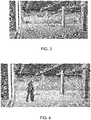
- FIG. 3 depicts a simplified perspective drawing of an embodiment of camera units 108 placed in a worksite.
- the operator attaches the camera units 108 to a column 304, wall 308, ceiling 312, floor 316, truss 320, etc.
- Camera units 108 which are modular, allow for quick setup.
- FIG. 4 depicts a simplified perspective drawing of an example of direct fastening on Pan-Decking.
- FIG. 5 depicts a simplified perspective drawing of an example of drilling and/or direct fastening on a ceiling while a user is on a scissor lift.
- the main computer processor is capable of finding and tracking various tools 404 (e.g., construction tools).
- System memory may include data defining a digital image and/or dimensions of each of a plurality of tools 404 so that the main computer processor can distinguish between the plurality of tools 404 used.
- a position and/or orientation of a tool 404 is determined based on a recognition of an overall three-dimensional image of the tool 404 and/or on certain features of the tool 404.
- certain features of the tool 404 are added to the tool 404 for a purpose of determining the position and/or orientation of the tool 404. In some embodiments, certain features of the tool 404 are built into the tool 404 for a purpose other than for determining the position and/or orientation of the tool 404.
- FIG. 6 depicts a simplified perspective drawing of an example of camera units 108 used for monitoring personnel 604 and/or tracking multiple tools 404.
- the main computer processor is configured to identify and track personnel 604.
- camera units 108 can be used as a surveillance system for safety and/or security.
- two or more tools 404 are tracked.
- two or more camera units 108 are used to acquire two or more images to calculate a three-dimensional position of the tool 404 based on images from the two or more camera units 108.
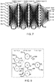
- FIG. 7 depicts a simplified diagram of an embodiment of a computer neural network. Deep learning is inspired by simulating a nerve structure of a brain, as shown in FIG. 7 .
- the computer neural network comprises nodes 704 and connectors 708. Not all nodes 704 and/or connectors 708 are identified with a number designator to reduce clutter in figures.
- the computer neural network comprises an input layer, one or more hidden layers, and an output layer. An output of a node 704 depends on one or more connections 708 to one or more nodes 704 in one or more previous layers and/or input(s).
- a connection weight, associated with a connection 708, decides contributions of the connection 708 to the computer neural network.
- a computer neural network is defined by its architecture and connection weights of connectors 708.
- FIG. 8 depicts a simplified diagram of an embodiment of connectors 708 and weights in a computer neural network.
- the computer neural network is trained (e.g., before detecting a target in an image). Training is achieved by feeding the computer neural network a large set of examples to adjust weights of connectors 708, while making an output of the computer neural network close to values a user defines.
- image classification is complicated due to numerous image patches with different locations and scales. Even with help of generating potential candidate image patches, image classification has been slow.
- the computer neural network is trained to detect a target at once, not incrementally, such that all training data is used at once.
- outputs of the computer neural network are treated as different categories, which represent different orientations of the target. After outputting a category, the network is fed the image patch again at the output location the category represents.
- categories refer to labels used in training (e.g., different types of construction tools, human, etc.).
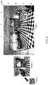
- FIG. 9 depicts an embodiment of an image divided into patches. Target location is refined by reducing sizes of patches from course to fine.
- Fig. 9 show an image 904 divided into a first number of patches to generate a first set of patches 908-1, a second number of patches to generate a second set of patches 908-2, and a third number of patches to generate a third set of patches 908-3.
- the first set of patches 908-1 are considered "course" (e.g., the first set of patches 908-1 has the largest patch size).
- the second set of patches 908-2 are considered “fine” (e.g., the second set of patches 908-1 has the smallest patch size).
- the third set of patches 908-3 is intermediary (in some embodiments there are more intermediary sets of patches, such as a fourth set of patches, a fifth set of patches, a sixth set of patches, and so on).
- the first number of patches is less than the second number of patches.
- the third number of patches (and other intermediary number of patches) is greater than the first number of patches and less than the second number of patches.
- patches of the first set of patches are of equal area.
- the first number of patches is 16 (4x4) with quadrant rows labeled 1 through 4 and quadrant columns labeled A through D.
- each quadrant is one patch.
- patches of a set of patches are not equal in size. For example, if a previous image detected parts of the target in and/or near quadrants A2, A3, B2, and B3, then quadrants A2, A3, B2, and B3 could have different patch sizes than quadrants A1, A4, B1, B4, C1-C4, and D1-D4.
- quadrants A1, A4, B1, B4, C1-C4, and D1-D4 could each have one patch a size of a quadrant, and quadrants A2, A3, B2, and B3 could be divided into patches similar to a patch size the target was detected in the previous image (e.g., quadrant A3 could be divided into 64 patches; and patch size could increase if the target is not identified in quadrant A3).
- a target is tracked by a reference, such as a person (e.g., quadrants identified at and/or near a person have smaller or larger patch sizes based on a size of the person in the image; a size of a detected person providing an initial patch size for one or more quadrants with and/or adjacent to the person).
- FIG. 10 depicts an embodiment of a patch 1004 divided into cells 1008 to identify parts of a target.
- a patch 1004 is divided into cells 1008.
- Parts of a target sometimes referred to as "key parts," 1012 are identified to localize the target.
- a key part is a part of a target to be identified to localize the target.
- not all key parts of the target are identified in a given frame and/or in any frame.
- Probabilities of a key part located in a given cell 1008 are calculated. In some embodiments, probabilities of a target being in each cell 1008 are summed to equal one.
- a three-dimensional position of the target can be calculated using the first image, the second image, and relative position and/or orientation between the first camera unit and the second camera unit.
- outputs from the computer neural network calculate a probability of a given key part being in each cell.
- a target's image is given as input to the computer neural network; the output is a probability of key parts in cells, with each cell representing a location of the target's image.
- FIG. 11 illustrates a flowchart of an embodiment of a process 1100 for detecting a tool in a scene.
- Process 1100 begins in step 1104 with obtaining an image of a scene.
- a camera unit 108 creates the image of the scene.
- the image is divided into a first number of patches to generate a first set of patches, step 1108.
- Object detection is performed on the first set of patches, step 1112, to identify a target (e.g., the tool).
- the image is divided into a second number of patches to generate a second set of patches, step 1116.
- Object detection is performed on the second set of patches to identify the target, step 1120.
- the target(s) detected is presented (e.g., on a display screen).
- displaying the target detected is accomplished by displaying an indication of the target, such as using an overlay on the image.
- an indication of the target include text and/or graphics.
- the indication is a heat map of a probable location of the tool, wherein the heat map is an overlay of the image.
- the first number of patches is less than the second number of patches. In some embodiments the first number of patches is equal to or greater than 4 and equal to or less than 64.
- the image is divided into a third number of patches to generate a third set of patches. For example the image is divide into the third number of patches after dividing the image into the first number of patches and before dividing the image into the second number of patches. Object detection is performed on the third set of patches to identify a part of the tool in a patch of the third set of patches. It is determined that the tool is not detected in the third set of patches. The third number of patches is greater than the first number of patches and less than the second number of patches.
- a patch is divided into a plurality of cells for object detection, wherein a probability of a part of the target being in a cell of the plurality of cells is calculated.
- the patch is rectangular.
- patches of a set of patches are equal in size.
- patches in a set of patches vary in size and/or shape (e.g., a first patch of the first set of patches is not equal in size and/or shape to a second patch of the first set of patches).
- FIG. 12 illustrates a flowchart of an embodiment of a process 1200 for detecting a tool in a scene.
- Process 1200 begins in step 1204 with acquiring an image of a scene.
- a camera unit 108 acquires the image of the scene by creating a video of the scene with multiple frames.
- the tool is tracked in multiple image frames as the tool is moved around the worksite.
- the image is divided into a number of patches to generate a set of patches (e.g., a first set of patches).
- object detection is performed on the set of patches.
- a determination is made whether the target (e.g., the tool) is detected in the set of patches.
- step 1218 e.g., reducing patch size by increasing the number of patches; or increasing patch size by reducing the number of patches
- the process returns to step 1208 dividing the image into a number of patches.
- step 1216 after the target is detected, a three-dimensional position of the target is calculated based on a location of the target in the image (the image is a first image and the camera unit 108 is a first camera unit), and a location of the target in a second image (e.g., acquired from a second camera unit 108).
- the second image is processed with a processor in the second camera unit 108 and the first image is processed with a processor in the first camera unit 1085.
- a network e.g., a wireless network
- steps 1208, 1212, and 1218 are repeated for levels of patch sizes from course to fine, regardless if a target was detected (e.g., finding a target in a patch of a set of patches does not necessarily end step 1218 to change patch size in process 1200).
- the computer system 1300 can include a computer 1302, keyboard 1322, a network router 1312, a printer 1308, and a monitor 1306.
- the monitor 1306, processor 1302 and keyboard 1322 are part of a computer system, which can be a laptop computer, desktop computer, handheld computer, mainframe computer, etc.
- the monitor 1306 can be a CRT, flat screen, etc.
- a designer 1304 can input commands into the computer 1302 using various input devices, such as a mouse, keyboard 1322, track ball, touch screen, etc. If the computer system 1300 comprises a mainframe, a designer 1304 can access the computer 1302 using, for example, a terminal or terminal interface. Additionally, the computer 1302 may be connected to a printer 1308 and a server 1310 using a network router 1312, which may connect to the Internet 1318 or a WAN.
- the server 1310 may, for example, be used to store additional software programs and data.
- software implementing the systems and methods described herein can be stored on a storage medium in the server 1310.
- the software can be run from the storage medium in the server 1310.
- software implementing the systems and methods described herein can be stored on a storage medium in the computer 1302.
- the software can be run from the storage medium in the computer 1302. Therefore, in this embodiment, the software can be used whether or not computer 1302 is connected to network router 1312.
- Printer 1308 may be connected directly to computer 1302, in which case, the computer system 1300 can print whether or not it is connected to network router 1312.
- a special-purpose computer system 1400 is shown.
- the above methods may be implemented by computer-program products that direct a computer system to perform the actions of the above-described methods and components.
- Each such computer-program product may comprise sets of instructions (codes) embodied on a computer-readable medium that directs the processor of a computer system to perform corresponding actions.
- the instructions may be configured to run in sequential order, or in parallel (such as under different processing threads), or in a combination thereof After loading the computer-program products on a general purpose computer system, it is transformed into the special-purpose computer system 1400.
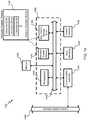
- Special-purpose computer system 1400 comprises a computer 1302, a monitor 1306 coupled to computer 1302, one or more additional user output devices 1430 (optional) coupled to computer 1302, one or more user input devices 1440 (e.g., keyboard, mouse, track ball, touch screen) coupled to computer 1302, an optional communications interface 1450 coupled to computer 1302, a computer-program product 1405 stored in a tangible computer-readable memory in computer 1302. Computer-program product 1405 directs system 1400 to perform the above-described methods.
- Computer 1302 may include one or more processors 1460 that communicate with a number of peripheral devices via a bus subsystem 1490.
- peripheral devices may include user output device(s) 1430, user input device(s) 1440, communications interface 1450, and a storage subsystem, such as random access memory (RAM) 1470 and non-volatile storage drive 1480 (e.g., disk drive, optical drive, solid state drive), which are forms of tangible computer-readable memory.
- RAM random access memory
- non-volatile storage drive 1480 e.g., disk drive, optical drive, solid state drive
- Computer-program product 1405 may be stored in non-volatile storage drive 1480 or another computer-readable medium accessible to computer 1302 and loaded into memory 1470.
- Each processor 1460 may comprise a microprocessor, such as a microprocessor from Intel® or Advanced Micro Devices, Inc.®, or the like.
- the computer 1302 runs an operating system that handles the communications of product 1405 with the above-noted components, as well as the communications between the above-noted components in support of the computer-program product 1405.
- Exemplary operating systems include Windows® or the like from Microsoft Corporation, Solaris® from Sun Microsystems, LINUX, UNIX, and the like.
- User input devices 1440 include all possible types of devices and mechanisms to input information to computer 1302. These may include a keyboard, a keypad, a mouse, a scanner, a digital drawing pad, a touch screen incorporated into the display, audio input devices such as voice recognition systems, microphones, and other types of input devices.
- user input devices 1440 are typically embodied as a computer mouse, a trackball, a track pad, a joystick, wireless remote, a drawing tablet, a voice command system.
- User input devices 1440 typically allow a user to select objects, icons, text and the like that appear on the monitor 1306 via a command such as a click of a button or the like.
- User output devices 1430 include all possible types of devices and mechanisms to output information from computer 1302. These may include a display ( e.g ., monitor 1306), printers, non-visual displays such as audio output devices, etc.
- Communications interface 1450 provides an interface to other communication networks and devices and may serve as an interface to receive data from and transmit data to other systems, WANs and/or the Internet 1318.
- Embodiments of communications interface 1450 typically include an Ethernet card, a modem (telephone, satellite, cable, ISDN), a (asynchronous) digital subscriber line (DSL) unit, a FireWire® interface, a USB® interface, a wireless network adapter, and the like.
- communications interface 1450 may be coupled to a computer network, to a FireWire® bus, or the like.
- communications interface 1450 may be physically integrated on the motherboard of computer 1302, and/or may be a software program, or the like.
- RAM 1470 and non-volatile storage drive 1480 are examples of tangible computer-readable media configured to store data such as computer-program product embodiments of the present invention, including executable computer code, human-readable code, or the like.
- Other types of tangible computer-readable media include floppy disks, removable hard disks, optical storage media such as CD-ROMs, DVDs, bar codes, semiconductor memories such as flash memories, read-only-memories (ROMs), battery-backed volatile memories, networked storage devices, and the like.
- RAM 1470 and non-volatile storage drive 1480 may be configured to store the basic programming and data constructs that provide the functionality of various embodiments of the present invention, as described above.
- RAM 1470 and non-volatile storage drive 1480 may be stored in RAM 1470 and non-volatile storage drive 1480. These instruction sets or code may be executed by the processor(s) 1460.
- RAM 1470 and non-volatile storage drive 1480 may also provide a repository to store data and data structures used in accordance with the present invention.
- RAM 1470 and non-volatile storage drive 1480 may include a number of memories including a main random access memory (RAM) to store of instructions and data during program execution and a read-only memory (ROM) in which fixed instructions are stored.
- RAM 1470 and non-volatile storage drive 1480 may include a file storage subsystem providing persistent (non-volatile) storage of program and/or data files.
- RAM 1470 and non-volatile storage drive 1480 may also include removable storage systems, such as removable flash memory.
- Bus subsystem 1490 provides a mechanism to allow the various components and subsystems of computer 1302 communicate with each other as intended. Although bus subsystem 1490 is shown schematically as a single bus, alternative embodiments of the bus subsystem 1490 may utilize multiple busses or communication paths within the computer 1302.
- Implementation of the techniques, blocks, steps and means described above may be done in various ways. For example, these techniques, blocks, steps and means may be implemented in hardware, software, or a combination thereof.
- the processing units may be implemented within one or more application specific integrated circuits (ASICs), digital signal processors (DSPs), digital signal processing devices (DSPDs), programmable logic devices (PLDs), field programmable gate arrays (FPGAs), processors, controllers, micro-controllers, microprocessors, other electronic units designed to perform the functions described above, and/or a combination thereof.
- ASICs application specific integrated circuits
- DSPs digital signal processors
- DSPDs digital signal processing devices
- PLDs programmable logic devices
- FPGAs field programmable gate arrays
- processors controllers, micro-controllers, microprocessors, other electronic units designed to perform the functions described above, and/or a combination thereof.
- the embodiments may be described as a process which is depicted as a flowchart, a flow diagram, a data flow diagram, a structure diagram, or a block diagram. Although a flowchart may describe the operations as a sequential process, many of the operations can be performed in parallel or concurrently. In addition, the order of the operations may be re-arranged.
- a process is terminated when its operations are completed, but could have additional steps not included in the figure.
- a process may correspond to a method, a function, a procedure, a subroutine, a subprogram, etc. When a process corresponds to a function, its termination corresponds to a return of the function to the calling function or the main function.
- embodiments may be implemented by hardware, software, scripting languages, firmware, middleware, microcode, hardware description languages, and/or any combination thereof.
- the program code or code segments to perform the necessary tasks may be stored in a machine readable medium such as a storage medium.
- a code segment or machine-executable instruction may represent a procedure, a function, a subprogram, a program, a routine, a subroutine, a module, a software package, a script, a class, or any combination of instructions, data structures, and/or program statements.
- a code segment may be coupled to another code segment or a hardware circuit by passing and/or receiving information, data, arguments, parameters, and/or memory contents. Information, arguments, parameters, data, etc. may be passed, forwarded, or transmitted via any suitable means including memory sharing, message passing, token passing, network transmission, etc.
- the methodologies may be implemented with modules (e.g., procedures, functions, and so on) that perform the functions described herein.
- Any machine-readable medium tangibly embodying instructions may be used in implementing the methodologies described herein.
- software codes may be stored in a memory.
- Memory may be implemented within the processor or external to the processor.
- the term "memory" refers to any type of long term, short term, volatile, nonvolatile, or other storage medium and is not to be limited to any particular type of memory or number of memories, or type of media upon which memory is stored.
- the term “storage medium” may represent one or more memories for storing data, including read only memory (ROM), random access memory (RAM), magnetic RAM, core memory, magnetic disk storage mediums, optical storage mediums, flash memory devices and/or other machine readable mediums for storing information.
- ROM read only memory
- RAM random access memory
- magnetic RAM magnetic RAM
- core memory magnetic disk storage mediums
- optical storage mediums flash memory devices and/or other machine readable mediums for storing information.
- machine-readable medium includes, but is not limited to portable or fixed storage devices, optical storage devices, wireless channels, and/or various other storage mediums capable of storing that include or carry instruction(s) and/or data.
- steps in a processes can be interchanged and/or added to each other.
- using different patch sizes can be used to detect targets, other than tools.
- images could be processed to detect that correct parts are being installed correctly, such as for aircraft manufacturing and/or maintenance.
- similar approaches can be used in convolution networks, residual networks, and other networks, not just computer neural networks.
- the embodiments may be described as a process which is depicted as a flowchart, a flow diagram, a data flow diagram, a structure diagram, or a block diagram. Although a flowchart may describe the operations as a sequential process, many of the operations can be performed in parallel or concurrently. In addition, the order of the operations may be re-arranged. A process is terminated when its operations are completed, but could have additional steps not included in the figure. A process may correspond to a method, a function, a procedure, a subroutine, a subprogram, etc.
Landscapes
- Engineering & Computer Science (AREA)
- Theoretical Computer Science (AREA)
- General Physics & Mathematics (AREA)
- Physics & Mathematics (AREA)
- Computer Vision & Pattern Recognition (AREA)
- Multimedia (AREA)
- Evolutionary Computation (AREA)
- Artificial Intelligence (AREA)
- Health & Medical Sciences (AREA)
- General Health & Medical Sciences (AREA)
- Databases & Information Systems (AREA)
- Software Systems (AREA)
- Medical Informatics (AREA)
- Computing Systems (AREA)
- Life Sciences & Earth Sciences (AREA)
- Mechanical Engineering (AREA)
- Biodiversity & Conservation Biology (AREA)
- Biomedical Technology (AREA)
- Molecular Biology (AREA)
- Data Mining & Analysis (AREA)
- Bioinformatics & Computational Biology (AREA)
- Evolutionary Biology (AREA)
- General Engineering & Computer Science (AREA)
- Bioinformatics & Cheminformatics (AREA)
- Image Analysis (AREA)
Claims (14)
- System zum Erkennen eines Tools in einer Szene, wobei das System umfasst:eine Kameraeinheit (108) zum Aufnehmen eines Bilds der Szene; undeinen oder mehrere Prozessoren, welche konfiguriert sind zum:Aufteilen des Bilds in eine erste Anzahl an Patches, um eine erste Gruppe von Patches (908-1) zu erzeugen, wobei ein Patch ein Bereich des Bilds ist,Durchführen einer Objekterkennung an der ersten Gruppe von Patches, um das Tool in einem Patch der ersten Gruppe von Patches zu identifizieren,Bestimmen, dass das Tool in der ersten Gruppe von Patches nicht erkannt worden ist,Aufteilen des Bilds in eine zweite Anzahl an Patches, um eine zweite Gruppe von Patches (908-2) zu erzeugen, nach dem Bestimmen, dass das Tool in der ersten Gruppe von Patches nicht erkannt worden ist,Durchführen einer Objekterkennung an der zweiten Gruppe von Patches, um das Tool in einem Patch der zweiten Gruppe von Patches zu identifizieren, undBestimmen, dass das Tool in einem Patch der zweiten Gruppe von Patches erkannt worden ist,wobei der eine oder die mehreren Prozessoren ferner konfiguriert sind zumTrainieren eines neuronalen Computernetzwerks, das Werkzeug zu identifizieren, bevor das Bild der Szene aufgenommen wird; undwobei das neuronale Computernetzwerk auf einem Maßstab trainiert wird und der Maßstab benutzt wird zum:Durchführen der Objekterkennung an der ersten Gruppe von Patches, undDurchführen der Objekterkennung an der zweiten Gruppe von Patches.
- System nach Anspruch 1, wobei die Kameraeinheit eine erste Kameraeinheit ist, der eine oder die mehreren Prozessoren eine erste Prozessoreinheit sind, das Bild ein erstes Bild ist und das System ferner umfasst:eine zweite Kameraeinheit, welche dafür konfiguriert ist, ein zweites Bild aufzunehmen, undeine zweite Prozessoreinheit, welche dafür konfiguriert ist, eine Position des Tools in drei Dimensionen zu bestimmen, basierend auf dem ersten Bild und dem zweiten Bild.
- System nach Anspruch 1 oder 2, ferner umfassend ein Display, wobei der eine oder die mehreren Prozessoren ferner dafür konfiguriert sind, ein Zeichen für das Tool anzuzeigen, welches über ein Bild auf dem Display gelegt ist;
und wobei das Zeichen für das Tool gegebenenfalls eine Heatmap ist. - Verfahren zum Erkennen eines Tools in einer Szene, wobei das Verfahren umfasst:Aufnehmen eines Bilds der Szene;Aufteilen des Bilds in eine erste Anzahl an Patches, um eine erste Gruppe von Patches zu erzeugen, wobei ein Patch ein Bereich des Bilds ist;Durchführen einer Objekterkennung an der ersten Gruppe von Patches, um das Tool in einem Patch der ersten Gruppe von Patches zu identifizieren;Bestimmen, dass das Tool in der ersten Gruppe von Patches nicht erkannt worden ist;Aufteilen des Bilds in eine zweite Anzahl an Patches, um eine zweite Gruppe von Patches zu erzeugen, nach dem Bestimmen, dass das Tool in der ersten Gruppe von Patches nicht erkannt worden ist;Durchführen einer Objekterkennung an der zweiten Gruppe von Patches, um das Tool in einem Patch der zweiten Gruppe von Patches zu identifizieren; undBestimmen, dass das Tool in einem Patch der zweiten Gruppe von Patches erkannt worden ist;Trainieren eines neuronalen Computernetzwerks, das Werkzeug zu identifizieren, bevor das Bild der Szene aufgenommen wird;wobei das neuronale Computernetzwerk auf einem Maßstab trainiert wird und der Maßstab benutzt wird zum:Durchführen der Objekterkennung an der ersten Gruppe von Patches, undDurchführen der Objekterkennung an der zweiten Gruppe von Patches.
- Verfahren nach Anspruch 4, wobei die erste Anzahl an Patches niedriger als die zweite Anzahl an Patches ist.
- Verfahren nach Anspruch 4 oder 5, ferner umfassend:Aufteilen des Bilds in eine dritte Anzahl an Patches, um eine dritte Gruppe von Patches zu erzeugen, nach dem Bestimmen, dass das Tool in der ersten Gruppe von Patches nicht erkannt worden ist, und vor dem Aufteilen des Bilds in eine zweite Anzahl an Patches; undDurchführen einer Objekterkennung an der dritten Gruppe von Patches, um das Tool in einem Patch der dritten Gruppe von Patches zu identifizieren; undBestimmen, dass das Tool in der dritten Gruppe von Patches nicht erkannt worden ist;und wobei gegebenenfalls die dritte Anzahl an Patches höher als die erste Anzahl an Patches und niedriger als die zweite Anzahl an Patches ist.
- Verfahren nach einem der Ansprüche 4 bis 6, wobei das Durchführen der Objekterkennung umfasst:Aufteilen eines Patch in eine Anzahl an Zellen; undBerechnen einer Wahrscheinlichkeit, dass sich ein Teil des Tools in einer Zelle befindet.
- Verfahren nach einem der Ansprüche 4 bis 7, wobei die Patches der ersten Gruppe von Patches und/oder der zweiten Gruppe von Patches rechteckig sind.
- Verfahren nach einem der Ansprüche 4 bis 8, wobei die Patches der ersten Gruppe von Patches die gleiche Größe aufweisen;
oder wobei ein erstes Patch der ersten Gruppe von Patches nicht die gleiche Größe wie ein zweites Patch der ersten Gruppe von Patches aufweist. - Verfahren nach einem der Ansprüche 4 bis 9, ferner umfassend das Berechnen einer dreidimensionalen Position des Tools basierend auf dem Bild von einer ersten Kameraeinheit, wobei das Bild ein erstes Bild ist, und einem zweiten Bild von einer zweiten Kameraeinheit.
- Verfahren nach einem der Ansprüche 4 bis 10, wobei das Tool ein erstes Tool ist und das Verfahren ferner das Erkennen eines zweiten Tools in der ersten Gruppe von Patches umfasst.
- Verfahren nach einem der Ansprüche 4 bis 11, ferner umfassend das Bestimmen, das Bild nicht in eine dritte Anzahl an Patches aufzuteilen, basierend auf der Bestimmung, dass das Tool in einem Patch der zweiten Gruppe von Patches erkannt worden ist, wobei die dritte Anzahl an Patches höher als die zweite Anzahl an Patches ist.
- Verfahren nach einem der Ansprüche 4 bis 12, ferner umfassend das Aufnehmen des Bilds der Szene unter Verwendung einer Kameraeinheit, welche zwei oder mehr Bildsensoren aufweist.
- Speichervorrichtung, welche Befehle umfasst, die bewirken, dass ein oder mehrere Prozessoren das Verfahren nach einem der Ansprüche 4 bis 13 ausführen.
Applications Claiming Priority (1)
| Application Number | Priority Date | Filing Date | Title |
|---|---|---|---|
| US15/689,514 US10339670B2 (en) | 2017-08-29 | 2017-08-29 | 3D tool tracking and positioning using cameras |
Publications (2)
| Publication Number | Publication Date |
|---|---|
| EP3459682A1 EP3459682A1 (de) | 2019-03-27 |
| EP3459682B1 true EP3459682B1 (de) | 2021-06-09 |
Family
ID=63442454
Family Applications (1)
| Application Number | Title | Priority Date | Filing Date |
|---|---|---|---|
| EP18191145.4A Active EP3459682B1 (de) | 2017-08-29 | 2018-08-28 | 3d-tool-verfolgung und -positionierung mithilfe von kameras |
Country Status (2)
| Country | Link |
|---|---|
| US (1) | US10339670B2 (de) |
| EP (1) | EP3459682B1 (de) |
Families Citing this family (7)
| Publication number | Priority date | Publication date | Assignee | Title |
|---|---|---|---|---|
| US10823815B2 (en) * | 2018-02-28 | 2020-11-03 | The Boeing Company | Hybrid position locating system in a manufacturing environment |
| KR102051032B1 (ko) * | 2018-08-01 | 2019-12-02 | 경북대학교 산학협력단 | 객체 탐지 장치 및 제어 방법 |
| WO2020092497A2 (en) | 2018-10-31 | 2020-05-07 | Milwaukee Electric Tool Corporation | Spatially-aware tool system |
| US11170538B2 (en) | 2018-10-31 | 2021-11-09 | Milwaukee Electric Tool Corporation | Spatially-aware tool system |
| CN109948690A (zh) * | 2019-03-14 | 2019-06-28 | 西南交通大学 | 一种基于深度学习和结构信息的高铁场景感知方法 |
| CN110008141B (zh) * | 2019-03-28 | 2023-02-24 | 维沃移动通信有限公司 | 一种碎片整理方法和电子设备 |
| CN113103068B (zh) * | 2021-04-19 | 2022-03-29 | 大连理工大学 | 一种基于深度迁移学习的刀具状态监测方法 |
Family Cites Families (41)
| Publication number | Priority date | Publication date | Assignee | Title |
|---|---|---|---|---|
| US2685082A (en) | 1951-03-28 | 1954-07-27 | Telecomputing Corp | Position indicating device |
| US2966090A (en) | 1954-12-28 | 1960-12-27 | Gasaccumulator Svenska Ab | Optical distance measuring device |
| FR2630538A1 (fr) | 1988-04-22 | 1989-10-27 | Image Technologie | Procede, dispositif et camera video pour mesurer des longueurs en utilisant des images video |
| US6064398A (en) | 1993-09-10 | 2000-05-16 | Geovector Corporation | Electro-optic vision systems |
| US5926260A (en) | 1995-01-19 | 1999-07-20 | Laser Technology, Inc. | Compact laser-based distance measuring apparatus |
| US6097429A (en) * | 1997-08-01 | 2000-08-01 | Esco Electronics Corporation | Site control unit for video security system |
| US6919880B2 (en) | 2001-06-01 | 2005-07-19 | Smart Technologies Inc. | Calibrating camera offsets to facilitate object position determination using triangulation |
| AU2003226047A1 (en) | 2002-04-10 | 2003-10-27 | Pan-X Imaging, Inc. | A digital imaging system |
| KR100556612B1 (ko) | 2002-06-29 | 2006-03-06 | 삼성전자주식회사 | 레이저를 이용한 위치 측정 장치 및 방법 |
| US7180014B2 (en) * | 2003-03-20 | 2007-02-20 | Boris Farber | Method and equipment for automated tracking and identification of nonuniform items |
| FI115414B (fi) | 2003-07-03 | 2005-04-29 | Sandvik Tamrock Oy | Järjestely kaivosajoneuvon sijainnin valvontaan kaivoksessa |
| US20060174302A1 (en) * | 2005-02-01 | 2006-08-03 | Bryan Mattern | Automated remote monitoring system for construction sites |
| WO2006099059A2 (en) | 2005-03-10 | 2006-09-21 | Witten Technologies, Inc. | Method for correcting a 3d location measured by a tracking system assuming a vertical offset |
| US8073528B2 (en) * | 2007-09-30 | 2011-12-06 | Intuitive Surgical Operations, Inc. | Tool tracking systems, methods and computer products for image guided surgery |
| US8147503B2 (en) * | 2007-09-30 | 2012-04-03 | Intuitive Surgical Operations Inc. | Methods of locating and tracking robotic instruments in robotic surgical systems |
| US7552467B2 (en) * | 2006-04-24 | 2009-06-23 | Jeffrey Dean Lindsay | Security systems for protecting an asset |
| GB2459602B (en) | 2007-02-21 | 2011-09-21 | Pixel Velocity Inc | Scalable system for wide area surveillance |
| US9968256B2 (en) * | 2007-03-08 | 2018-05-15 | Sync-Rx Ltd. | Automatic identification of a tool |
| US7949150B2 (en) * | 2007-04-02 | 2011-05-24 | Objectvideo, Inc. | Automatic camera calibration and geo-registration using objects that provide positional information |
| US8356249B2 (en) * | 2007-05-22 | 2013-01-15 | Vidsys, Inc. | Intelligent video tours |
| US8331730B2 (en) | 2008-04-01 | 2012-12-11 | Hewlett-Packard Development Company, L.P. | Systems and methods to increase speed of object detection in a digital image |
| EP2116919A1 (de) | 2008-05-09 | 2009-11-11 | MBDA UK Limited | Anzeige für dreidimensionale Objekte |
| US8848974B2 (en) * | 2008-09-29 | 2014-09-30 | Restoration Robotics, Inc. | Object-tracking systems and methods |
| US8385599B2 (en) | 2008-10-10 | 2013-02-26 | Sri International | System and method of detecting objects |
| JP5624615B2 (ja) | 2009-06-23 | 2014-11-12 | ライカ・ジオシステムズ・アクチェンゲゼルシャフトLeica Geosystems Ag | 追跡方法、および、レーザートラッカを有する測定システム |
| US20110115909A1 (en) * | 2009-11-13 | 2011-05-19 | Sternberg Stanley R | Method for tracking an object through an environment across multiple cameras |
| DE102009058802B4 (de) | 2009-12-18 | 2018-03-29 | Airbus Operations Gmbh | Anordnung zur kombinierten Darstellung eines realen und eines virtuellen Modells |
| ES2817800T3 (es) | 2010-04-22 | 2021-04-08 | Metronor As | Sistema de medición óptica |
| US9064172B2 (en) * | 2010-10-05 | 2015-06-23 | Utc Fire & Security Corporation | System and method for object detection |
| CN102329806B (zh) * | 2011-09-30 | 2014-10-15 | 中国科学院遗传与发育生物学研究所 | 控制水稻粒宽、粒重和产量的基因及其应用 |
| US8930009B2 (en) * | 2011-10-20 | 2015-01-06 | Kabushiki Kaisha Yaskawa Denki | Robot system and processed object manufacturing method |
| US9228833B2 (en) | 2012-06-28 | 2016-01-05 | GM Global Technology Operations LLC | Wide baseline binocular object matching method using minimal cost flow network |
| US9706264B2 (en) | 2013-02-06 | 2017-07-11 | Robert Bosch Gmbh | Multiple field-of-view video streaming |
| US9687950B2 (en) | 2013-03-13 | 2017-06-27 | Trimble Inc. | System and method for positioning a tool in a work space |
| KR101622748B1 (ko) | 2014-03-31 | 2016-05-20 | 한국과학기술원 | 입력 이미지로부터 객체를 검출하기 위한 방법, 장치 및 컴퓨터 판독가능 기록매체 |
| US9305216B1 (en) * | 2014-12-15 | 2016-04-05 | Amazon Technologies, Inc. | Context-based detection and classification of actions |
| US10147236B2 (en) * | 2014-12-15 | 2018-12-04 | Autodesk, Inc. | Smart tools and workspaces for do-it-yourself tasks |
| WO2016100816A1 (en) | 2014-12-19 | 2016-06-23 | United Technologies Corporation | Sensor data fusion for prognostics and health monitoring |
| US9536176B2 (en) * | 2015-03-23 | 2017-01-03 | International Business Machines Corporation | Environmental-based location monitoring |
| US9652896B1 (en) * | 2015-10-30 | 2017-05-16 | Snap Inc. | Image based tracking in augmented reality systems |
| US10061323B2 (en) * | 2016-12-22 | 2018-08-28 | Advanced Construction Robotics, Inc. | Autonomous apparatus and system for repetitive tasks in construction project |
-
2017
- 2017-08-29 US US15/689,514 patent/US10339670B2/en active Active
-
2018
- 2018-08-28 EP EP18191145.4A patent/EP3459682B1/de active Active
Non-Patent Citations (1)
| Title |
|---|
| None * |
Also Published As
| Publication number | Publication date |
|---|---|
| US10339670B2 (en) | 2019-07-02 |
| US20190066331A1 (en) | 2019-02-28 |
| EP3459682A1 (de) | 2019-03-27 |
Similar Documents
| Publication | Publication Date | Title |
|---|---|---|
| US10339670B2 (en) | 3D tool tracking and positioning using cameras | |
| CN111352434B (zh) | 支持接近机场的机场跑道的飞机的设备及方法 | |
| EP3631360B1 (de) | Infrastrukturpositionierendes kamerasystem | |
| EP3444784B1 (de) | Selbstpositionierendes kamerasystem zum 3d-cad/bim-modell | |
| US20230113831A1 (en) | Monitoring construction of a structure | |
| US10646975B2 (en) | Measurement, layout, marking, firestop stick | |
| US10026227B2 (en) | Portable augmented reality | |
| US20180339386A1 (en) | Calibration approach for camera placement | |
| EP2972084B1 (de) | System und verfahren zur positionierung eines werkzeugs in einem arbeitsraum | |
| Tuttas et al. | Validation of BIM components by photogrammetric point clouds for construction site monitoring | |
| JP7113611B2 (ja) | 位置特定装置、位置特定プログラム及び位置特定方法、並びに、撮影画像登録装置、撮影画像登録プログラム及び撮影画像登録方法 | |
| CN111988524A (zh) | 一种无人机与摄像头协同避障方法、服务器及存储介质 | |
| US9854148B2 (en) | Micro-location of devices within a wireless network using room boundary images | |
| US10997747B2 (en) | Target positioning with bundle adjustment | |
| JP7097207B2 (ja) | 建造物管理システム、学習装置、位置判定装置、及び位置判定方法 | |
| KR102099286B1 (ko) | 실내 전기 설비를 설계 및 시공하기 위한 제어 방법 및 장치 | |
| WO2025034910A1 (en) | Computer vision classifier defined path planning for unmanned aerial vehicles | |
| CN114510035A (zh) | 机器人远程工勘方法、装置及存储介质 | |
| CN110906922A (zh) | 无人机位姿信息的确定方法及装置、存储介质、终端 | |
| Hussain et al. | A Dynamic Architecture to Control Multi-Rotors Using Hand Gestures | |
| Worcester | Machine vision and learning for an autonomous control system | |
| Altakrouri | Automated Building Inspection System | |
| Fernando | Image-Based Structural Analysis Using Computer Vision and LLMs: PhotoBeamSolver | |
| JP2024022449A (ja) | 情報処理システム及びプログラム、情報処理方法、サーバ | |
| WO2025015113A1 (en) | Point of interest tracking and estimation |
Legal Events
| Date | Code | Title | Description |
|---|---|---|---|
| PUAI | Public reference made under article 153(3) epc to a published international application that has entered the european phase |
Free format text: ORIGINAL CODE: 0009012 |
|
| STAA | Information on the status of an ep patent application or granted ep patent |
Free format text: STATUS: THE APPLICATION HAS BEEN PUBLISHED |
|
| AK | Designated contracting states |
Kind code of ref document: A1 Designated state(s): AL AT BE BG CH CY CZ DE DK EE ES FI FR GB GR HR HU IE IS IT LI LT LU LV MC MK MT NL NO PL PT RO RS SE SI SK SM TR |
|
| AX | Request for extension of the european patent |
Extension state: BA ME |
|
| STAA | Information on the status of an ep patent application or granted ep patent |
Free format text: STATUS: REQUEST FOR EXAMINATION WAS MADE |
|
| 17P | Request for examination filed |
Effective date: 20190923 |
|
| RBV | Designated contracting states (corrected) |
Designated state(s): AL AT BE BG CH CY CZ DE DK EE ES FI FR GB GR HR HU IE IS IT LI LT LU LV MC MK MT NL NO PL PT RO RS SE SI SK SM TR |
|
| RIC1 | Information provided on ipc code assigned before grant |
Ipc: G06K 9/46 20060101ALI20201116BHEP Ipc: G06T 7/70 20170101ALI20201116BHEP Ipc: G06K 9/62 20060101ALI20201116BHEP Ipc: G06K 9/00 20060101ALI20201116BHEP Ipc: B25F 5/00 20060101AFI20201116BHEP |
|
| GRAP | Despatch of communication of intention to grant a patent |
Free format text: ORIGINAL CODE: EPIDOSNIGR1 |
|
| STAA | Information on the status of an ep patent application or granted ep patent |
Free format text: STATUS: GRANT OF PATENT IS INTENDED |
|
| INTG | Intention to grant announced |
Effective date: 20210118 |
|
| GRAS | Grant fee paid |
Free format text: ORIGINAL CODE: EPIDOSNIGR3 |
|
| GRAA | (expected) grant |
Free format text: ORIGINAL CODE: 0009210 |
|
| STAA | Information on the status of an ep patent application or granted ep patent |
Free format text: STATUS: THE PATENT HAS BEEN GRANTED |
|
| AK | Designated contracting states |
Kind code of ref document: B1 Designated state(s): AL AT BE BG CH CY CZ DE DK EE ES FI FR GB GR HR HU IE IS IT LI LT LU LV MC MK MT NL NO PL PT RO RS SE SI SK SM TR |
|
| REG | Reference to a national code |
Ref country code: GB Ref legal event code: FG4D |
|
| REG | Reference to a national code |
Ref country code: CH Ref legal event code: EP Ref country code: AT Ref legal event code: REF Ref document number: 1400067 Country of ref document: AT Kind code of ref document: T Effective date: 20210615 |
|
| REG | Reference to a national code |
Ref country code: DE Ref legal event code: R096 Ref document number: 602018018278 Country of ref document: DE |
|
| REG | Reference to a national code |
Ref country code: IE Ref legal event code: FG4D |
|
| REG | Reference to a national code |
Ref country code: LT Ref legal event code: MG9D |
|
| PG25 | Lapsed in a contracting state [announced via postgrant information from national office to epo] |
Ref country code: FI Free format text: LAPSE BECAUSE OF FAILURE TO SUBMIT A TRANSLATION OF THE DESCRIPTION OR TO PAY THE FEE WITHIN THE PRESCRIBED TIME-LIMIT Effective date: 20210609 Ref country code: HR Free format text: LAPSE BECAUSE OF FAILURE TO SUBMIT A TRANSLATION OF THE DESCRIPTION OR TO PAY THE FEE WITHIN THE PRESCRIBED TIME-LIMIT Effective date: 20210609 Ref country code: LT Free format text: LAPSE BECAUSE OF FAILURE TO SUBMIT A TRANSLATION OF THE DESCRIPTION OR TO PAY THE FEE WITHIN THE PRESCRIBED TIME-LIMIT Effective date: 20210609 Ref country code: BG Free format text: LAPSE BECAUSE OF FAILURE TO SUBMIT A TRANSLATION OF THE DESCRIPTION OR TO PAY THE FEE WITHIN THE PRESCRIBED TIME-LIMIT Effective date: 20210909 |
|
| REG | Reference to a national code |
Ref country code: AT Ref legal event code: MK05 Ref document number: 1400067 Country of ref document: AT Kind code of ref document: T Effective date: 20210609 |
|
| REG | Reference to a national code |
Ref country code: NL Ref legal event code: MP Effective date: 20210609 |
|
| PG25 | Lapsed in a contracting state [announced via postgrant information from national office to epo] |
Ref country code: LV Free format text: LAPSE BECAUSE OF FAILURE TO SUBMIT A TRANSLATION OF THE DESCRIPTION OR TO PAY THE FEE WITHIN THE PRESCRIBED TIME-LIMIT Effective date: 20210609 Ref country code: NO Free format text: LAPSE BECAUSE OF FAILURE TO SUBMIT A TRANSLATION OF THE DESCRIPTION OR TO PAY THE FEE WITHIN THE PRESCRIBED TIME-LIMIT Effective date: 20210909 Ref country code: RS Free format text: LAPSE BECAUSE OF FAILURE TO SUBMIT A TRANSLATION OF THE DESCRIPTION OR TO PAY THE FEE WITHIN THE PRESCRIBED TIME-LIMIT Effective date: 20210609 Ref country code: SE Free format text: LAPSE BECAUSE OF FAILURE TO SUBMIT A TRANSLATION OF THE DESCRIPTION OR TO PAY THE FEE WITHIN THE PRESCRIBED TIME-LIMIT Effective date: 20210609 Ref country code: GR Free format text: LAPSE BECAUSE OF FAILURE TO SUBMIT A TRANSLATION OF THE DESCRIPTION OR TO PAY THE FEE WITHIN THE PRESCRIBED TIME-LIMIT Effective date: 20210910 |
|
| PG25 | Lapsed in a contracting state [announced via postgrant information from national office to epo] |
Ref country code: SK Free format text: LAPSE BECAUSE OF FAILURE TO SUBMIT A TRANSLATION OF THE DESCRIPTION OR TO PAY THE FEE WITHIN THE PRESCRIBED TIME-LIMIT Effective date: 20210609 Ref country code: SM Free format text: LAPSE BECAUSE OF FAILURE TO SUBMIT A TRANSLATION OF THE DESCRIPTION OR TO PAY THE FEE WITHIN THE PRESCRIBED TIME-LIMIT Effective date: 20210609 Ref country code: EE Free format text: LAPSE BECAUSE OF FAILURE TO SUBMIT A TRANSLATION OF THE DESCRIPTION OR TO PAY THE FEE WITHIN THE PRESCRIBED TIME-LIMIT Effective date: 20210609 Ref country code: ES Free format text: LAPSE BECAUSE OF FAILURE TO SUBMIT A TRANSLATION OF THE DESCRIPTION OR TO PAY THE FEE WITHIN THE PRESCRIBED TIME-LIMIT Effective date: 20210609 Ref country code: CZ Free format text: LAPSE BECAUSE OF FAILURE TO SUBMIT A TRANSLATION OF THE DESCRIPTION OR TO PAY THE FEE WITHIN THE PRESCRIBED TIME-LIMIT Effective date: 20210609 Ref country code: AT Free format text: LAPSE BECAUSE OF FAILURE TO SUBMIT A TRANSLATION OF THE DESCRIPTION OR TO PAY THE FEE WITHIN THE PRESCRIBED TIME-LIMIT Effective date: 20210609 Ref country code: NL Free format text: LAPSE BECAUSE OF FAILURE TO SUBMIT A TRANSLATION OF THE DESCRIPTION OR TO PAY THE FEE WITHIN THE PRESCRIBED TIME-LIMIT Effective date: 20210609 Ref country code: RO Free format text: LAPSE BECAUSE OF FAILURE TO SUBMIT A TRANSLATION OF THE DESCRIPTION OR TO PAY THE FEE WITHIN THE PRESCRIBED TIME-LIMIT Effective date: 20210609 Ref country code: PT Free format text: LAPSE BECAUSE OF FAILURE TO SUBMIT A TRANSLATION OF THE DESCRIPTION OR TO PAY THE FEE WITHIN THE PRESCRIBED TIME-LIMIT Effective date: 20211011 |
|
| PG25 | Lapsed in a contracting state [announced via postgrant information from national office to epo] |
Ref country code: PL Free format text: LAPSE BECAUSE OF FAILURE TO SUBMIT A TRANSLATION OF THE DESCRIPTION OR TO PAY THE FEE WITHIN THE PRESCRIBED TIME-LIMIT Effective date: 20210609 |
|
| REG | Reference to a national code |
Ref country code: DE Ref legal event code: R097 Ref document number: 602018018278 Country of ref document: DE |
|
| REG | Reference to a national code |
Ref country code: CH Ref legal event code: PL |
|
| PG25 | Lapsed in a contracting state [announced via postgrant information from national office to epo] |
Ref country code: MC Free format text: LAPSE BECAUSE OF FAILURE TO SUBMIT A TRANSLATION OF THE DESCRIPTION OR TO PAY THE FEE WITHIN THE PRESCRIBED TIME-LIMIT Effective date: 20210609 |
|
| PLBE | No opposition filed within time limit |
Free format text: ORIGINAL CODE: 0009261 |
|
| STAA | Information on the status of an ep patent application or granted ep patent |
Free format text: STATUS: NO OPPOSITION FILED WITHIN TIME LIMIT |
|
| REG | Reference to a national code |
Ref country code: BE Ref legal event code: MM Effective date: 20210831 |
|
| PG25 | Lapsed in a contracting state [announced via postgrant information from national office to epo] |
Ref country code: LI Free format text: LAPSE BECAUSE OF NON-PAYMENT OF DUE FEES Effective date: 20210831 Ref country code: DK Free format text: LAPSE BECAUSE OF FAILURE TO SUBMIT A TRANSLATION OF THE DESCRIPTION OR TO PAY THE FEE WITHIN THE PRESCRIBED TIME-LIMIT Effective date: 20210609 Ref country code: CH Free format text: LAPSE BECAUSE OF NON-PAYMENT OF DUE FEES Effective date: 20210831 |
|
| 26N | No opposition filed |
Effective date: 20220310 |
|
| PG25 | Lapsed in a contracting state [announced via postgrant information from national office to epo] |
Ref country code: LU Free format text: LAPSE BECAUSE OF NON-PAYMENT OF DUE FEES Effective date: 20210828 Ref country code: AL Free format text: LAPSE BECAUSE OF FAILURE TO SUBMIT A TRANSLATION OF THE DESCRIPTION OR TO PAY THE FEE WITHIN THE PRESCRIBED TIME-LIMIT Effective date: 20210609 |
|
| PG25 | Lapsed in a contracting state [announced via postgrant information from national office to epo] |
Ref country code: IT Free format text: LAPSE BECAUSE OF FAILURE TO SUBMIT A TRANSLATION OF THE DESCRIPTION OR TO PAY THE FEE WITHIN THE PRESCRIBED TIME-LIMIT Effective date: 20210609 Ref country code: IE Free format text: LAPSE BECAUSE OF NON-PAYMENT OF DUE FEES Effective date: 20210828 Ref country code: BE Free format text: LAPSE BECAUSE OF NON-PAYMENT OF DUE FEES Effective date: 20210831 |
|
| PG25 | Lapsed in a contracting state [announced via postgrant information from national office to epo] |
Ref country code: CY Free format text: LAPSE BECAUSE OF FAILURE TO SUBMIT A TRANSLATION OF THE DESCRIPTION OR TO PAY THE FEE WITHIN THE PRESCRIBED TIME-LIMIT Effective date: 20210609 |
|
| PG25 | Lapsed in a contracting state [announced via postgrant information from national office to epo] |
Ref country code: HU Free format text: LAPSE BECAUSE OF FAILURE TO SUBMIT A TRANSLATION OF THE DESCRIPTION OR TO PAY THE FEE WITHIN THE PRESCRIBED TIME-LIMIT; INVALID AB INITIO Effective date: 20180828 |
|
| PG25 | Lapsed in a contracting state [announced via postgrant information from national office to epo] |
Ref country code: MK Free format text: LAPSE BECAUSE OF FAILURE TO SUBMIT A TRANSLATION OF THE DESCRIPTION OR TO PAY THE FEE WITHIN THE PRESCRIBED TIME-LIMIT Effective date: 20210609 |
|
| PG25 | Lapsed in a contracting state [announced via postgrant information from national office to epo] |
Ref country code: MT Free format text: LAPSE BECAUSE OF FAILURE TO SUBMIT A TRANSLATION OF THE DESCRIPTION OR TO PAY THE FEE WITHIN THE PRESCRIBED TIME-LIMIT Effective date: 20210609 |
|
| PGFP | Annual fee paid to national office [announced via postgrant information from national office to epo] |
Ref country code: DE Payment date: 20250827 Year of fee payment: 8 |
|
| PGFP | Annual fee paid to national office [announced via postgrant information from national office to epo] |
Ref country code: GB Payment date: 20250826 Year of fee payment: 8 |
|
| PGFP | Annual fee paid to national office [announced via postgrant information from national office to epo] |
Ref country code: FR Payment date: 20250825 Year of fee payment: 8 |
|
| PG25 | Lapsed in a contracting state [announced via postgrant information from national office to epo] |
Ref country code: TR Free format text: LAPSE BECAUSE OF FAILURE TO SUBMIT A TRANSLATION OF THE DESCRIPTION OR TO PAY THE FEE WITHIN THE PRESCRIBED TIME-LIMIT Effective date: 20210609 |