EP3459673A1 - Additive manufacturing in situ stress relief - Google Patents
Additive manufacturing in situ stress relief Download PDFInfo
- Publication number
- EP3459673A1 EP3459673A1 EP18196692.0A EP18196692A EP3459673A1 EP 3459673 A1 EP3459673 A1 EP 3459673A1 EP 18196692 A EP18196692 A EP 18196692A EP 3459673 A1 EP3459673 A1 EP 3459673A1
- Authority
- EP
- European Patent Office
- Prior art keywords
- workpiece
- build plate
- recited
- melt pool
- temperature
- Prior art date
- Legal status (The legal status is an assumption and is not a legal conclusion. Google has not performed a legal analysis and makes no representation as to the accuracy of the status listed.)
- Granted
Links
Images


Classifications
-
- B—PERFORMING OPERATIONS; TRANSPORTING
- B23—MACHINE TOOLS; METAL-WORKING NOT OTHERWISE PROVIDED FOR
- B23K—SOLDERING OR UNSOLDERING; WELDING; CLADDING OR PLATING BY SOLDERING OR WELDING; CUTTING BY APPLYING HEAT LOCALLY, e.g. FLAME CUTTING; WORKING BY LASER BEAM
- B23K26/00—Working by laser beam, e.g. welding, cutting or boring
- B23K26/34—Laser welding for purposes other than joining
- B23K26/342—Build-up welding
-
- B—PERFORMING OPERATIONS; TRANSPORTING
- B22—CASTING; POWDER METALLURGY
- B22F—WORKING METALLIC POWDER; MANUFACTURE OF ARTICLES FROM METALLIC POWDER; MAKING METALLIC POWDER; APPARATUS OR DEVICES SPECIALLY ADAPTED FOR METALLIC POWDER
- B22F10/00—Additive manufacturing of workpieces or articles from metallic powder
-
- B—PERFORMING OPERATIONS; TRANSPORTING
- B22—CASTING; POWDER METALLURGY
- B22F—WORKING METALLIC POWDER; MANUFACTURE OF ARTICLES FROM METALLIC POWDER; MAKING METALLIC POWDER; APPARATUS OR DEVICES SPECIALLY ADAPTED FOR METALLIC POWDER
- B22F10/00—Additive manufacturing of workpieces or articles from metallic powder
- B22F10/20—Direct sintering or melting
- B22F10/25—Direct deposition of metal particles, e.g. direct metal deposition [DMD] or laser engineered net shaping [LENS]
-
- B—PERFORMING OPERATIONS; TRANSPORTING
- B22—CASTING; POWDER METALLURGY
- B22F—WORKING METALLIC POWDER; MANUFACTURE OF ARTICLES FROM METALLIC POWDER; MAKING METALLIC POWDER; APPARATUS OR DEVICES SPECIALLY ADAPTED FOR METALLIC POWDER
- B22F12/00—Apparatus or devices specially adapted for additive manufacturing; Auxiliary means for additive manufacturing; Combinations of additive manufacturing apparatus or devices with other processing apparatus or devices
- B22F12/10—Auxiliary heating means
-
- B—PERFORMING OPERATIONS; TRANSPORTING
- B22—CASTING; POWDER METALLURGY
- B22F—WORKING METALLIC POWDER; MANUFACTURE OF ARTICLES FROM METALLIC POWDER; MAKING METALLIC POWDER; APPARATUS OR DEVICES SPECIALLY ADAPTED FOR METALLIC POWDER
- B22F12/00—Apparatus or devices specially adapted for additive manufacturing; Auxiliary means for additive manufacturing; Combinations of additive manufacturing apparatus or devices with other processing apparatus or devices
- B22F12/30—Platforms or substrates
-
- B—PERFORMING OPERATIONS; TRANSPORTING
- B22—CASTING; POWDER METALLURGY
- B22F—WORKING METALLIC POWDER; MANUFACTURE OF ARTICLES FROM METALLIC POWDER; MAKING METALLIC POWDER; APPARATUS OR DEVICES SPECIALLY ADAPTED FOR METALLIC POWDER
- B22F12/00—Apparatus or devices specially adapted for additive manufacturing; Auxiliary means for additive manufacturing; Combinations of additive manufacturing apparatus or devices with other processing apparatus or devices
- B22F12/90—Means for process control, e.g. cameras or sensors
-
- B—PERFORMING OPERATIONS; TRANSPORTING
- B23—MACHINE TOOLS; METAL-WORKING NOT OTHERWISE PROVIDED FOR
- B23K—SOLDERING OR UNSOLDERING; WELDING; CLADDING OR PLATING BY SOLDERING OR WELDING; CUTTING BY APPLYING HEAT LOCALLY, e.g. FLAME CUTTING; WORKING BY LASER BEAM
- B23K15/00—Electron-beam welding or cutting
- B23K15/0046—Welding
- B23K15/0086—Welding welding for purposes other than joining, e.g. build-up welding
-
- B—PERFORMING OPERATIONS; TRANSPORTING
- B23—MACHINE TOOLS; METAL-WORKING NOT OTHERWISE PROVIDED FOR
- B23K—SOLDERING OR UNSOLDERING; WELDING; CLADDING OR PLATING BY SOLDERING OR WELDING; CUTTING BY APPLYING HEAT LOCALLY, e.g. FLAME CUTTING; WORKING BY LASER BEAM
- B23K26/00—Working by laser beam, e.g. welding, cutting or boring
- B23K26/02—Positioning or observing the workpiece, e.g. with respect to the point of impact; Aligning, aiming or focusing the laser beam
- B23K26/03—Observing, e.g. monitoring, the workpiece
- B23K26/034—Observing the temperature of the workpiece
-
- B—PERFORMING OPERATIONS; TRANSPORTING
- B23—MACHINE TOOLS; METAL-WORKING NOT OTHERWISE PROVIDED FOR
- B23K—SOLDERING OR UNSOLDERING; WELDING; CLADDING OR PLATING BY SOLDERING OR WELDING; CUTTING BY APPLYING HEAT LOCALLY, e.g. FLAME CUTTING; WORKING BY LASER BEAM
- B23K26/00—Working by laser beam, e.g. welding, cutting or boring
- B23K26/14—Working by laser beam, e.g. welding, cutting or boring using a fluid stream, e.g. a jet of gas, in conjunction with the laser beam; Nozzles therefor
- B23K26/144—Working by laser beam, e.g. welding, cutting or boring using a fluid stream, e.g. a jet of gas, in conjunction with the laser beam; Nozzles therefor the fluid stream containing particles, e.g. powder
-
- B—PERFORMING OPERATIONS; TRANSPORTING
- B23—MACHINE TOOLS; METAL-WORKING NOT OTHERWISE PROVIDED FOR
- B23K—SOLDERING OR UNSOLDERING; WELDING; CLADDING OR PLATING BY SOLDERING OR WELDING; CUTTING BY APPLYING HEAT LOCALLY, e.g. FLAME CUTTING; WORKING BY LASER BEAM
- B23K26/00—Working by laser beam, e.g. welding, cutting or boring
- B23K26/70—Auxiliary operations or equipment
- B23K26/702—Auxiliary equipment
-
- B—PERFORMING OPERATIONS; TRANSPORTING
- B23—MACHINE TOOLS; METAL-WORKING NOT OTHERWISE PROVIDED FOR
- B23K—SOLDERING OR UNSOLDERING; WELDING; CLADDING OR PLATING BY SOLDERING OR WELDING; CUTTING BY APPLYING HEAT LOCALLY, e.g. FLAME CUTTING; WORKING BY LASER BEAM
- B23K31/00—Processes relevant to this subclass, specially adapted for particular articles or purposes, but not covered by any single one of main groups B23K1/00 - B23K28/00
- B23K31/02—Processes relevant to this subclass, specially adapted for particular articles or purposes, but not covered by any single one of main groups B23K1/00 - B23K28/00 relating to soldering or welding
-
- B—PERFORMING OPERATIONS; TRANSPORTING
- B33—ADDITIVE MANUFACTURING TECHNOLOGY
- B33Y—ADDITIVE MANUFACTURING, i.e. MANUFACTURING OF THREE-DIMENSIONAL [3D] OBJECTS BY ADDITIVE DEPOSITION, ADDITIVE AGGLOMERATION OR ADDITIVE LAYERING, e.g. BY 3D PRINTING, STEREOLITHOGRAPHY OR SELECTIVE LASER SINTERING
- B33Y50/00—Data acquisition or data processing for additive manufacturing
- B33Y50/02—Data acquisition or data processing for additive manufacturing for controlling or regulating additive manufacturing processes
-
- B—PERFORMING OPERATIONS; TRANSPORTING
- B22—CASTING; POWDER METALLURGY
- B22F—WORKING METALLIC POWDER; MANUFACTURE OF ARTICLES FROM METALLIC POWDER; MAKING METALLIC POWDER; APPARATUS OR DEVICES SPECIALLY ADAPTED FOR METALLIC POWDER
- B22F10/00—Additive manufacturing of workpieces or articles from metallic powder
- B22F10/20—Direct sintering or melting
- B22F10/28—Powder bed fusion, e.g. selective laser melting [SLM] or electron beam melting [EBM]
-
- B—PERFORMING OPERATIONS; TRANSPORTING
- B22—CASTING; POWDER METALLURGY
- B22F—WORKING METALLIC POWDER; MANUFACTURE OF ARTICLES FROM METALLIC POWDER; MAKING METALLIC POWDER; APPARATUS OR DEVICES SPECIALLY ADAPTED FOR METALLIC POWDER
- B22F10/00—Additive manufacturing of workpieces or articles from metallic powder
- B22F10/30—Process control
- B22F10/36—Process control of energy beam parameters
- B22F10/368—Temperature or temperature gradient, e.g. temperature of the melt pool
-
- B—PERFORMING OPERATIONS; TRANSPORTING
- B22—CASTING; POWDER METALLURGY
- B22F—WORKING METALLIC POWDER; MANUFACTURE OF ARTICLES FROM METALLIC POWDER; MAKING METALLIC POWDER; APPARATUS OR DEVICES SPECIALLY ADAPTED FOR METALLIC POWDER
- B22F2999/00—Aspects linked to processes or compositions used in powder metallurgy
-
- B—PERFORMING OPERATIONS; TRANSPORTING
- B33—ADDITIVE MANUFACTURING TECHNOLOGY
- B33Y—ADDITIVE MANUFACTURING, i.e. MANUFACTURING OF THREE-DIMENSIONAL [3D] OBJECTS BY ADDITIVE DEPOSITION, ADDITIVE AGGLOMERATION OR ADDITIVE LAYERING, e.g. BY 3D PRINTING, STEREOLITHOGRAPHY OR SELECTIVE LASER SINTERING
- B33Y10/00—Processes of additive manufacturing
-
- B—PERFORMING OPERATIONS; TRANSPORTING
- B33—ADDITIVE MANUFACTURING TECHNOLOGY
- B33Y—ADDITIVE MANUFACTURING, i.e. MANUFACTURING OF THREE-DIMENSIONAL [3D] OBJECTS BY ADDITIVE DEPOSITION, ADDITIVE AGGLOMERATION OR ADDITIVE LAYERING, e.g. BY 3D PRINTING, STEREOLITHOGRAPHY OR SELECTIVE LASER SINTERING
- B33Y30/00—Apparatus for additive manufacturing; Details thereof or accessories therefor
-
- Y—GENERAL TAGGING OF NEW TECHNOLOGICAL DEVELOPMENTS; GENERAL TAGGING OF CROSS-SECTIONAL TECHNOLOGIES SPANNING OVER SEVERAL SECTIONS OF THE IPC; TECHNICAL SUBJECTS COVERED BY FORMER USPC CROSS-REFERENCE ART COLLECTIONS [XRACs] AND DIGESTS
- Y02—TECHNOLOGIES OR APPLICATIONS FOR MITIGATION OR ADAPTATION AGAINST CLIMATE CHANGE
- Y02P—CLIMATE CHANGE MITIGATION TECHNOLOGIES IN THE PRODUCTION OR PROCESSING OF GOODS
- Y02P10/00—Technologies related to metal processing
- Y02P10/25—Process efficiency
Definitions
- the present disclosure relates generally to additive manufacturing systems and processes, and more particularly, to stress relief during the additive manufacturing build process.
- Additive manufacturing build processes such as Laser Freeform Manufacturing Technology (LFMT) are used to deposit "freeform" metal components with mechanical properties comparable to wrought materials.
- LFMT Laser Freeform Manufacturing Technology
- a build plate is often required as a base for the build. The build plate may be incorporated into the final part or may be removed when the freeform build is complete.
- shrinkage There is a natural shrinkage that occurs when the additive manufacturing material solidifies from a liquid molten state. Then, further shrinkage occurs as the material cools from the solidification temperature to room temperature. This results in internal residual stresses and distortion.
- free form metal additive manufacturing parts increase in size, for example, a gas turbine engine case that may be three or four feet in diameter, the shrinkage may be quite significant. The shrinkage may be significant enough to crack the part or break the part from the build plate.
- the build may be interrupted multiple times for external stress relief operations.
- external stress relief operations are performed every 3 to 6 inches (7.62 to 15.24 cm) of build.
- engine cases are typically three to four feet (0.91 to 1.22 m) in height from the build plate, a significant number of interruptions are required.
- the internal residual stress caused by the shrinkage becomes more severe such that the potential for cracks or the potential for the part to separate from the build plate significantly increases.
- An additive manufacturing system includes a build plate; a deposition system operable to dispense material as a melt pool to additively manufacture a workpiece on the build plate; a sensor system operable to determine a temperature of the workpiece during additive manufacturing of workpiece; and a heater system operable to selectively heat the workpiece between the melt pool and the build plate during the additive manufacturing.
- a further aspect of the present disclosure includes a control in communication with the sensor system and the heater system, the control operable to control the heater system in response to a temperature measured on the workpiece by the sensor system to reduce a temperature gradient of the workpiece between the melt pool and the build plate.
- a further aspect of the present disclosure includes that the sensor system comprises a multiple of temperature sensors arranged around the build plate.
- a further aspect of the present disclosure includes that the heater system comprises a multiple of heaters arranged around the build plate.
- a further aspect of the present disclosure includes that the multiple of temperature sensors alternate with the multiple of heaters.
- a further aspect of the present disclosure includes that at least one of the multiple of temperature sensors is an infrared camera.
- a further aspect of the present disclosure includes that at least one of the multiple of heaters is a laser.
- a further aspect of the present disclosure includes that the deposition system comprises a deposition nozzle to generate the melt pool and a gas cooling jet to facilitate melt pool solidification.
- a method for in situ stress relief of a workpiece includes additive manufacturing a workpiece on a build plate; sensing a temperature of the workpiece; and heating the workpiece at a location between a melt pool and the build plate in response to the sensing during the additive manufacturing.
- a further aspect of the present disclosure includes that the sensing is performed at a vertical height on the workpiece between the melt pool and the build plate.
- a further aspect of the present disclosure includes that the sensing comprises sensing the temperature of the workpiece at a multiple of positions around the workpiece.
- a further aspect of the present disclosure includes that the heating comprises heating the workpiece at a multiple of positions around the workpiece.
- a further aspect of the present disclosure includes that the heating comprises reducing a thermal gradient of the workpiece between the melt pool and the work piece.
- a further aspect of the present disclosure includes that the temperature is uniform between the melt pool and the build plate.
- a further aspect of the present disclosure includes that the thermal gradient is 2500 degrees F (1371°C) at the melt pool and 800 degrees F (427°C) at the build plate.
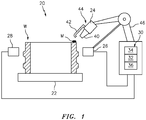
- FIG. 1 schematically illustrates an additive manufacturing system 20.
- the system 20 generally includes a build plate 22, a deposition system 24, a heater system 26, a sensor system 28 and a control system 30.
- the additive manufacturing system 20 builds components by consecutively melting layers of atomized alloy powder material to create the 3-D solid body workpiece W defined by a CAD file.
- Various metallic powders may be used, including iron, nickel, cobalt, titanium or aluminum-base alloys. Alloy 625, Alloy 718 and Alloy 230 may be used for components that operate in a high temperature environment such as is typical of aerospace and gas turbine engine components.
- additive manufacturing includes but is not limited to, Laser Freeform Manufacturing Technology (LFMT), Selective Laser Melting (SLM), Powder-Bed Electron Beam Melting (EBM), Electron Beam Free Form Fabrication (EBF3), Laser Engineered Net Shape (LENS), and others.
- LFMT Laser Freeform Manufacturing Technology
- SLM Selective Laser Melting
- EBM Powder-Bed Electron Beam Melting
- ETF3 Electron Beam Free Form Fabrication
- LENS Laser Engineered Net Shape
- the control system 30 includes a processor 32, a memory 34, and an interface 36.
- the processor 32 may be any type of microprocessor having desired performance characteristics.
- the memory 34 may include any type of computer readable medium which stores the data and control algorithms described herein such as the in-situ stress relief method 200 ( FIG. 2 ).
- Other operational software for the processor 32 may also be stored in the memory 34 to provide both manual and automatic programmable logic controller (PLC) inputs.
- PLC programmable logic controller
- the interface 36 facilitates communication with other subsystems such as the deposition system 24, the heater system 26, and the sensor system 28.
- the deposition system 24 includes a deposition nozzle 40 to generate a melt pool M and a gas cooling jet 42 to facilitate solidification of the melt pool M.
- the deposition nozzle 40 may direct a laser, electron beam, plasma arc, or other energy source.
- the gas cooling jet 42 may direct air or an inert gas.
- the deposition nozzle 40 and the gas cooling jet 42 are located on a deposition head 44 which is robotically manipulated by a motor drive 46 in response to the control system 30.
- the motor drive 46 may control the deposition head 44 within a coordinate system such that an example 6-axis machine has the ability to interpolate linearly for X, Y, Z, and rotationally A, B, and U.
- the functions of the motor drive 46 may be integrated into the control system 30 for positioning the deposition head 44.
- the control system 30 is operable to continually determine the position of the deposition head 44 with respect to the coordinate system.
- the sensor system 28 and the heater system 26 may be robotically manipulated in conjunction with the deposition system 24 by the control system 30 to maintain a desired position with respect to the deposition system 24.
- the sensor system 28 may include a multiple of temperature sensors 50 that alternate with a multiple of heaters 60 of the heater system 26 positioned around the workpiece W ( FIG. 3 ).
- the temperature sensors 50 are operable to identify a heat signature of the workpiece W.
- the temperature sensor 50 may be, for example, a thermal camera, an infrared camera, a semiconductor-based temperature sensor, or other measurement device.
- the heaters 60 may be, for example, an infrared heater, a laser, or other device to heat the workpiece and provide internal stress relief.
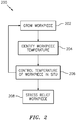
- the method 200 for in situ additive manufacturing stress relief is schematically disclosed in terms of a functional block diagram flowchart. It should be appreciated that alternative or additional steps may be provided without departing from the teaching herein.
- the workpiece W is grown (202; FIGS. 4-6 ) by consecutively melting layers of atomized alloy powder material applied to the build plate 22 by the deposition system 24.
- finer grain size provides greater ductility and fatigue life.
- the temperature sensors 50 identify the temperature of the workpiece W which trails the melt pool M.
- the heater system 26 then heats the workpiece W to elevate the workpiece W temperature to reduce the thermal gradient of the workpiece W and relax residual stress in situ during the additive manufacturing build process.
- the heater system 26 controls (206) the temperature of the workpiece W to provide localized stress relief by elevating the workpiece temperature in the areas below the melt pool M that are subject to high residual stresses.
- Such high residual stress areas may include features such as abrupt thickness changes, holes, or support structure adjacent to the build plate 22.
- Stress relief temperatures are lower than the point at which the phase change occurs. In steels and nickel alloys, stress relief can take place at temperatures between 500 - 1300 degrees F (260 - 704 degrees C). For aluminums, temperatures between 300 - 600 degrees F (149 - 316 degrees C) are more typical. Stress relief temperatures are highly alloy dependent and stress relief occurs more rapidly at the higher end of the temperature ranges.
- the workpiece W may be heated by the heater system 26 to an intermediate temperature, such that the internal stresses are mitigated sufficiently to counteract cracking and tearing.
- a temperature gradient in the workpiece W may be defined from the melt pool M deposition surface to the bottom of the workpiece W.
- a temperature gradient may conventionally be 2300 degrees F (1278 degrees C) over 1 inch (25.4 mm) of vertical distance on the workpiece W. That is, the melt pool M deposition surface is 2500 degrees F (1371 degrees C) and 200 degrees F (93 degrees C) at 1 inch (25.4 mm) below the melt pool M deposition surface.
- the temperature at the build plate 22 may be below 200 degrees F (93 degrees C).
- the temperature gradient is reduced to 1700 degrees F (944 degrees C) between the melt pool M deposition surface and the build plate 22. That is, the workpiece at the melt pool M deposition surface is 2500 degrees F (1371 degrees C) while the workpiece is 800 degrees F (427 degrees C) adjacent to the build plate 22 ( FIG. 7 ).
- the molten melt pool M temperature may be 1500 degrees F (816 degrees C) and the workpiece adjacent to the build plate may be 350 degrees F (177 degrees C).
- the temperature gradients may be specifically tailored for each workpiece alloy.
- the resultant reduced thermal gradient over the build height of the workpiece W moderates thermal shock and reduces the potential for cracking and separation from the build plate 22.
- the thermal gradient between the melt pool M and the build plate may be maintained at a uniform of 1200 - 600 degrees F (666 - 333 degrees C) for steel and nickel alloys, or at 300 degrees F (166 degrees C) for aluminum alloys.
- a complete stress relief operation (208) may then be performed on the finished workpiece W in a separate heat treat oven after the additive manufacturing build process is complete.
Landscapes
- Engineering & Computer Science (AREA)
- Physics & Mathematics (AREA)
- Optics & Photonics (AREA)
- Mechanical Engineering (AREA)
- Chemical & Material Sciences (AREA)
- Manufacturing & Machinery (AREA)
- Materials Engineering (AREA)
- Plasma & Fusion (AREA)
- Analytical Chemistry (AREA)
- Automation & Control Theory (AREA)
- Powder Metallurgy (AREA)
- Laser Beam Processing (AREA)
Abstract
Description
- The present disclosure relates generally to additive manufacturing systems and processes, and more particularly, to stress relief during the additive manufacturing build process.
- Additive manufacturing build processes such as Laser Freeform Manufacturing Technology (LFMT) are used to deposit "freeform" metal components with mechanical properties comparable to wrought materials. A build plate is often required as a base for the build. The build plate may be incorporated into the final part or may be removed when the freeform build is complete.
- There is a natural shrinkage that occurs when the additive manufacturing material solidifies from a liquid molten state. Then, further shrinkage occurs as the material cools from the solidification temperature to room temperature. This results in internal residual stresses and distortion. As free form metal additive manufacturing parts increase in size, for example, a gas turbine engine case that may be three or four feet in diameter, the shrinkage may be quite significant. The shrinkage may be significant enough to crack the part or break the part from the build plate.
- In an effort to avoid such damage, the build may be interrupted multiple times for external stress relief operations. Typically, in the example of a gas turbine engine case, external stress relief operations are performed every 3 to 6 inches (7.62 to 15.24 cm) of build. As engine cases are typically three to four feet (0.91 to 1.22 m) in height from the build plate, a significant number of interruptions are required. As the parts become larger, even with such interruptions for stress relief, the internal residual stress caused by the shrinkage becomes more severe such that the potential for cracks or the potential for the part to separate from the build plate significantly increases.
- An additive manufacturing system according to one disclosed non-limiting embodiment of the present invention includes a build plate; a deposition system operable to dispense material as a melt pool to additively manufacture a workpiece on the build plate; a sensor system operable to determine a temperature of the workpiece during additive manufacturing of workpiece; and a heater system operable to selectively heat the workpiece between the melt pool and the build plate during the additive manufacturing.
- A further aspect of the present disclosure includes a control in communication with the sensor system and the heater system, the control operable to control the heater system in response to a temperature measured on the workpiece by the sensor system to reduce a temperature gradient of the workpiece between the melt pool and the build plate.
- A further aspect of the present disclosure includes that the sensor system comprises a multiple of temperature sensors arranged around the build plate.
- A further aspect of the present disclosure includes that the heater system comprises a multiple of heaters arranged around the build plate.
- A further aspect of the present disclosure includes that the multiple of temperature sensors alternate with the multiple of heaters.
- A further aspect of the present disclosure includes that at least one of the multiple of temperature sensors is an infrared camera.
- A further aspect of the present disclosure includes that at least one of the multiple of heaters is a laser.
- A further aspect of the present disclosure includes that the deposition system comprises a deposition nozzle to generate the melt pool and a gas cooling jet to facilitate melt pool solidification.
- A method for in situ stress relief of a workpiece according to one disclosed non-limiting embodiment of the present invention includes additive manufacturing a workpiece on a build plate; sensing a temperature of the workpiece; and heating the workpiece at a location between a melt pool and the build plate in response to the sensing during the additive manufacturing.
- A further aspect of the present disclosure includes that the sensing is performed at a vertical height on the workpiece between the melt pool and the build plate.
- A further aspect of the present disclosure includes that the sensing comprises sensing the temperature of the workpiece at a multiple of positions around the workpiece.
- A further aspect of the present disclosure includes that the heating comprises heating the workpiece at a multiple of positions around the workpiece.
- A further aspect of the present disclosure includes that the heating comprises reducing a thermal gradient of the workpiece between the melt pool and the work piece.
- A further aspect of the present disclosure includes that the temperature is uniform between the melt pool and the build plate.
- A further aspect of the present disclosure includes that the thermal gradient is 2500 degrees F (1371°C) at the melt pool and 800 degrees F (427°C) at the build plate.
- The foregoing features and elements may be combined in various combinations without exclusivity, unless expressly indicated otherwise. These features and elements as well as the operation thereof will become more apparent in light of the following description and the accompanying drawings. It should be understood that the following description and drawings are intended to be exemplary in nature and non-limiting.
- Various features will become apparent to those skilled in the art from the following detailed description of the disclosed non-limiting embodiments. The drawings that accompany the detailed description can be briefly described as follows:
-
FIG. 1 is a general schematic view of an additive manufacturing system according to one disclosed non-liming embodiment; -
FIG. 2 is an additive manufacturing build process with in situ stress relief; -
FIG. 3 is a top view of the additive manufacturing system; -
FIGS. 4-6 are build process steps in the additive manufacturing build process; and -
FIG. 7 is a graphical representation of a thermal gradient in an additive manufactured workpiece manufactured with the system according to one disclosed non-limiting embodiment compared to a thermal gradient in a conventional additive manufactured process. -
FIG. 1 schematically illustrates anadditive manufacturing system 20. Thesystem 20 generally includes abuild plate 22, adeposition system 24, aheater system 26, asensor system 28 and acontrol system 30. Theadditive manufacturing system 20 builds components by consecutively melting layers of atomized alloy powder material to create the 3-D solid body workpiece W defined by a CAD file. Various metallic powders may be used, including iron, nickel, cobalt, titanium or aluminum-base alloys. Alloy 625, Alloy 718 and Alloy 230 may be used for components that operate in a high temperature environment such as is typical of aerospace and gas turbine engine components. As defined herein, "additive manufacturing" includes but is not limited to, Laser Freeform Manufacturing Technology (LFMT), Selective Laser Melting (SLM), Powder-Bed Electron Beam Melting (EBM), Electron Beam Free Form Fabrication (EBF3), Laser Engineered Net Shape (LENS), and others. - The
control system 30 includes aprocessor 32, amemory 34, and aninterface 36. Theprocessor 32 may be any type of microprocessor having desired performance characteristics. Thememory 34 may include any type of computer readable medium which stores the data and control algorithms described herein such as the in-situ stress relief method 200 (FIG. 2 ). Other operational software for theprocessor 32 may also be stored in thememory 34 to provide both manual and automatic programmable logic controller (PLC) inputs. Theinterface 36 facilitates communication with other subsystems such as thedeposition system 24, theheater system 26, and thesensor system 28. - The
deposition system 24 includes adeposition nozzle 40 to generate a melt pool M and agas cooling jet 42 to facilitate solidification of the melt pool M. Thedeposition nozzle 40 may direct a laser, electron beam, plasma arc, or other energy source. Thegas cooling jet 42 may direct air or an inert gas. Thedeposition nozzle 40 and thegas cooling jet 42 are located on adeposition head 44 which is robotically manipulated by amotor drive 46 in response to thecontrol system 30. Themotor drive 46 may control thedeposition head 44 within a coordinate system such that an example 6-axis machine has the ability to interpolate linearly for X, Y, Z, and rotationally A, B, and U. The functions of themotor drive 46 may be integrated into thecontrol system 30 for positioning thedeposition head 44. Thecontrol system 30 is operable to continually determine the position of thedeposition head 44 with respect to the coordinate system. - The
sensor system 28 and theheater system 26 may be robotically manipulated in conjunction with thedeposition system 24 by thecontrol system 30 to maintain a desired position with respect to thedeposition system 24. Thesensor system 28 may include a multiple oftemperature sensors 50 that alternate with a multiple ofheaters 60 of theheater system 26 positioned around the workpiece W (FIG. 3 ). Thetemperature sensors 50 are operable to identify a heat signature of the workpiece W. Thetemperature sensor 50 may be, for example, a thermal camera, an infrared camera, a semiconductor-based temperature sensor, or other measurement device. Theheaters 60 may be, for example, an infrared heater, a laser, or other device to heat the workpiece and provide internal stress relief. - With reference to
FIG. 2 , themethod 200 for in situ additive manufacturing stress relief is schematically disclosed in terms of a functional block diagram flowchart. It should be appreciated that alternative or additional steps may be provided without departing from the teaching herein. - Initially, in one embodiment, the workpiece W is grown (202;
FIGS. 4-6 ) by consecutively melting layers of atomized alloy powder material applied to thebuild plate 22 by thedeposition system 24. In some embodiments, it may be desirable to use an inert cooling gas jet to accelerate the solidification of the melt pool M to mitigate excessive grain grown. Generally, finer grain size provides greater ductility and fatigue life. - As the workpiece W is grown, the
temperature sensors 50 identify the temperature of the workpiece W which trails the melt pool M. Theheater system 26 then heats the workpiece W to elevate the workpiece W temperature to reduce the thermal gradient of the workpiece W and relax residual stress in situ during the additive manufacturing build process. - During the additive manufacturing build process, the
heater system 26 controls (206) the temperature of the workpiece W to provide localized stress relief by elevating the workpiece temperature in the areas below the melt pool M that are subject to high residual stresses. Such high residual stress areas may include features such as abrupt thickness changes, holes, or support structure adjacent to thebuild plate 22. Stress relief temperatures are lower than the point at which the phase change occurs. In steels and nickel alloys, stress relief can take place at temperatures between 500 - 1300 degrees F (260 - 704 degrees C). For aluminums, temperatures between 300 - 600 degrees F (149 - 316 degrees C) are more typical. Stress relief temperatures are highly alloy dependent and stress relief occurs more rapidly at the higher end of the temperature ranges. - During the additive manufacturing build process, the workpiece W may be heated by the
heater system 26 to an intermediate temperature, such that the internal stresses are mitigated sufficiently to counteract cracking and tearing. For example, a temperature gradient in the workpiece W may be defined from the melt pool M deposition surface to the bottom of the workpiece W. A temperature gradient may conventionally be 2300 degrees F (1278 degrees C) over 1 inch (25.4 mm) of vertical distance on the workpiece W. That is, the melt pool M deposition surface is 2500 degrees F (1371 degrees C) and 200 degrees F (93 degrees C) at 1 inch (25.4 mm) below the melt pool M deposition surface. The temperature at thebuild plate 22 may be below 200 degrees F (93 degrees C). - With the
system 20, the temperature gradient is reduced to 1700 degrees F (944 degrees C) between the melt pool M deposition surface and thebuild plate 22. That is, the workpiece at the melt pool M deposition surface is 2500 degrees F (1371 degrees C) while the workpiece is 800 degrees F (427 degrees C) adjacent to the build plate 22 (FIG. 7 ). For a lower temperature material, such as aluminum, the molten melt pool M temperature may be 1500 degrees F (816 degrees C) and the workpiece adjacent to the build plate may be 350 degrees F (177 degrees C). The temperature gradients may be specifically tailored for each workpiece alloy. The resultant reduced thermal gradient over the build height of the workpiece W moderates thermal shock and reduces the potential for cracking and separation from thebuild plate 22. In other examples, the thermal gradient between the melt pool M and the build plate may be maintained at a uniform of 1200 - 600 degrees F (666 - 333 degrees C) for steel and nickel alloys, or at 300 degrees F (166 degrees C) for aluminum alloys. - Finally, a complete stress relief operation (208) may then be performed on the finished workpiece W in a separate heat treat oven after the additive manufacturing build process is complete.
- The use of the terms "a," and "an," and "the," and similar references in the context of description (especially in the context of the following claims) are to be construed to cover both the singular and the plural, unless otherwise indicated herein or specifically contradicted by context. The modifier "" used in connection with a quantity is inclusive of the stated value and has the meaning dictated by the context (e.g., it includes the degrees of error associated with measurement of the particular quantity). All ranges disclosed herein are inclusive of the endpoints, and the endpoints are independently combinable with each other. It should be appreciated that relative positional terms such as "forward," "aft," "upper," "lower," "above," "below," and the like are with reference to the normal operational attitude of the equipment and should not be considered otherwise limiting.
- Although the different non-limiting embodiments have specific illustrated components, the embodiments of this invention are not limited to those particular combinations. It is possible to use some of the components or features from any of the non-limiting embodiments in combination with features or components from any of the other non-limiting embodiments.
- It should be appreciated that like reference numerals identify corresponding or similar elements throughout the several drawings. It should also be appreciated that although a particular component arrangement is disclosed in the illustrated embodiment, other arrangements will benefit herefrom.
- Although particular step sequences are shown, described, and claimed, it should be understood that steps may be performed in any order, separated or combined unless otherwise indicated and will still benefit from the present disclosure.
- The foregoing description is exemplary rather than defined by the limitations within. Various non-limiting embodiments are disclosed herein, however, one of ordinary skill in the art would recognize that various modifications and variations in light of the above teachings will fall within the scope of the appended claims. It is therefore to be understood that within the scope of the appended claims, the disclosure may be practiced other than as specifically described. For that reason, the appended claims should be studied to determine true scope and content.
Claims (15)
- An additive manufacturing system (20), comprising:a build plate (22);a deposition system (24) operable to dispense material as a melt pool (M) to additively manufacture a workpiece (W) on the build plate (22);a sensor system (28) operable to determine a temperature of the workpiece (W) during additive manufacturing of workpiece (W); anda heater system (26) operable to selectively heat the workpiece (W) between the melt pool (M) and the build plate (22) during the additive manufacturing.
- The system (20) as recited in claim 1, wherein the sensor system (28) comprises a multiple of temperature sensors (50) arranged around the build plate (22).
- The system (20) as recited in claim 2, wherein at least one of the multiple of temperature sensors (50) is an infrared camera.
- The system (20) as recited in any preceding claim, wherein the heater system (26) comprises a multiple of heaters (60) arranged around the build plate (22).
- The system (20) as recited in claim 4, wherein at least one of the multiple of heaters (60) is a laser.
- The system (20) as recited in claim 4 or 5 as dependent on claim 2, wherein the multiple of temperature sensors (50) alternate with the multiple of heaters (60).
- The system (20) as recited in any preceding claim, further comprising a control (30) in communication with the sensor system (28) and the heater system (26), the control (30) operable to control the heater system (26) in response to a temperature measured on the workpiece (W) by the sensor system (28) to reduce a temperature gradient of the workpiece (W) between the melt pool (M) and the build plate (22).
- The system (20) as recited in any preceding claim, wherein the deposition system (24) comprises a deposition nozzle (40) to generate the melt pool (M) and a gas cooling jet (42) to facilitate melt pool solidification.
- A method for in situ stress relief of a workpiece (W), comprising:additive manufacturing a workpiece (W) on a build plate (22);sensing a temperature of the workpiece (W); andheating the workpiece (W) at a location between a melt pool (M) and the build plate (22) in response to the sensing during the additive manufacturing.
- The method as recited in claim 9, wherein the sensing is performed at a vertical height on the workpiece (W) between the melt pool (M) and the build plate (22).
- The method as recited in claim 9 or 10, wherein the sensing comprises sensing the temperature of the workpiece (W) at a multiple of positions around the workpiece (W).
- The method as recited in any of claims 9 to 11, wherein the heating comprises heating the workpiece (W) at a multiple of positions around the workpiece (W).
- The method as recited in any of claims 9 to 12, wherein the heating comprises reducing a thermal gradient of the workpiece (W) between the melt pool (M) and the build plate (22).
- The method as recited in claim 13, wherein the thermal gradient is uniform between the melt pool (M) and the build plate (22).
- The method as recited in claim 13 or 14, wherein the temperature of the workpiece (W) is about 2500 degrees F (1371°C) adjacent the melt pool (M) location and about 800 degrees F (427°C) at the workpiece (W) adjacent the build plate (22).
Applications Claiming Priority (1)
| Application Number | Priority Date | Filing Date | Title |
|---|---|---|---|
| US15/714,033 US10933493B2 (en) | 2017-09-25 | 2017-09-25 | Additive manufacturing in situ stress relief |
Publications (2)
| Publication Number | Publication Date |
|---|---|
| EP3459673A1 true EP3459673A1 (en) | 2019-03-27 |
| EP3459673B1 EP3459673B1 (en) | 2023-10-25 |
Family
ID=63685611
Family Applications (1)
| Application Number | Title | Priority Date | Filing Date |
|---|---|---|---|
| EP18196692.0A Active EP3459673B1 (en) | 2017-09-25 | 2018-09-25 | Additive manufacturing in situ stress relief |
Country Status (2)
| Country | Link |
|---|---|
| US (1) | US10933493B2 (en) |
| EP (1) | EP3459673B1 (en) |
Cited By (2)
| Publication number | Priority date | Publication date | Assignee | Title |
|---|---|---|---|---|
| CN110241416A (en) * | 2019-07-10 | 2019-09-17 | 宁波中物东方光电技术有限公司 | Laser melting coating quenches comprehensive process device and processing method |
| EP3878581A1 (en) * | 2020-03-12 | 2021-09-15 | Xerox Corporation | Method and system for operating a modular heater to improve layer bonding in a metal drop ejecting three-dimensional (3d) object printer |
Families Citing this family (6)
| Publication number | Priority date | Publication date | Assignee | Title |
|---|---|---|---|---|
| JP6843968B2 (en) | 2016-08-22 | 2021-03-17 | ストラタシス,インコーポレイテッド | How to print 3D parts using a multi-axis robot build system and how to print parts outside the oven 3D |
| EP3599080A1 (en) * | 2018-07-27 | 2020-01-29 | Concept Laser GmbH | Apparatus for additively manufacturing three-dimensional objects |
| US12128631B2 (en) | 2018-08-17 | 2024-10-29 | Stratasys, Inc. | Method of analyzing and utilizing surface topology for targeted local thermal management in additive manufacturing systems |
| CN113909633B (en) * | 2021-10-01 | 2023-07-18 | 江苏烁石焊接科技有限公司 | Synchronous heating stress deformation control system and method for robot arc material-adding shaft parts |
| CN115255399A (en) * | 2022-08-05 | 2022-11-01 | 西安交通大学 | 3D printing device and method for eliminating printing defects by utilizing micro-area synchronous heat treatment |
| DE102023004402B3 (en) | 2023-11-03 | 2025-03-13 | Mercedes-Benz Group AG | Method for additive manufacturing and process unit for controlling an additive manufacturing system |
Citations (2)
| Publication number | Priority date | Publication date | Assignee | Title |
|---|---|---|---|---|
| US20070205184A1 (en) * | 2006-01-30 | 2007-09-06 | Jyoti Mazumder | High-speed, ultra precision manufacturing station that combines direct metal deposition and edm |
| EP3132885A1 (en) * | 2015-08-20 | 2017-02-22 | General Electric Company | Apparatus and method for direct writing of single crystal super alloys and metals |
Family Cites Families (6)
| Publication number | Priority date | Publication date | Assignee | Title |
|---|---|---|---|---|
| US20090283501A1 (en) * | 2008-05-15 | 2009-11-19 | General Electric Company | Preheating using a laser beam |
| EP2789413B1 (en) | 2013-04-08 | 2019-01-16 | MTU Aero Engines AG | Temperature control for a device for the generative production of components and a corresponding manufacturing method |
| WO2014202413A2 (en) | 2013-06-20 | 2014-12-24 | MTU Aero Engines AG | Device and method for additively producing at least one component region of a component |
| US10935241B2 (en) * | 2014-05-09 | 2021-03-02 | Raytheon Technologies Corporation | Additively manufactured hotspot portion of a turbine engine component having heat resistant properties and method of manufacture |
| US10618111B2 (en) | 2016-01-28 | 2020-04-14 | Lawrence Livermore National Security, Llc | Heat treatment to anneal residual stresses during additive manufacturing |
| US10710307B2 (en) * | 2017-08-11 | 2020-07-14 | Applied Materials, Inc. | Temperature control for additive manufacturing |
-
2017
- 2017-09-25 US US15/714,033 patent/US10933493B2/en active Active
-
2018
- 2018-09-25 EP EP18196692.0A patent/EP3459673B1/en active Active
Patent Citations (2)
| Publication number | Priority date | Publication date | Assignee | Title |
|---|---|---|---|---|
| US20070205184A1 (en) * | 2006-01-30 | 2007-09-06 | Jyoti Mazumder | High-speed, ultra precision manufacturing station that combines direct metal deposition and edm |
| EP3132885A1 (en) * | 2015-08-20 | 2017-02-22 | General Electric Company | Apparatus and method for direct writing of single crystal super alloys and metals |
Cited By (4)
| Publication number | Priority date | Publication date | Assignee | Title |
|---|---|---|---|---|
| CN110241416A (en) * | 2019-07-10 | 2019-09-17 | 宁波中物东方光电技术有限公司 | Laser melting coating quenches comprehensive process device and processing method |
| CN110241416B (en) * | 2019-07-10 | 2023-07-07 | 宁波中物东方光电技术有限公司 | Comprehensive processing device and processing method for laser cladding quenching |
| EP3878581A1 (en) * | 2020-03-12 | 2021-09-15 | Xerox Corporation | Method and system for operating a modular heater to improve layer bonding in a metal drop ejecting three-dimensional (3d) object printer |
| US11485089B2 (en) | 2020-03-12 | 2022-11-01 | Xerox Corporation | Method and system for operating a modular heater to improve layer bonding in a metal drop ejecting three-dimensional (3D) object printer |
Also Published As
| Publication number | Publication date |
|---|---|
| US10933493B2 (en) | 2021-03-02 |
| US20190091803A1 (en) | 2019-03-28 |
| EP3459673B1 (en) | 2023-10-25 |
Similar Documents
| Publication | Publication Date | Title |
|---|---|---|
| EP3459673B1 (en) | Additive manufacturing in situ stress relief | |
| Singh et al. | Wire arc additive manufacturing (WAAM): A new process to shape engineering materials | |
| CA2794015C (en) | A process for the production of articles made of a gamma-prime precipitation-strengthened nickel-base superalloy by selective laser melting (slm) | |
| EP3693105B1 (en) | Method for manufacturing an article | |
| EP2969383B2 (en) | Repair of gas turbine engine components | |
| EP3064295B1 (en) | Process for producing a compressor blade | |
| EP3034639B1 (en) | Nickel-based superalloys and additive manufacturing processes using nickel-based superalloys | |
| EP3135408B1 (en) | Powder-bed additive manufacturing device and method | |
| EP3587005A1 (en) | Control method for layerwise additive manufacturing, computer program product and control apparatus | |
| EP4104951A1 (en) | Turbomachine manufacture and repair method using additive manufactured braze preforms | |
| KR20190019080A (en) | How to create components and components | |
| CA3068408C (en) | An additive manufacturing technique for precipitation-hardened superalloy powdered material | |
| JP2018532050A (en) | Apparatus and method for additive manufacturing | |
| CN111545747B (en) | Method for additive manufacturing of a component with reduced build failure due to temperature variation | |
| JP2024527797A (en) | Systems and methods for additive metal casting | |
| Kumar et al. | Additive manufacturing with welding | |
| Khan et al. | Fabrication of AISI 434L Stainless Steel Thin Wall Structures by TIG-Aided Powder Bed Fusion Arc Additive Manufacturing: Evaluation of Metallurgical Characteristics and Mechanical Properties: MDA Khan et al. | |
| US20240139814A1 (en) | Removing the Support Structure by Means of a Laser Beam Integrated on a Robot Arm | |
| US20220362857A1 (en) | Method and apparatus for fabrication of articles by molten and semi-molten deposition | |
| US12472553B2 (en) | System and method for forming single crystal components using additive manufacturing tooling | |
| Milewski | Current system configurations | |
| EP4365766B1 (en) | Additive manufactured component including witness lines | |
| Akbari | Development of a robotized laser directed energy deposition system and process challenges | |
| US20160298780A1 (en) | Furnace braze deposition of hardface coating on wear surface | |
| US20220258266A1 (en) | Method and apparatus for fabrication of articles by molten and semi-molten deposition |
Legal Events
| Date | Code | Title | Description |
|---|---|---|---|
| PUAI | Public reference made under article 153(3) epc to a published international application that has entered the european phase |
Free format text: ORIGINAL CODE: 0009012 |
|
| STAA | Information on the status of an ep patent application or granted ep patent |
Free format text: STATUS: THE APPLICATION HAS BEEN PUBLISHED |
|
| AK | Designated contracting states |
Kind code of ref document: A1 Designated state(s): AL AT BE BG CH CY CZ DE DK EE ES FI FR GB GR HR HU IE IS IT LI LT LU LV MC MK MT NL NO PL PT RO RS SE SI SK SM TR |
|
| AX | Request for extension of the european patent |
Extension state: BA ME |
|
| STAA | Information on the status of an ep patent application or granted ep patent |
Free format text: STATUS: REQUEST FOR EXAMINATION WAS MADE |
|
| 17P | Request for examination filed |
Effective date: 20190927 |
|
| RBV | Designated contracting states (corrected) |
Designated state(s): AL AT BE BG CH CY CZ DE DK EE ES FI FR GB GR HR HU IE IS IT LI LT LU LV MC MK MT NL NO PL PT RO RS SE SI SK SM TR |
|
| STAA | Information on the status of an ep patent application or granted ep patent |
Free format text: STATUS: EXAMINATION IS IN PROGRESS |
|
| 17Q | First examination report despatched |
Effective date: 20201112 |
|
| RAP1 | Party data changed (applicant data changed or rights of an application transferred) |
Owner name: RAYTHEON TECHNOLOGIES CORPORATION |
|
| GRAP | Despatch of communication of intention to grant a patent |
Free format text: ORIGINAL CODE: EPIDOSNIGR1 |
|
| STAA | Information on the status of an ep patent application or granted ep patent |
Free format text: STATUS: GRANT OF PATENT IS INTENDED |
|
| INTG | Intention to grant announced |
Effective date: 20220929 |
|
| RIN1 | Information on inventor provided before grant (corrected) |
Inventor name: TWELVES, WENDELL V. |
|
| GRAJ | Information related to disapproval of communication of intention to grant by the applicant or resumption of examination proceedings by the epo deleted |
Free format text: ORIGINAL CODE: EPIDOSDIGR1 |
|
| STAA | Information on the status of an ep patent application or granted ep patent |
Free format text: STATUS: EXAMINATION IS IN PROGRESS |
|
| INTC | Intention to grant announced (deleted) | ||
| GRAP | Despatch of communication of intention to grant a patent |
Free format text: ORIGINAL CODE: EPIDOSNIGR1 |
|
| STAA | Information on the status of an ep patent application or granted ep patent |
Free format text: STATUS: GRANT OF PATENT IS INTENDED |
|
| INTG | Intention to grant announced |
Effective date: 20230418 |
|
| GRAS | Grant fee paid |
Free format text: ORIGINAL CODE: EPIDOSNIGR3 |
|
| GRAA | (expected) grant |
Free format text: ORIGINAL CODE: 0009210 |
|
| STAA | Information on the status of an ep patent application or granted ep patent |
Free format text: STATUS: THE PATENT HAS BEEN GRANTED |
|
| AK | Designated contracting states |
Kind code of ref document: B1 Designated state(s): AL AT BE BG CH CY CZ DE DK EE ES FI FR GB GR HR HU IE IS IT LI LT LU LV MC MK MT NL NO PL PT RO RS SE SI SK SM TR |
|
| REG | Reference to a national code |
Ref country code: GB Ref legal event code: FG4D |
|
| REG | Reference to a national code |
Ref country code: CH Ref legal event code: EP |
|
| RAP4 | Party data changed (patent owner data changed or rights of a patent transferred) |
Owner name: RTX CORPORATION |
|
| REG | Reference to a national code |
Ref country code: DE Ref legal event code: R096 Ref document number: 602018059856 Country of ref document: DE |
|
| REG | Reference to a national code |
Ref country code: IE Ref legal event code: FG4D |
|
| REG | Reference to a national code |
Ref country code: LT Ref legal event code: MG9D |
|
| REG | Reference to a national code |
Ref country code: NL Ref legal event code: MP Effective date: 20231025 |
|
| REG | Reference to a national code |
Ref country code: AT Ref legal event code: MK05 Ref document number: 1624188 Country of ref document: AT Kind code of ref document: T Effective date: 20231025 |
|
| PG25 | Lapsed in a contracting state [announced via postgrant information from national office to epo] |
Ref country code: NL Free format text: LAPSE BECAUSE OF FAILURE TO SUBMIT A TRANSLATION OF THE DESCRIPTION OR TO PAY THE FEE WITHIN THE PRESCRIBED TIME-LIMIT Effective date: 20231025 |
|
| PG25 | Lapsed in a contracting state [announced via postgrant information from national office to epo] |
Ref country code: GR Free format text: LAPSE BECAUSE OF FAILURE TO SUBMIT A TRANSLATION OF THE DESCRIPTION OR TO PAY THE FEE WITHIN THE PRESCRIBED TIME-LIMIT Effective date: 20240126 |
|
| PG25 | Lapsed in a contracting state [announced via postgrant information from national office to epo] |
Ref country code: IS Free format text: LAPSE BECAUSE OF FAILURE TO SUBMIT A TRANSLATION OF THE DESCRIPTION OR TO PAY THE FEE WITHIN THE PRESCRIBED TIME-LIMIT Effective date: 20240225 |
|
| PG25 | Lapsed in a contracting state [announced via postgrant information from national office to epo] |
Ref country code: LT Free format text: LAPSE BECAUSE OF FAILURE TO SUBMIT A TRANSLATION OF THE DESCRIPTION OR TO PAY THE FEE WITHIN THE PRESCRIBED TIME-LIMIT Effective date: 20231025 |
|
| PG25 | Lapsed in a contracting state [announced via postgrant information from national office to epo] |
Ref country code: AT Free format text: LAPSE BECAUSE OF FAILURE TO SUBMIT A TRANSLATION OF THE DESCRIPTION OR TO PAY THE FEE WITHIN THE PRESCRIBED TIME-LIMIT Effective date: 20231025 |
|
| PG25 | Lapsed in a contracting state [announced via postgrant information from national office to epo] |
Ref country code: ES Free format text: LAPSE BECAUSE OF FAILURE TO SUBMIT A TRANSLATION OF THE DESCRIPTION OR TO PAY THE FEE WITHIN THE PRESCRIBED TIME-LIMIT Effective date: 20231025 |
|
| PG25 | Lapsed in a contracting state [announced via postgrant information from national office to epo] |
Ref country code: LT Free format text: LAPSE BECAUSE OF FAILURE TO SUBMIT A TRANSLATION OF THE DESCRIPTION OR TO PAY THE FEE WITHIN THE PRESCRIBED TIME-LIMIT Effective date: 20231025 Ref country code: IS Free format text: LAPSE BECAUSE OF FAILURE TO SUBMIT A TRANSLATION OF THE DESCRIPTION OR TO PAY THE FEE WITHIN THE PRESCRIBED TIME-LIMIT Effective date: 20240225 Ref country code: GR Free format text: LAPSE BECAUSE OF FAILURE TO SUBMIT A TRANSLATION OF THE DESCRIPTION OR TO PAY THE FEE WITHIN THE PRESCRIBED TIME-LIMIT Effective date: 20240126 Ref country code: ES Free format text: LAPSE BECAUSE OF FAILURE TO SUBMIT A TRANSLATION OF THE DESCRIPTION OR TO PAY THE FEE WITHIN THE PRESCRIBED TIME-LIMIT Effective date: 20231025 Ref country code: BG Free format text: LAPSE BECAUSE OF FAILURE TO SUBMIT A TRANSLATION OF THE DESCRIPTION OR TO PAY THE FEE WITHIN THE PRESCRIBED TIME-LIMIT Effective date: 20240125 Ref country code: AT Free format text: LAPSE BECAUSE OF FAILURE TO SUBMIT A TRANSLATION OF THE DESCRIPTION OR TO PAY THE FEE WITHIN THE PRESCRIBED TIME-LIMIT Effective date: 20231025 Ref country code: PT Free format text: LAPSE BECAUSE OF FAILURE TO SUBMIT A TRANSLATION OF THE DESCRIPTION OR TO PAY THE FEE WITHIN THE PRESCRIBED TIME-LIMIT Effective date: 20240226 |
|
| PG25 | Lapsed in a contracting state [announced via postgrant information from national office to epo] |
Ref country code: SE Free format text: LAPSE BECAUSE OF FAILURE TO SUBMIT A TRANSLATION OF THE DESCRIPTION OR TO PAY THE FEE WITHIN THE PRESCRIBED TIME-LIMIT Effective date: 20231025 Ref country code: RS Free format text: LAPSE BECAUSE OF FAILURE TO SUBMIT A TRANSLATION OF THE DESCRIPTION OR TO PAY THE FEE WITHIN THE PRESCRIBED TIME-LIMIT Effective date: 20231025 Ref country code: PL Free format text: LAPSE BECAUSE OF FAILURE TO SUBMIT A TRANSLATION OF THE DESCRIPTION OR TO PAY THE FEE WITHIN THE PRESCRIBED TIME-LIMIT Effective date: 20231025 Ref country code: NO Free format text: LAPSE BECAUSE OF FAILURE TO SUBMIT A TRANSLATION OF THE DESCRIPTION OR TO PAY THE FEE WITHIN THE PRESCRIBED TIME-LIMIT Effective date: 20240125 Ref country code: LV Free format text: LAPSE BECAUSE OF FAILURE TO SUBMIT A TRANSLATION OF THE DESCRIPTION OR TO PAY THE FEE WITHIN THE PRESCRIBED TIME-LIMIT Effective date: 20231025 Ref country code: HR Free format text: LAPSE BECAUSE OF FAILURE TO SUBMIT A TRANSLATION OF THE DESCRIPTION OR TO PAY THE FEE WITHIN THE PRESCRIBED TIME-LIMIT Effective date: 20231025 |
|
| PG25 | Lapsed in a contracting state [announced via postgrant information from national office to epo] |
Ref country code: DK Free format text: LAPSE BECAUSE OF FAILURE TO SUBMIT A TRANSLATION OF THE DESCRIPTION OR TO PAY THE FEE WITHIN THE PRESCRIBED TIME-LIMIT Effective date: 20231025 |
|
| PG25 | Lapsed in a contracting state [announced via postgrant information from national office to epo] |
Ref country code: CZ Free format text: LAPSE BECAUSE OF FAILURE TO SUBMIT A TRANSLATION OF THE DESCRIPTION OR TO PAY THE FEE WITHIN THE PRESCRIBED TIME-LIMIT Effective date: 20231025 |
|
| REG | Reference to a national code |
Ref country code: DE Ref legal event code: R097 Ref document number: 602018059856 Country of ref document: DE |
|
| PG25 | Lapsed in a contracting state [announced via postgrant information from national office to epo] |
Ref country code: SK Free format text: LAPSE BECAUSE OF FAILURE TO SUBMIT A TRANSLATION OF THE DESCRIPTION OR TO PAY THE FEE WITHIN THE PRESCRIBED TIME-LIMIT Effective date: 20231025 |
|
| PG25 | Lapsed in a contracting state [announced via postgrant information from national office to epo] |
Ref country code: SM Free format text: LAPSE BECAUSE OF FAILURE TO SUBMIT A TRANSLATION OF THE DESCRIPTION OR TO PAY THE FEE WITHIN THE PRESCRIBED TIME-LIMIT Effective date: 20231025 Ref country code: SK Free format text: LAPSE BECAUSE OF FAILURE TO SUBMIT A TRANSLATION OF THE DESCRIPTION OR TO PAY THE FEE WITHIN THE PRESCRIBED TIME-LIMIT Effective date: 20231025 Ref country code: RO Free format text: LAPSE BECAUSE OF FAILURE TO SUBMIT A TRANSLATION OF THE DESCRIPTION OR TO PAY THE FEE WITHIN THE PRESCRIBED TIME-LIMIT Effective date: 20231025 Ref country code: EE Free format text: LAPSE BECAUSE OF FAILURE TO SUBMIT A TRANSLATION OF THE DESCRIPTION OR TO PAY THE FEE WITHIN THE PRESCRIBED TIME-LIMIT Effective date: 20231025 Ref country code: DK Free format text: LAPSE BECAUSE OF FAILURE TO SUBMIT A TRANSLATION OF THE DESCRIPTION OR TO PAY THE FEE WITHIN THE PRESCRIBED TIME-LIMIT Effective date: 20231025 Ref country code: CZ Free format text: LAPSE BECAUSE OF FAILURE TO SUBMIT A TRANSLATION OF THE DESCRIPTION OR TO PAY THE FEE WITHIN THE PRESCRIBED TIME-LIMIT Effective date: 20231025 |
|
| PLBE | No opposition filed within time limit |
Free format text: ORIGINAL CODE: 0009261 |
|
| STAA | Information on the status of an ep patent application or granted ep patent |
Free format text: STATUS: NO OPPOSITION FILED WITHIN TIME LIMIT |
|
| 26N | No opposition filed |
Effective date: 20240726 |
|
| PG25 | Lapsed in a contracting state [announced via postgrant information from national office to epo] |
Ref country code: SI Free format text: LAPSE BECAUSE OF FAILURE TO SUBMIT A TRANSLATION OF THE DESCRIPTION OR TO PAY THE FEE WITHIN THE PRESCRIBED TIME-LIMIT Effective date: 20231025 |
|
| PG25 | Lapsed in a contracting state [announced via postgrant information from national office to epo] |
Ref country code: SI Free format text: LAPSE BECAUSE OF FAILURE TO SUBMIT A TRANSLATION OF THE DESCRIPTION OR TO PAY THE FEE WITHIN THE PRESCRIBED TIME-LIMIT Effective date: 20231025 |
|
| PG25 | Lapsed in a contracting state [announced via postgrant information from national office to epo] |
Ref country code: MC Free format text: LAPSE BECAUSE OF FAILURE TO SUBMIT A TRANSLATION OF THE DESCRIPTION OR TO PAY THE FEE WITHIN THE PRESCRIBED TIME-LIMIT Effective date: 20231025 |
|
| REG | Reference to a national code |
Ref country code: CH Ref legal event code: PL |
|
| PG25 | Lapsed in a contracting state [announced via postgrant information from national office to epo] |
Ref country code: LU Free format text: LAPSE BECAUSE OF NON-PAYMENT OF DUE FEES Effective date: 20240925 |
|
| REG | Reference to a national code |
Ref country code: BE Ref legal event code: MM Effective date: 20240930 |
|
| PG25 | Lapsed in a contracting state [announced via postgrant information from national office to epo] |
Ref country code: IT Free format text: LAPSE BECAUSE OF NON-PAYMENT OF DUE FEES Effective date: 20240925 Ref country code: BE Free format text: LAPSE BECAUSE OF NON-PAYMENT OF DUE FEES Effective date: 20240930 |
|
| PG25 | Lapsed in a contracting state [announced via postgrant information from national office to epo] |
Ref country code: CH Free format text: LAPSE BECAUSE OF NON-PAYMENT OF DUE FEES Effective date: 20240930 |
|
| PG25 | Lapsed in a contracting state [announced via postgrant information from national office to epo] |
Ref country code: IE Free format text: LAPSE BECAUSE OF NON-PAYMENT OF DUE FEES Effective date: 20240925 |
|
| REG | Reference to a national code |
Ref country code: DE Ref legal event code: R081 Ref document number: 602018059856 Country of ref document: DE Owner name: RTX CORPORATION (N.D.GES.D. STAATES DELAWARE),, US Free format text: FORMER OWNER: RAYTHEON TECHNOLOGIES CORPORATION, FARMINGTON, CT, US |
|
| PG25 | Lapsed in a contracting state [announced via postgrant information from national office to epo] |
Ref country code: FI Free format text: LAPSE BECAUSE OF FAILURE TO SUBMIT A TRANSLATION OF THE DESCRIPTION OR TO PAY THE FEE WITHIN THE PRESCRIBED TIME-LIMIT Effective date: 20231025 |
|
| PGFP | Annual fee paid to national office [announced via postgrant information from national office to epo] |
Ref country code: DE Payment date: 20250820 Year of fee payment: 8 |
|
| PGFP | Annual fee paid to national office [announced via postgrant information from national office to epo] |
Ref country code: GB Payment date: 20250822 Year of fee payment: 8 |
|
| PGFP | Annual fee paid to national office [announced via postgrant information from national office to epo] |
Ref country code: FR Payment date: 20250821 Year of fee payment: 8 |
|
| P01 | Opt-out of the competence of the unified patent court (upc) registered |
Free format text: CASE NUMBER: UPC_APP_0017876_3459673/2025 Effective date: 20251217 |
|
| PG25 | Lapsed in a contracting state [announced via postgrant information from national office to epo] |
Ref country code: CY Free format text: LAPSE BECAUSE OF FAILURE TO SUBMIT A TRANSLATION OF THE DESCRIPTION OR TO PAY THE FEE WITHIN THE PRESCRIBED TIME-LIMIT; INVALID AB INITIO Effective date: 20180925 |
|
| PG25 | Lapsed in a contracting state [announced via postgrant information from national office to epo] |
Ref country code: HU Free format text: LAPSE BECAUSE OF FAILURE TO SUBMIT A TRANSLATION OF THE DESCRIPTION OR TO PAY THE FEE WITHIN THE PRESCRIBED TIME-LIMIT; INVALID AB INITIO Effective date: 20180925 |