EP3459507A2 - Formverfahren einer sohle in einem negativabdruck, und vorrichtung und system zum formen einer sohle für dessen umsetzung - Google Patents
Formverfahren einer sohle in einem negativabdruck, und vorrichtung und system zum formen einer sohle für dessen umsetzung Download PDFInfo
- Publication number
- EP3459507A2 EP3459507A2 EP18191605.7A EP18191605A EP3459507A2 EP 3459507 A2 EP3459507 A2 EP 3459507A2 EP 18191605 A EP18191605 A EP 18191605A EP 3459507 A2 EP3459507 A2 EP 3459507A2
- Authority
- EP
- European Patent Office
- Prior art keywords
- vacuum
- sole
- forming
- connecting means
- Prior art date
- Legal status (The legal status is an assumption and is not a legal conclusion. Google has not performed a legal analysis and makes no representation as to the accuracy of the status listed.)
- Withdrawn
Links
- 238000000034 method Methods 0.000 title claims abstract description 20
- 239000000463 material Substances 0.000 claims abstract description 21
- 238000007666 vacuum forming Methods 0.000 claims abstract description 20
- 238000004891 communication Methods 0.000 claims description 16
- 239000012528 membrane Substances 0.000 claims description 15
- 229920001296 polysiloxane Polymers 0.000 claims description 7
- 238000007789 sealing Methods 0.000 claims description 7
- 230000007704 transition Effects 0.000 claims description 7
- 230000002093 peripheral effect Effects 0.000 claims description 6
- 238000011144 upstream manufacturing Methods 0.000 claims description 5
- 230000008878 coupling Effects 0.000 claims description 4
- 238000010168 coupling process Methods 0.000 claims description 4
- 238000005859 coupling reaction Methods 0.000 claims description 4
- 125000006850 spacer group Chemical class 0.000 claims description 4
- 239000000700 radioactive tracer Substances 0.000 claims description 3
- 238000003856 thermoforming Methods 0.000 description 6
- 238000003825 pressing Methods 0.000 description 4
- 238000001816 cooling Methods 0.000 description 3
- 238000004519 manufacturing process Methods 0.000 description 3
- 230000000284 resting effect Effects 0.000 description 3
- 230000003584 silencer Effects 0.000 description 3
- 102100032449 EGF-like repeat and discoidin I-like domain-containing protein 3 Human genes 0.000 description 2
- 101001016381 Homo sapiens EGF-like repeat and discoidin I-like domain-containing protein 3 Proteins 0.000 description 2
- 241001272720 Medialuna californiensis Species 0.000 description 2
- 238000004026 adhesive bonding Methods 0.000 description 2
- 239000013256 coordination polymer Substances 0.000 description 2
- 238000010586 diagram Methods 0.000 description 2
- 230000000399 orthopedic effect Effects 0.000 description 2
- 239000002516 radical scavenger Substances 0.000 description 2
- 239000007787 solid Substances 0.000 description 2
- 101100278884 Arabidopsis thaliana E2FD gene Proteins 0.000 description 1
- 230000000712 assembly Effects 0.000 description 1
- 238000000429 assembly Methods 0.000 description 1
- 230000008901 benefit Effects 0.000 description 1
- 238000006073 displacement reaction Methods 0.000 description 1
- 239000012530 fluid Substances 0.000 description 1
- 239000008187 granular material Substances 0.000 description 1
- 238000012423 maintenance Methods 0.000 description 1
- 239000011325 microbead Substances 0.000 description 1
- 230000008569 process Effects 0.000 description 1
- 238000007493 shaping process Methods 0.000 description 1
- 230000003068 static effect Effects 0.000 description 1
- 230000009466 transformation Effects 0.000 description 1
- 238000000844 transformation Methods 0.000 description 1
Images



Classifications
-
- A—HUMAN NECESSITIES
- A43—FOOTWEAR
- A43B—CHARACTERISTIC FEATURES OF FOOTWEAR; PARTS OF FOOTWEAR
- A43B17/00—Insoles for insertion, e.g. footbeds or inlays, for attachment to the shoe after the upper has been joined
- A43B17/003—Insoles for insertion, e.g. footbeds or inlays, for attachment to the shoe after the upper has been joined characterised by the material
-
- A—HUMAN NECESSITIES
- A43—FOOTWEAR
- A43B—CHARACTERISTIC FEATURES OF FOOTWEAR; PARTS OF FOOTWEAR
- A43B7/00—Footwear with health or hygienic arrangements
- A43B7/14—Footwear with health or hygienic arrangements with foot-supporting parts
- A43B7/1405—Footwear with health or hygienic arrangements with foot-supporting parts with pads or holes on one or more locations, or having an anatomical or curved form
- A43B7/141—Footwear with health or hygienic arrangements with foot-supporting parts with pads or holes on one or more locations, or having an anatomical or curved form having an anatomical or curved form
-
- A—HUMAN NECESSITIES
- A43—FOOTWEAR
- A43B—CHARACTERISTIC FEATURES OF FOOTWEAR; PARTS OF FOOTWEAR
- A43B7/00—Footwear with health or hygienic arrangements
- A43B7/14—Footwear with health or hygienic arrangements with foot-supporting parts
- A43B7/28—Adapting the inner sole or the side of the upper of the shoe to the sole of the foot
-
- A—HUMAN NECESSITIES
- A43—FOOTWEAR
- A43D—MACHINES, TOOLS, EQUIPMENT OR METHODS FOR MANUFACTURING OR REPAIRING FOOTWEAR
- A43D1/00—Foot or last measuring devices; Measuring devices for shoe parts
- A43D1/02—Foot-measuring devices
- A43D1/022—Foot-measuring devices involving making footprints or permanent moulds of the foot
-
- A—HUMAN NECESSITIES
- A61—MEDICAL OR VETERINARY SCIENCE; HYGIENE
- A61F—FILTERS IMPLANTABLE INTO BLOOD VESSELS; PROSTHESES; DEVICES PROVIDING PATENCY TO, OR PREVENTING COLLAPSING OF, TUBULAR STRUCTURES OF THE BODY, e.g. STENTS; ORTHOPAEDIC, NURSING OR CONTRACEPTIVE DEVICES; FOMENTATION; TREATMENT OR PROTECTION OF EYES OR EARS; BANDAGES, DRESSINGS OR ABSORBENT PADS; FIRST-AID KITS
- A61F5/00—Orthopaedic methods or devices for non-surgical treatment of bones or joints; Nursing devices ; Anti-rape devices
- A61F5/01—Orthopaedic devices, e.g. long-term immobilising or pressure directing devices for treating broken or deformed bones such as splints, casts or braces
- A61F5/14—Special medical insertions for shoes for flat-feet, club-feet or the like
-
- B—PERFORMING OPERATIONS; TRANSPORTING
- B29—WORKING OF PLASTICS; WORKING OF SUBSTANCES IN A PLASTIC STATE IN GENERAL
- B29D—PRODUCING PARTICULAR ARTICLES FROM PLASTICS OR FROM SUBSTANCES IN A PLASTIC STATE
- B29D35/00—Producing footwear
- B29D35/12—Producing parts thereof, e.g. soles, heels, uppers, by a moulding technique
- B29D35/122—Soles
-
- B—PERFORMING OPERATIONS; TRANSPORTING
- B29—WORKING OF PLASTICS; WORKING OF SUBSTANCES IN A PLASTIC STATE IN GENERAL
- B29D—PRODUCING PARTICULAR ARTICLES FROM PLASTICS OR FROM SUBSTANCES IN A PLASTIC STATE
- B29D35/00—Producing footwear
- B29D35/12—Producing parts thereof, e.g. soles, heels, uppers, by a moulding technique
- B29D35/128—Moulds or apparatus therefor
Definitions
- the present invention relates to the field of the manufacture of customized soles, in particular of orthopedic insoles, and particularly to a method of forming a sole in a negative foot impression, on a sole forming device designed for the implementation of this method, and on a sole forming system comprising at least one such sole forming device.
- An orthopedic insole, comfort, or plantar orthosis is made to measure by a practitioner so as to be adapted to the foot of the patient.
- thermoforming the sole which is a thermoformable sole, on a positive impression or in a negative impression.
- thermoforming on a positive impression presupposes, before the thermoforming step itself, the realization of a positive rigid material initially reproducing the foot and which can subsequently undergo transformations so as to define a positive imprint having the shape that one wishes to give to the sole.
- thermoforming a sole in a negative impression has been developed in order to avoid these tedious additional operations before the thermoforming step.
- This solution consists of a system of vacuum production of a negative imprint, commonly called "imprinter”.
- a fingerprint conventionally includes a fingerprint pocket assembly and a vacuum source connected to the fingerprint pocket assembly so that a vacuum can be created in the fingerprint pocket assembly.
- the fingerprint pocket assembly generally comprises a vacuum-stiffenable finger pocket and connecting means for connecting the interior of the fingerprint pocket to said vacuum source.
- the fingerprint pocket may be in the form of a bladder of flexible material, waterproof and expandable, whose side walls and the bottom are optionally stiffened, or an enclosure whose side walls and the bottom are rigid.
- the wall forming the upper face is made of flexible material, waterproof and expandable, and the fingerprint pocket is filled with a load, including microbeads or micro-granules, which allows a deformation of the upper face of the fingerprint pocket.
- the patient stands and places his foot on the upper face of the fingerprint pocket, creating in it a recess matching the shape of the foot.
- the practitioner can then model the impression pocket, modifying this recess to give it the desired shape and thus obtain the negative impression to be used for thermoforming the sole.
- the vacuum source is controlled to create a vacuum in the imprinter pocket, which stiffens the latter and freezes the negative imprint.
- thermoformable sole which has been previously heated to a temperature for example between 70 ° C and 110 ° C, is placed in the negative impression, the patient places his foot on the sole, in the negative impression, and stands so as to exert on the sole a pressure and so press against the negative imprint by its own weight, giving it the shape of the latter.
- the patient should usually stay in this position for 3 to 15 minutes while the soleplate cools to a temperature where it is rigid. Once this time has elapsed, the patient can remove his foot from the impression pocket and the shaped soleplate can be removed from the negative impression.
- This sole forming process provides in most cases a properly shaped sole.
- This sole forming method has the disadvantage of forcing the patient to stand with the foot or feet on the soles.
- This standing position static, poses by its discomfort difficulties for some patients who have difficulty standing with one foot on the soleplate for a time sufficient for the cooling of the soleplate, so that the soleplate will not be properly shaped.
- the support on the soleplate is not correct or is imprecise, so that the shape of the shaped soleplate will not match perfectly that of the negative impression.
- This risk is amplified for patients who have difficulty standing on the fingerprint pocket or who may be moving during the shaping phase of the soleplate.
- there is still reluctance among some practitioners to use this method because it requires that the foot of the patient comes into contact with a still hot sole.
- the present invention thus aims to provide a method of forming a sole in a negative impression in which the patient does not intervene in the forming step itself, and a device for implementing this method.
- German patent DE 12 34 355 B discloses a sole forming method according to the preamble of claim 1 and a sole forming device according to the preamble of claim 3.
- a device comprises a sealed wall, flexible and extensible, intended to be placed facing the face of a fingerprint pocket in which a negative impression is made, thereby constituting a forming space in which a Negative pressure will be established during the actual forming operation.
- the impression pocket is in the form of a tray whose bottom and the side envelope are rigid, the tray through which extends said face, made of rubber, forming below it a space divided into two chambers by a wall permeable to the air.
- the upper chamber, under the face and above the wall, is filled with a load, here balls, while the lower chamber houses a negative pressure generating device controlled by a foot switch.
- the negative impression is performed in a conventional manner by establishing, after the patient has placed his foot on the fingerprint pocket, a negative pressure in said upper chamber so as to freeze the fingerprint pocket.
- a negative pressure is again established in said upper chamber, and also in said forming space, using the pressure generating device negative, the air initially present in said forming space being sucked to said upper chamber through the face and the air in said upper chamber being sucked through said air permeable wall.
- the imprint pocket will be deformed during the establishment of the vacuum in the forming space, which will lead to the loss of the shape desired by the practitioner: the sole would be correctly conformed to the negative imprint, but the latter will no longer correspond to the footprint desired by the practitioner.
- the solution according to the present invention is based on the use, instead of the patient's foot, of a wall of waterproof, flexible and extensible material, which is placed opposite the negative impression after the sole is there. was set up, and on the establishment of a vacuum only between said wall and the negative impression so that said wall will be pressed against the sole and the negative impression and will exert a uniform pressure on the entire sole, without the negative imprint is deformed by the establishment of the vacuum.
- the sole is thus perfectly conformed without appealing to the patient.
- the cooling of the sole will be accelerated due to the absence of the foot of the patient, which reduces the time required for forming the sole. Note that the upper surface of the sole being formed is now released, also allowing to further accelerate cooling by adding a cooler.
- the withdrawal of the shaped soleplate may be done after displacement of the bearing wall relative to the fingerprint pocket to expose the negative impression and the shaped sole.
- the vacuum in the vacuum forming step, can be maintained, preferably uniformly and consistently, at a vacuum level of between 25% vacuum and 100% vacuum, preferably about 75%. .
- the pressure exerted is then 2 to 4 times greater than that exerted by the weight of the patient (according to the size of the sole).
- the term "25% vacuum” means an industrial vacuum corresponding to -250 mbar.
- the vacuum in the vacuum forming step, can be maintained for a time independent of the patient's ability to remain upright, corresponding to the requirements of the practitioner and the nature of the sole to be conformed.
- the quality of the forming is improved and the forming operation is done in masked time, thus making the patient and the practitioner available.
- the support wall is formed by a membrane, preferably made of silicone.
- the support wall could be formed, for example, by a wall of an inflatable bladder.
- the sealing means comprise a frame which surrounds the support wall, and to which the latter is fixed, and which has a lower side intended to bear tight against the part of the face of the imprint pocket that surrounds the negative imprint, the sole forming device being in the form of a pressing plate, and the connecting means comprise at least one orifice adapted to be placed in communication with a source of empty.
- the sole forming device may comprise means for pressing the frame against the fingerprint pocket, these means comprising, for example, magnets arranged on the frame or at least one clamping member of the frame. and some a fingerprint pocket against each other, the lower side of the frame being preferably formed by a layer of deformable material.
- the bottom and the lateral envelope of the tray may be rigid.
- the walls forming the lateral envelope can then either be fixed, in which case the dimensions of the tray will advantageously be chosen to be slightly greater than that of the imprinter pocket assembly so that the lateral walls of the lateral envelope are located. in the immediate vicinity of the side walls of the fingerprint pocket, or in contact at certain locations with the latter, or be movable relative to the bottom, so that the practitioner can bring them closer to the side walls of the fingerprint pocket to place them in contact in some places with the latter.
- This allows the lateral envelope to oppose any deformation of the fingerprint pocket when establishing the vacuum in said chamber, in the case where the vacuum established in the fingerprint pocket is not sufficient. to completely stiffen it. It is thus possible to limit the deformation experienced by the impression pocket, and thus to prevent the shape of the negative impression, especially in its lower part where the sole is located, from being modified by the vacuum established in said chamber.
- the bottom and the lateral envelope of the tray are made of a flexible and waterproof material, preferably made of silicone, the peripheral edge of the lateral casing being fixed to a rigid and fixed frame surrounding the tray.
- the deformable bottom and side shell will be pressed against the bottom and the side walls of the imprinter pocket assembly, in the same manner as the support wall is pressed against the sole and the negative imprint.
- the support wall, the bottom and the side walls of the tray will thus marry the entire pocket of the fingerprint, all around the latter, leading to a balance of the force applied by the support wall on the upper face and of the force applied by the tray on the side walls and the bottom of the imprinter pocket assembly.
- the bottom and the lateral envelope of the tray may in particular be made of silicone, knowing that any other deformable and vacuum-tight material will be suitable.
- At least one orifice of the connection means may be located in the region of the support wall which is intended to face the negative impression in the vacuum forming step.
- At least one orifice is arranged in the lateral casing of the tray and the sole forming device further comprises at least one vacuum distributor, in the form of a spacer element intended to be interposed between, on one side, the bearing wall and, on the other hand, the transition region between that portion of the face of the fingerprint pocket that surrounds the negative fingerprint and the portion of said face that forms the negative impression.
- the vacuum distributor or distributors ensure the continuity of vacuum between the vacuum source and the soleplate, and thus make it possible to eliminating the risk that the support wall will press against said transition region at the beginning of the vacuum in said chamber, thereby preventing the air in the negative cavity from being removed from said chamber; chamber, and therefore prevent the support wall to come to press the sole.
- the or each vacuum distributor can be fixed on the support wall.
- the present invention is not limited to any particular number or arrangement of the vacuum distributor (s). It would thus be possible to provide four spacer elements arranged at 90 ° to each other, or a single spacer disposed in a closed curve corresponding to the shape that follows said transition region.
- the vacuum distributor is a wire-type element adapted to be placed on a pocket of imprinter installed in the tray, across said transition region.
- the cover is connected, preferably removably, to the tray, where appropriate to the frame to which is attached the peripheral rim of the lateral envelope of the tray, by a pivot connection of horizontal axis to allow the lid to rotate between a closing position, in which the lower side of the frame bears against the rim of the lateral envelope, and an open position, in which the lid has been raised to access the impression pocket for the purpose of performing the initial negative impression or exposing the impression pocket for removal of the sole after it has been shaped.
- the present invention also relates to a sole forming system for implementing the sole forming method as defined above, characterized in that it comprises at least one sole forming device as defined above, a vacuum source connected to the or each sole forming device by the connecting means, and control means of the vacuum source.
- the pulse pouch assembly In practice, once the practitioner has stiffened the cavity emptor vacuum, it is sufficient to position the pulse pouch assembly relative to the sole forming device so that the support wall is next to the sole and the negative impression, then to control the vacuum source to implement the vacuum forming step. Once the soleplate is shaped, it controls the vacuum source to break the vacuum that has been established in the forming space, then to move the backing wall and remove the shaped footing.
- positioning the fingerprint pocket assembly simply consists in placing the frame in sealing engagement against the face of the pocket. empreinteur.
- the sole forming device comprises a tray and a lid, it will be sufficient for the practitioner to place the imprint bag assembly in the tray, then close the latter with the lid.
- the system comprises, for example, one or two sole forming devices as defined in the embodiment where it comprises a tray and a lid, and it further comprises additional connecting means extending through the lateral envelope, connected on one side to the vacuum source and intended, on the other hand, to be communication with a corresponding orifice of a fingerprint pocket when the latter is installed on the bottom of the tray, so that the vacuum source is also able to establish a vacuum in the fingerprint pocket, the forming system of sole being thus also able to allow the implementation of the step of producing the negative impression in a fingerprint pocket, and thus constitutes a fingerprint.
- the system may comprise a rigid chassis intended to be placed on the ground and defining two compartments each associated with a respective sole forming device.
- the system may further comprise, for each sole forming device, a fingerprint pocket assembly comprising a fingerprint pocket and a connecting block comprising a first connecting means and a second connecting means arranged to connect, preferably by quick coupling, respectively to the connecting means and the additional connecting means of the sole forming device, the first connecting means being arranged to put in communication the inside of the chamber and the vacuum circuit for forming while the second connecting means is arranged to put in communication the inside of the impression pocket and the vacuum circuit for taking impression.
- the present invention also relates to a set of fingerprint pocket for a system as defined in the preceding paragraph, the fingerprint pocket assembly comprising a fingerprint pocket and a connection block, and being characterized in that the connecting block comprises a first connecting means and a second connecting means arranged to connect, preferably by quick coupling, respectively to the means of connection. connection and additional connecting means of the sole forming device, the first connecting means being arranged to communicate the interior of the chamber and the vacuum circuit for forming while the second connecting means is arranged to set communicating the inside of the fingerprint pocket and the vacuum circuit for taking an impression.
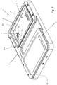
- FIG. 1 it can be seen that there is shown a system 1 according to a preferred embodiment of the present invention, which makes it possible to implement both the step of producing the negative prints of the two feet of a person and the step of forming the soles.
- the system 1 comprises a frame 2, two sole forming devices 3 according to a preferred embodiment of the present invention, a vacuum source 4 (visible on the Figures 9 and 13 ), control means of the latter (not shown), and two sets of imprinter pockets 5.
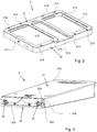
- the frame 2 which is shown alone, is in the form of a shell-like hollow part, comprising an upper part 21 generally flat and from the edge of which extends towards at the bottom a side skirt 22. This piece is closed by a closure plate (not shown) attached to the free edge of the side skirt 22.
- the upper portion 21 comprises two openings 211 each delimiting a compartment, also designated by the reference numeral 211, for receiving a sole forming device 3.
- the openings 211 are rectangular, larger in size than the sets of fingerprint pockets 5, and face the interior space of the frame 2.
- the two openings 211 are each surrounded by an edge region 212 of the upper portion 21 and are further separated, in the longitudinal direction of the system 1, by a central region 213 of the upper part 21 which is slightly recessed.
- the upper portion 21 also has two pairs of first through holes 214 along a longitudinal edge of the frame 2 and two pairs of second through holes 215 along the opposite longitudinal edge, with each pair in the vicinity of a transverse edge of a respective opening 211.
- the function of the through holes 214, 215 will be explained below.
- the frame 2 is made of rigid material, such as plastic.
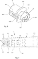
- a fingerprint pocket assembly 5 according to a preferred embodiment of the present invention will now be described with reference to Figures 3 to 7 .
- the fingerprint pocket assembly 5 comprises a fingerprint pocket 51 and a connection block 52.
- the fingerprint pocket 51 is similar to the prior art fingerprint pockets and will not be described in more detail here. Suffice it to say that the impinger pocket 51 has an upper face 510 in which the negative impression will be made, and in an axial end wall 511, two through holes symmetrical with respect to the vertical median longitudinal plane of the pocket. of fingerprint 51.
- connection block 52 serves to establish fluid communication between the interior space of the scavenger pocket 51 and the vacuum source 4, to allow the establishment of a vacuum inside the scavenger pocket 51. for taking a negative impression, and the fluidic communication between the forming space, which will be described in more detail below, and the vacuum source 4, for the establishment of a vacuum in the space of forming for the vacuum forming of the sole.
- the connecting block 52 is a longitudinal piece of generally parallelepipedic contour, thus having a first vertical longitudinal side 521 facing the impinger pocket 51, and a second vertical longitudinal side 522 opposite said first longitudinal side 521 and two vertical lateral sides 523, 524.
- a groove 525 extends inwardly from the second longitudinal side 522, from one lateral side 523 to the other 524, onto which it opens by forming an orifice 526.
- Two through holes extend from the bottom of the groove 525 to the first side 521, one in the vicinity of the lateral side 523 and the other in the vicinity of the lateral side 524. Each of these two through holes is respectively aligned respectively with one of the through holes in the fingerprint pocket 51.
- a blind end piece 53 is mounted in the through hole in the vicinity of the lateral side 524, while an open end 54 is mounted in the through hole in the vicinity of the lateral side 523.
- the blind end 53 comprises a cylindrical portion 531 closed at one end and whose other end has a flange 532 in contact with the bottom of the groove 525.
- a horizontal slot 533 extends inwardly from the flange 532.
- the slot 533 comprises a rounded central portion 533a, which terminates in a hole 533b communicating with the closed end of the cylindrical portion 531, and two oblong side portions 533c which each end with a transverse face 533d forming the bottom of the slot 533.
- a connector 55 is mounted in the blind end 53.
- the connector 55 comprises a cylindrical portion 551 received in the rounded central portion 533a of the slot 533, a flange 552 bearing against the outer face of the flange 532, and a connecting portion 553 configured to receive a connection piece. 40a as will be explained below.
- a through hole 554 extends from the end of the cylindrical portion 551 to the connecting portion 553.
- the length of the cylindrical portion 551 of the connector 55 is less than the depth of the slot 533, so that a gap is left between the free end of the cylindrical portion 551 and the hole 533b, and thus the bottom of the slot 533, which allows to create a lateral passage to each of the two oblong portions 533c of the slot 533.
- the flange 552 is dimensioned so as to leave at least partially free the oblong portions 533c at the level of the flange 532, which therefore communicate with the groove 525, and in particular the orifice 526.
- the open end 54 comprises a cylindrical portion 541 closed at one end and whose other end has a flange (not visible) in contact with the bottom of the groove 525, similarly to the blind end 53.
- An axial hole (Not visible) extends from the flange to the closed end and a plurality of radial holes 542 extend from the outer surface of the cylindrical portion 541 and open to the axial hole.
- a connector 55 is also mounted in the open end 54 and the through hole 554 of the connector 55 communicates with the axial hole of the open end 54.
- the cylindrical portion 541 extends inside the impinger pocket 51, and that the connection block 52 is attached to the impinger pocket 51 by bonding, for example by gluing, flanges 532 of the end pieces 53, 54 against the axial end wall 511 of the impression pocket, and that for this purpose a ring 512 is embedded in said axial end wall 511 to allow a solid connection between the connection block 52 and the impinger pocket 51.
- the ring 512 has two orifices which will each be aligned with a respective one of the two through-holes extending from the bottom of the groove 525 and, consequently, the two through-holes that are present.
- the impinger pocket 51 and mentioned above are each formed by an orifice provided in the rod 52 and by two orifices formed on either side of the rod 52 and facing said through hole.
- the sole forming device 3 according to a preferred embodiment of the present invention, hereinafter referred to as device 3, will now be described for the sake of brevity, with reference to FIGS. Figures 1 and 8 to 12 .
- the device 3 comprises a tray 31 and a lid 32. On the Figure 1 , only a cover 32 has been shown, and on the Figure 8 no cover 32 has been shown and only one set of fingerprint pocket 5 has been shown.
- the tray 31 is rectangular and comprises a bottom 310 and a side casing 311 whose free end is folded outwardly to form a flange 312.
- Each tray 31 is sized to be introduced inside the frame 2 by the intermediate of respective opening 211, and is dimensioned to be fixed to the frame 2 by attachment, by any suitable means, such as by gluing, the flange 312 all around the edge region 212 of the respective opening 211.
- the depth of the tray 31, in other words the height of the side skirt 311, will be defined to be at least slightly greater than the maximum height of the imprinter bag assembly 5, so that the latter can be installed in the tray 31, resting on the bottom 310 of the tray 31, without the upper face 510 of the stamper pocket 51 is located above the flange 312.
- the lateral casing 311 comprises, in a wall parallel to the longitudinal direction of the system 1, two through-holes positioned so as to be opposite the connectors 55 when the pulse-pocket assembly 5 is installed in the tank 31. Each of these two through-holes is crossed by a connecting piece 40a, 40b, a portion 401 protrudes into the tray 31 and another part 402 is outside the tray 31 and is connected to the vacuum source 4.
- the tray 31 is made of a flexible and waterproof material, preferably silicone.
- the cover 32 includes a frame 320 and a membrane 321 extending therethrough.
- the frame 320 is rigid and rectangular, of dimensions at least slightly greater than those of the tray 31.
- the membrane 321 forms the support wall according to the present invention, and is thus made of a flexible material, waterproof and expandable, preferably silicone.
- the membrane 321 may be fixed by any appropriate means to the frame 320.
- the edge region 321a of the membrane 321 can be folded inwardly around a rectangular annular rod 322, to be sandwiched between the annular rod 322 and a lower side 320a of the frame 320.
- the annular ring 322 is screwed to the frame 320 by a plurality of screws distributed along the frame 320 and which are screwed into the annular rod 322 through the respective screw holes provided in the frame 320 and crossing the edge region 321a of the membrane 321.
- this lower side 320a is formed by an insert L 323, the long arm 323a is applied against a recessed face 320b of the frame 320 and is fixed by screws 324, outer side of the frame 320 , and whose short leg 323b extends inside a groove 320c correspondingly provided in the frame 320, inner side of the frame 320.
- each cover 32 can be mounted both removably on the frame 2 and pivotally about a horizontal pivot axis parallel to the longitudinal direction of the frame 2.
- Each cover 32 can thus be pivoted between an open position, in which it is raised to give access to the tray 31, and a closed position in which it closes the tray 31, with the frame 320 resting against the edge 312 of the bin 31, as can be seen on the Figure 12 .
- the cover 32 In the closed position, the cover 32 rests at its free end on two bearing pads 217 projecting out of the through holes 215 of the frame 2.
- this support of the frame 320 can be done directly, namely that the lower side 320a of the frame 320 comes directly in contact with the edge 312 of the tray 31, or be done indirectly, namely that parts are interposed between said lower side 320a and said edge 312.
- a portion of the membrane 321 is sandwiched between the frame 320 and the edge 312 of the tray 31, here the portion which is in the vicinity of the annular ring 322, inner side relative thereto.
- the frame 320 or the membrane 321 comes into direct contact on the edge region 212 of the frame 2 in which the tray 31 is fixed in another way to the frame 2, for example with the edge 312 of the tray 31 under the upper part 21 of the frame 2.
- this support is waterproof.
- this sealing can be ensured by the sole weight of the cover 32, which is sufficiently high, but it could be provided means for tightening the cover 32 against the frame 2, by example using magnets, straps, flanges, etc.
- the tank 31 and the cover 32 together define a chamber 6 in which the pocket pocket assembly 5 is installed.
- the chamber 6 communicates with the outside only through a passage formed by the orifice 526 in the lateral side 524 of the connection block 52, the groove 525 of the connector 55, the horizontal slot 533 of the blind end piece 53, then the through hole 554 of the connector 55 and the connection endpiece 40a.
- the portion 401 of the connector 40a is received in the through hole 554 of the connector 55 when the imprinter pocket assembly 5 is properly installed in the tray 51.
- the connector 55 mounted in the connector open 54 similarly receives the additional connecting piece 40b.
- Each connecting end 40a, 40b is connected to the vacuum source 4 which will now be described with reference to Figures 9 and 13 .
- the vacuum source 4 comprises two vacuum pumps P1, P2 each having four pump heads.
- Each vacuum pump P1, P2 is connected to a respective connection piece 40a by a vacuum circuit for forming and to an additional connecting piece 40b respectively by a vacuum circuit for taking an impression.
- Each vacuum circuit for forming comprises a plurality of ducts connecting the suction orifices of three heads of the respective vacuum pump P1, P2 to a main pipe CP connected at one end to a connecting piece 40a and the other end to the other connection tip 40a.
- Upstream (in the suction direction of the air) of each vacuum pump P1, P2 is provided a check valve CA1, CA2 and upstream of each check valve CA1, CA2 is provided a solenoid valve 3/2, spring-loaded in the position in which the vacuum pump P1, P2 is at the exhaust.
- This solenoid valve is designated by the reference sign EV1, EV2.
- each of these three heads of each vacuum pump P1, P2 is connected to the open air by an exhaust pipe in which is placed an exhaust silencer S.
- Each solenoid valve EV1, EV2 is associated with an on / off switch I1, I2, downstream of which is mounted a light-emitting diode DEL1, DEL2 and a diode D1, D2 allowing the current from the respective switch I1, I2, which current is used to to operate the vacuum pumps P1, P2.
- This arrangement also has the advantage of causing the vacuum to be established in a respective chamber 6 by the two vacuum pumps P1, P2, which makes it possible to reach in the chamber 6 a sufficient vacuum value for the support of the membrane 321 against the soleplate according to the latter, and, in the case of a thermoformable soleplate, in a sufficiently rapid manner so that this value of vacuum is reached while the soleplate has not yet cooled and can therefore be deformed by the 321 membrane.
- This assembly also makes it possible, if desired, to establish a vacuum simultaneously in the two chambers 6 if it is desired to form two soles simultaneously.
- Each vacuum circuit for taking the impression comprises a first duct connecting the suction orifice of the fourth head of the vacuum pump P1, P2 respectively to an additional connecting piece 40b and a second duct connecting to the open air the exhaust port.
- a 4/2 spring return solenoid valve in the position in which the suction port is in communication with the additional connection piece 40b and the exhaust port is at the exhaust, is provided upstream of the suction port / downstream of the exhaust port.
- This solenoid valve is designated by the reference sign EV3.
- a silencer is placed on the exhaust line downstream of the solenoid valve EV3.
- a 2/2 spring return solenoid valve in the closed position is connected in parallel with the solenoid valve EV3 so as to connect, in the open position, the conduit connecting the solenoid valve EV3 to the additional connecting piece 40b and the line exhaust leading to the open air, and in which is provided, downstream, a silencer S.
- the vacuum pumps P1, P2 when actuated, they can establish a vacuum in the impinger pocket 51. It is also possible to break the vacuum inside the impinger pocket 51 while it is still installed in the tank 31, by controlling the solenoid valves EV3 and EV4 to place them in their second position, in which the suction port and the exhaust port of the fourth head are respectively connected to the exhaust line and the pipe leading to the additional connecting piece 40b, which pipe is also exhausted by the solenoid valve EV4.
- the system 1 allows the practitioner to perform all of the manufacture of one or two soles without handling the imprint pockets 5.
- each pulse bag assembly 5 placed in a respective tray 31, if they are not already there, where the pouch pouch assemblies 5 automatically connect to the vacuum source 4 via the Vacuum circuits for impression taking and vacuum circuits for forming.
- the patient places one foot on a fingerprint pocket 51, the other foot resting on the central region 213 of the frame 2.
- the practitioner models the fingerprint pocket 51 to obtain the desired negative impression, then place a thermoformable insole, previously heated, in the negative impression.
- the practitioner then controls the vacuum source 4 to make the vacuum in the fingerprint pocket 51 and thus freeze the negative impression.
- a vacuum distributor 7, which is here in the form of a wire-type spacing element, such as for example a chain 71 shown schematically only on the Figure 1 , one end of which is connected to a half-moon piece 72 ( Figures 1 and 12 ), the chain 71 passing through a hole provided for this purpose in the frame 2.
- the practitioner can enter the chain 71 by the half-moon piece 72, pull it, then place it in the vicinity of the front end of the soleplate so that the chain 71 extends across the transition region between the negative imprint and the portion of the upper face 510 of the tracer pocket 51 surrounding the negative imprint. This ensures the continuity of the vacuum between the chamber 6 and the vacuum source 4 throughout the vacuum forming step.
- the vacuum is maintained for a period of time sufficient for the sole to be shaped and cooled.
- the practitioner controls the vacuum source 4 to put the chamber 6 in the exhaust and thus break the vacuum established in the chamber 6, then he can raise the cover 32 and remove the negative footprint consistent and cooled.
- the practitioner also puts the pulse pocket assembly 5 in the exhaust by controlling the vacuum source 4, either before or after removing the sole of the negative impression.
- a tray 31 in a flexible and waterproof material therefore ensures the maintenance of the shape of the negative impression even when the imprinter pocket 5 is likely to deform because the vacuum established inside of the latter to fix the negative impression would not be sufficient to prohibit a possible deformation due to the greater pressure applied to the imprinter pocket 5 when establishing the vacuum in the chamber 6.
Landscapes
- Health & Medical Sciences (AREA)
- Engineering & Computer Science (AREA)
- General Health & Medical Sciences (AREA)
- Public Health (AREA)
- Life Sciences & Earth Sciences (AREA)
- Epidemiology (AREA)
- Mechanical Engineering (AREA)
- Vascular Medicine (AREA)
- Biomedical Technology (AREA)
- Heart & Thoracic Surgery (AREA)
- Orthopedic Medicine & Surgery (AREA)
- Nursing (AREA)
- Animal Behavior & Ethology (AREA)
- Veterinary Medicine (AREA)
- Biophysics (AREA)
- Chemical & Material Sciences (AREA)
- Materials Engineering (AREA)
- Wood Science & Technology (AREA)
- Orthopedics, Nursing, And Contraception (AREA)
- Footwear And Its Accessory, Manufacturing Method And Apparatuses (AREA)
Applications Claiming Priority (1)
| Application Number | Priority Date | Filing Date | Title |
|---|---|---|---|
| FR1770902A FR3070259B1 (fr) | 2017-08-30 | 2017-08-30 | Procede de formage de semelle dans une empreinte negative, et dispositif et systeme de formage de semelle pour sa mise en œuvre |
Publications (2)
| Publication Number | Publication Date |
|---|---|
| EP3459507A2 true EP3459507A2 (de) | 2019-03-27 |
| EP3459507A3 EP3459507A3 (de) | 2019-06-12 |
Family
ID=60302399
Family Applications (1)
| Application Number | Title | Priority Date | Filing Date |
|---|---|---|---|
| EP18191605.7A Withdrawn EP3459507A3 (de) | 2017-08-30 | 2018-08-30 | Formverfahren einer sohle in einem negativabdruck, und vorrichtung und system zum formen einer sohle für dessen umsetzung |
Country Status (2)
| Country | Link |
|---|---|
| EP (1) | EP3459507A3 (de) |
| FR (1) | FR3070259B1 (de) |
Family Cites Families (4)
| Publication number | Priority date | Publication date | Assignee | Title |
|---|---|---|---|---|
| DE1234355B (de) * | 1963-12-21 | 1967-02-16 | Bruno Hullmann | Einrichtung zur Herstellung von orthopaedischen Einlagen u. dgl. |
| FR2722390B1 (fr) * | 1994-07-13 | 1996-08-23 | Sidas Sa | Procede de formage de semelles et dispositif de mise en oeuvre |
| US20040094864A1 (en) * | 2002-11-18 | 2004-05-20 | Franzene Brian J | Custom shoe sole manufacturing system |
| WO2017007533A1 (en) * | 2015-07-06 | 2017-01-12 | Light Composites Llc | Light-cured composite insole |
-
2017
- 2017-08-30 FR FR1770902A patent/FR3070259B1/fr active Active
-
2018
- 2018-08-30 EP EP18191605.7A patent/EP3459507A3/de not_active Withdrawn
Also Published As
| Publication number | Publication date |
|---|---|
| FR3070259A1 (fr) | 2019-03-01 |
| EP3459507A3 (de) | 2019-06-12 |
| FR3070259B1 (fr) | 2021-01-15 |
Similar Documents
| Publication | Publication Date | Title |
|---|---|---|
| CA2931404C (fr) | Appareil electrique de chauffage et/ou de cuisson d'aliments a la vapeur | |
| EP3897940A1 (de) | Herstellungsvorrichtung zur herstellung einer zusammensetzung aus einer mischung von formulierungen | |
| FR2922427A1 (fr) | Cellule gonflable, procede de fabrication et dispositif de support en comportant | |
| FR3090399A1 (fr) | Appareil de fabrication, machine à mélange et/ou dispositif de réception pour la fabrication d’une composition à partir d’un mélange de formulations | |
| WO2012049429A2 (fr) | Dispositif de nettoyage d'une prothese auditive | |
| CA2208434A1 (fr) | Procede et dispositif de chauffage d'une garniture interieure de chaussure | |
| EP1995502B1 (de) | Pneumatisches Regelventil und Energiespeicher und Stützvorrichtung | |
| EP3459507A2 (de) | Formverfahren einer sohle in einem negativabdruck, und vorrichtung und system zum formen einer sohle für dessen umsetzung | |
| EP1256431B1 (de) | Spritzgiessmaschine für Formteile aus Elastomer | |
| EP0507709A1 (de) | Verfahren und Vorrichtung zum Bestimmen der Schuhgrösse und Apparat zum Bestimmen der Grösse des vorderen Teils eines Schuhs | |
| EP3413929B1 (de) | Vorrichtung zur reinigung eines hörgeräts | |
| FR2542983A1 (fr) | Ensemble compose d'une poche d'air, d'une pompe et d'une soupape, destine a etre incorpore a des chaussures, notamment des chaussures de ski | |
| EP0310531A1 (de) | Verfahren und Vorrichtung zur Gewinnung von korrigierten Abdrücken der Füsse zur Herstellung von korrigierenden Schuhsohlen | |
| FR2513551A1 (fr) | Appareil pour preparer des moules de fonderie en sable durci par un gaz | |
| EP3771546A1 (de) | Vorrichtung zur ummantelung einer hülle auf einer hohlstruktur, und entsprechendes verfahren | |
| EP0493197B1 (de) | Verfahren zum Formen eines fliessfähigen Materials, insbesondere Seifen, und transparente oder durchscheinende Seifen | |
| EP4076263B1 (de) | Anordnung mit einer implantierbaren medizinischen vorrichtung und verpackung für diese vorrichtung | |
| FR2609448A3 (fr) | Dispositif de prelevement, sur piles de plateaux, de plateaux individuels flexibles | |
| FR2682028A1 (fr) | Procede, dispositif et appareillage pour l'obtention d'une empreinte de la surface d'un objet ou d'une partie du corps. | |
| EP1813164B1 (de) | Vorrichtung zur Herstellung eines Schuhartikels | |
| EP4076270B1 (de) | Verfahren zum entleeren einer implantierbaren medizinischen vorrichtung | |
| FR2763561A1 (fr) | Systeme de gonflage sterile pour un sac a paroi souple ferme | |
| FR2981546A1 (fr) | Perfectionnement a des procedes et dispositifs pour obtenir des empreintes de plantes de pieds afin de fabriquer des semelles correctrices. | |
| BE893770A (fr) | Appareil pour la fabrication de galettes de cereales expansees | |
| FR2597833A1 (fr) | Procede et dispositif pour le thermoscellage de barquettes a atmosphere interne gazeuse |
Legal Events
| Date | Code | Title | Description |
|---|---|---|---|
| PUAI | Public reference made under article 153(3) epc to a published international application that has entered the european phase |
Free format text: ORIGINAL CODE: 0009012 |
|
| AK | Designated contracting states |
Kind code of ref document: A2 Designated state(s): AL AT BE BG CH CY CZ DE DK EE ES FI FR GB GR HR HU IE IS IT LI LT LU LV MC MK MT NL NO PL PT RO RS SE SI SK SM TR |
|
| AX | Request for extension of the european patent |
Extension state: BA ME |
|
| PUAL | Search report despatched |
Free format text: ORIGINAL CODE: 0009013 |
|
| AK | Designated contracting states |
Kind code of ref document: A3 Designated state(s): AL AT BE BG CH CY CZ DE DK EE ES FI FR GB GR HR HU IE IS IT LI LT LU LV MC MK MT NL NO PL PT RO RS SE SI SK SM TR |
|
| AX | Request for extension of the european patent |
Extension state: BA ME |
|
| RIC1 | Information provided on ipc code assigned before grant |
Ipc: A61F 5/14 20060101AFI20190506BHEP Ipc: A43B 7/14 20060101ALI20190506BHEP Ipc: A43D 1/02 20060101ALI20190506BHEP Ipc: A43B 17/00 20060101ALI20190506BHEP Ipc: A43B 7/28 20060101ALI20190506BHEP |
|
| STAA | Information on the status of an ep patent application or granted ep patent |
Free format text: STATUS: THE APPLICATION IS DEEMED TO BE WITHDRAWN |
|
| 18D | Application deemed to be withdrawn |
Effective date: 20191213 |