EP3458919B1 - Robotergestütztes objektlernendes visionssystem - Google Patents
Robotergestütztes objektlernendes visionssystem Download PDFInfo
- Publication number
- EP3458919B1 EP3458919B1 EP17798895.3A EP17798895A EP3458919B1 EP 3458919 B1 EP3458919 B1 EP 3458919B1 EP 17798895 A EP17798895 A EP 17798895A EP 3458919 B1 EP3458919 B1 EP 3458919B1
- Authority
- EP
- European Patent Office
- Prior art keywords
- channel value
- contour
- features
- pixels
- image
- Prior art date
- Legal status (The legal status is an assumption and is not a legal conclusion. Google has not performed a legal analysis and makes no representation as to the accuracy of the status listed.)
- Active
Links
- 238000000034 method Methods 0.000 claims description 111
- 230000000007 visual effect Effects 0.000 claims description 104
- 238000012549 training Methods 0.000 claims description 66
- 230000008569 process Effects 0.000 claims description 60
- 238000013507 mapping Methods 0.000 claims description 32
- 230000033001 locomotion Effects 0.000 claims description 16
- 238000004364 calculation method Methods 0.000 claims description 8
- 238000012805 post-processing Methods 0.000 claims description 8
- 230000003213 activating effect Effects 0.000 claims description 2
- 230000004807 localization Effects 0.000 claims description 2
- 238000012545 processing Methods 0.000 description 89
- 230000006870 function Effects 0.000 description 17
- 238000003860 storage Methods 0.000 description 16
- 239000000284 extract Substances 0.000 description 10
- 235000002595 Solanum tuberosum Nutrition 0.000 description 8
- 244000061456 Solanum tuberosum Species 0.000 description 8
- ZYXYTGQFPZEUFX-UHFFFAOYSA-N benzpyrimoxan Chemical compound O1C(OCCC1)C=1C(=NC=NC=1)OCC1=CC=C(C=C1)C(F)(F)F ZYXYTGQFPZEUFX-UHFFFAOYSA-N 0.000 description 8
- 238000004891 communication Methods 0.000 description 8
- 238000010586 diagram Methods 0.000 description 7
- 238000004458 analytical method Methods 0.000 description 6
- 238000004519 manufacturing process Methods 0.000 description 6
- 230000003287 optical effect Effects 0.000 description 6
- 238000012856 packing Methods 0.000 description 6
- 235000015895 biscuits Nutrition 0.000 description 5
- 238000003066 decision tree Methods 0.000 description 5
- 235000013311 vegetables Nutrition 0.000 description 5
- 238000004590 computer program Methods 0.000 description 4
- 238000013461 design Methods 0.000 description 4
- 238000006073 displacement reaction Methods 0.000 description 4
- 238000010191 image analysis Methods 0.000 description 4
- 238000012804 iterative process Methods 0.000 description 4
- 239000002994 raw material Substances 0.000 description 4
- 150000001875 compounds Chemical class 0.000 description 3
- 235000014510 cooky Nutrition 0.000 description 3
- 238000013500 data storage Methods 0.000 description 3
- 238000009826 distribution Methods 0.000 description 3
- 230000006872 improvement Effects 0.000 description 3
- 239000000463 material Substances 0.000 description 3
- 238000005259 measurement Methods 0.000 description 3
- 239000000203 mixture Substances 0.000 description 3
- 235000012015 potatoes Nutrition 0.000 description 3
- 238000003908 quality control method Methods 0.000 description 3
- 238000013459 approach Methods 0.000 description 2
- 238000003491 array Methods 0.000 description 2
- 238000013145 classification model Methods 0.000 description 2
- 238000005516 engineering process Methods 0.000 description 2
- 238000003709 image segmentation Methods 0.000 description 2
- 239000004615 ingredient Substances 0.000 description 2
- 230000001795 light effect Effects 0.000 description 2
- 239000003550 marker Substances 0.000 description 2
- 230000007246 mechanism Effects 0.000 description 2
- 238000000275 quality assurance Methods 0.000 description 2
- 238000012546 transfer Methods 0.000 description 2
- 241000249058 Anthracothorax Species 0.000 description 1
- 235000004936 Bromus mango Nutrition 0.000 description 1
- 235000014826 Mangifera indica Nutrition 0.000 description 1
- 235000009184 Spondias indica Nutrition 0.000 description 1
- 238000013528 artificial neural network Methods 0.000 description 1
- 238000006243 chemical reaction Methods 0.000 description 1
- 239000003086 colorant Substances 0.000 description 1
- 238000010276 construction Methods 0.000 description 1
- 238000013135 deep learning Methods 0.000 description 1
- 238000013136 deep learning model Methods 0.000 description 1
- 235000013399 edible fruits Nutrition 0.000 description 1
- 238000000605 extraction Methods 0.000 description 1
- 235000013305 food Nutrition 0.000 description 1
- 238000010348 incorporation Methods 0.000 description 1
- 238000012986 modification Methods 0.000 description 1
- 230000004048 modification Effects 0.000 description 1
- 239000004065 semiconductor Substances 0.000 description 1
- 230000011664 signaling Effects 0.000 description 1
- 235000011888 snacks Nutrition 0.000 description 1
- 230000003068 static effect Effects 0.000 description 1
- 239000004575 stone Substances 0.000 description 1
- 238000012360 testing method Methods 0.000 description 1
- 238000013519 translation Methods 0.000 description 1
- 210000000707 wrist Anatomy 0.000 description 1
Images


Classifications
-
- B—PERFORMING OPERATIONS; TRANSPORTING
- B25—HAND TOOLS; PORTABLE POWER-DRIVEN TOOLS; MANIPULATORS
- B25J—MANIPULATORS; CHAMBERS PROVIDED WITH MANIPULATION DEVICES
- B25J9/00—Programme-controlled manipulators
- B25J9/16—Programme controls
- B25J9/1694—Programme controls characterised by use of sensors other than normal servo-feedback from position, speed or acceleration sensors, perception control, multi-sensor controlled systems, sensor fusion
- B25J9/1697—Vision controlled systems
-
- B—PERFORMING OPERATIONS; TRANSPORTING
- B25—HAND TOOLS; PORTABLE POWER-DRIVEN TOOLS; MANIPULATORS
- B25J—MANIPULATORS; CHAMBERS PROVIDED WITH MANIPULATION DEVICES
- B25J9/00—Programme-controlled manipulators
- B25J9/16—Programme controls
- B25J9/1628—Programme controls characterised by the control loop
- B25J9/163—Programme controls characterised by the control loop learning, adaptive, model based, rule based expert control
-
- G—PHYSICS
- G06—COMPUTING; CALCULATING OR COUNTING
- G06T—IMAGE DATA PROCESSING OR GENERATION, IN GENERAL
- G06T1/00—General purpose image data processing
- G06T1/0014—Image feed-back for automatic industrial control, e.g. robot with camera
-
- G—PHYSICS
- G05—CONTROLLING; REGULATING
- G05B—CONTROL OR REGULATING SYSTEMS IN GENERAL; FUNCTIONAL ELEMENTS OF SUCH SYSTEMS; MONITORING OR TESTING ARRANGEMENTS FOR SUCH SYSTEMS OR ELEMENTS
- G05B2219/00—Program-control systems
- G05B2219/30—Nc systems
- G05B2219/40—Robotics, robotics mapping to robotics vision
- G05B2219/40565—Detect features of object, not position or orientation
Definitions
- the present invention in some embodiments thereof, relates to methods and systems for generating and using dataset mapping visual features of objects and, more particularly, but not exclusively, for robot assisted object learning by visual systems.
- robotic machines are widely deployed in a variety of industrial applications. Many of those applications utilize robotic machines working together as a robotic team. Deploying robotic machines requires the assignment of tasks to be performed by the robotic machines. There are different known methods to define the task for the robotic machine. Typically, the methods require a collaboration effort of at least a computer programming engineer and a process engineer. Such team needs to setup the task using basic machine movement instructions, and then fine tune these motions in a step by step process until the new robotic machine task is refined enough for real life operation.
- a robotic machine has to have capability of identifying objects in order to perform relevant tasks related to an object.
- Vision systems with different types of sensors combined with processing units executing image analysis software are widely used to identify objects in an operational scene.
- the sensors and the dedicated software are designed and set to determine the physical location of the object relative to the sensors and/or to other objects or equipment in the scene.
- Examples of such applications are vision systems used to assist robots in performing tasks with objects that are at reach and whose positions are not fixed or not previously known.
- An example of one of the methods known in the industry, of teaching a robotic machine a task to be performed, is based on learning by demonstration.
- Such method includes steps of collecting a sequence of images showing a demonstrator performing a manipulation of an object.
- An analysis is performed on the images and identification of the demonstrator body parts while manipulating the object is conducted.
- robotic machine movements are defined to perform the demonstrated task and relevant motion command for instructing the robotic machine to perform the task is generated.
- one embodiment is a method that captures a first image of at least one object with an image capture device, processes the first captured image to find an object region based on a reference two-dimensional model and determines a three-dimensional pose estimation based on a reference three-dimensional model that corresponds to the reference two-dimensional model and a runtime three-dimensional representation of the object region where a point-to-point relationship between the reference three-dimensional models of the object and the runtime three-dimensional representation of the object region is not necessarily previously known.
- two-dimensional information or data is used to segment an image and three-dimensional information or data used to perform three-dimensional pose estimation on a segment of the image.
- US Patent Number 8923602 B2 teaches a visual guidance and recognition system requiring no calibration.
- One embodiment of the system comprises a servo actuated manipulator configured to perform a function, a camera mounted on the face plate of the manipulator, and a recognition controller configured to acquire a two dimensional image of the work piece.
- the manipulator controller is configured to receive and store the face plate position at a distance "A" between the reference work piece and the manipulator along an axis of the reference work piece when the reference work piece is in the camera's region of interest.
- the recognition controller is configured to learn the work piece from the image and the distance "A".
- a work piece is recognized with the system, and the manipulator is accurately positioned with respect to the work piece so that the manipulator can accurately perform its function.
- US Patent Application Publication Number 2012/053728A1 teaches an object-learning robot and corresponding method.
- the robot comprises a gripper for holding an object to be learned to the robot; an optical system having a field of view for introducing the object to the robot and for observing the gripper and the object held by the gripper ; an input device for providing an object identity of the object to be learned to the robot; a controller for controlling the motion of the gripper according to a predetermined movement pattern; and an image processing means for analyzing image data obtained from the optical system identifying the object for association with the object identity. This enables the robot to learn the identity of new objects in a dynamic environment, even without an offline period for learning.
- a method for generating a dataset mapping visual features of each of a plurality of different objects (105). For each of the plurality of different objects (105): conducting a plurality of iterations, wherein each iteration comprising: instructing either a robotic system (109) to move an arm holding a respective the object (105) to a next position of a plurality of different positions in front of at least one sensor, or a mechanical device equipped with at least one sensor to move to a next position of a plurality of different positions in a way that the object is kept in the field of view of the at least one sensor to be captured from different angles, distances and aspects.
- the post-processing process comprises: analyzing the visual features stored in the mapping dataset of the said object such that each visual feature is analyzed and considered of whether the feature uniquely identifying the object by comparing each visual feature of the object with relevant features of previously stored datasets of previously trained objects wherein visual features identified as not relevant are marked as such, and wherein when no visual feature is found to identify such uniqueness, such that the visual features of the object matches the relevant features of previously stored datasets of previously trained objects and in those previous datasets it is defined that the relevant features are enough to uniquely identify those previously trained objects, activating other visual features of those previous training sets such that they can uniquely identify the previously trained objects in regards to the object, continuing the post-processing process in an iterative way until finding unique visual features in each of the previously trained objects and the object and outputting the mapping dataset for enabling an identification and a localization of the plurality of different objects.
- the at least one image is captured by at least one of at least one camera (101, 102) and at least one sensor (101, 102) capturing a depth map image.
- the at least one visual feature is a member of a group consisting of a two dimensional, 2D, image feature and a three dimensional, 3D, image feature.
- the instructing includes at least one motion command that includes a step size and a step direction, wherein the step size and the step direction are one of pre-defined and randomly selected.
- the at least one visual feature is a member of a group consisting of contour, center of contour, number of contours, edges, color areas, size, perimeter and area.
- the at least one visual feature is a plurality of features including at least the features of:
- the blue channel value is a modified blue channel value calculated according to a weighted calculation of the blue channel value, the green channel value and the red channel value
- the green channel value is a modified green channel value calculated according to a weighted calculation of the blue channel value, the green channel value and the red channel value
- the red channel value is a modified red channel value calculated according to a weighted calculation of the blue channel value, the green channel value and the red channel value.
- the plurality of features further including the features of:
- the storing includes at least one of storing in the mapping dataset a quantified value of the at least one visual feature and storing of at least one characteristic of the object, provided by a user.
- the analyzing includes identifying in the at least one image at least one identifiable sign (106, 108) attached to at least one of the object (105) and a gripping part (107) of the robotic system (109).
- the robotic system is a conveyer (209) having a conveyer belt for moving the object.
- the analyzing includes identifying in the at least one image at least one identifiable sign (206) attached to the object (207).
- the method further comprising using the at least one processor to execute code instructions for adjusting said object positional information according to said positional information of said at least one identifiable sign.
- Implementation of the method and/or system of embodiments of the invention can involve performing or completing selected tasks manually, automatically, or a combination thereof. Moreover, according to actual instrumentation and equipment of embodiments of the method and/or system of the invention, several selected tasks could be implemented by hardware, by software or by firmware or by a combination thereof using an operating system.
- hardware for performing selected tasks according to embodiments of the invention could be implemented as a chip or a circuit.
- selected tasks according to embodiments of the invention could be implemented as a plurality of software instructions being executed by a computer using any suitable operating system.
- one or more tasks according to exemplary embodiments of method and/or system as described herein are performed by a data processor, such as a computing platform for executing a plurality of instructions.
- the data processor includes a volatile memory for storing instructions and/or data and/or a non-volatile storage, for example, a magnetic hard-disk and/or removable media, for storing instructions and/or data.
- a volatile memory for storing instructions and/or data
- a non-volatile storage for example, a magnetic hard-disk and/or removable media
- a network connection is provided as well.
- a display and/or a user input device such as a keyboard or mouse are optionally provided as well.
- the present invention in some examples thereof, relates to methods and systems for generating and using dataset mapping visual features of objects and, more particularly, but not exclusively, for robot assisted object learning by visual systems.
- a method for generating a dataset mapping visual features of each of a plurality of objects comprising: for each of a plurality of different objects: instructing a robotic system to move an arm holding a respective the object to a plurality of positions, and when the arm is in each of the plurality of positions: acquiring at least one image depicting the respective object in the position, receiving positional information of the arm in respective the position, analyzing the at least one image to identify at least one visual feature of the object in the respective position, and storing, in a mapping dataset, an association between the at least one visual feature and the positional information, and outputting the mapping dataset.
- 2D means a two dimensional positional attribute in space.
- 3D means a three dimensional positional attribute in space.
- the term "mechanical device” and the term “robot” or “robotic machine” mean a device that has at least one degree of freedom in motion, and has the capability of generating positional data.
- the term "object being trained to the system” means an object that the system went through learning process to be able to identify the object and identify its location.
- training set and “dataset” mean a set of records generated for an object being trained to the system. The two terms are used interchangeably along this document.
- the present invention in some examples thereof, identifies and locates objects without the need for involvement of technically qualified individuals and that may be adapted to any type of object that is trained and learned by the system.
- a method for training vision systems to identify and locate objects in their field of view consists of three main stages (1) a training stage in which a training set which maps visual features of different objects is generated, (2) a processing stage in which the training set is processed and identification and location data is generated, and (3) an identifying and locating stage for using the generated dataset to identify and locate objects.
- the generation of the dataset is based on capturing images of a known object by sensors of a vision system, from different positions. Then, combining 2D and 3D visual features detected by the vision system together with positional data reported by a mechanical device, such as a robot, that either has a fixed position relative to the object, a fixed position relative to the sensor or fixed position relative to both. The features and the associated position are recorded in a dataset for the specific object.
- the use of the dataset is based on capturing images of an unknown object by sensors of a vision system, from different positions. Then, extracting visual features of the object and comparing them to visual features of the datasets. When a match is found, the object identification and positional information is extracted from the dataset. This extracted information is then available for adapting the respective mechanical device or robotic machine to the identified object in the identified location.
- a system that consists of at least one sensor collects a plurality of images in a given scene where the target object or objects are present.
- the sensor may be a digital camera, an analog camera, a depth map sensor and the like.
- Target objects are, for example, biscuits, vegetables, boxes, wet wipes, manufactured goods, raw materials, semi-manufactured goods, packing boxes, cases, etc.
- the senor is physically attached to a mechanical device such as a robotic machine, and is connected to a vision processing unit.
- the mechanical device is also connected to a controller processing unit.
- vision processing unit and the controller processing unit may share hardware and/or software.
- a dataset mapping visual features is generated.
- the mechanical device's processing unit runs a software module that instructs the robot to move one step in a given or random direction and in a given or random step size.
- the vision processing unit runs a software module that collects one or more images from the sensor or sensors. The images depict the object. These images are analyzed and main visual features are extracted. Depth maps of the object may also be collected and analyzed.
- the mechanical device is a conveyer.
- the positional data is extracted by an encoder.
- the encoder may be an optical encoder, analog encoder, digital encoder or the like.
- the image analysis module of the vision processing unit may run the "openCV” function (Open Source Computer Vision which is a library of programming functions mainly aimed at real-time computer vision), e.g. "fitEllipse", “findContour” and “extractContours”.
- OpenCV Open Source Computer Vision
- These programming functions are mainly designed to segment and to recognize all the shapes present in an image. For example, “fitEllipse” compares each contour found in the image with approximations to ellipse-shaped contours, and then determines if shape is close enough to an ellipse.
- "findContour” defines a set of points that enclose one object in the image.
- an image depicting a pyramid, a cube and a potato the findContour identifies three contours, one for each of the objects in the image.
- the points of each contour delimit the object in the image.
- extractContours compares each contour with different shapes, and the determined shape is the one with area closest to the contour's area.
- extract 2D features of contours detected in the scene identifies features such as number of contours, contours' sizes, perimeters and areas and the like, calculated in pixel units.
- the image analysis module may also extract 3D features of these contours by adding derived data from depth maps and/or stereo vision systems. This adds features in real world 3D units as opposed to pixel units.
- the vision processing unit generates records for a dataset for the object, including the detected visual features and their respective quantified values.
- Modified red, green and blue channel (RGB) values may be a weighted calculation of the red, green and blue channel values calculated for each pixel.
- a "Y" feature may be calculated for each pixel:
- features indicating when a sum of modified color channel values divided by the sum of the modified other colors values is greater or smaller than a threshold are labeled as feature “a”, feature “b” and feature “c”.
- the position in space of the mechanical device is recorded as positional information by the controller processing unit.
- the positional information characterizes the 3D position of the mechanical device.
- the controller processing unit may generate a record with six variables: X, Y, Z corresponding to the 3D absolute position of the robot's end point; and Rx, Ry, Rz corresponding to the rotation of the robot's end point with regards to its axes X, Y, Z. These six values are generated as a record and stored by the controller processing unit.
- the record generated by the vision processing unit and the record generated by the controller processing are associated in the dataset by sharing a common value such as time stamp, or frame sequence. This association enables relating the records in following stages.
- Records may be stored in databases, flat files or other digital formats that are either accessible by both vision processing unit and controller processing unit or by each of the processing units independently.
- the controller processing unit generates a command to the mechanical device to move one step of predefined or random size and towards a predefined or randomly selected space direction.
- the vision processing unit retrieves images and depth maps from sensors, and then extracts 2D and 3D features. These images are now captured from a different position as the mechanical device is placed in a different position.
- the coordinates extracted from the mechanical device and the visual features detected from the images and/or depth maps are stored with an associating common value.
- the iterative process may be repeated until reaching a predefined number of iterations, a random number of iterations or calculated threshold.
- the threshold may be previously configured as number of iterations or as an area in space that must be scanned before finishing the process. "Montecarlo" techniques may be used to shorten the number of positions the mechanical device is moved to, before exiting the iterative process.
- the records generated during the iterations of the above process are denominated herein as a training set or dataset. Usually there may be one training set for each given object that the system is trained to identify and locate.
- the scene that is used for the training session may be set in a way that there is a common background color which differs from the color of the object being trained.
- the background color may be subtracted by image processing techniques from each image captured during the process. For example, a non-white object is placed in front of a white background or surface. This may assist and may improve the analysis process of identifying visual features extracted in each iteration.
- identifiable signs are attached to the surface of the object.
- Such signs may be a square colored sticker, a circle colored sticker, a bar code, a chess-board painted on the surface, a chess-board sticker and the like.
- the attachment of identifiable signs improves and assists the identification of visual features.
- identifiable signs are attached to scene objects placed in the training scene.
- scene objects are, for example a conveyer on which the trained object may be placed.
- three round stickers are attached to the surface of a conveyer.
- the round stickers form a sort of right triangle.
- the process described above is performed in a scene setup where the object being trained to the system is attached to the mechanical device being displaced, as opposed to being placed in a fixed position in the scene, as described above.
- the sensor or sensors are located in such way that part or all of mechanical device's reach is within field of view of the sensor or sensors.
- the process described above is performed in a scene setup where the object being trained to the system is placed on a static surface, as opposed to being placed on a moving conveyer, or held by a robot.
- the sensor or sensors are located in such way that the surface with the object is within field of view of the sensor or sensors.
- a software module scans the records of previous training sets and identifies the image visual features that are unique to the object associated to the current training set. This module may retrieve training sets from previous objects to calculate probability that any given feature uniquely identifies the object corresponding to the training set in question. For example, if previous objects have associated contour features that range in pixel sizes between a minimum iMin and a maximum iMax, and the current object has contours that exceeds iMax + iDelta, then the software determines that this feature alone is enough to uniquely identify the object corresponding to the current training set.
- the software module activates other image features, such as contour area or contour perimeter, of those previous training sets so that they may assist in uniquely identifying them now that a new object, with similar feature, is been trained into the system.
- the processing stage may also generate a hierarchical decision tree that allows to uniquely identifying a given object. For example, a regression tree may be used to feed the values associated in each training set to each object. The resulting tree is then used as a decision tree to classify previously trained objects in new scenes.
- a decision tree may be a dynamic decision tree which, for example has multiple decision nodes. As an example, a first node may be a decision based on the inquiry: "is the contour size bigger than nnnn".
- the decision flow may move for example to a second node where the inquiry is: "is the dominant color blue?" when, for example the answer is yes, the next node may be "what is the area of the object's contour?"
- the result of the decision tree may be an instruction such as "Look into database for such size of contours with dominant blue color and retrieve 3D properties".
- Records from different training sets are indexed by the contour's center feature. Records with same contour's center position (expressed as xy 2D pixel coordinates) from training sets corresponding to different objects may be present.
- the software module scans all previous training sets and extracts records sharing same 2D xy pixel coordinate values for the feature "contour center”. At this point there is a set of records for each unique xy pixel values, each set being composed of records from previous training sets that share same xy center pixel values for their feature "contour center”.
- the additional visual features associated with each record for an xy center position i.e.
- contour size in pixels, contour area in pixels, contour perimeter in pixels, etc. may be used to feed a regression tree that analyzes features of previous training sets sharing xy center positions.
- the regression tree generates a classification tree that assigns probabilities for each node that the center of a contour detected in a new future scene in this 2D xy pixel position belongs to a previously trained object. Similar classification tree may be generated using the approach above for each registered xy pixel position found in records for the feature "contour center".
- classification models are used for the above stage for achieving same goal as described above.
- Such other classification models may be neural networks and deep learning models or the like.
- an end user adds other visual features to the training sets based on known characteristics of the object being trained. For example, when a cube-like object is being trained into the system, and it is known to the user that the cube sides vary in sizes between 3cm and 3.3cm, this information may be registered into the system to enable the processing stage to calculate 3D dimensions, and the location of each edge, by combining the 2D detected features with the known measurements registered by the end user.
- an end user adds feature information to the training set.
- feature information may be a designation of a classification, like "good” object or "bad” object.
- Such manually added feature information of "good” and “bad” may be used in a process of classifying new objects that are inspected as “good” or “bad” based on the recorded datasets. This may be served for quality control processes.
- features may be classification information of the object.
- an object may be classified as a "cookie” and may further be classified as “cookie 1", or “cookie 2" etc.
- features like classification of objects as "within specification” or “outside specification” may allow automatic identification of objects within or outside specification in automatic manner, and then this identification is used for automatic sorting.
- potatoes as an example, the system marks anything that does not fall under the classification of "potato". For example, when a stone or strange object is found in the image, the system identifies that the object is not a potato and may send a sign or may stop the production or sorting line. Any object that does not look as a potato, according to the training set of potatoes, may not be considered as a potato and may be classified as "bad".
- a robot may remove the object.
- the object is marked on a screen of an operator.
- the sorting or production line is stopped.
- the sorting or production line is stopped until the object is removed, etc.
- the final stage corresponds to the process of identifying and locating objects in a scene using the data and assisted information generated in the two previous stages.
- the vision processing unit retrieves images from a sensor, in real-time or offline, and extracts image visual features such as contours, fitting shapes (i.e. fitEllipse), and the like.
- the software module retrieves from the stored training sets all the records that present a contour size and a contour center that is close or equal to the center of the contour that is detected in the image being analyzed.
- the software either assumes that the object in the image corresponds to the object in the training set, or it may retrieve additional features of the object that are found in the image and of the training set to validate that the object in the image is indeed the object of the training set.
- the positional information previously stored by the mechanical device is retrieved from the record and an estimation is performed as to the relative X,Y,Z position of the object with regards to the sensor. Additionally, an estimated X,Y,Z position relative to the first or last record created during the training set of that object may be retrieved. For example, if in a training stage the object was originally placed exactly in front of the center of the camera, and the match found in the training set corresponds to the image that was taken after either the sensor or object was displaced i,j,k cm in space, then this relative position can also be retrieved from the matching record in the training set for the current image.
- the retrieved identification and positional data is then reported or fed to additional software modules that may use the information to control a mechanical device. Such control may direct the mechanical device to move toward the detected object, or to avoid it. Optionally, an end user can be informed with the relative position of the object. Optionally, other applications are fed with the retrieved identification and positional data.
- At least one circular stickers is attached or is painted on the surface of the object being trained.
- the object is placed at the end point of a robot and in front of a digital camera, depth sensor or combination of them.
- the retrieved object positional information may include positional information of identifiable signs such as circular stickers.
- the position of the stickers in the retrieved positional data may be used to adjust the object positional information according to the positional information of the identifiable sign. For example, three identifiable signs, like markers, are placed over the plane of a conveyer or a table.
- the 3D position of the markers may be used to "logically" align the plane of the 3D image captured by the camera to a 3D logical image where the markers are aligned to the camera's plane. (i.e. rotate image so that point of one marker, located in position 100,200,300 is now set to 0,0,0 of camera coordinates, etc.). This adjustment of the positional information greatly assists in detecting the absolute and relative position of the object in training stage and in usage of training data.
- the object is placed in a fixed position and the sensor(s) are attached to the end point of the robot.
- the object is placed on a surface, and the location of the sensor is fixed.
- the circular stickers may be of a high-contrast color with respect to the background, in order to assist the image segmentation process.
- each digital camera and depth sensor sends the image to the vision processing unit.
- the vision processing unit extracts the pixel coordinates of the center of each sticker, as well as the length, measured in pixels, of the minor and major axes of the 2D ellipse corresponding to the circular stickers.
- a 2D ellipse is formed when a given circular sticker is not positioned exactly in front of the center of the camera and in a parallel plane, but is instead rotated or translated from that position, so that the shape of the circular sticker looks similar to that of an ellipse in a 2D image.
- One way to perform this process is, for example, to call the "Opencv” function "fitEllipse” function and/or combine it with the function "findContours”.
- a binary image may be created before running those functions, by segmenting only the color of the circular stickers or signs. As the robot moves during the training stage, each circular sticker or sign gets different values associated to them for x,y center coordinates, major and minor axes in pixels.
- the robot reports to the vision system the x,y,z coordinates of its end-point and the Rx,Ry,Rz rotation of its end point with regards to each axis. These coordinates are associated with the values extracted from the image of the circular stickers for each frame, and stored in a database for later retrieval.
- the following database table record is of stored results of one image frame: Circle A Circle B Circle C Robot X Robot Y Robot Z Robot Rx Robot Ry Robot Rz Center x1y1. Center x2y2. Center x3y3.
- three round stickers are used - Circle A, Circle B and Circle C.
- the coordinates of the center of each sticker are x1y1 for Circle A, x2y2 for Circle B and x3y3 for Circle C.
- the major axis of Circle A is m1 (measured in pixels), and the minor axis of Circle A is n1 (measured in pixels).
- the major axis of Circle B is m2 (measured in pixels), and the minor axis of Circle B is n2 (measured in pixels).
- the major axis of Circle C is m3 (measured in pixels), and the minor axis of Circle C is n3 (measured in pixels).
- N1, N2 and N3 are the coordinates of the Robot
- N4, N5 and N6 are the rotational position of the end point of the robot compared to the XYZ positional axes.
- a table such as the above includes a plurality of records corresponding to different images, each stores the coordinates, dimensions of major and minor axes of the three stickers with the corresponding N1-N6 parameters of the robot associated with the image taken and recorded.
- a search is performed through the table, looking for a record that most closely resembles the characteristics of current's frame Circles A, B and C. Once found, the associated robot coordinates (X, Y, Z, Rx, Ry and Rz) offer the 3D features of the object in the frame.
- 3D features correspond to the robot coordinates saved during the training stage when the object was in similar distance and rotation from the camera. They may be used directly, or they may be used to deduce other positions. For example, they may be used to calculate the relative displacement of current object's position with respect to a reference image frame where the object was placed in a plane parallel to the camera and at a known distance from it. They may also be used to calculate rotation and translation matrixes with respect to reference points in the scene or to the coordinate system of the robot. This may be either done at real-time frame collection stage, or in the processing stage. In the processing stage the results of these calculations may also be stored in the database, associated to the particular 2D features of each image frame.
- the training stage may be performed multiple times for the same object.
- the robot is instructed to move with the object attached to it, around an area just as defined in the training stage.
- the identification and location stage is run and an estimated position is obtained based on the original training set. This estimated position is then compared with the actual position of the robot in current training process being run, and the displacement between the current robot position and the one detected from the previous training set is estimated and stored.
- Another example of an application using the method is a scene where a robot learns from an orchestra director while the director directs the orchestra.
- the baton to be used by the orchestra director is fixed to a robotic arm's end point.
- the training stage is activated and the robot moves the baton in a cubic space while 2D features from the image and 3D features from the robot are retrieved and relationally stored. This can be conducted multiple times as described above.
- the sensors are placed in a way that the baton handled by the orchestra director is within their field of view.
- the director then directs the orchestra and the 2D features from the image, segmenting the orchestra baton will be translated to 3D features based on the identification and location stage as described herein.
- the 3D features are then stored and replayed by the robot, that can perform similar movements to the one performed by the orchestra director in order to bring the position of the baton to the same absolute or relative positions in similar time lapses to the ones detected during the orchestra direction.
- the relative position may be obtained by having one or more reference points in the scene that is captured by the sensors, for example, a marker on the location where some of the performers are sitting.
- Some examples of the present invention provide the ability to predict 3D aspects of an object based only on data of extracted features from images captured by a camera according to the combination of coordinates of a robot which is holding the object with 2D features extracted from the image.
- Some examples of the present invention provide a method that trains a system to automatically identify different objects in a working environment scenario and to identify the objects location. Common techniques usually require a significant tuning, adjusting and adapting procedures of the robotic machines when switching from one type of object to another, requiring the involvement of operators, engineers and/or programmers, as the system has to be re-calibrated, re-adjusted and adapted to the different object.
- the methods of some of the embodiments of the present invention reduce the effort to go through such procedures as the system is trained to identify automatically the new objects and automatically identify the object location, when a new object is presented to the system. Based on the process of training the system to identify an object the amount of effort, both computational effort and qualified team effort is reduced.
- Some of the embodiments of the present invention provide a significant improvement to the performance and precision of the prediction of the 3D pose features of an object, by using the training data as described above.
- Another improvement to the common manufacturing environment is the ability to combine robot's or conveyer's data with 2D features of objects, during training sessions.
- the information is then later used as base for improved operation of manufacturing line that may be using conveyers, like assembly and packing as quality assurance functions are applied in automatic manner even when different objects are examined by the system that identifies the object and identifies when the object is within the specification limitations or not. This eliminates the need to adapt the quality assurance functions whenever the object is changed.
- the present invention may be a system, a method, and/or a computer program product.
- the computer program product may include a computer readable storage medium (or media) having computer readable program instructions thereon for causing a processor to carry out aspects of the present invention.
- the computer readable storage medium can be a tangible device that can retain and store instructions for use by an instruction execution device.
- the computer readable storage medium may be, for example, but is not limited to, an electronic storage device, a magnetic storage device, an optical storage device, an electromagnetic storage device, a semiconductor storage device, or any suitable combination of the foregoing.
- Computer readable program instructions described herein can be downloaded to respective computing/processing devices from a computer readable storage medium or to an external computer or external storage device via a network, for example, the Internet, a local area network, a wide area network and/or a wireless network.
- a network for example, the Internet, a local area network, a wide area network and/or a wireless network.
- the computer readable program instructions may execute entirely on the user's computer, partly on the user's computer, as a stand-alone software package, partly on the user's computer and partly on a remote computer or entirely on the remote computer or server.
- the remote computer may be connected to the user's computer through any type of network, including a local area network (LAN) or a wide area network (WAN), or the connection may be made to an external computer (for example, through the Internet using an Internet Service Provider).
- LAN local area network
- WAN wide area network
- Internet Service Provider for example, AT&T, MCI, Sprint, EarthLink, MSN, GTE, etc.
- electronic circuitry including, for example, programmable logic circuitry, field-programmable gate arrays (FPGA), or programmable logic arrays (PLA) may execute the computer readable program instructions by utilizing state information of the computer readable program instructions to personalize the electronic circuitry, in order to perform aspects of the present invention.
- FPGA field-programmable gate arrays
- PLA programmable logic arrays
- each block in the flowchart or block diagrams may represent a module, segment, or portion of instructions, which comprises one or more executable instructions for implementing the specified logical function(s).
- the functions noted in the block may occur out of the order noted in the figures.
- two blocks shown in succession may, in fact, be executed substantially concurrently, or the blocks may sometimes be executed in the reverse order, depending upon the functionality involved.
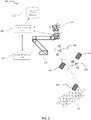
- FIG. 1 a schematic illustration of an exemplary scenario of generating a dataset mapping visual features of an object, according to some examples of the present invention.
- a mechanical device 109 is shown holding an object 105.
- the mechanical device may be a robot, a robotic machine, a conveyer or any other mechanical device having at least one degree of freedom in motion in space dimension.
- Object 105 may be a biscuit, a vegetable, a box, a wet wipe, manufactured goods, raw materials, semi-manufactured goods, a packing box, a case, etc.
- the robotic machine 109 may be equipped with a gripper 107 for holding the object.
- Gripper 107 may have various shapes, sizes and designs to be adapted to different objects.
- a gripper may have different number of degrees of freedom, depending on the design complexity, the operational requirements, the shape and characteristics of the objects and the complexity of the tasks assigned to the robotic machine.
- the system includes at least one image sensor 101 and 102.
- the image sensor(s) may be a camera, a depth map sensor and the like.
- the robotic device is set to move the object 105 from one position in space to another position in space, in front of the image sensor 101, 102. This way, images of the object are captured from different distances, angles and aspects.
- Visual signs may be attached to the at least one sensor 103, to the object 106, to the end point of the mechanical device 108 and/or to any object or equipment in the field of view of the sensor 104.
- the visual signs may assist and improve the ability to process images taken by the sensors and to provide improved accuracy in extracting positional information.
- the visual signs may be bar codes, unique color labels, custom printed stickers in different sizes, chessboard stickers, and the like.
- Vision Processing Unit 111 and Object-Learning Vision system 113 are computing systems for processing and analyzing images captured by the image sensors 101 and 102, as is described below. Vision Processing Unit 111 and Object-Learning Vision system 113 may be comprised of software components and hardware elements including, but not limited to, at least one hardware processor, at least one input/output interface, at least one communication interface, memory medium and user interface.
- Robot Processing Unit 110 is a computing system that receives and processes positional data of the robotic machine and communicates the information with the Object-Learning Vision system 113. The Robot Processing Unit 110 may receive instructions from the Object-Learning Vision system 113 to control the robotic machine 109 to move the object 105 from one position to another position.
- Robot Processing Unit 110 may be comprised of software components and hardware components, including at least one processor, communication interface, input/output interfaces and memory medium.
- Objects Database 112 is a storage medium that stores datasets of objects, as will be explained below.
- the Object Database 112 is controlled by the Object-Learning Vision system.
- the datasets stored on the Object Database 112 may be in digital format, flat files or other digital data storage format with a schema that is optimized to store and dynamically be retrieved by the Object-Learning Vision system.
- a virtual three dimensional coordinates system is shown as 114.
- the positional information reported by the Robot Processing Unit 110 may include 3 dimensional location of the end point of the robotic machine using x, y, z coordinates in the coordinates system 114, and rotational information Rx, Ry, Rz of the end point relative to the x, y, z coordinates.
- the rotational information may be the rotational information of the wrist movement of the gripper 107.
- FIG. 2 a schematic illustration of another exemplary scenario of generating a dataset mapping visual features of an object some examples.
- FIG. 2 illustrates another exemplary scenario 200 of generating a dataset mapping visual features of an object, according to some examples of the present invention.
- the image sensor may be a camera, a depth map sensor or the like.
- the mechanical device 205 may be a robot, a robotic machine, or other mechanical device with at least one degree of freedom in motion in space.
- An object under training 207 may be positioned in fixed place or may be placed on a movable mechanism, for example a conveyer 209.
- the robot 205 is set to move the camera 204 from one position in space to another position in space, in a way that the object 207 is kept in the field of view of the camera.
- Visual signs may be attached to the conveyer 210, to the object 206 and/or to any object or equipment in the field of view of the sensor 208.
- the visual signs may assist and improve the ability to process images taken by the sensors and to provide improved accuracy in extracting positional information.
- the visual signs may be bar codes, unique color labels, custom printed stickers in different sizes, chessboard stickers, and the like.
- a virtual three dimensional coordinates system is shown as 212.
- Vision Processing Unit 202 is a computing system for processing and analyzing images captured by the image sensors 204, as is described below.
- Vision Processing Unit 202 may be comprised of software components and hardware elements including, but not limited to, at least one hardware processor, at least one input/output interface, at least one communication interface, memory medium and user interface.
- Robot Processing Unit 201 is a computing system that receives and processes positional data of the robotic machine that holds the image sensor 204, and communicates the information with the Vision Processing Unit 202.
- the Robot Processing Unit 201 may receive instructions from the Vision Processing Unit 202 to control the robotic machine 205 to move the image sensor 204 from one position to another position.
- Robot Processing Unit 201 may be comprised of software components and hardware components, including at least one processor, communication interface, input/output interfaces and storage medium.
- Objects Database 203 is a storage medium that stores datasets of objects, as will be explained below.
- the Object Database 203 may be controlled by the Vision Processing Unit 202.
- the datasets stored on the Object Database 203 may be in digital format, flat files or other digital data storage format with a schema that is optimized to store and dynamically be retrieved by the Vision Processing Unit 202.
- the positional information reported by the Robot Processing Unit 201 may include 3 dimensional location of the end point of the robotic machine using x, y, z coordinates in the coordinates system 212, and rotational information Rx, Ry, Rz of the end point relative to the x, y, z coordinates.
- a conveyer 209 reports its positional data to other mechanical devices processing units such as 201 and/or to the Vision Processing Unit 202 and this information is also stored associated to the rest of the data retrieved for this position and point in time.
- a conveyer 209 may report positional information using encoders. Encoder may be a digital encoder, analog encoder, optical encoder and the like.
- FIG. 3 a flowchart of an exemplary process of generating a dataset mapping visual features of an object some examples.
- the method for generating a dataset mapping visual features of an object is an iterative process.
- Process 300 depicts an exemplary single iteration in the method.
- the multi iteration process is referred herein as a training process that is conducted in order to train an object to the system.
- Scenario 100 is an exemplary setup of a system to conduct process 300.
- Object 105 is held by a mechanical device 107.
- the mechanical device is a robot or a robotic machine.
- the robotic machine is equipped with a gripper 105 adapted to hold the object.
- the gripper may be of different variations, for example - different degrees of freedom, different sizes, different mechanical element, different holding capabilities, adapted to hold objects of different shapes, adapted to hold objects of different weight, adapted to handle objects of different rigidness, and the like.
- the robot is adapted to move the object from one position in space to another position in space according to instruction received from the Robot Processing Unit 110.
- the robot moves the objects in steps.
- the steps size is randomly selected.
- the step size is a predefined step size.
- the step direction is randomly defined.
- the step direction is predefined.
- identifiable signs 108 are attached to the end point of the robot.
- identifiable signs are attached to the object 106.
- images of the object 105 are collected.
- the images are captured by at least one image sensor 102.
- images are captured by additional image sensor 101.
- an image sensor is a camera.
- an image sensor is a depth map sensor.
- the images are collected by Robot assisted Object-Learning Vision system 113.
- the images may be transferred from the image sensor(s) to the Robot assisted Object-Learning system through wired communication channel.
- the images are transferred through wireless communication channel.
- a time stamp of each of the captured images may be transferred to the Robot assisted Object-Learning system and associated to the respective image.
- the Robot Processing Unit 110 collects positional data of the robotic machine.
- the positional data is received from encoders mounted on the robotic machine.
- the encoders may be digital encoders, analog encoders, optical encoders and the like.
- the Robot Processing Unit receives from the robotic machine rotational information of the end point of the robot.
- the rotational information may be relative to the positional information of the robot.
- the positional information may consist of Cartesian coordinates relative to a predefined point in space 114.
- Time information associated with the positional information is collected by the Robot Processing Unit 110.
- the Robot Processing Unit extracts from the positional data a 3D data which may consist of 3 dimensional coordinates x, y, z, and 3 rotational variables Rx, Ry and Rz representing the rotational information in 3 degrees of freedom of the end point around the positional coordinates.
- the end point is a gripper.
- the Vision Processing Unit 111 analyzes the images collected from the image sensors.
- the analysis includes extraction of a set of visual image features of the object 105, as captured by the image sensors.
- the set of features may include contours, center of contours, size of contours, edges, color areas, etc.
- a visual feature is a 2D feature.
- a visual feature is a 3D feature.
- the Robot assisted Object-Learning Vision system may select a group of the extracted features. The selection may be performed based on pre-configuration of the system and/or based on previously learned objects and identification of features that are unique to current scene.
- a user defines criteria for the selection.
- the Robot assisted Object-Learning vision associates the positional information and the rotational information collected by the Robot Processing Unit with the image visual features extracted by the Vision Processing Unit. The association may be conducted based on a match between the time stamp received with the images and the time stamp received with the positional and rotational data.
- data records comprising the positional data, the rotational data and the associated image visual features are stored in Object Database 112.
- a quantified value for each of the image visual features is stored in the respective data record.
- additional information is added manually by a user.
- the additional information is a designation of "good” object.
- the additional information is a designation of "bad" object.
- the Robot assisted Object-Learning vision system 113 may determine when there is a need to perform another iteration, or to terminate the process.
- a decision may be based on a threshold.
- the threshold may be previously configured as number of iterations.
- the threshold may be defined as an area in space that must be scanned. For example, it may be decided that the scanning process should cover a cubic space of 1m ⁇ 1m ⁇ 1m. When this space is covered, the trigger indicates that no more iterations are needed.
- Step 309 is performed when another iteration is needed. In such case, the Robot assisted Object-Learning vision system instructs the mechanical device to move the object to a next position in space.
- the movement is defined as a given unit distance in a given direction (for example, one step of 1mm in x axes).
- the Robot assisted Object-Learning Vision system may be configured to instruct the robot to go through a cubic area by signaling the size in axes X,Y,Z of the space to be scanned. For example, when x reaches limit of this cube in X axis, it may be reinitialized while y in Y axis is incremented 1mm. When y limit is reached in Y axis, both x and y may be reinitialized and z is incremented one step in Z axes.
- Step 309 is conducted, and the robotic machine has moved the object to a next position in space, a next iteration is started from steps 301 and 302.
- step 310 is a post-processing step, conducted by, for example, the Robot assisted Object-learning Vision system on the data records stored in the Objects Database 112.
- the visual features stored in the dataset of the trained object in the Objects Database are analyzed. Each feature is analyzed and considered whether the feature assists in uniquely identifying the particular object newly trained into the system. Those features identified as not relevant are marked as such.
- This analysis is conducted by comparing each feature of the newly trained object with relevant features of previously stored datasets of previously trained objects. The rest of the objects stored in the database. When no feature is found to identify such uniqueness, the process may progressively mark additional features of previously trained objects as relevant. The post-processing process continues in an iterative way until finding unique features in each object. When no combination of features is found to define the newly trained object as unique, the system may report an error. An error may be indicative of ambiguous object.
- the ambiguous object may be an object already existing in the data base, or an object that it may be hard to distinguish it from previously learned objects.
- FIG. 4 a flowchart of an exemplary process of using dataset mapping visual features of an object, according to some examples of the present invention. Reference is also made to FIG. 1 .
- Flowchart 400 depicts a method for a system to identify new objects by using previously trained objects.
- Robot assisted Object-Learning Vision system 113 collects images captured by an image sensor 102.
- the sensor is a camera.
- the sensor is a depth map sensor.
- the captured images depict an object 105 held by a mechanical device 109.
- the mechanical device is a robotic machine.
- the mechanical device is a conveyer.
- the object 105 may be a biscuit, a vegetable, a box, a wet wipe, manufactured goods, raw materials, semi-manufactured goods, a packing box, a case, etc.
- the Vision Processing Unit 111 analyzes the images and extracts visual image features of the object.
- the image features are 2D features.
- the visual features are 3D features.
- the features may be number of contours, contours' sizes, perimeters and areas and the like.
- the extracted features are features that have been previously marked as relevant in step 305 of process 300, in the dataset of trained objects stored in the Objects Database 112.
- the system searches through the Objects Database 112 to identify a record that best matches the features extracted from the currently inspected object. For example, the record corresponding to a previously stored object that has same x, y pixel center and similar diameter, a number of contrast points (for example by using a function like findContrast) within its range, etc.
- the system determines when the match found is statistically significant.
- step 406 the system retrieves from the record of the identified object in the dataset in the Database 112 the 3D positional data, as described in FIG. 1 .
- step 407 the system feeds the information retrieved about the identified object to other software modules or robot control software that may perform given actions and tasks on the particular object found.
- step 405 the decision is that there is no unique match between extracted features and the features of trained objects, the system may repeat steps 401 through 405 in attempt to identify another feature that may be matched to a feature of an object in the data base.
- FIG. 5 a schematic illustration of an exemplary scenario of training a system to an object with human assistance, according to some examples of the present invention.
- a human 509 assists the system in the training process.
- a mechanical device 512 such as, for example a robotic machine or a robot is placed in the working area and needs to be trained to perform tasks related to an object 508.
- a task is to grasp an object from a conveyer 516 and place it in a box 513.
- Visual signs may be attached to the robotic machine 511.
- visual signs are attached to the conveyer 510.
- a visual sign is attached to the object 507.
- the visual signs may be bar codes, unique color labels, custom printed stickers in different sizes, chessboard stickers, and the like.
- the human 509 demonstrates the task of picking an object 508 from the conveyer 516 and placing it in the box 513.
- one or more image sensors 502 and 504 may capture images depicting the demonstration.
- at least one of the image sensors is a camera.
- at least one of the image sensors is depth map sensor.
- images and 3D coordinates of the object are being collected.
- the system uses process 300 described in FIG. 3 to store a dataset for the new object.
- process 400 will be conducted, as described in FIG.
- 3D positional data is collected, such as aligned depth map and RGB frame generated by the depth sensor and digital camera.
- the Vision Processing Unit 506 detects the displacement of the object 508 in space and its relative position with regards to the sensors.
- the Robot assisted Object-Learning Vision system 515 extracts from the positional information of the object the way the human packed the object in the box 513.
- visual signs are placed on the sensors 501and 503 to facilitate the process of identifying the relative position of the sensors, with regards to each other, and of with regards to the identified object.
- the robot 512 is identified by the sensors as well.
- the Vision Processing Unit may transfer to the robot processing unit 514 these positions relative the robot, and coordinates the robots movements so that it may perform the pick and place task of the learned object, and place the object with the same distribution inside the box 513.
- FIG. 6 a schematic illustration of an exemplary scenario of using dataset mapping visual features of an object, according to some examples of the present invention.
- a mechanical device 609 is shown holding an object 605.
- the mechanical device may be a robot, a robotic machine or any other mechanical device having at least one degree of freedom in motion in space dimension.
- Object 605 may be a biscuit, a vegetable, a box, a wet wipe, manufactured goods, raw materials, semi-manufactured goods, a packing box, a case, etc.
- the robotic machine 609 may be equipped with a gripper 607 for holding the object.
- Gripper 607 may have various shapes, sizes and designs to be adapted to grip different objects.
- a gripper may have different number of degrees of freedom, depending on the design complexity, the operational requirements, the shape and characteristics of the objects and the complexity of the tasks assigned to the robotic machine.
- the system includes at least one image sensor 602 and 604.
- the image sensor(s) may be a camera, a depth map sensor and the like.
- the robotic device is set to move the object 605 and to manipulate it according to the tasks assigned to the robot, in front of the image sensor 602, 604.
- Visual signs may be attached to the sensors 601 and 603, to the end point or the gripper of the mechanical device 606 and/or to any object or equipment 608 in the field of view of the sensors 602 and 604.
- a conveyer 615 is provided as part of the operational environment, to transfer the object and other objects during operation.
- visual sign 608 is placed attached to the conveyer 615.
- the visual signs 601, 603, 606 and 608 facilitate the identification and conversion of coordinates of the object relative to sensors, relative to box and/or relative to the robot.
- the operational environment may be a manufacturing line, a packing line where objects like object 605 need to be placed in boxes like 612, an object selection line and the like.
- the visual signs may assist and improve the ability to process images taken by the sensors and to provide improved accuracy in extracting positional information.
- the visual signs may be bar codes, unique color labels, custom printed stickers in different sizes, chessboard stickers, and the like.
- Vision Processing Unit 611 and Object-Learning Vision system 614 are computing systems for processing and analyzing images captured by the image sensors 602 and 604.
- Vision Processing Unit 611 and Object-Learning Vision system 614 may be comprised of software components and hardware elements including, but not limited to, at least one hardware processor, at least one input/output interface, at least one communication interface, storage medium and user interface.
- Robot Processing Unit 610 may be a computing system that receives and processes positional data of the robotic machine and communicates the information with the Object-Learning Vision system 614.
- Robot Processing Unit 610 may be comprised of software components and hardware components, including at least one processor, communication interface, input/output interfaces and memory medium.
- Objects Database 613 is a storage medium that stores datasets of objects, as explained above.
- the Object Database 613 is controlled by the Object-Learning Vision system.
- the datasets stored on the Object Database 613 may be in digital format, flat files or other digital data storage format with a schema that is optimized to store and dynamically be retrieved by the Object-Learning Vision system.
- objects may be moving on conveyer 615.
- the Robot Processing Unit 610 communicates with the Vision Processing Unit 611 which performs the process 400 described in FIG. 4 using Objects Database 613.
- FIG. 7 is a schematic illustration of an exemplary scenario of generating a dataset mapping visual features of an object in a quality control process, according to some examples of the present invention.
- scenario 700 a set of objects 705 that are considered as complying the specifications of such objects are presented in front of the system's sensors 702 and 711.
- the object 705 is placed in a fixed position.
- object 705 is placed on a conveyer in a conveyer 712.
- the object is trained to the system using Robot assisted Object-Learning system 711, Vision Processing Unit 709, Objects Database 710 and Processing Unit 708.
- Optionally visual identification signs 701,703 are placed on each of the sensors in the scene in order to allow each of the sensors to detect the relative position of the other sensor.
- Optionally visual sign 704 is attached to the conveyer 712.
- the visual signs may be bar codes, unique color labels, custom printed stickers in different sizes, chessboard stickers, and the like.
- the Processing Unit 708 operates in the same manner as the Robot Processing Unit 110 of scenario 100. Processing Unit 708 controls the conveyer 712.
- a conveyer encoder position is used and reported by the Processing Unit.
- no positional data is used and no mechanical device is present.
- no positional information is provided to the Vision Processing Unit 709.
- the system detects object 705 without positional information.
- additional features are manually entered to the database 710 associated with the object 705.
- the additional features are entered by an operator.
- additional features are classification of the object.
- the classification assigns a designation of a value of "Good Object”.
- additional features are manually entered to the database 710 associated with the object 706.
- the additional features are entered by an operator.
- the additional features are a designation of a classification of the object, for example a value of "Bad Object".
- the above description demonstrates a process of executing the training process once on "good objects", and once on “bad objects” such that the system detects unique 2D and/or 3D features that uniquely identify objects that comply with specs from objects that do not comply with specs.
- the additional human feedback described above as manual entry of features allows the system to identify false positives/false negatives and improves the identification and classification mechanism by the Vision processing unit 709.
- Those features that uniquely identify "good” objects from "bad” objects are stored in the objects database and are retrieved later to identify and classify objects inspected according to process 400 described in FIG. 4 .
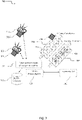
- FIG. 8 is a schematic illustration of an exemplary scenario of generating a dataset mapping visual features of an object assisted by co-planar circular stickers, according to some examples of the present invention.
- the training process is similar to scenario 100, and includes a mechanical device 802 like a robot, controlled by a Robot Processing Unit 801, an image sensor, like a digital camera 804, and Robot assisted Object-Learning Vision system 805, Vision Processing Unit 807 and Objects Database 806, similar to process 100 of FIG. 1 .
- the scenario 800 is assisted by adding one or more circular stickers 808 to the surface of an object 803. This object is held to the end point of the robot 802.
- the stickers may be of a high-contrast color with respect to the background in order to assist image segmentation process.
- the digital camera sends the frame image to the Vision Processing Unit 807.
- the Vision Processing Unit then extracts the pixel coordinates of the center of each sticker, as well as the length in pixels of the minor and major axes of the 2D ellipse corresponding to the each of the circular stickers.
- an image of a circular sticker is taken not exactly from a parallel plane to the plane of the sticker, the circular shape of the sticker appears in the 2D image as an ellipse having minor and major axes.
- each circular sticker has different values associated to it for x, y center coordinates and major and minor axes, measured in pixels.
- the robot reports, by the Robot Processing Unit 801, to the Vision Processing system 807 the x, y, z coordinates of the end-point and the Rx, Ry, Rz rotation of the end point with regards to each axis. These coordinates are associated with the values extracted from the image of the circular stickers for each frame, and stored in the Objects Database 806 for later retrieval.
- composition or method may include additional ingredients and/or steps, but only if the additional ingredients and/or steps do not materially alter the basic and novel characteristics of the claimed composition or method.
- a compound or “at least one compound” may include a plurality of compounds, including mixtures thereof.
Claims (12)
- Verfahren zum Erzeugen eines Datensatzes, der visuelle Merkmale von jedem einer Vielzahl von verschiedenen Objekten (105) mappt, umfassend:
für jedes der Vielzahl verschiedener Objekte (105):Durchführen einer Vielzahl von Iterationen, wobei jede Iteration Folgendes umfasst: Anweisen entweder eines Robotersystems (109), einen Arm, der ein jeweiliges Objekt (105) hält, zu einer nächsten Position aus einer Vielzahl von verschiedenen Positionen vor mindestens einem Sensor zu bewegen, odereiner mechanischen Vorrichtung, die mit mindestens einem Sensor ausgestattet ist, um sich zu einer nächsten Position aus einer Vielzahl von verschiedenen Positionen zu bewegen, sodass das Objekt in dem Sichtfeld des mindestens einen Sensors gehalten wird, um aus verschiedenen Winkeln, Entfernungen und Aspekten erfasst zu werden;Erfassen mindestens eines Bilds von dem mindestens einen Sensor, das das jeweilige Objekt (105) in einer Perspektive der nächsten Position darstellt,Empfangen von Positionsinformationen des Arms oder der mechanischen Vorrichtung in der jeweiligen nächsten Position,Analysieren des mindestens einen Bilds, um mindestens ein visuelles Merkmal des Objekts (105) zu extrahieren, wie es in dem mindestens einen Bild in der jeweiligen nächsten Position dargestellt ist,Assoziieren des mindestens einen visuellen Merkmals mit der Positionsinformation, um eine Assoziation zwischen dem mindestens einen visuellen Merkmal und den Positionsinformationen zu schaffen, undSpeichern, in einem Mapping-Datensatz, der in einer Objektdatenbank (112) gespeichert ist, mindestens eines Datensatzes, umfassend das mindestens eine visuelle Merkmal mit den Positionsinformationen;Entscheiden, ob weitere Iterationen erforderlich sind, und wenn eine Entscheidung getroffen wird, dass keine weiteren Iterationen erforderlich sind, dann Durchführen eines Nachbearbeitungsprozesses, wobei der Nachbearbeitungsprozess Folgendes umfasst:Analysieren der visuellen Merkmale, die in dem Mapping-Datensatz des Objekts gespeichert sind, sodass jedes visuelle Merkmal analysiert und in Betracht gezogen wird, ob das Merkmal das Objekt eindeutig identifiziert, indem jedes visuelle Merkmal des Objekts mit relevanten Merkmalen von zuvor gespeicherten Datensätzen von zuvor trainierten Objekten verglichen wird, wobei visuelle Merkmale, die als nicht relevant identifiziert werden, als solche markiert werden, und wobei, wenn kein visuelles Merkmal gefunden wird, um eine solche Einzigartigkeit zu identifizieren, sodass die visuellen Merkmale des Objekts mit den relevanten Merkmalen von zuvor gespeicherten Datensätzen von zuvor trainierten Objekten übereinstimmen und in jenen vorherigen Datensätzen definiert wird, dass die relevanten Merkmale ausreichend sind, um jene zuvor trainierten Objekte eindeutig zu identifizieren, Aktivieren anderer visueller Merkmale jener vorherigen Trainingssätze, sodass sie die zuvor trainierten Objekte hinsichtlich des Objekts eindeutig identifizieren können, Fortsetzen des Nachbearbeitungsprozesses auf eine iterative Weise, bis eindeutige visuelle Merkmale in jedem der zuvor trainierten Objekte und dem Objekt gefunden werden, und Ausgeben des Mapping-Datensatzes, um eine Identifizierung und eine Lokalisierung der Vielzahl verschiedener Objekte zu ermöglichen;wobei, wenn keine Kombination von visuellen Merkmalen gefunden wird, um das Objekt als einzigartig zu definieren, ein Fehler gemeldet wird. - Verfahren nach Anspruch 1, wobei das mindestens eine Bild durch mindestens eines von der mindestens einen Kamera (101, 102) und mindestens einen Sensor (101, 102), der ein Tiefenkartenbild erfasst, erfasst wird.
- Verfahren nach Anspruch 1, wobei das mindestens eine visuelle Merkmal ein Mitglied einer Gruppe ist, bestehend aus einem zweidimensionalen, 2D, Bildmerkmal und einem dreidimensionalen, 3D, Bildmerkmal.
- Verfahren nach Anspruch 1, wobei die Anweisung mindestens einen Bewegungsbefehl beinhaltet, der eine Schrittgröße und eine Schrittrichtung beinhaltet, wobei die Schrittgröße und die Schrittrichtung entweder vordefiniert oder zufällig ausgewählt sind.
- Verfahren nach Anspruch 1, wobei das mindestens eine visuelle Merkmal ein Mitglied einer Gruppe ist, bestehend aus Kontur, Konturmitte, Anzahl der Konturen, Rändern, Farbflächen, Größe, Umfang und Fläche.
- Verfahren nach Anspruch 1, wobei das mindestens eine visuelle Merkmal eine Vielzahl von Merkmalen ist, die mindestens die folgenden Merkmale beinhaltet:eine Summe eines Blaukanalwerts aller Pixel innerhalb einer Kontur des Objekts, geteilt durch eine Summe eines Grünkanalwerts und eines Rotkanalwerts aller Pixel in der Kontur des Objekts,eine Summe des Grünkanalwerts aller Pixel innerhalb der Kontur des Objekts, geteilt durch eine Summe des Blaukanalwerts und des Rotkanalwerts aller Pixel in der Kontur des Objekts,eine Summe des Rotkanalwerts aller Pixel innerhalb der Kontur des Objekts, geteilt durch eine Summe des Blaukanalwerts und des Grünkanalwerts aller Pixel in der Kontur des Objekts, einen Umfang des Objekts undeine Reihe von Ecken des Objekts;wobei, wenn das Objekt eine sphärische oder elliptische Form aufweist, die Vielzahl von Merkmalen ferner einen Faktor beinhaltet, der durch eine Division einer Dimension der Hauptachse der sphärischen oder elliptischen Form durch eine Dimension einer Nebenachse der sphärischen oder elliptischen Form berechnet wird.
- Verfahren nach Anspruch 6, wobei der Blaukanalwert ein modifizierter Blaukanalwert ist, der gemäß einer gewichteten Berechnung des Blaukanalwerts, des Grünkanalwerts und des Rotkanalwerts berechnet wird, wobei der Grünkanalwert ein modifizierter Grünkanalwert ist, der gemäß einer gewichteten Berechnung des Blaukanalwerts, des Grünkanalwerts und des Rotkanalwerts berechnet wird, und
wobei der Rotkanalwert ein modifizierter Rotkanalwert ist, der gemäß einer gewichteten Berechnung des Blaukanalwerts, des Grünkanalwerts und des Rotkanalwerts berechnet wird. - Verfahren nach Anspruch 7, wobei die Vielzahl von Merkmalen ferner die folgenden Merkmale beinhaltet:eine Anzeige, wenn eine Summe eines modifizierten Blaukanalwerts aller Pixel innerhalb der Kontur des Objekts, geteilt durch eine Summe des modifizierten Grünkanalwerts und des modifizierten Rotkanalwerts aller Pixel in der Kontur des Objekts, größer oder kleiner als ein erster vordefinierter Schwellenwert, geteilt durch eine Gesamtzahl von Pixeln in der Kontur des Objekts ist, eine Anzeige, wenn eine Summe eines modifizierten Rotkanalwerts aller Pixel innerhalb der Kontur des Objekts, geteilt durch eine Summe des modifizierten Grünkanalwerts und des modifizierten Blaukanalwerts aller Pixel in der Kontur des Objekts, größer oder kleiner als ein zweiter vordefinierter Schwellenwert, geteilt durch die Gesamtzahl von Pixeln in der Kontur des Objekts ist, undeine Anzeige, wenn eine Summe eines modifizierten Grünkanalwerts aller Pixel innerhalb der Kontur des Objekts, geteilt durch eine Summe des modifizierten Rotkanalwerts und des modifizierten Blaukanalwerts aller Pixel in der Kontur des Objekts, größer als oder kleiner wie ein dritter vordefinierter Schwellenwert, geteilt durch die Gesamtzahl von Pixeln in der Kontur des Objekts ist.
- Verfahren nach Anspruch 1, wobei das Speichern mindestens eines von einem Speichern eines quantifizierten Werts des mindestens einen visuellen Merkmals in dem Kartierungsdatensatz und einem Speichern mindestens eines Merkmals des Objekts, das von einem Benutzer bereitgestellt wird, beinhaltet.
- Verfahren nach Anspruch 1, wobei das Analysieren ein Identifizieren mindestens eines identifizierbaren Zeichens (106, 108), das an mindestens einem von dem Objekt (105) und einem Greiferteil (107) des Robotersystems (109) angebracht ist.
- Verfahren nach Anspruch 1, wobei das Robotersystem ein Förderer (209) ist, der ein Förderband zum Bewegen des Objekts aufweist.
- Verfahren nach Anspruch 1, wobei das Analysieren ein Identifizieren in dem mindestens einen Bild eines identifizierbaren Zeichens (206) beinhaltet, das an dem Objekt (207) angebracht ist.
Applications Claiming Priority (2)
| Application Number | Priority Date | Filing Date | Title |
|---|---|---|---|
| US201662338558P | 2016-05-19 | 2016-05-19 | |
| PCT/IL2017/050564 WO2017199261A1 (en) | 2016-05-19 | 2017-05-18 | Robot assisted object learning vision system |
Publications (3)
| Publication Number | Publication Date |
|---|---|
| EP3458919A1 EP3458919A1 (de) | 2019-03-27 |
| EP3458919A4 EP3458919A4 (de) | 2020-01-22 |
| EP3458919B1 true EP3458919B1 (de) | 2022-08-24 |
Family
ID=60324862
Family Applications (1)
| Application Number | Title | Priority Date | Filing Date |
|---|---|---|---|
| EP17798895.3A Active EP3458919B1 (de) | 2016-05-19 | 2017-05-18 | Robotergestütztes objektlernendes visionssystem |
Country Status (4)
| Country | Link |
|---|---|
| US (1) | US10974394B2 (de) |
| EP (1) | EP3458919B1 (de) |
| JP (1) | JP2019518297A (de) |
| WO (1) | WO2017199261A1 (de) |
Families Citing this family (31)
| Publication number | Priority date | Publication date | Assignee | Title |
|---|---|---|---|---|
| US10179407B2 (en) * | 2014-11-16 | 2019-01-15 | Robologics Ltd. | Dynamic multi-sensor and multi-robot interface system |
| US10974394B2 (en) | 2016-05-19 | 2021-04-13 | Deep Learning Robotics Ltd. | Robot assisted object learning vision system |
| ES2927177T3 (es) | 2017-02-07 | 2022-11-03 | Veo Robotics Inc | Monitorización de la seguridad del espacio de trabajo y control de equipos |
| US11541543B2 (en) | 2017-02-07 | 2023-01-03 | Veo Robotics, Inc. | Dynamic, interactive signaling of safety-related conditions in a monitored environment |
| US11820025B2 (en) | 2017-02-07 | 2023-11-21 | Veo Robotics, Inc. | Safe motion planning for machinery operation |
| US11518051B2 (en) | 2017-02-07 | 2022-12-06 | Veo Robotics, Inc. | Dynamic, interactive signaling of safety-related conditions in a monitored environment |
| JP2018169660A (ja) * | 2017-03-29 | 2018-11-01 | セイコーエプソン株式会社 | オブジェクト姿勢検出装置、制御装置、ロボットおよびロボットシステム |
| JP6795471B2 (ja) * | 2017-08-25 | 2020-12-02 | ファナック株式会社 | ロボットシステム |
| DE102017219407A1 (de) * | 2017-10-27 | 2019-05-02 | Robert Bosch Gmbh | Erfassungsvorrichtung |
| JP2019084609A (ja) * | 2017-11-06 | 2019-06-06 | セイコーエプソン株式会社 | ロボット制御装置、ロボットおよびロボットシステム |
| US10572775B2 (en) | 2017-12-05 | 2020-02-25 | X Development Llc | Learning and applying empirical knowledge of environments by robots |
| WO2019153245A1 (en) * | 2018-02-09 | 2019-08-15 | Baidu.Com Times Technology (Beijing) Co., Ltd. | Systems and methods for deep localization and segmentation with 3d semantic map |
| US20190314995A1 (en) * | 2018-04-12 | 2019-10-17 | Aeolus Robotics Corporation Limited | Robot and method for controlling the same |
| WO2019234814A1 (ja) * | 2018-06-05 | 2019-12-12 | 株式会社日立製作所 | カメラ位置姿勢校正装置、カメラ位置姿勢校正方法並びにロボット |
| CN108772824A (zh) * | 2018-06-06 | 2018-11-09 | 深圳市恒晨电器有限公司 | 一种螺丝机械手示教对位方法 |
| US11292133B2 (en) * | 2018-09-28 | 2022-04-05 | Intel Corporation | Methods and apparatus to train interdependent autonomous machines |
| US11312012B2 (en) * | 2019-01-01 | 2022-04-26 | Giant Ai, Inc. | Software compensated robotics |
| US11185978B2 (en) * | 2019-01-08 | 2021-11-30 | Honda Motor Co., Ltd. | Depth perception modeling for grasping objects |
| US10977480B2 (en) * | 2019-03-27 | 2021-04-13 | Mitsubishi Electric Research Laboratories, Inc. | Detection, tracking and 3D modeling of objects with sparse RGB-D SLAM and interactive perception |
| JP7260402B2 (ja) * | 2019-05-31 | 2023-04-18 | ファナック株式会社 | ケーブルの状態を学習する機械学習装置、ロボットシステム、及び機械学習方法 |
| US11037329B2 (en) * | 2019-06-03 | 2021-06-15 | Google Llc | Encoding positional coordinates based on multiple channel color values |
| WO2021030322A1 (en) * | 2019-08-12 | 2021-02-18 | Lm3 Technologies, Inc. | System and method of object detection using ai deep learning models |
| US11839986B2 (en) * | 2019-10-25 | 2023-12-12 | Ocado Innovation Limited | Systems and methods for active perception and coordination between robotic vision systems and manipulators |
| CN111145257B (zh) * | 2019-12-27 | 2024-01-05 | 深圳市越疆科技有限公司 | 物品抓取方法、系统及物品抓取机器人 |
| US11937019B2 (en) | 2021-06-07 | 2024-03-19 | Elementary Robotics, Inc. | Intelligent quality assurance and inspection device having multiple camera modules |
| US11875528B2 (en) * | 2021-05-25 | 2024-01-16 | Fanuc Corporation | Object bin picking with rotation compensation |
| US11605159B1 (en) | 2021-11-03 | 2023-03-14 | Elementary Robotics, Inc. | Computationally efficient quality assurance inspection processes using machine learning |
| US11675345B2 (en) | 2021-11-10 | 2023-06-13 | Elementary Robotics, Inc. | Cloud-based multi-camera quality assurance architecture |
| CN114228950A (zh) * | 2021-11-26 | 2022-03-25 | 江苏科技大学 | 一种基于OpenCV与深度学习的水面物体打捞方法及打捞船 |
| US11605216B1 (en) | 2022-02-10 | 2023-03-14 | Elementary Robotics, Inc. | Intelligent automated image clustering for quality assurance |
| KR20240031731A (ko) | 2022-09-01 | 2024-03-08 | 삼성전자주식회사 | 천장 저장 시스템 및 그 제어 방법 |
Family Cites Families (11)
| Publication number | Priority date | Publication date | Assignee | Title |
|---|---|---|---|---|
| JPH06106490A (ja) * | 1992-09-29 | 1994-04-19 | Fujitsu Ltd | 制御装置 |
| US7957583B2 (en) * | 2007-08-02 | 2011-06-07 | Roboticvisiontech Llc | System and method of three-dimensional pose estimation |
| US8923602B2 (en) | 2008-07-22 | 2014-12-30 | Comau, Inc. | Automated guidance and recognition system and method of the same |
| KR20120027253A (ko) | 2009-04-23 | 2012-03-21 | 코닌클리케 필립스 일렉트로닉스 엔.브이. | 물체-학습 로봇 및 방법 |
| US9124873B2 (en) * | 2010-12-08 | 2015-09-01 | Cognex Corporation | System and method for finding correspondence between cameras in a three-dimensional vision system |
| US9295375B2 (en) * | 2012-09-27 | 2016-03-29 | Hrayr Karnig Shahinian | Programmable spectral source and design tool for 3D imaging using complementary bandpass filters |
| US20130343640A1 (en) * | 2012-06-21 | 2013-12-26 | Rethink Robotics, Inc. | Vision-guided robots and methods of training them |
| JP2015145050A (ja) * | 2014-02-04 | 2015-08-13 | セイコーエプソン株式会社 | ロボットシステム、ロボット制御装置、ロボット制御方法およびロボット制御プログラム |
| JP6472621B2 (ja) * | 2014-08-12 | 2019-02-20 | 株式会社Screenホールディングス | 分類器構築方法、画像分類方法および画像分類装置 |
| US9561587B2 (en) * | 2014-12-16 | 2017-02-07 | Amazon Technologies, Inc. | Robotic grasping of items in inventory system |
| US10974394B2 (en) | 2016-05-19 | 2021-04-13 | Deep Learning Robotics Ltd. | Robot assisted object learning vision system |
-
2017
- 2017-05-18 US US16/302,680 patent/US10974394B2/en active Active
- 2017-05-18 EP EP17798895.3A patent/EP3458919B1/de active Active
- 2017-05-18 JP JP2019513505A patent/JP2019518297A/ja active Pending
- 2017-05-18 WO PCT/IL2017/050564 patent/WO2017199261A1/en unknown
Also Published As
| Publication number | Publication date |
|---|---|
| EP3458919A1 (de) | 2019-03-27 |
| US10974394B2 (en) | 2021-04-13 |
| US20190126487A1 (en) | 2019-05-02 |
| WO2017199261A1 (en) | 2017-11-23 |
| JP2019518297A (ja) | 2019-06-27 |
| EP3458919A4 (de) | 2020-01-22 |
Similar Documents
| Publication | Publication Date | Title |
|---|---|---|
| EP3458919B1 (de) | Robotergestütztes objektlernendes visionssystem | |
| DE102019130046B4 (de) | Robotersytem mit verbessertem Abtastmechanismus | |
| US11317681B2 (en) | Automated identification of shoe parts | |
| CN110084243B (zh) | 一种基于二维码和单目相机的档案识别与定位方法 | |
| US20230041378A1 (en) | Systems and methods for object detection | |
| KR20180014676A (ko) | 비전 시스템에서 3d 정렬 알고리즘의 자동 선택을 위한 시스템 및 방법 | |
| Natarajan et al. | Robust stereo-vision based 3D modelling of real-world objects for assistive robotic applications | |
| Zannatha et al. | Monocular visual self-localization for humanoid soccer robots | |
| Lin et al. | Vision based object grasping of industrial manipulator | |
| Martinez et al. | Automated 3D vision guided bin picking process for randomly located industrial parts | |
| Fan et al. | An automatic robot unstacking system based on binocular stereo vision | |
| Takacs et al. | Control of Robotic Arm with Visual System | |
| Sanchez-Lopez et al. | A real-time 3D pose based visual servoing implementation for an autonomous mobile robot manipulator | |
| Wolnitza et al. | 3D object reconstruction and 6D-pose estimation from 2D shape for robotic grasping of objects | |
| US11436753B2 (en) | Machine vision-based method and system to facilitate the unloading of a pile of cartons in a carton handling system | |
| CA3204014A1 (en) | Machine vision-based method and system to facilitate the unloading of a pile of cartons in a carton handling system | |
| Grigorescu et al. | Robust feature extraction for 3D reconstruction of boundary segmented objects in a robotic library scenario | |
| Sharan et al. | Automating the process of work-piece recognition and location for a pick-and-place robot in a SFMS | |
| Zwierzchowski | Indsustrial robot vison system for moving spherical elements | |
| Pop et al. | Colored object detection algorithm for visual-servoing application | |
| Yermagambet | MACHINE VISION IN ROBOTIC SYSTEMS | |
| Kornuta et al. | Utilization of textured stereovision for registration of 3D models of objects | |
| Reyes et al. | Location and classification of moving fruits in real time with a single color camera | |
| Henderson et al. | Creating a New Dataset for Efficient Transfer Learning for 6D Pose Estimation | |
| Theoharatos et al. | Vision-based guidance of a robotic arm for object handling operations—The white'R vision framework |
Legal Events
| Date | Code | Title | Description |
|---|---|---|---|
| STAA | Information on the status of an ep patent application or granted ep patent |
Free format text: STATUS: THE INTERNATIONAL PUBLICATION HAS BEEN MADE |
|
| PUAI | Public reference made under article 153(3) epc to a published international application that has entered the european phase |
Free format text: ORIGINAL CODE: 0009012 |
|
| STAA | Information on the status of an ep patent application or granted ep patent |
Free format text: STATUS: REQUEST FOR EXAMINATION WAS MADE |
|
| 17P | Request for examination filed |
Effective date: 20181211 |
|
| AK | Designated contracting states |
Kind code of ref document: A1 Designated state(s): AL AT BE BG CH CY CZ DE DK EE ES FI FR GB GR HR HU IE IS IT LI LT LU LV MC MK MT NL NO PL PT RO RS SE SI SK SM TR |
|
| AX | Request for extension of the european patent |
Extension state: BA ME |
|
| DAV | Request for validation of the european patent (deleted) | ||
| DAX | Request for extension of the european patent (deleted) | ||
| A4 | Supplementary search report drawn up and despatched |
Effective date: 20191220 |
|
| RIC1 | Information provided on ipc code assigned before grant |
Ipc: B25J 9/00 20060101ALI20191216BHEP Ipc: G06K 9/00 20060101ALI20191216BHEP Ipc: G05B 15/00 20060101AFI20191216BHEP Ipc: G05B 19/00 20060101ALI20191216BHEP |
|
| STAA | Information on the status of an ep patent application or granted ep patent |
Free format text: STATUS: EXAMINATION IS IN PROGRESS |
|
| STAA | Information on the status of an ep patent application or granted ep patent |
Free format text: STATUS: EXAMINATION IS IN PROGRESS |
|
| 17Q | First examination report despatched |
Effective date: 20201021 |
|
| STAA | Information on the status of an ep patent application or granted ep patent |
Free format text: STATUS: EXAMINATION IS IN PROGRESS |
|
| RIC1 | Information provided on ipc code assigned before grant |
Ipc: G06T 1/00 20060101ALI20220202BHEP Ipc: G05B 19/00 20060101ALI20220202BHEP Ipc: B25J 9/00 20060101ALI20220202BHEP Ipc: G06K 9/00 20060101ALI20220202BHEP Ipc: G05B 15/00 20060101AFI20220202BHEP |
|
| GRAP | Despatch of communication of intention to grant a patent |
Free format text: ORIGINAL CODE: EPIDOSNIGR1 |
|
| STAA | Information on the status of an ep patent application or granted ep patent |
Free format text: STATUS: GRANT OF PATENT IS INTENDED |
|
| INTG | Intention to grant announced |
Effective date: 20220317 |
|
| GRAS | Grant fee paid |
Free format text: ORIGINAL CODE: EPIDOSNIGR3 |
|
| GRAA | (expected) grant |
Free format text: ORIGINAL CODE: 0009210 |
|
| STAA | Information on the status of an ep patent application or granted ep patent |
Free format text: STATUS: THE PATENT HAS BEEN GRANTED |
|
| AK | Designated contracting states |
Kind code of ref document: B1 Designated state(s): AL AT BE BG CH CY CZ DE DK EE ES FI FR GB GR HR HU IE IS IT LI LT LU LV MC MK MT NL NO PL PT RO RS SE SI SK SM TR |
|
| REG | Reference to a national code |
Ref country code: CH Ref legal event code: EP |
|
| REG | Reference to a national code |
Ref country code: IE Ref legal event code: FG4D |
|
| REG | Reference to a national code |
Ref country code: AT Ref legal event code: REF Ref document number: 1514069 Country of ref document: AT Kind code of ref document: T Effective date: 20220915 Ref country code: DE Ref legal event code: R096 Ref document number: 602017061037 Country of ref document: DE |
|
| REG | Reference to a national code |
Ref country code: LT Ref legal event code: MG9D |
|
| REG | Reference to a national code |
Ref country code: NL Ref legal event code: MP Effective date: 20220824 |
|
| PG25 | Lapsed in a contracting state [announced via postgrant information from national office to epo] |
Ref country code: SE Free format text: LAPSE BECAUSE OF FAILURE TO SUBMIT A TRANSLATION OF THE DESCRIPTION OR TO PAY THE FEE WITHIN THE PRESCRIBED TIME-LIMIT Effective date: 20220824 Ref country code: RS Free format text: LAPSE BECAUSE OF FAILURE TO SUBMIT A TRANSLATION OF THE DESCRIPTION OR TO PAY THE FEE WITHIN THE PRESCRIBED TIME-LIMIT Effective date: 20220824 Ref country code: PT Free format text: LAPSE BECAUSE OF FAILURE TO SUBMIT A TRANSLATION OF THE DESCRIPTION OR TO PAY THE FEE WITHIN THE PRESCRIBED TIME-LIMIT Effective date: 20221226 Ref country code: NO Free format text: LAPSE BECAUSE OF FAILURE TO SUBMIT A TRANSLATION OF THE DESCRIPTION OR TO PAY THE FEE WITHIN THE PRESCRIBED TIME-LIMIT Effective date: 20221124 Ref country code: NL Free format text: LAPSE BECAUSE OF FAILURE TO SUBMIT A TRANSLATION OF THE DESCRIPTION OR TO PAY THE FEE WITHIN THE PRESCRIBED TIME-LIMIT Effective date: 20220824 Ref country code: LV Free format text: LAPSE BECAUSE OF FAILURE TO SUBMIT A TRANSLATION OF THE DESCRIPTION OR TO PAY THE FEE WITHIN THE PRESCRIBED TIME-LIMIT Effective date: 20220824 Ref country code: LT Free format text: LAPSE BECAUSE OF FAILURE TO SUBMIT A TRANSLATION OF THE DESCRIPTION OR TO PAY THE FEE WITHIN THE PRESCRIBED TIME-LIMIT Effective date: 20220824 Ref country code: FI Free format text: LAPSE BECAUSE OF FAILURE TO SUBMIT A TRANSLATION OF THE DESCRIPTION OR TO PAY THE FEE WITHIN THE PRESCRIBED TIME-LIMIT Effective date: 20220824 |
|
| REG | Reference to a national code |
Ref country code: AT Ref legal event code: MK05 Ref document number: 1514069 Country of ref document: AT Kind code of ref document: T Effective date: 20220824 |
|
| PG25 | Lapsed in a contracting state [announced via postgrant information from national office to epo] |
Ref country code: PL Free format text: LAPSE BECAUSE OF FAILURE TO SUBMIT A TRANSLATION OF THE DESCRIPTION OR TO PAY THE FEE WITHIN THE PRESCRIBED TIME-LIMIT Effective date: 20220824 Ref country code: IS Free format text: LAPSE BECAUSE OF FAILURE TO SUBMIT A TRANSLATION OF THE DESCRIPTION OR TO PAY THE FEE WITHIN THE PRESCRIBED TIME-LIMIT Effective date: 20221224 Ref country code: HR Free format text: LAPSE BECAUSE OF FAILURE TO SUBMIT A TRANSLATION OF THE DESCRIPTION OR TO PAY THE FEE WITHIN THE PRESCRIBED TIME-LIMIT Effective date: 20220824 Ref country code: GR Free format text: LAPSE BECAUSE OF FAILURE TO SUBMIT A TRANSLATION OF THE DESCRIPTION OR TO PAY THE FEE WITHIN THE PRESCRIBED TIME-LIMIT Effective date: 20221125 |
|
| PG25 | Lapsed in a contracting state [announced via postgrant information from national office to epo] |
Ref country code: SM Free format text: LAPSE BECAUSE OF FAILURE TO SUBMIT A TRANSLATION OF THE DESCRIPTION OR TO PAY THE FEE WITHIN THE PRESCRIBED TIME-LIMIT Effective date: 20220824 Ref country code: RO Free format text: LAPSE BECAUSE OF FAILURE TO SUBMIT A TRANSLATION OF THE DESCRIPTION OR TO PAY THE FEE WITHIN THE PRESCRIBED TIME-LIMIT Effective date: 20220824 Ref country code: ES Free format text: LAPSE BECAUSE OF FAILURE TO SUBMIT A TRANSLATION OF THE DESCRIPTION OR TO PAY THE FEE WITHIN THE PRESCRIBED TIME-LIMIT Effective date: 20220824 Ref country code: DK Free format text: LAPSE BECAUSE OF FAILURE TO SUBMIT A TRANSLATION OF THE DESCRIPTION OR TO PAY THE FEE WITHIN THE PRESCRIBED TIME-LIMIT Effective date: 20220824 Ref country code: CZ Free format text: LAPSE BECAUSE OF FAILURE TO SUBMIT A TRANSLATION OF THE DESCRIPTION OR TO PAY THE FEE WITHIN THE PRESCRIBED TIME-LIMIT Effective date: 20220824 Ref country code: AT Free format text: LAPSE BECAUSE OF FAILURE TO SUBMIT A TRANSLATION OF THE DESCRIPTION OR TO PAY THE FEE WITHIN THE PRESCRIBED TIME-LIMIT Effective date: 20220824 |
|
| REG | Reference to a national code |
Ref country code: DE Ref legal event code: R097 Ref document number: 602017061037 Country of ref document: DE |
|
| PG25 | Lapsed in a contracting state [announced via postgrant information from national office to epo] |
Ref country code: SK Free format text: LAPSE BECAUSE OF FAILURE TO SUBMIT A TRANSLATION OF THE DESCRIPTION OR TO PAY THE FEE WITHIN THE PRESCRIBED TIME-LIMIT Effective date: 20220824 Ref country code: EE Free format text: LAPSE BECAUSE OF FAILURE TO SUBMIT A TRANSLATION OF THE DESCRIPTION OR TO PAY THE FEE WITHIN THE PRESCRIBED TIME-LIMIT Effective date: 20220824 |
|
| PG25 | Lapsed in a contracting state [announced via postgrant information from national office to epo] |
Ref country code: AL Free format text: LAPSE BECAUSE OF FAILURE TO SUBMIT A TRANSLATION OF THE DESCRIPTION OR TO PAY THE FEE WITHIN THE PRESCRIBED TIME-LIMIT Effective date: 20220824 |
|
| PLBE | No opposition filed within time limit |
Free format text: ORIGINAL CODE: 0009261 |
|
| STAA | Information on the status of an ep patent application or granted ep patent |
Free format text: STATUS: NO OPPOSITION FILED WITHIN TIME LIMIT |
|
| PGFP | Annual fee paid to national office [announced via postgrant information from national office to epo] |
Ref country code: IT Payment date: 20230530 Year of fee payment: 7 Ref country code: FR Payment date: 20230530 Year of fee payment: 7 Ref country code: DE Payment date: 20230530 Year of fee payment: 7 Ref country code: CH Payment date: 20230701 Year of fee payment: 7 |
|
| 26N | No opposition filed |
Effective date: 20230525 |
|
| PG25 | Lapsed in a contracting state [announced via postgrant information from national office to epo] |
Ref country code: SI Free format text: LAPSE BECAUSE OF FAILURE TO SUBMIT A TRANSLATION OF THE DESCRIPTION OR TO PAY THE FEE WITHIN THE PRESCRIBED TIME-LIMIT Effective date: 20220824 |
|
| PGFP | Annual fee paid to national office [announced via postgrant information from national office to epo] |
Ref country code: GB Payment date: 20230530 Year of fee payment: 7 |
|
| PG25 | Lapsed in a contracting state [announced via postgrant information from national office to epo] |
Ref country code: MC Free format text: LAPSE BECAUSE OF FAILURE TO SUBMIT A TRANSLATION OF THE DESCRIPTION OR TO PAY THE FEE WITHIN THE PRESCRIBED TIME-LIMIT Effective date: 20220824 |
|
| REG | Reference to a national code |
Ref country code: BE Ref legal event code: MM Effective date: 20230531 |
|
| PG25 | Lapsed in a contracting state [announced via postgrant information from national office to epo] |
Ref country code: MC Free format text: LAPSE BECAUSE OF FAILURE TO SUBMIT A TRANSLATION OF THE DESCRIPTION OR TO PAY THE FEE WITHIN THE PRESCRIBED TIME-LIMIT Effective date: 20220824 Ref country code: LU Free format text: LAPSE BECAUSE OF NON-PAYMENT OF DUE FEES Effective date: 20230518 |
|
| REG | Reference to a national code |
Ref country code: IE Ref legal event code: MM4A |
|
| PG25 | Lapsed in a contracting state [announced via postgrant information from national office to epo] |
Ref country code: IE Free format text: LAPSE BECAUSE OF NON-PAYMENT OF DUE FEES Effective date: 20230518 |