EP3458350B1 - Elektrischer schiffsantrieb und verfahren zum drehen einer antriebswelle eines schiffes - Google Patents
Elektrischer schiffsantrieb und verfahren zum drehen einer antriebswelle eines schiffes Download PDFInfo
- Publication number
- EP3458350B1 EP3458350B1 EP17740006.6A EP17740006A EP3458350B1 EP 3458350 B1 EP3458350 B1 EP 3458350B1 EP 17740006 A EP17740006 A EP 17740006A EP 3458350 B1 EP3458350 B1 EP 3458350B1
- Authority
- EP
- European Patent Office
- Prior art keywords
- drive
- ship
- drive shaft
- pod
- engine
- Prior art date
- Legal status (The legal status is an assumption and is not a legal conclusion. Google has not performed a legal analysis and makes no representation as to the accuracy of the status listed.)
- Active
Links
Images

Classifications
-
- B—PERFORMING OPERATIONS; TRANSPORTING
- B63—SHIPS OR OTHER WATERBORNE VESSELS; RELATED EQUIPMENT
- B63B—SHIPS OR OTHER WATERBORNE VESSELS; EQUIPMENT FOR SHIPPING
- B63B81/00—Repairing or maintaining vessels
Definitions
- the invention relates to an electric ship drive which has a drive machine and a drive shaft, as well as a method for rotating a drive shaft of a ship.
- Ship propulsion systems have a drive shaft, in particular a propeller shaft, and a drive machine.
- the drive machine is, for example, a diesel and / or an electrical machine, such as a synchronous machine or an asynchronous machine. It may be necessary to turn the drive shaft for maintenance work, checks or monitoring on ship propulsion systems. In particular, this rotation is a slow rotation.
- the propeller shaft i. E. the drive shaft
- a round sling has so far been used.
- One or a large number of round slings are placed around a propeller blade or a large number of individual propeller blades, which are then pulled with a crane or vehicles in the dock.
- the drive shaft to which in particular the propeller is attached, can be rotated.
- this procedure can have negative effects on bearings and sealing elements of the propeller shaft, for example, which are caused by the eccentric point of application of the force.
- From the JP 2005 075283 A is known a device for removing a propeller attachment for a ship.
- a motor provides the rotational force for the propeller support, which is inserted between the propellers, so that the hooks provided in the propeller support rods engage the propeller blades.
- hydrostatic ship propeller drive From the GB 1571984 a hydrostatic ship propeller drive is known. This has two housings for motors, which are coupled to the propeller, which can rotate around a common axis.
- the electric pod drive has at least one cavity arranged in the nacelle housing, which is designed such that water can penetrate through at least one housing opening into the at least one cavity for cooling purposes.
- One object of the invention is to facilitate or improve the handling of a ship drive, in particular an electric ship drive.
- the object is achieved in an electric ship propulsion system according to claim 1 or in a method for rotating a drive shaft of a ship in accordance with claim 7.
- Embodiments arise from claims 2 to 6 and 8 to 11, respectively.
- a ship drive in particular an electric ship drive, has a drive machine and a drive shaft. These are especially located in a gondola (POD).
- the drive machine is, for example, a synchronous machine, an asynchronous machine and / or an internal combustion engine such as a diesel.
- the drive shaft is driven either directly or indirectly by the drive machine or the drive machines or is mechanically coupled to it.
- the mechanical coupling takes place, for example, via a flange, a shrink connection, a welded connection, a coupling and / or a gear.
- the drive shaft that is to say the shaft that can be driven by the drive machine, is in particular also the propeller shaft on which the propeller of the ship is seated.
- the drive shaft can be in a POD or in a rudder propeller.
- the drive shaft can also be in the hull of a ship find, the drive shaft is attached to the stern in such a way that it can protrude into the water.
- the drive shaft is mechanically coupled to an auxiliary machine.
- the coupling can take place directly, for example via a pin, or indirectly, for example via a gear.
- the auxiliary machine By using the auxiliary machine, the drive shaft, ie in particular the propeller shaft, and in particular a propeller attached to it, can be rotated. Positioning is also possible. This can be necessary, for example, when assembling, disassembling and / or repairing the propeller.
- the auxiliary machine is located on the POD with the POD case open.
- the POD housing is at least partially open during maintenance work in a dry dock, for example.
- maintenance work is carried out on the drive machine, which is located in the POD.
- the auxiliary machine is attached to the housing of the POD, the POD housing has a housing opening and the auxiliary machine is mechanically coupled to the drive shaft through the housing opening.
- a chain drive or a belt drive is provided for mechanically coupling the auxiliary machine to the drive shaft.
- the chain drive or the belt drive enables simple and / or quick assembly and disassembly of the auxiliary machine.
- a removable auxiliary machine is particularly advantageous for POD drives, since it does not have to be present when the POD is in operation and can be installed in the dock, for example.
- the auxiliary machine with the chain or belt drive represents a turning device, also a turning device, for the drive shaft.
- auxiliary drives there is not just one but a multiplicity of auxiliary drives, that is to say for example two or three auxiliary drives, which are provided for performing a rotary movement of the drive shaft.
- the auxiliary drives are in particular not intended to generate propulsion for the ship.
- the auxiliary drives are used, for example, in the event of repairs, assembly work, dismantling work and / or testing work.
- the auxiliary drive or drives can also be referred to as a rotary drive, since they can be used to rotate the drive shaft, the propeller shaft, the propeller and / or also a rotor of an electric drive machine.
- the auxiliary drive or the auxiliary drives are not positioned in a motor pod but at least partially outside.
- the nacelle can be made compact when the ship is in operation.
- the auxiliary machine is an electric machine, a hydraulic machine, a pneumatic machine or an internal combustion engine.
- An electrical machine is compact and can easily be operated via an external power supply or internal power supply (the ship's electrical network). With hydraulic or pneumatic auxiliary drives, the handling of electrical current in the area of water can be avoided.
- An internal combustion engine can be used independently, without connections for e.g. Having to provide electricity or compressed air.
- the drive machine in particular a permanently excited synchronous machine, has latching positions.
- the locking positions are due to magnetism.
- the auxiliary machine has a controller for controlling or regulating the auxiliary machine.
- the control is for example Integrated in a power converter to feed the electrical auxiliary machine (eg an asynchronous machine or a synchronous machine).
- the drive shaft can be positioned with the aid of the controller and a position transmitter on the auxiliary machine and / or on the drive machine and / or on the drive shaft.
- the drive machine can be positioned outside of a locking position.
- the drive shaft and / or the propeller and / or the drive machine can be rotated slowly and / or held in a defined position.
- the propeller shaft of POD drives can now be fixed in a targeted manner with a permanently excited (PEM) motor with any desired angle of rotation and also outside the detent positions.
- PEM permanently excited
- a suitable receptacle on the propeller shaft For the connection of the auxiliary machine, for example, there is a suitable receptacle on the propeller shaft.
- This receptacle which can be designed as a chain sprocket or belt pulley, can be located on POD drives with two propellers (twin propellers) on one, the other or on both sides of the propeller shaft.
- the connection of the auxiliary machine can also be located on the drive end (drive side / propeller side), as well as on the non-drive end (operator side / free propeller shaft end) or on both propeller shaft sides.
- the ship drive in particular the electric ship drive, it has a brake for braking the drive shaft.
- the brake can be used to reduce a speed or as a parking brake.
- one or more propeller shaft brakes of the POD drive can be set, or the external turn drive, i.e. the auxiliary machine, can be used.
- the auxiliary machine can be switched off when the brake is active.
- the auxiliary machine can also be used as a brake itself. With a speed setpoint of 0, the auxiliary machine can also serve as a parking brake.
- the brake, or a braking device makes it possible to hold occurring moments at any desired position.
- the ship propulsion system in particular the electric ship propulsion system, there is an external power supply connection for the auxiliary machine.
- the auxiliary machine is a motor that is fed, for example, from the power grid in a shipyard or port. So you don't need to connect the engine to the ship's electrical system.
- the ship's own power supply may not be in operation or not in operation sufficiently. Due to the external power supply, which is not fed by the ship's island grid, the propeller shaft can be turned (turned) using external auxiliary equipment.
- the drive shaft and / or the propeller of a ship can be rotated by means of an auxiliary machine.
- the drive shaft is located, for example, in a ship's hull or in a POD.
- the rotation is rotated by means of the auxiliary machine when the ship is stationary.
- the auxiliary machine is located on the POD with an open POD housing, the auxiliary machine being attached to a housing of the POD, the POD housing having a housing opening and the auxiliary machine being mechanically coupled to the drive shaft through the housing opening.
- the rotation is not used to move the ship, but to move or position the shaft or the propeller mechanically coupled to the shaft.
- the auxiliary machine is, for example, an electrical machine which enables the drive shaft to be positioned at an exact angle by means of a control system and a rotary encoder.
- the ship can be in the water or outside, as is the case, for example, in a dry dock. Positioning is helpful, for example, for maintenance work on the propeller, on the bearings, on the drive machine.
- the drive shaft or a drive machine is prevented from rotating by means of a brake.
- the brake may be required to prevent rotary movement when working on the drive shaft or the propeller.
- the method described can be used in different ways in ship propulsion systems.
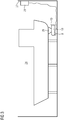
- FIG 1 shows an electric ship drive 1 with a drive machine 3 in a POD 13, the drive machine 3 being mechanically coupled to a propeller 19 via a drive shaft 5.
- the drive machine 3 has a stator 21 and a rotor 22, the rotor 22 being coupled to the drive shaft 5 in a mechanically rigid manner.
- the drive shaft 5 has two sides, which are referred to as the operator-side drive shaft 6 and the drive-side drive shaft 7.
- the drive shaft is supported via a drive-side bearing 17 and an operator-side bearing 18.
- the drive shaft 5 can be rotated via an auxiliary machine 8.
- the auxiliary machine 8 is attached to a housing 14 of the POD 13.
- the auxiliary machine 8 can be mechanically coupled to the drive shaft 5 through this opening 15.
- the coupling takes place, for example, via a transmission.
- a belt drive 10 or, alternatively, a chain drive 9 can be provided for this purpose.
- the transmission has a first diameter 11 of a transmission disk or a chain sprocket on a primary transmission side and a second diameter 12 of a transmission disk or a chain sprocket on a secondary transmission side.
- a transmission can thereby be formed. With different diameters it is possible to develop a transmission ratio.
- the transmission ratio can be adapted to the performance of the auxiliary machine 8 in relation to the inertia of the drive shaft 5.
- an additional transmission can also be provided, which is in the Figure 1 however, is not shown.
- the transmission forms a coupling between the auxiliary machine 8 and the drive shaft 5.
- a controller 20 is provided for controlling and / or regulating the auxiliary machine 8.
- the controller 20 has, for example, a speed control, a position control and / or a torque control. With the position control, for example, a mechanical brake 25 can be replaced with which the position of the drive shaft 5 can be maintained.
- An energy supply connection 26 is used to supply the auxiliary machine 8 and / or the controller 20 with electrical energy.
- This electrical energy can be generated, for example, in the ship belonging to the ship propulsion system, or it can be taken from an electrical supply network in the port or dock. If the electrical energy comes from the ship, you are independent of a shore connection, i.e. independent of an electrical network in a port or a dock. If the electrical energy for the auxiliary machine 8 comes from external sources, that is to say from a network or from an external generator unit with an internal combustion engine, one is independent of the operating state of the ship. This can be advantageous, for example, when the generation of electrical energy on the ship is shut down for maintenance work.
- FIG 2 shows similar to in FIG 1 an electric ship propulsion system 2, with a drive machine 4, which like the drive machine 3 according to FIG 1 is constructed.
- the drive machine 4 is located in the POD 13, which is rotatably attached to a ship's hull 23 via the shaft 29.
- the shaft 29 is hollow and can accommodate electrical supply lines, for example.
- FIG 1 is after FIG 2 the housing opening 15 positioned laterally. This makes handling easier when the distance to the ground is short in a dry dock.
- the auxiliary machine is after FIG 2 not shown, but the pulley or chain sprocket 16 is visible.
- FIG 3 shows a ship 24 in a dry dock 27.
- the auxiliary machine 8 can be supplied with electrical energy via an external energy supply 28. So you are independent of the operating status of the power generators in ship 27.
Landscapes
- Chemical & Material Sciences (AREA)
- Engineering & Computer Science (AREA)
- Combustion & Propulsion (AREA)
- Mechanical Engineering (AREA)
- Ocean & Marine Engineering (AREA)
- Connection Of Motors, Electrical Generators, Mechanical Devices, And The Like (AREA)
Description
- Die Erfindung betrifft einen elektrischen Schiffsantrieb, welcher eine Antriebsmaschine und eine Antriebswelle aufweist, sowie ein Verfahren zum Drehen einer Antriebswelle eines Schiffes.
- Schiffsantriebsanlagen weisen eine Antriebswelle, insbesondere eine Propellerwelle und eine Antriebsmaschine auf. Die Antriebsmaschine ist beispielsweise ein Diesel und/oder eine elektrische Maschine, wie eine Synchronmaschine oder eine Asynchronmaschine. Für Wartungsarbeiten, Kontrollen oder Überwachungen an Schiffsantriebsanlagen kann es erforderlich sein, die Antriebswelle zu drehen. Diese Drehung ist insbesondere eine langsame Drehung.
- In einem Trockendock wird zum Drehen der Propellerwelle, d.h. der Antriebswelle, ohne die Antriebsmaschine selbst zu nutzen bislang eine Rundschlinge verwendet. Eine oder eine Vielzahl von Rundschlingen werden um einen Propellerflügel oder eine Vielzahl einzelner Propellerflügel gelegt, an welchen dann mit einem Kran oder mit Fahrzeugen im Dock gezogen wird. So kann die Antriebswelle, an welcher insbesondere der Propeller befestigt ist, gedreht werden. Diese Vorgehensweise kann allerdings negative Auswirkungen auf beispielsweise Lagerungen und Dichtungselemente der Propellerwelle haben, welche durch den außermittigen Angriffspunkt der Kraft hervorgerufen werden.
- Aus der
JP 2005 075283 A - Aus der
GB 1571984 - Aus der
EP 3 020 625 A1 ist ein elektrischer Gondelantrieb für ein Schiff bekannt. Um eine alternative Kühlung für einen elektrischen Gondelantrieb bereitzustellen, wird vorgeschlagen, dass der elektrische Gondelantrieb zumindest einen im Gondelgehäuse angeordneten Hohlraum aufweist, welcher derart ausgestaltet ist, dass durch zumindest eine Gehäuseöffnung Wasser in den zumindest einen Hohlraum zu Kühlzwecken eindringen kann. - Eine Aufgabe der Erfindung ist es den Umgang mit einem Schiffsantrieb, insbesondere einem elektrischen Schiffsantrieb, zu erleichtern bzw. zu verbessern. Eine Lösung der Aufgabe gelingt bei einem elektrischen Schiffsantrieb nach Anspruch 1 bzw. bei einem Verfahren zum Drehen einer Antriebswelle eines Schiffes nach Anspruch 7. Ausgestaltungen ergeben sich nach den Ansprüchen 2 bis 6 bzw. 8 bis 11.
- Ein Schiffsantrieb, insbesondere ein elektrischer Schiffsantrieb, weist eine Antriebsmaschine und eine Antriebswelle auf. Diese befinden sich insbesondere in einer Gondel (POD). Die Antriebsmaschine ist beispielsweise eine Synchronmaschine, eine Asynchronmaschine und oder eine Verbrennungskraftmaschine, wie ein Diesel. Die Antriebswelle wird von der Antriebsmaschine oder den Antriebsmaschinen entweder direkt oder indirekt angetrieben bzw. ist damit mechanisch gekoppelt. Die mechanische Kopplung erfolgt beispielsweise über einen Flansch, eine Schrumpfverbindung, eine Schweißverbindung, eine Kupplung und/oder ein Getriebe. Die Antriebswelle, also die Welle, welche von der Antriebsmaschine antreibbar ist, ist insbesondere auch die Propellerwelle, auf welcher der Propeller des Schiffes sitzt. Die Antriebswelle kann sich in einem POD oder in einem Ruderpropeller befinden. Die Antriebswelle kann sich auch in einem Rumpf eines Schiffes be finden, wobei die Antriebswelle heckseitig derart angebracht ist, dass diese in das Wasser ragen kann. Die Antriebswelle ist mit einer Hilfsmaschine mechanisch gekoppelt. Die Kopplung kann direkt z.B. über einen Zapfen oder indirekt z.B. über ein Getriebe erfolgen. Durch die Verwendung der Hilfsmaschine kann die Antriebswelle, also insbesondere die Propellerwelle, wie auch insbesondere ein daran befestigter Propeller gedreht werden. Auch eine Positionierung ist möglich. Diese kann beispielsweise bei einer Montage, Demontage und/oder Reparatur des Propellers notwendig sein. Die Hilfsmaschine befindet sich an dem POD mit einem geöffneten POD-Gehäuse. Das POD-Gehäuse ist beispielsweise bei Wartungsarbeiten in einem Trockendock zumindest teilweise geöffnet. Dabei werden z.B. Wartungsarbeiten an der Antriebsmaschine durchgeführt, welche sich im POD befindet. Die Hilfsmaschine ist an dem Gehäuse des PODs befestigt, das POD-Gehäuse weist eine Gehäuseöffnung auf und durch die Gehäuseöffnung ist die Hilfsmaschine mechanisch mit der Antriebswelle gekoppelt.
- In einer Ausgestaltung des Schiffsantriebes, insbesondere des elektrischen Schiffsantriebes, ist zur mechanischen Kopplung der Hilfsmaschine mit der Antriebswelle ein Kettenantrieb oder ein Riemenantrieb vorgesehen. Durch den Kettenantrieb bzw. den Riemenantrieb ist eine einfache und/oder schnelle Montage bzw. Demontage der Hilfsmaschine möglich. Insbesondere für POD-Antriebe ist eine demontierbare Hilfsmaschine von Vorteil, da diese im Betriebszustand des POD nicht vorhandensein muss und z.B. im Dock montiert werden kann. Die Hilfsmaschine mit dem Ketten- oder Riementrieb stellt eine Drehvorrichtung, auch Turnvorrichtung, für die Antriebswelle dar. Die Übertragung der für die Drehbewegung notwendigen Momente von dem/den Drehantrieb(en), also der/den Hilfsmaschine(n) erfolgt also insbesondere mittels eines Ketten- oder Riementriebes, wobei dieser Ketten- oder Riementrieb direkt wirkt oder über ein Getriebe auf die Propellerwelle des POD-Antriebs.
- In einer Ausgestaltung der Erfindung gibt es nicht nur einen sondern eine Vielzahl von Hilfsantrieben, also beispielsweise zwei oder drei Hilfsantriebe, die zur Durchführung einer Drehbewegung der Antriebswelle vorgesehen sind. Die Hilfsantriebe sind dabei insbesondere nicht dafür vorgesehen einen Vortrieb für das Schiff zu erzeugen. Die Hilfsantriebe werden beispielsweise im Reparaturfall, bei Montagearbeiten, bei Demontagearbeiten und/oder bei Prüfarbeiten eingesetzt. Der oder die Hilfsantriebe können auch als Drehantrieb bezeichnet werden, da diese zur Drehung der Antriebswelle, der Propellerwelle, des Propellers und/oder auch eines Rotors einer elektrischen Antriebsmaschine verwendet werden können.
- In einer Ausgestaltung des Schiffsantriebes, insbesondere des elektrischen Schiffsantriebes, ist der Hilfsantrieb bzw. sind die Hilfsantriebe nicht in einer Motorgondel positioniert sondern zumindest teilweise außerhalb. Dadurch lässt sich im Betrieb des Schiffes die Gondel kompakt ausführen.
- In einer Ausgestaltung des Schiffsantriebes, insbesondere des elektrischen Schiffsantriebes, ist die Hilfsmaschine eine elektrische Maschine, eine hydraulische Maschine, eine pneumatische Maschine oder eine Verbrennungskraftmaschine. Eine elektrische Maschine ist kompakt und kann einfach über eine externe Stromversorgung oder interne Stromversorgung (das elektrische Schiffsnetz) betrieben werden. Mit hydraulischen oder pneumatischen Hilfsantrieben lässt sich der Umgang mit elektrischem Strom im Bereich von Wasser vermeiden. Mit einer Verbrennungskraftmaschine kann autark gearbeitet werden, ohne Anschlüsse für z.B. Strom oder Druckluft bereitstellen zu müssen.
- In einer Ausgestaltung des Schiffsantriebes, insbesondere des elektrischen Schiffsantriebes, weist die Antriebsmaschine, insbesondere eine permanenterregte Synchronmaschine, Raststellungen auf. Die Raststellungen rühren vom Magnetismus her. Die Hilfsmaschine weist eine Steuerung zum Steuern oder Regeln der Hilfsmaschine auf. Die Steuerung ist beispielsweise in einem Stromrichter zur Speisung der elektrischen Hilfsmaschine (z.B. eine Asynchronmaschine oder eine Synchronmaschine) integriert. Mit Hilfe der Steuerung und einem Positionsgeber an der Hilfsmaschine und/oder an der Antriebsmaschine und/oder an der Antriebswelle kann eine Positionierung der Antriebswelle erfolgen. So kann beispielsweise die Antriebsmaschine außerhalb einer Raststellung positioniert werden. Mit Hilfe der Hilfsmaschine kann die Antriebswelle und/oder der Propeller und/oder die Antriebsmaschine langsam gedreht werden und/oder an einer definierten Position gehalten werden. So kann nunmehr beispielsweise eine gezielte Festsetzung der Propellerwelle von POD-Antrieben mit einem permanent erregten (PEM-)Motor mit beliebigem Drehwinkel und auch außerhalb der Raststellungen erreicht werden.
- Für den Anschluss der Hilfsmaschine ist beispielsweise eine geeignete Aufnahme an der Propellerwelle vorhanden. Diese Aufnahme, welche als Kettennuss oder Riemenscheibe ausgeprägt sein kann, kann bei POD-Antrieben mit zwei Propellern (Twin-Propeller) an der einen, der anderen oder an beiden Propellerwellenseiten gelegen sein. Bei POD-Antrieben mit nur einem Propeller (Mono-Propeller) kann der Anschluss der Hilfsmaschine ebenso sowohl am drive end (antriebsseitig / propellerseitig), als auch am non-drive end (bedienseitig / freies Propellerwellenende) oder an beiden Propellerwellenseiten gelegen sein.
- In einer Ausgestaltung des Schiffsantriebes, insbesondere des elektrischen Schiffsantriebes, weist dieser eine Bremse zum Bremsen der Antriebswelle auf. Die Bremse kann dabei zur Reduzierung einer Drehzahl oder als Feststellbremse verwendet werden. Zum Festsetzen der Antriebswelle an einer definierten Position können eine oder mehrere Propellerwellenbremsen des POD-Antriebs gesetzt werden, oder aber der externe Turnantrieb, also die Hilfsmaschine, verwendet werden. Die Hilfsmaschine kann bei aktiver Bremse ausgeschaltet werden. Die Hilfsmaschine kann aber auch selbst als Bremse verwendet werden. Bei einem Drehzahlsollwert von 0 kann die Hilfsmaschine auch als Feststellbremse dienen. Die Bremse, bzw. eine Bremseinrichtung, erlaubt es, auftretenden Momente an jeder gewünschten Position zu halten.
- In einer Ausgestaltung des Schiffsantriebes, insbesondere des elektrischen Schiffsantriebes, gibt es einen externen Energieversorgungsanschluss für die Hilfsmaschine. Die Hilfsmaschine ist ein Motor, welcher beispielsweise über das Stromnetz in einer Werft oder einem Hafen gespeist wird. So braucht man den Motor nicht mit dem Bordnetz des Schiffes zu verbinden. Während der Dockliegezeiten ist die schiffseigene Stromversorgung unter Umständen nicht oder nicht ausreichend in Betrieb. Durch die externe Stromversorgung, welche also nicht vom Inselnetz des Schiffes gespeist wird, kann die Propellerwelle mittels externer Hilfseinrichtungen geturnt (gedreht) werden.
- Gemäß einem Verfahren kann die Antriebswelle und oder der Propeller eines Schiffes mittels einer Hilfsmaschine gedreht werden. Die Antriebswelle befindet sich beispielsweise in einem Schiffsrumpf oder in einem POD. Die Drehung wird bei Stillstand des Schiffes mittels der Hilfsmaschine gedreht. Dabei befindet sich die Hilfsmaschine an dem POD mit einem geöffneten POD-Gehäuse, wobei die Hilfsmaschine an einem Gehäuse des PODs befestigt wird, wobei das POD-Gehäuse eine Gehäuseöffnung aufweist und durch die Gehäuseöffnung die Hilfsmaschine mechanisch mit der Antriebswelle gekoppelt wird. Die Drehung dient dabei nicht der Bewegung des Schiffes, sondern der Bewegung bzw. Positionierung der Welle oder des mit der Welle mechanisch gekoppelten Propellers. Die Hilfsmaschine ist beispielsweise eine elektrische Maschine, welche mittels einer Regelung und eines Drehgebers eine Positionierung der Antriebswelle winkelgenau ermöglicht. Das Schiff kann sich dabei im Wasser befinden oder auch außerhalb, wie dies beispielsweise in einem Trockendock der Fall ist. Eine Positionierung ist beispielweise bei Wartungsarbeiten am Propeller, an den Lagern, an der Antriebsmaschine hilfreich.
- In einer Ausgestaltung des Verfahrens wird die Antriebswelle oder eine Antriebsmaschine mittels einer Bremse an einer Drehbewegung gehindert. Die Bremse wird ggf. benötigt, damit bei Arbeiten an der Antriebswelle oder am Propeller eine Drehbewegung verhindert werden kann.
- Das beschriebene Verfahren kann bei Schiffsantrieben in unterschiedlicher Weise verwendet werden.
- Im Folgenden wird die Erfindung an Hand von Ausführungsformen unter Bezugnahme auf die Zeichnung näher erläutert. Es zeigen:
-
FIG 1 einen POD mit Hilfsmaschine; -
FIG 2 den POD am Rumpf eines Schiffes und -
FIG 3 das Schiff in einem Trockendock. - Die Darstellung nach
FIG 1 zeigt einen elektrischen Schiffsantrieb 1 mit einer Antriebsmaschine 3 in einem POD 13, wobei die Antriebsmaschine 3 über eine Antriebswelle 5 mit einem Propeller 19 mechanisch gekoppelt ist. Die Antriebsmaschine 3 weist einen Stator 21 und einen Rotor 22 auf, wobei der Rotor 22 mit der Antriebswelle 5 mechanisch steif gekoppelt ist. Die Antriebswelle 5 weist zwei Seiten auf, welche als bedienseitige Antriebswelle 6 und als antriebsseitige Antriebswelle 7 bezeichnet sind. Die Antriebswelle ist über ein antriebsseitiges Lager 17 und ein bedienseitiges Lager 18 gestützt. Über eine Hilfsmaschine 8 kann die Antriebswelle 5 gedreht werden. Die Hilfsmaschine 8 ist an einem Gehäuse 14 des PODs 13 befestigt. Das POD-Gehäuse 14, welches an ein einem Schaft - 29 befestigt ist, weist eine Gehäuseöffnung 15 auf. Durch diese Öffnung 15 ist die Hilfsmaschine 8 mechanisch mit der Antriebswelle 5 koppelbar. Die Kopplung erfolgt beispielsweise über eine Transmission. Hierfür kann ein Riemenantrieb 10 oder alternativ ein Kettenantrieb 9 vorgesehen sein. Die Transmission weist einen ersten Durchmesser 11 einer Transmissionsscheibe bzw. einer Kettennuss auf einer primären Transmissionsseite und einen zweiten Durchmesser 12 einer Transmissionsscheibe bzw. einer Kettennuss auf einer sekundären Transmissionsseite auf. Dadurch kann ein Getriebe gebildet werden. Durch unterschiedliche Durchmesser ist es möglich ein Übersetzungsverhältnis auszubilden. Das Übersetzungsverhältnis kann an die Leistung der Hilfsmaschine 8 in Bezug auf die Trägheit der Antriebswelle 5 angepasst werden. Neben dem Kettenantrieb bzw. dem Riemenantrieb kann auch noch ein zusätzliches Getriebe vorgesehen sein, welches in der
Figur 1 jedoch nicht dargestellt ist. Durch dieses zusätzliche Getriebe kann die Übersetzung, welche sich bei einer Transmission durch den Kettenantrieb bzw. den Riemenantrieb durch unterschiedliche Durchmesser insbesondere der Transmissionsscheiben ergibt zusätzlich beeinflusst werden. Die Transmission bildet eine Kupplung zwischen der Hilfsmaschine 8 und der Antriebswelle 5. Zur Steuerung und/oder Regelung der Hilfsmaschine 8 ist eine Steuerung 20 vorgesehen. Die Steuerung 20 weist beispielsweise eine Drehzahlregelung, eine Positionsregelung und/oder eine Momentenregelung auf. Mit der Positionsregelung kann beispielsweise eine mechanische Bremse 25 ersetzt werden, mit der die Position der Antriebswelle 5 gehalten werden kann. Ein Energieversorgungsanschluss 26 dient der Versorgung der Hilfsmaschine 8 und/oder der Steuerung 20 mit elektrischer Energie. Diese elektrische Energie kann beispielsweise im zum Schiffsantrieb zugehörigen Schiff generiert werden oder aus einem elektrischen Versorgungsnetz im Hafen bzw. Dock entnommen werden. Kommt die elektrische Energie vom Schiff, so ist man unabhängig von einem Landanschluss, also unabhängig von einem elektrischen Netz in einem Hafen oder einem Dock. Kommt die elektrische Energie für die Hilfsmaschine 8 von extern, also aus einem Netz oder von einer externen Generatoreinheit mit Verbrennungskraftmaschine, so ist man unabhängig vom Betriebszustand des Schiffes. Dies kann beispielsweise dann von Vorteil sein, wenn für Wartungsarbeiten die Erzeugung elektrischer Energie auf dem Schiff stillgesetzt ist. - Die Darstellung nach
FIG 2 zeigt ähnlich wie inFIG 1 einen elektrischen Schiffsantrieb 2, mit einer Antriebsmaschine 4, welche wie die Antriebsmaschine 3 nachFIG 1 aufgebaut ist. Die Antriebsmaschine 4 befindet sich im POD 13, welcher über den Schaft 29 an einem Schiffsrumpf 23 drehbar angebracht ist. Der Schaft 29 ist hohl ausgebildet und kann beispielsweise elektrische Versorgungsleitungen aufnehmen. Im Vergleich zuFIG 1 ist nachFIG 2 die Gehäuseöffnung 15 seitlich positioniert. Dies erleichtert den Umgang, wenn in einem Trockendock der Abstand zum Boden gering ist. Die Hilfsmaschine ist nachFIG 2 nicht abgebildet, doch ist die Riemenscheibe bzw. Kettennuss 16 sichtbar. - Die Darstellung nach
FIG 3 zeigt ein Schiff 24 in einem Trockendock 27. Die Hilfsmaschine 8 kann über eine externe Energieversorgung 28 mit elektrischer Energie versorgt werden. So ist man unabhängig vom Betriebszustand der Stromgeneratoren im Schiff 27.
Claims (11)
- Elektrischer Schiffsantrieb (1,2), welcher eine Antriebsmaschine (3,4) und eine Antriebswelle (5) in einem POD (13) aufweist, wobei die Antriebswelle (5) mit einer Hilfsmaschine (8) mechanisch gekoppelt ist, wobei sich die Hilfsmaschine (8) an dem POD (13) mit einem geöffneten POD-Gehäuse (14) befindet, dadurch gekennzeichnet, dass die Hilfsmaschine (8) an einem Gehäuse (14) des PODs (13) befestigt ist, dass das POD-Gehäuse (14) eine Gehäuseöffnung (15) aufweist und dass durch die Gehäuseöffnung (15) die Hilfsmaschine (8) mechanisch mit der Antriebswelle (5) gekoppelt ist.
- Elektrischer Schiffsantrieb (1,2) nach Anspruch 1, wobei zur mechanischen Kopplung ein Kettenantrieb (9) oder ein Riemenantrieb (10) vorgesehen ist.
- Elektrischer Schiffsantrieb (1,2) nach Anspruch 1 oder 2, wobei die Hilfsmaschine (8) eine elektrische Maschine, eine hydraulische Maschine, eine pneumatische Maschine oder eine Verbrennungskraftmaschine ist.
- Elektrischer Schiffsantrieb (1,2) nach einem der Ansprüche 1 bis 3, wobei die Antriebsmaschine (3,4) Raststellungen aufweist, wobei die Hilfsmaschine (8) eine Steuerung (20) zur Positionierung der Antriebsmaschine (3,4) außerhalb einer Raststellung aufweist.
- Elektrischer Schiffsantrieb (1,2) nach einem der Ansprüche 1 bis 4, mit einer Bremse (8,25) zum Bremsen der Antriebswelle (5).
- Elektrischer Schiffsantrieb (1,2) nach einem der Ansprüche 1 bis 5, mit einem externen Energieversorgungsanschluss (29) für die Hilfsmaschine (8).
- Verfahren zum Drehen einer Antriebswelle (5) eines Schiffes (24), wobei die Antriebswelle (5) mit einer Hilfsmaschine (8) bei einem Stillstand des Schiffes (24) gedreht wird, wobei sich die Hilfsmaschine (8) an dem POD (13) mit einem geöffneten POD-Gehäuse (14) befindet, dadurch gekennzeichnet, dass die Hilfsmaschine (8) an einem Gehäuse (14) des PODs (13) befestigt wird, das POD-Gehäuse (14) eine Gehäuseöffnung (15) aufweist und durch die Gehäuseöffnung (15) die Hilfsmaschine (8) mechanisch mit der Antriebswelle (5) gekoppelt wird.
- Verfahren nach Anspruch 7, wobei die Antriebswelle (5) in einem Trockendock (27) gedreht wird.
- Verfahren nach Anspruch 7 oder 8, wobei die Antriebswelle (5) in einer Drehstellung positioniert wird.
- Verfahren nach einem der Ansprüche 7 bis 9, wobei die Antriebswelle (5) oder eine Antriebsmaschine (3,4) mittels einer Bremse (8,25) an einer Drehbewegung gehindert wird.
- Verfahren nach einem der Ansprüche 7 bis 10, welches bei einem elektrischen Schiffsantrieb (1,2) nach einem der Ansprüche 1 bis 7 verwendet wird.
Applications Claiming Priority (2)
| Application Number | Priority Date | Filing Date | Title |
|---|---|---|---|
| DE102016214026.4A DE102016214026B4 (de) | 2016-07-29 | 2016-07-29 | Drehvorrichtung für einen elektrisch betriebenen POD |
| PCT/EP2017/068001 WO2018019634A1 (de) | 2016-07-29 | 2017-07-17 | Elektrischer schiffsantrieb und verfahren zum drehen einer antriebswelle eines schiffes |
Publications (2)
| Publication Number | Publication Date |
|---|---|
| EP3458350A1 EP3458350A1 (de) | 2019-03-27 |
| EP3458350B1 true EP3458350B1 (de) | 2020-10-14 |
Family
ID=59350958
Family Applications (1)
| Application Number | Title | Priority Date | Filing Date |
|---|---|---|---|
| EP17740006.6A Active EP3458350B1 (de) | 2016-07-29 | 2017-07-17 | Elektrischer schiffsantrieb und verfahren zum drehen einer antriebswelle eines schiffes |
Country Status (3)
| Country | Link |
|---|---|
| EP (1) | EP3458350B1 (de) |
| DE (1) | DE102016214026B4 (de) |
| WO (1) | WO2018019634A1 (de) |
Families Citing this family (1)
| Publication number | Priority date | Publication date | Assignee | Title |
|---|---|---|---|---|
| DE102018218126A1 (de) | 2018-10-23 | 2020-04-23 | Siemens Aktiengesellschaft | Spektroskopische Messung von Fluiden bei Schiffen |
Citations (2)
| Publication number | Priority date | Publication date | Assignee | Title |
|---|---|---|---|---|
| US3512496A (en) * | 1968-05-28 | 1970-05-19 | Robert Taggart Inc | Anti-fouling means for marine propellers |
| EP3020625A1 (de) * | 2014-11-13 | 2016-05-18 | Siemens Aktiengesellschaft | Elektrischer Gondelantrieb |
Family Cites Families (8)
| Publication number | Priority date | Publication date | Assignee | Title |
|---|---|---|---|---|
| JPS534636Y2 (de) * | 1973-05-07 | 1978-02-04 | ||
| GB1571984A (en) * | 1977-03-16 | 1980-07-23 | Williams Holdings Ltd Edward | Marine propeller drive units |
| JPS54159498U (de) * | 1978-04-28 | 1979-11-07 | ||
| DD150922A1 (de) | 1980-05-19 | 1981-09-23 | Helmut Rollberg | Drehvorrichtung fuer triebwerke,drehmomentwandler und wellenleitungen |
| DD292427A5 (de) | 1990-03-06 | 1991-08-01 | Veb Dieselmotorenwerk Rostock,De | Verdrehsicherung fuer motoren |
| KR200188205Y1 (ko) | 2000-01-25 | 2000-07-15 | 현대산기주식회사 | 선박엔진 구동용 터닝기어장치 |
| JP4224693B2 (ja) * | 2003-09-03 | 2009-02-18 | 株式会社日立プラントテクノロジー | プロペラ取付け取外し装置 |
| KR100655414B1 (ko) | 2005-12-12 | 2006-12-11 | 주식회사 해성산전 | 선박엔진용 사이클로이드 치형 터닝기어 장치 |
-
2016
- 2016-07-29 DE DE102016214026.4A patent/DE102016214026B4/de not_active Expired - Fee Related
-
2017
- 2017-07-17 WO PCT/EP2017/068001 patent/WO2018019634A1/de not_active Ceased
- 2017-07-17 EP EP17740006.6A patent/EP3458350B1/de active Active
Patent Citations (2)
| Publication number | Priority date | Publication date | Assignee | Title |
|---|---|---|---|---|
| US3512496A (en) * | 1968-05-28 | 1970-05-19 | Robert Taggart Inc | Anti-fouling means for marine propellers |
| EP3020625A1 (de) * | 2014-11-13 | 2016-05-18 | Siemens Aktiengesellschaft | Elektrischer Gondelantrieb |
Also Published As
| Publication number | Publication date |
|---|---|
| DE102016214026A1 (de) | 2018-02-01 |
| EP3458350A1 (de) | 2019-03-27 |
| DE102016214026B4 (de) | 2018-03-15 |
| WO2018019634A1 (de) | 2018-02-01 |
Similar Documents
| Publication | Publication Date | Title |
|---|---|---|
| DE102008022383B4 (de) | Positionierung eines Rotors einer Windenergieanlage | |
| DE68902434T2 (de) | Schwenk- und ausrueckvorrichtung fuer windturbinen. | |
| DE69319620T2 (de) | Propellerantrieb | |
| WO2009153127A2 (de) | Unterseeboot mit einem propulsionsantrieb mit einem elektroringmotor | |
| DE102009043530A1 (de) | Elektrische Antriebswelle und Fahrzeug mit einer derartigen elektrischen Antriebswelle | |
| DE112016006959T5 (de) | Getriebe mit variabler drehzahl | |
| AT523262B1 (de) | Vorrichtung zur Verstellung der Neigung von Rotorblättern eines Rotors | |
| EP2605958A1 (de) | Verstellpropeller oder -repeller | |
| EP2616329B1 (de) | Schiff mit öffnung zum entfernen eines energieversorgungssystems | |
| DE102008018420A1 (de) | Antriebseinrichtung mit zwei Antriebsmotoren für ein Schiff | |
| CH715823A1 (de) | Antriebseinheit, insbesondere für den Hauptrotor eines Drehflüglers. | |
| EP0786402A2 (de) | Gondelpropelleranlage | |
| DE102016214026B4 (de) | Drehvorrichtung für einen elektrisch betriebenen POD | |
| DE102017215269A1 (de) | Elektromotor, Antriebssystem und Verfahren zum Antreiben von Einzelpropellern eines Doppelpropellersystems | |
| EP2393708B1 (de) | Verbrennungskraftmaschinenanlage mit abgasenergierückgewinnung für schwimmende einrichtungen | |
| EP2106998B1 (de) | Unterseeboot | |
| DE60100655T2 (de) | Antriebssystem zum Steuern der Ruderanlage eines Schiffes | |
| EP3665765A1 (de) | Generator für eine windenergieanlage und windenergieanlage mit selbigem | |
| WO2019057594A1 (de) | Azimutverstellung einer gondel | |
| DE4431361A1 (de) | Windkraftmaschine | |
| DE806403C (de) | Elektrischer Generator im Flugzeug mit Brennkraftturbinenantrieb | |
| DE4306131A1 (de) | Strömungsmaschine mit Verstellpropeller | |
| DE102019109992B3 (de) | Wasserkraftanlage | |
| DE102004058259B4 (de) | Drehzahlvariabler Schiffsantrieb | |
| DE3212457C2 (de) | Wellengeneratoranlage mit Synchron-Phasenschieber, insbesondere für Schiffe |
Legal Events
| Date | Code | Title | Description |
|---|---|---|---|
| STAA | Information on the status of an ep patent application or granted ep patent |
Free format text: STATUS: UNKNOWN |
|
| STAA | Information on the status of an ep patent application or granted ep patent |
Free format text: STATUS: THE INTERNATIONAL PUBLICATION HAS BEEN MADE |
|
| PUAI | Public reference made under article 153(3) epc to a published international application that has entered the european phase |
Free format text: ORIGINAL CODE: 0009012 |
|
| STAA | Information on the status of an ep patent application or granted ep patent |
Free format text: STATUS: REQUEST FOR EXAMINATION WAS MADE |
|
| 17P | Request for examination filed |
Effective date: 20181219 |
|
| AK | Designated contracting states |
Kind code of ref document: A1 Designated state(s): AL AT BE BG CH CY CZ DE DK EE ES FI FR GB GR HR HU IE IS IT LI LT LU LV MC MK MT NL NO PL PT RO RS SE SI SK SM TR |
|
| AX | Request for extension of the european patent |
Extension state: BA ME |
|
| DAV | Request for validation of the european patent (deleted) | ||
| DAX | Request for extension of the european patent (deleted) | ||
| STAA | Information on the status of an ep patent application or granted ep patent |
Free format text: STATUS: EXAMINATION IS IN PROGRESS |
|
| 17Q | First examination report despatched |
Effective date: 20191217 |
|
| REG | Reference to a national code |
Ref country code: DE Ref legal event code: R079 Ref document number: 502017007763 Country of ref document: DE Free format text: PREVIOUS MAIN CLASS: B63B0009000000 Ipc: B63B0081000000 |
|
| GRAP | Despatch of communication of intention to grant a patent |
Free format text: ORIGINAL CODE: EPIDOSNIGR1 |
|
| STAA | Information on the status of an ep patent application or granted ep patent |
Free format text: STATUS: GRANT OF PATENT IS INTENDED |
|
| RIC1 | Information provided on ipc code assigned before grant |
Ipc: B63B 81/00 20200101AFI20200518BHEP |
|
| INTG | Intention to grant announced |
Effective date: 20200616 |
|
| GRAS | Grant fee paid |
Free format text: ORIGINAL CODE: EPIDOSNIGR3 |
|
| GRAA | (expected) grant |
Free format text: ORIGINAL CODE: 0009210 |
|
| STAA | Information on the status of an ep patent application or granted ep patent |
Free format text: STATUS: THE PATENT HAS BEEN GRANTED |
|
| AK | Designated contracting states |
Kind code of ref document: B1 Designated state(s): AL AT BE BG CH CY CZ DE DK EE ES FI FR GB GR HR HU IE IS IT LI LT LU LV MC MK MT NL NO PL PT RO RS SE SI SK SM TR |
|
| REG | Reference to a national code |
Ref country code: GB Ref legal event code: FG4D Free format text: NOT ENGLISH |
|
| REG | Reference to a national code |
Ref country code: AT Ref legal event code: REF Ref document number: 1323312 Country of ref document: AT Kind code of ref document: T Effective date: 20201015 Ref country code: CH Ref legal event code: EP |
|
| REG | Reference to a national code |
Ref country code: DE Ref legal event code: R096 Ref document number: 502017007763 Country of ref document: DE |
|
| REG | Reference to a national code |
Ref country code: IE Ref legal event code: FG4D Free format text: LANGUAGE OF EP DOCUMENT: GERMAN |
|
| REG | Reference to a national code |
Ref country code: DE Ref legal event code: R081 Ref document number: 502017007763 Country of ref document: DE Owner name: SIEMENS ENERGY GLOBAL GMBH & CO. KG, DE Free format text: FORMER OWNER: SIEMENS AKTIENGESELLSCHAFT, 80333 MUENCHEN, DE |
|
| REG | Reference to a national code |
Ref country code: FI Ref legal event code: FGE |
|
| RAP2 | Party data changed (patent owner data changed or rights of a patent transferred) |
Owner name: SIEMENS ENERGY GLOBAL GMBH & CO. KG |
|
| REG | Reference to a national code |
Ref country code: NL Ref legal event code: MP Effective date: 20201014 |
|
| PG25 | Lapsed in a contracting state [announced via postgrant information from national office to epo] |
Ref country code: GR Free format text: LAPSE BECAUSE OF FAILURE TO SUBMIT A TRANSLATION OF THE DESCRIPTION OR TO PAY THE FEE WITHIN THE PRESCRIBED TIME-LIMIT Effective date: 20210115 Ref country code: NO Free format text: LAPSE BECAUSE OF FAILURE TO SUBMIT A TRANSLATION OF THE DESCRIPTION OR TO PAY THE FEE WITHIN THE PRESCRIBED TIME-LIMIT Effective date: 20210114 Ref country code: RS Free format text: LAPSE BECAUSE OF FAILURE TO SUBMIT A TRANSLATION OF THE DESCRIPTION OR TO PAY THE FEE WITHIN THE PRESCRIBED TIME-LIMIT Effective date: 20201014 Ref country code: PT Free format text: LAPSE BECAUSE OF FAILURE TO SUBMIT A TRANSLATION OF THE DESCRIPTION OR TO PAY THE FEE WITHIN THE PRESCRIBED TIME-LIMIT Effective date: 20210215 |
|
| REG | Reference to a national code |
Ref country code: LT Ref legal event code: MG4D |
|
| PG25 | Lapsed in a contracting state [announced via postgrant information from national office to epo] |
Ref country code: ES Free format text: LAPSE BECAUSE OF FAILURE TO SUBMIT A TRANSLATION OF THE DESCRIPTION OR TO PAY THE FEE WITHIN THE PRESCRIBED TIME-LIMIT Effective date: 20201014 Ref country code: BG Free format text: LAPSE BECAUSE OF FAILURE TO SUBMIT A TRANSLATION OF THE DESCRIPTION OR TO PAY THE FEE WITHIN THE PRESCRIBED TIME-LIMIT Effective date: 20210114 Ref country code: PL Free format text: LAPSE BECAUSE OF FAILURE TO SUBMIT A TRANSLATION OF THE DESCRIPTION OR TO PAY THE FEE WITHIN THE PRESCRIBED TIME-LIMIT Effective date: 20201014 Ref country code: LV Free format text: LAPSE BECAUSE OF FAILURE TO SUBMIT A TRANSLATION OF THE DESCRIPTION OR TO PAY THE FEE WITHIN THE PRESCRIBED TIME-LIMIT Effective date: 20201014 Ref country code: IS Free format text: LAPSE BECAUSE OF FAILURE TO SUBMIT A TRANSLATION OF THE DESCRIPTION OR TO PAY THE FEE WITHIN THE PRESCRIBED TIME-LIMIT Effective date: 20210214 Ref country code: SE Free format text: LAPSE BECAUSE OF FAILURE TO SUBMIT A TRANSLATION OF THE DESCRIPTION OR TO PAY THE FEE WITHIN THE PRESCRIBED TIME-LIMIT Effective date: 20201014 |
|
| PG25 | Lapsed in a contracting state [announced via postgrant information from national office to epo] |
Ref country code: NL Free format text: LAPSE BECAUSE OF FAILURE TO SUBMIT A TRANSLATION OF THE DESCRIPTION OR TO PAY THE FEE WITHIN THE PRESCRIBED TIME-LIMIT Effective date: 20201014 Ref country code: HR Free format text: LAPSE BECAUSE OF FAILURE TO SUBMIT A TRANSLATION OF THE DESCRIPTION OR TO PAY THE FEE WITHIN THE PRESCRIBED TIME-LIMIT Effective date: 20201014 |
|
| REG | Reference to a national code |
Ref country code: DE Ref legal event code: R097 Ref document number: 502017007763 Country of ref document: DE |
|
| PG25 | Lapsed in a contracting state [announced via postgrant information from national office to epo] |
Ref country code: SM Free format text: LAPSE BECAUSE OF FAILURE TO SUBMIT A TRANSLATION OF THE DESCRIPTION OR TO PAY THE FEE WITHIN THE PRESCRIBED TIME-LIMIT Effective date: 20201014 Ref country code: EE Free format text: LAPSE BECAUSE OF FAILURE TO SUBMIT A TRANSLATION OF THE DESCRIPTION OR TO PAY THE FEE WITHIN THE PRESCRIBED TIME-LIMIT Effective date: 20201014 Ref country code: CZ Free format text: LAPSE BECAUSE OF FAILURE TO SUBMIT A TRANSLATION OF THE DESCRIPTION OR TO PAY THE FEE WITHIN THE PRESCRIBED TIME-LIMIT Effective date: 20201014 Ref country code: LT Free format text: LAPSE BECAUSE OF FAILURE TO SUBMIT A TRANSLATION OF THE DESCRIPTION OR TO PAY THE FEE WITHIN THE PRESCRIBED TIME-LIMIT Effective date: 20201014 Ref country code: RO Free format text: LAPSE BECAUSE OF FAILURE TO SUBMIT A TRANSLATION OF THE DESCRIPTION OR TO PAY THE FEE WITHIN THE PRESCRIBED TIME-LIMIT Effective date: 20201014 Ref country code: SK Free format text: LAPSE BECAUSE OF FAILURE TO SUBMIT A TRANSLATION OF THE DESCRIPTION OR TO PAY THE FEE WITHIN THE PRESCRIBED TIME-LIMIT Effective date: 20201014 |
|
| PLBE | No opposition filed within time limit |
Free format text: ORIGINAL CODE: 0009261 |
|
| STAA | Information on the status of an ep patent application or granted ep patent |
Free format text: STATUS: NO OPPOSITION FILED WITHIN TIME LIMIT |
|
| PG25 | Lapsed in a contracting state [announced via postgrant information from national office to epo] |
Ref country code: DK Free format text: LAPSE BECAUSE OF FAILURE TO SUBMIT A TRANSLATION OF THE DESCRIPTION OR TO PAY THE FEE WITHIN THE PRESCRIBED TIME-LIMIT Effective date: 20201014 |
|
| 26N | No opposition filed |
Effective date: 20210715 |
|
| PG25 | Lapsed in a contracting state [announced via postgrant information from national office to epo] |
Ref country code: AL Free format text: LAPSE BECAUSE OF FAILURE TO SUBMIT A TRANSLATION OF THE DESCRIPTION OR TO PAY THE FEE WITHIN THE PRESCRIBED TIME-LIMIT Effective date: 20201014 |
|
| PG25 | Lapsed in a contracting state [announced via postgrant information from national office to epo] |
Ref country code: SI Free format text: LAPSE BECAUSE OF FAILURE TO SUBMIT A TRANSLATION OF THE DESCRIPTION OR TO PAY THE FEE WITHIN THE PRESCRIBED TIME-LIMIT Effective date: 20201014 |
|
| REG | Reference to a national code |
Ref country code: CH Ref legal event code: PL |
|
| GBPC | Gb: european patent ceased through non-payment of renewal fee |
Effective date: 20210717 |
|
| PG25 | Lapsed in a contracting state [announced via postgrant information from national office to epo] |
Ref country code: MC Free format text: LAPSE BECAUSE OF FAILURE TO SUBMIT A TRANSLATION OF THE DESCRIPTION OR TO PAY THE FEE WITHIN THE PRESCRIBED TIME-LIMIT Effective date: 20201014 |
|
| REG | Reference to a national code |
Ref country code: BE Ref legal event code: MM Effective date: 20210731 |
|
| PG25 | Lapsed in a contracting state [announced via postgrant information from national office to epo] |
Ref country code: LI Free format text: LAPSE BECAUSE OF NON-PAYMENT OF DUE FEES Effective date: 20210731 Ref country code: GB Free format text: LAPSE BECAUSE OF NON-PAYMENT OF DUE FEES Effective date: 20210717 Ref country code: CH Free format text: LAPSE BECAUSE OF NON-PAYMENT OF DUE FEES Effective date: 20210731 |
|
| PG25 | Lapsed in a contracting state [announced via postgrant information from national office to epo] |
Ref country code: IS Free format text: LAPSE BECAUSE OF FAILURE TO SUBMIT A TRANSLATION OF THE DESCRIPTION OR TO PAY THE FEE WITHIN THE PRESCRIBED TIME-LIMIT Effective date: 20210214 Ref country code: LU Free format text: LAPSE BECAUSE OF NON-PAYMENT OF DUE FEES Effective date: 20210717 |
|
| PG25 | Lapsed in a contracting state [announced via postgrant information from national office to epo] |
Ref country code: IE Free format text: LAPSE BECAUSE OF NON-PAYMENT OF DUE FEES Effective date: 20210717 Ref country code: BE Free format text: LAPSE BECAUSE OF NON-PAYMENT OF DUE FEES Effective date: 20210731 |
|
| PG25 | Lapsed in a contracting state [announced via postgrant information from national office to epo] |
Ref country code: CY Free format text: LAPSE BECAUSE OF FAILURE TO SUBMIT A TRANSLATION OF THE DESCRIPTION OR TO PAY THE FEE WITHIN THE PRESCRIBED TIME-LIMIT Effective date: 20201014 |
|
| PG25 | Lapsed in a contracting state [announced via postgrant information from national office to epo] |
Ref country code: HU Free format text: LAPSE BECAUSE OF FAILURE TO SUBMIT A TRANSLATION OF THE DESCRIPTION OR TO PAY THE FEE WITHIN THE PRESCRIBED TIME-LIMIT; INVALID AB INITIO Effective date: 20170717 |
|
| REG | Reference to a national code |
Ref country code: AT Ref legal event code: MM01 Ref document number: 1323312 Country of ref document: AT Kind code of ref document: T Effective date: 20220717 |
|
| PG25 | Lapsed in a contracting state [announced via postgrant information from national office to epo] |
Ref country code: AT Free format text: LAPSE BECAUSE OF NON-PAYMENT OF DUE FEES Effective date: 20220717 |
|
| PG25 | Lapsed in a contracting state [announced via postgrant information from national office to epo] |
Ref country code: MK Free format text: LAPSE BECAUSE OF FAILURE TO SUBMIT A TRANSLATION OF THE DESCRIPTION OR TO PAY THE FEE WITHIN THE PRESCRIBED TIME-LIMIT Effective date: 20201014 |
|
| PG25 | Lapsed in a contracting state [announced via postgrant information from national office to epo] |
Ref country code: TR Free format text: LAPSE BECAUSE OF FAILURE TO SUBMIT A TRANSLATION OF THE DESCRIPTION OR TO PAY THE FEE WITHIN THE PRESCRIBED TIME-LIMIT Effective date: 20201014 |
|
| PG25 | Lapsed in a contracting state [announced via postgrant information from national office to epo] |
Ref country code: MT Free format text: LAPSE BECAUSE OF FAILURE TO SUBMIT A TRANSLATION OF THE DESCRIPTION OR TO PAY THE FEE WITHIN THE PRESCRIBED TIME-LIMIT Effective date: 20201014 |
|
| PGFP | Annual fee paid to national office [announced via postgrant information from national office to epo] |
Ref country code: FI Payment date: 20250724 Year of fee payment: 9 |
|
| PGFP | Annual fee paid to national office [announced via postgrant information from national office to epo] |
Ref country code: DE Payment date: 20250728 Year of fee payment: 9 |
|
| PGFP | Annual fee paid to national office [announced via postgrant information from national office to epo] |
Ref country code: IT Payment date: 20250721 Year of fee payment: 9 |
|
| PGFP | Annual fee paid to national office [announced via postgrant information from national office to epo] |
Ref country code: FR Payment date: 20250725 Year of fee payment: 9 |