EP3457795A1 - Wireless base station and wireless communication method - Google Patents
Wireless base station and wireless communication method Download PDFInfo
- Publication number
- EP3457795A1 EP3457795A1 EP16901587.2A EP16901587A EP3457795A1 EP 3457795 A1 EP3457795 A1 EP 3457795A1 EP 16901587 A EP16901587 A EP 16901587A EP 3457795 A1 EP3457795 A1 EP 3457795A1
- Authority
- EP
- European Patent Office
- Prior art keywords
- base station
- radio
- scheduling
- radio communication
- scheduling function
- Prior art date
- Legal status (The legal status is an assumption and is not a legal conclusion. Google has not performed a legal analysis and makes no representation as to the accuracy of the status listed.)
- Granted
Links
Images



Classifications
-
- H—ELECTRICITY
- H04—ELECTRIC COMMUNICATION TECHNIQUE
- H04W—WIRELESS COMMUNICATION NETWORKS
- H04W88/00—Devices specially adapted for wireless communication networks, e.g. terminals, base stations or access point devices
- H04W88/08—Access point devices
- H04W88/085—Access point devices with remote components
-
- H—ELECTRICITY
- H04—ELECTRIC COMMUNICATION TECHNIQUE
- H04W—WIRELESS COMMUNICATION NETWORKS
- H04W72/00—Local resource management
- H04W72/12—Wireless traffic scheduling
-
- H—ELECTRICITY
- H04—ELECTRIC COMMUNICATION TECHNIQUE
- H04W—WIRELESS COMMUNICATION NETWORKS
- H04W16/00—Network planning, e.g. coverage or traffic planning tools; Network deployment, e.g. resource partitioning or cells structures
- H04W16/24—Cell structures
- H04W16/26—Cell enhancers or enhancement, e.g. for tunnels, building shadow
-
- H—ELECTRICITY
- H04—ELECTRIC COMMUNICATION TECHNIQUE
- H04W—WIRELESS COMMUNICATION NETWORKS
- H04W16/00—Network planning, e.g. coverage or traffic planning tools; Network deployment, e.g. resource partitioning or cells structures
- H04W16/24—Cell structures
- H04W16/32—Hierarchical cell structures
-
- H—ELECTRICITY
- H04—ELECTRIC COMMUNICATION TECHNIQUE
- H04W—WIRELESS COMMUNICATION NETWORKS
- H04W88/00—Devices specially adapted for wireless communication networks, e.g. terminals, base stations or access point devices
- H04W88/08—Access point devices
Definitions
- the present invention relates to a radio base station, a central apparatus, and a distributed apparatus.
- a technique in which one radio base station forms a plurality of cells is known.
- Examples of such a radio base station include a radio base station composed of one central unit (CU: Central Unit) and one or more distributed units (DU).
- the DU is sometimes called a remote unit (RU).
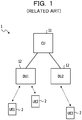
- FIG. 1 illustrates an example of such a radio base station 1.
- the CU 11 and each DU 12 are connected by a network such as an optical fiber (called a front hole).
- Each DU 12 includes at least a radio unit, and each radio unit forms a cell and performs radio communication with a radio terminal (UE: User Equipment) 2.
- UE User Equipment
- the CU 11 has a function of controlling at least a part of the scheduling of radio communication between each radio terminal 2 and each DU 12.
- scheduling of radio communication may be paraphrased as a process of determining the method of each radio communication.
- scheduling of radio communication for example, many parameters related to radio communication are determined, such as the timing of radio communication, subcarriers used for radio communication, modulation schemes and coding schemes (coding rate) applied to radio communication, and the like.
- scheduling of radio communication also includes, for example, the presence or absence of application of Coordinated Multiple Point (CoMP) transmission and reception, or determination of segmentation and concatenation of Radio Link Control (RLC) Protocol Data Unit (PDU).
- CoMP Coordinated Multiple Point
- RLC Radio Link Control
- PDU Protocol Data Unit
- one radio base station 1 may form a plurality of cells (the number of cells corresponding to the number of DUs 12). As a result, it is possible to efficiently form many cells.
- the architecture of the radio base station 1 including the CU 11 and the DU 12 as described above is referred to as "centralized type".
- a centralized radio base station 1 composed of a CU 11 and a DU 12, it is possible to efficiently form many cells.
- the inventor of the present application considers scheduling in the centralized radio base station 1 to be controversial.
- the disclosed technique is made in view of the above, and it is an object of the present invention to provide a centralized radio base station, a radio communication system, and a radio communication method capable of performing flexible scheduling.
- a radio base station includes: a first device that includes a radio unit that performs radio communication with a radio terminal and a first control unit that controls the radio communication; and a second device that is connected to the first device via a network and includes a second control unit that controls the radio communication, wherein a first scheduling function that is at least a part of a scheduling function for the radio communication of the first control unit and a second scheduling function that is at least a part of a scheduling function for the radio communication of the second control unit are redundant.
- the radio base station and the radio communication method disclosed in the present invention it is possible to perform flexible scheduling in a centralized radio base station.
- a centralized radio base station 1 composed of a CU 11 and a DU 12, it is possible to efficiently form many cells.
- scheduling of radio communication may not be flexibly performed in the centralized radio base station 1 under predetermined conditions.
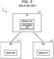
- FIG. 2 illustrates a first case where the centralized radio base station 1 composed of the CU 11 and the DU 12 performs scheduling of radio communication.
- FIG. 2 illustrates a case where the CU 11 intensively performs the scheduling of each radio communication performed by each DU 12. This is conceivable to be the most general form of scheduling in the centralized radio base station 1.
- the CU 11 includes a control unit, and the control unit includes a scheduling unit.
- each DU 12 includes a radio section.
- scheduling of radio communication may be paraphrased as a process of determining the mode of each radio communication.
- many parameters related to radio communication are determined, such as the timing of radio communication (corresponding to a subframe in LTE or the like), subcarriers used for radio communication (corresponding to a resource block in LTE or the like), modulation schemes and coding schemes applied to radio communication (Modulation and Coding Scheme (MCS)) in LTE or the like), and the like.
- scheduling of radio communication includes, for example, processing of determining whether coordinated multiple point transmission is applied, processing of controlling segmentation and reassembly (concatenation) for RLC PDUs, and the like.
- Scheduling of such radio communication is generally performed based on radio quality (quality of radio communication path).
- radio quality quality of radio communication path.
- SNR Signal-to-Noise Ratio
- SINR Signal-to-Interference plus Noise Ratio
- SNDR Signal-to-Noise plus Distortion Ratio
- the radio terminal 2 measures the radio quality based on a reference signal (standard signal, pilot signal) in downlink radio signals and transmits a feedback signal (feedback information) to the base station based on the measurement result.
- the base station may perform scheduling of downlink communication based on this feedback signal.
- This feedback signal is called Channel State Information (CSI) in LTE or the like.
- CSI for example, Channel Quality Information (CQI), Precoding Matrix Indicator (PMI), and Rank Indicator (RI) may be used.
- CSI is a type of uplink control information (UCI).
- the radio base station 1 itself may measure the radio quality based on the reference signal (standard signal) in the uplink radio signals.
- the base station may perform scheduling of the uplink communication based on the measurement result.
- scheduling of radio communication is generally performed based on radio quality. For example, for the timing of radio communication, radio communication is performed with the best possible radio quality. In addition, for subcarriers used for radio communication, radio communication is performed by using subcarriers with the best possible radio quality. Various other matters determined in the scheduling of radio communication are also based on radio quality.
- the CU 11 and each DU 12 are connected via a network called a front hole.
- a network having a relatively small delay that is, low delay or high speed
- a relatively large delay that is, high delay or low speed
- electric wire and radio a front hole with no delay or relatively small delay
- a front hole with a relatively large delay is called a non-ideal front hole.
- a non-ideal front hole may be assumed from the viewpoint of cost and the like.
- an ideal front hole and a non-ideal front hole may be mixed.
- the radio terminal 2 measures the radio quality based on a reference signal in downlink radio signals and transmits a feedback signal to the base station based on the measurement result.
- the base station performs scheduling based on the feedback signal, and a downlink radio signal (including data and the like) is transmitted based on the scheduling result.
- a feedback signal indicating the radio quality may be delivered from the radio terminal 2 (not illustrated) to the CU 11 via the DU 12.
- the front hole is non-ideal, since the propagation delay between the DU 12 and the CU 11 is relatively large, it is difficult to reflect the latest radio quality in the scheduling.
- the problem in downlink communication is pointed out, but it is to be noted that the circumstances remain unchanged even in uplink communication.
- FIG. 3 illustrates a second case where the centralized radio base station 1 performs scheduling of radio communication.
- FIG. 3 illustrates a case where each DU 12 performs scheduling of each radio communication performed by each DU 12 in a distributed manner.
- each DU 12 includes a control unit, and the control unit includes a scheduling unit.
- each DU 12 also includes a radio unit.
- the problem described with reference to FIG. 2 does not occur.
- scheduling of radio communication is performed in each DU 12 so that information related to the radio quality for scheduling and information indicating the scheduling result is not transmitted and received via the front hole.
- Examples of such a control include inter-cell interference control (ICIC) in addition to CoMP transmission and reception as described above.
- ICIC inter-cell interference control
- These techniques in LTE have been introduced with the aim of improving the characteristics of radio communication by coordinating between the cells.
- the radio base station 1 illustrated in FIG. 3 since it is difficult to perform these various kinds of control, it may be assumed that the case where the characteristics of the radio communication may not be sufficiently established occurs.
- the centralized radio base station 1 may not perform scheduling of radio communication flexibly.
- viewpoints of this deficiency may be considered, but here, as an example, the description was made from one viewpoint. Again, this deficiency has been found by a fine examination by the inventor of the present application.
- scheduling of radio communication includes various functions, and in the above description, the case where all of these various functions are implemented in either CU 11 or DU 12 is described. However, it is to be noted that even in a case where some of these various functions are implemented in the CU 11 and others are implemented in the DU 12, the above-described problem occurs at least in part.
- the first embodiment is based on the radio base station 1 includes a first device (for example, DU 12) that includes a radio unit 121 that performs radio communication with a radio terminal 2 and a first control unit 122 that controls the radio communication and a second device (for example, CU 11) that is connected to the first device via a network and includes a second control unit 111 that controls the radio communication, in which a first scheduling function that is at least a part of a scheduling function for the radio communication of the first control unit 122 and a second scheduling function that is at least a part of a scheduling function for the radio communication of the second control unit 111 are redundant.
- a first scheduling function that is at least a part of a scheduling function for the radio communication of the first control unit 122
- a second scheduling function that is at least a part of a scheduling function for the radio communication of the second control unit 111 are redundant.
- the centralized radio base station 1 as illustrated in FIGs. 2 and 3 may not perform scheduling of radio communication flexibly.
- viewpoints of this deficiency may be considered, but as an example, the description was made from two viewpoints.
- the cause of these deficiencies is that in the centralized radio base station 1 illustrated in FIG. 2 , only the CU 11 is provided with a scheduling unit (scheduling function) and in the centralized radio base station 1 illustrated in FIG. 3 , only the DU 12 is provided with a scheduling unit (scheduling function). That is, it is conceivable that the cause of these deficiencies is that, after all, in the centralized radio base station 1 illustrated in FIGs. 2 and 3 , one of the CU 11 and the DU 12 is mutually exclusively provided with a scheduling function.
- the CU 11 and the DU 12 are provided with a scheduling unit (scheduling function) redundantly. That is, the second control unit 111 in the CU 11 is provided with the scheduling unit 112, and the first control unit 122 in each DU 12 is provided with a scheduling unit 123.
- the radio base station 1 may appropriately select and use the scheduling function redundant in the CU 11 and the DU 12 according to the situation.
- the above-described deficiency in the centralized radio base station 1 illustrated in FIGs. 2 and 3 is solved.
- the "scheduling function” may be replaced with the “scheduling unit” as appropriate.
- the difference between these terms is only emphasizing the function or emphasizing the structure, and there is not much significance in considering the substantial difference.
- the base station according to the first embodiment illustrated in FIG. 4 since the CU 11 and the DU 12 are provided with the scheduling function redundantly, it is possible to use the scheduling function of the DU 12 side in a case where the front hole is non-ideal, and use the scheduling function of the CU 11 side in a case where the front hole is ideal.
- the configuration illustrated in FIG. 4 may also be expected to be advantageous at least from the other three viewpoints. All of these viewpoints were obtained from a detailed analysis of the inventor. In the following, these three viewpoints will be referred to as the second to fourth viewpoints and will be described in order.
- the CU 11 is responsible for scheduling all the DUs 12. Therefore, although the CU 11 generally has relatively large computer resources (CPU power, memory capacity, and the like), it may be assumed that the processing load of the CU 11 becomes excessively high, which may cause problems in scheduling and other processing in the CU 11.
- each DU 12 itself is responsible for scheduling for each DU 12.
- each DU 12 may only perform scheduling of radio communication by itself, but in general, the computer resources of DU 12 are relatively small. For this reason, for example, in a case where retransmission frequently occurs in the radio unit, it may be assumed that the processing load on the DU 12 increases, which may cause problems in scheduling and other processing in the DU 12.
- the radio base station 1 according to the first embodiment illustrated in FIG. 4 since the CU 11 and the DU 12 are provided with the scheduling function redundantly, it is possible to use the scheduling function of the DU 12 side in a case where the load of the CU 11 is high and to use the scheduling function of the CU 11 side in a case where the load of the DU 12 is high.
- the third viewpoint on the advantages of the radio base station 1 in FIG. 4 will be described.
- baseband processing and the like are performed by the DU 12, so that the signal of a lower layer never transmits through the front hole.
- the configuration illustrated in FIG. 2 it is also possible to perform, for example, the baseband processing with the CU 11, in which case a signal of a lower layer is transmitted in the front hole.
- the signal of the lower layer is, for example, a Layer 1 (L1) signal.
- the radio communication uses a millimeter wave (30 GHz to 300 GHz).
- the millimeter wave is high in rectilinearity and is intended for so-called line-of-sight communication, but since there are many unused bands and large capacity communication is possible, the millimeter wave is a frequency band expected to be utilized in 5G systems.
- the determination as to whether to adopt either the configuration in FIG. 2 or the configuration in FIG. 3 differs depending on the frequency band used by the radio communication.
- the configurations in FIGs. 2 and 3 have a deficiency that the configurations may not sufficiently deal with only one of the millimeter wave band and the frequency band in the related art. Further, the configurations in FIGs. 2 and 3 may not dynamically cope with the change of the frequency band used by radio communication.
- the radio base station 1 according to the first embodiment illustrated in FIG. 4 since the CU 11 and the DU 12 are provided with the scheduling function redundantly, it is possible to use the scheduling function of the DU 12 side in a case where radio communication uses the millimeter wave and to use the scheduling function of the CU 11 side in a case where the radio communication uses the frequency band of the cellular communication in the related art.
- the radio base station 1 according to the first embodiment illustrated in FIG. 4 since the CU 11 and the DU 12 are provided with the scheduling function redundantly, it is possible to use the scheduling function of the DU 12 side in a case where radio communication uses the millimeter wave and to use the scheduling function of the CU 11 side in a case where the radio communication uses the frequency band of the cellular communication in the related art.
- the configuration in FIG. 3 is preferable in a case where the front hole is non-ideal.
- traffic for example, traffic by smart meters in IoT (Internet of Things)
- IoT Internet of Things
- actual damage is small. Therefore, even if the front hole is non-ideal, it is conceivable that there is no problem in adopting the configuration in FIG. 2 for traffic that may tolerate a delay.
- traffic that may not tolerate delay such as real-time data
- the configuration in FIG. 3 is preferable in principle.
- the radio base station 1 according to the first embodiment illustrated in FIG. 4 since the CU 11 and the DU 12 are provided with the scheduling function redundantly, it is possible to use the scheduling function of the CU 11 side in a case where the traffic may tolerate the delay and to use the scheduling function of the DU 12 side in a case where the traffic may not tolerate the delay.
- the radio base station 1 according to the first embodiment illustrated in FIG. 4 it is possible to raise the priority of using the scheduling function of the CU 11 side in a case where the traffic may tolerate the delay and to raise the priority of using the scheduling function of the DU 12 side in a case where the traffic may not tolerate the delay.
- the scheduling of radio communication includes various functions, and in the radio base station 1 according to the first embodiment, it goes without saying that all of these various functions may be provided redundantly in the CU 11 and the DU 12. However, in the radio base station 1 according to the first embodiment, it is to be noted that at least some of these various functions may be provided redundantly in the CU 11 and the DU 12.
- the scheduling function is generally configured hierarchically in general, but among the scheduling functions, functions of a relatively lower layer may be provided redundantly in the CU 11 and the DU 12, and other relatively higher layer functions may be provided only in the CU 11. As a result, it is possible to obtain the effect of the present invention with respect to the functions of the relatively lower layer which are provided redundantly by the CU 11 and the DU 12.
- the first embodiment described above it is possible to solve the deficiencies in the centralized type radio base station 1 from the two viewpoints regarding the flexibility of the radio scheduling described above. Therefore, according to the first embodiment, a remarkable effect that it is possible to perform scheduling of radio communication flexibility is exerted, which is not obtained in the related art.
- the second embodiment is the radio base station 1 according to the first embodiment, and the second control unit 111 is based on the radio base station 1 that selects which one of the first scheduling function and the second scheduling function performs scheduling of the radio communication.
- the scheduling function of radio communication is provided redundantly in the CU 11 and the DU 12.
- the radio base station 1 according to the second embodiment is an added configuration in which the CU 11 dynamically selects which one of the CU 11 side and the DU 12 side to use the scheduling function under the premise of the base station according to the first embodiment.
- FIG. 5 illustrates the radio base station 1 according to the second embodiment.
- the radio base station 1 illustrated in FIG. 5 is different from the radio base station 1 illustrated in FIG. 4 in that a selection unit 113 is added to the second control unit 111 on the CU 11 side.
- the selection unit 113 selects which one of the CU 11 side and the DU 12 side to use the scheduling function.
- the above selection made by the CU 11 may be made based on various criteria.
- selection criteria in accordance with the above-described first viewpoint, the CU 11 may select the DU 12 side in a case where the front hole is non-ideal and may select the CU 11 side in a case where the front hole is ideal.
- the front hole is non-ideal or ideal, but this may be determined based on the type of the communication interface of the front hole, or it may be determined based on the communication delay of the front hole or the measured value of the Round Trip Time (RTT).
- RTT Round Trip Time
- the CU 11 may select the DU 12 side in a case where the load of the CU 11 is high (for example, in the case of being equal to or greater than a first predetermined value) and may select the CU 11 side in a case where the load of the DU 12 is high (for example, generally, in the case of being equal to or greater than a second predetermined value smaller than the first predetermined value).
- index values may be used as the load of the CU 11 and the DU 12, and for example, a CPU usage rate, a memory usage rate, or the like may be used. In addition, for example, it is possible to determine the load of the CU 11 or the DU 12 based on the number of the connected radio terminals 2.
- either the scheduling function of CU 11 or DU 12 may be used, but in such a case, for example, the scheduling function of CU 11 may be fixedly used.
- the scheduling function of CU 11 may be fixedly used.
- the CU 11 may select the DU 12 side in a case where the radio communication uses the millimeter wave and may select the CU 11 side in a case where the radio communication uses the frequency band of the cellular communication in the related art.
- the radio communication uses the millimeter wave
- the CU 11 may select the CU 11 side in a case where the traffic may tolerate the delay and may select the DU 12 side in a case where the traffic may not tolerate the delay.
- the criteria of the above four selections may be used alone, or some of the criteria may be combined.
- the priority (standard weight) in the case of combining several criteria may be adjusted as appropriate.
- the scheduling function of the one selected from the CU 11 side and the DU 12 side is activated.
- the scheduling function of the one of the CU 11 side and the DU 12 side which has not been selected has already been activated
- the scheduling function is deactivated.
- the CU 11 may notify or transmit information or a signal instructing that the activating or stopping to the DU 12 via the front hole.
- the CU 11 may perform the scheduling of radio communication performed by the DU 12 in a fixed manner by the CU 11.
- the above selection unit may be selected appropriately and may be, for example, a traffic flow unit or a bearer unit.
- the scheduling function in the base station includes, for example, the functions of selection (routing) of DU 12, segmentation or concatenation of upper packets, adaptive modulation coding (AMC: Adaptive Modulation and Coding), and other functions (for example, radio resource selection, transmission data amount selection, selection of the radio terminal 2 for performing communication, and the like).
- AMC adaptive modulation coding
- other functions for example, radio resource selection, transmission data amount selection, selection of the radio terminal 2 for performing communication, and the like.
- the selection function (routing) of the DU 12 is naturally provided by the CU 11.
- the CU 11 or the DU 12 is provided with segmentation or concatenation function and the functions such as AMC and the like.
- segmentation or concatenation function, and functions such as AMC and the like are provided redundantly in both the CU 11 and the DU 12.
- an adaptation function has been added, but this is a function that is not provided in the radio base station 1 such as the LTE system in the related art.
- the adaptation function is a function of selecting one of the CU 11 and the DU 12 based on various criteria, and the adaptation function on the CU 11 side, in particular, corresponds to the selection unit 113 in the second embodiment.
- each scheduling function in the radio base station 1 according to the third embodiment operates in accordance with the selection criteria based on the above-described first viewpoint. It goes without saying that the other selection criteria described above may be considered similarly to the description below.
- FIG. 7 is a diagram illustrating an example of the state of the operation of the radio base station 1 according to the third embodiment in a case where both of the two front holes are ideal.
- the dot pattern portion indicates the activated scheduling function
- the shaded pattern portion indicates the deactivated scheduling function.
- all functions of routing, segmentation or concatenation functions, AMC, and the like in the CU 11 are activated, and all functions of segmentation or concatenation function, AMC, and the like in the DU 12 are all stopped. Activation and stop of each function are controlled by an adaptation function.
- FIG. 8 is a diagram illustrating another example of the state of the operation of the radio base station 1 according to the third embodiment in a case where both of the two front holes are ideal.
- functions of routing, segmentation or concatenation in the CU 11 are activated, and functions such as AMC and the like in the CU 11 are stopped.
- the segmentation or concatenation function in the DU 12 is stopped, and functions such as AMC and the like in the CU 11 are activated. Activation and stop of each function are controlled by an adaptation function.
- FIG. 9 is a diagram illustrating an example of the state of the operation of the radio base station 1 according to the third embodiment in a case where both of the two front holes are non-ideal.
- routing in the CU 11 is activated, and segmentation or concatenation function, and functions such as AMC and the like in the CU 11 are stopped.
- the segmentation or concatenation function in the DU 12 and the functions such as AMC and the like are activated. Activation and stop of each function are controlled by an adaptation function.
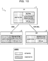
- FIG. 10 is a diagram illustrating an example of the state of the operation of the radio base station 1 according to the third embodiment in a case where one of the two front holes is ideal and the other is non-ideal.
- routing in the CU 11 is activated.
- the segmentation or concatenation function in the CU 11 and the functions such as AMC are also activated, and the segmentation or concatenation function in the DU 12 and the functions such as AMC are stopped.
- the segmentation or concatenation function in the CU 11 and the functions such as AMC are stopped, and the segmentation or concatenation function in the DU 12 and the functions such as AMC are activated.
- Activation and stop of each function are controlled by an adaptation function.
- FIG. 11 is a diagram illustrating an example of a hardware configuration of the radio base station 1.
- the radio base station 1 is provided with a CU 11 and each DU 12, and a network (front hole) is connected therebetween.
- the CU 11 is provided with, for example, a processor 1111, a memory 1112, and a communication IF (interface) 1113.
- each DU 12 is provided with, for example, a processor 1121, a memory 1122, a communication IF 1123, an RF circuit 1124, and an antenna 1125.
- the processor 1111 provided in the CU 11 and the processor 1121 provided in each DU 12 are, for example, a Central Processing Unit (CPU) or a Digital Signal Processor (DSP).
- the processor 1111 provided in the CU 11 and the processor 1121 provided in each DU 12 may be realized by a digital electronic circuit. Examples of the digital electronic circuit include Field-Programming Gate Array (FPGA), Application Specific Integrated Circuit (ASIC), Large Scale Integration (LSI), and the like.
- FPGA Field-Programming Gate Array
- ASIC Application Specific Integrated Circuit
- LSI Large Scale Integration
- the memory 1112 provided in the CU 11 and the memory 1121 provided in each DU 12 include at least one of Random Access Memory (RAM) such as Synchronous Dynamic Random Access Memory (SDRAM), a Read Only Memory (ROM), and a flash memory and store programs, control information, and data.
- RAM Random Access Memory
- SDRAM Synchronous Dynamic Random Access Memory
- ROM Read Only Memory
- flash memory stores programs, control information, and data.
- the radio base station 11 may be provided with an auxiliary storage device (hard disk or the like) not illustrated and the like.
- the communication IF 1113 provided in the CU 11 and the communication IF 1123 provided in each DU 12 are communication interfaces using, for example, an optical fiber, electric wire, radio, or the like.
- the second control unit 111 in the CU 11 is realized by, for example, a processor 1111, a memory 1112, a digital electronic circuit (not illustrated), and the like.
- the radio unit 121 in each DU 12 is realized by, for example, an RF circuit 1124, an antenna 1125, an analog electronic circuit (not illustrated), and the like.
- the first control unit 122 in the DU 12 is realized by, for example, a processor 1121, a memory 1122, a digital electronic circuit (not illustrated), and the like.
Landscapes
- Engineering & Computer Science (AREA)
- Computer Networks & Wireless Communication (AREA)
- Signal Processing (AREA)
- Mobile Radio Communication Systems (AREA)
Abstract
Description
- The present invention relates to a radio base station, a central apparatus, and a distributed apparatus.
- In recent years, in a radio communication system such as a cellular phone system (cellular system) or the like, the discussion is being made on the next generation radio communication technology in order to further increase the speed and capacity of radio communication and the like. For example, in 3rd Generation Partnership Project (3GPP) which is a standardization organization, communication standard called Long Term Evolution (LTE) and communication standard called LTE-Advanced (LTE-A) based on LTE radio communication technology are proposed, and these standards are known as the 4th generation mobile communication system (so-called 4G system). In addition, in September 2015, discussion on standardization of the 5th generation mobile communication system (so-called 5G system) following these standards has started full-scale in 3GPP.
- On the other hand, cellular systems such as LTE are already widely used, but these systems are made by many radio base stations forming many cells. Therefore, in recent years, many radio base stations have been installed everywhere.
- As a technique for efficiently forming many cells in the related art, a technique in which one radio base station forms a plurality of cells is known. Examples of such a radio base station include a radio base station composed of one central unit (CU: Central Unit) and one or more distributed units (DU). The DU is sometimes called a remote unit (RU).
-
FIG. 1 illustrates an example of such aradio base station 1. InFIG. 1 , the CU 11 and eachDU 12 are connected by a network such as an optical fiber (called a front hole). EachDU 12 includes at least a radio unit, and each radio unit forms a cell and performs radio communication with a radio terminal (UE: User Equipment) 2. On the other hand, theCU 11 has a function of controlling at least a part of the scheduling of radio communication between eachradio terminal 2 and eachDU 12. - Here, the scheduling of radio communication may be paraphrased as a process of determining the method of each radio communication. In the scheduling of radio communication, for example, many parameters related to radio communication are determined, such as the timing of radio communication, subcarriers used for radio communication, modulation schemes and coding schemes (coding rate) applied to radio communication, and the like. In addition, in a broad meaning, scheduling of radio communication also includes, for example, the presence or absence of application of Coordinated Multiple Point (CoMP) transmission and reception, or determination of segmentation and concatenation of Radio Link Control (RLC) Protocol Data Unit (PDU).
- According to the
radio base station 1 as illustrated inFIG. 1 , oneradio base station 1 may form a plurality of cells (the number of cells corresponding to the number of DUs 12). As a result, it is possible to efficiently form many cells. For the sake of convenience, in the present application, the architecture of theradio base station 1 including theCU 11 and theDU 12 as described above is referred to as "centralized type". - As described above, according to a centralized
radio base station 1 composed of aCU 11 and aDU 12, it is possible to efficiently form many cells. However, the inventor of the present application considers scheduling in the centralizedradio base station 1 to be controversial. - In particular, as a result of examination by the inventor of the present application, as described later, it has been found that there is a deficiency that flexible scheduling may not be performed in the centralized
radio base station 1 under predetermined conditions. - Although the description leading to the above problem has been made based on LTE, this problem also applies to other radio communication systems if the predetermined conditions are met.
- The disclosed technique is made in view of the above, and it is an object of the present invention to provide a centralized radio base station, a radio communication system, and a radio communication method capable of performing flexible scheduling.
- According to an aspect of the invention, a radio base station includes: a first device that includes a radio unit that performs radio communication with a radio terminal and a first control unit that controls the radio communication; and a second device that is connected to the first device via a network and includes a second control unit that controls the radio communication, wherein a first scheduling function that is at least a part of a scheduling function for the radio communication of the first control unit and a second scheduling function that is at least a part of a scheduling function for the radio communication of the second control unit are redundant.
- According to one viewpoint of the radio base station and the radio communication method disclosed in the present invention, it is possible to perform flexible scheduling in a centralized radio base station.
-
-
FIG. 1 is a diagram illustrating a centralized radio base station. -
FIG. 2 is a diagram illustrating an example of a functional configuration of a centralized radio base station. -
FIG. 3 is a diagram illustrating another example of the functional configuration in the centralized radio base station. -
FIG. 4 is a diagram illustrating the functional configuration of a radio base station according to a first embodiment. -
FIG. 5 is a diagram illustrating a functional configuration of a radio base station according to a second embodiment. -
FIG. 6 is a diagram illustrating a functional configuration of a radio base station according to a third embodiment. -
FIG. 7 is a diagram illustrating an operation example (part 1) of each function in the radio base station according to the third embodiment. -
FIG. 8 is a diagram illustrating an operation example (part 2) of each function in the radio base station according to the third embodiment. -
FIG. 9 is a diagram illustrating an operation example (part 3) of each function in the radio base station according to the third embodiment. -
FIG. 10 is a diagram illustrating an operation example (part 4) of each function in the radio base station according to the third embodiment. -
FIG. 11 is an example of a hardware configuration diagram of a radio base station according to each embodiment. - Before describing each embodiment, the location of the problem in the related art will be explained first. It is noted that this problem was newly discovered as a result of a detailed study of the related art by the inventor of the present invention and has not been known in the past.
- As described above, according to a centralized
radio base station 1 composed of aCU 11 and aDU 12, it is possible to efficiently form many cells. However, as a result of examination by the inventor of the present invention, as described later, it has been found that there is a case that scheduling of radio communication may not be flexibly performed in the centralizedradio base station 1 under predetermined conditions. - Several viewpoints of this deficiency may be considered, but here one viewpoint will be described as an example.
-
FIG. 2 illustrates a first case where the centralizedradio base station 1 composed of the CU 11 and the DU 12 performs scheduling of radio communication.FIG. 2 illustrates a case where theCU 11 intensively performs the scheduling of each radio communication performed by eachDU 12. This is conceivable to be the most general form of scheduling in the centralizedradio base station 1. - In
FIG. 2 , theCU 11 includes a control unit, and the control unit includes a scheduling unit. In addition, eachDU 12 includes a radio section. - In the drawings of the present application, the case where two DUs 12 (DU 121 and DU 122) are connected to one
CU 11 is illustrated, but it is obvious that the number ofDUs 12 connected to oneCU 11 may not be fixed. In addition, in each drawing of the present application, functions other than functions that are basic for describing the present invention (for example, baseband (BB) processing function, and the like) are omitted, but it goes without saying that this point does not mean that theradio base station 1 or the like illustrated in each drawing does not have such omitted functions. - Here, this paper revisits the definition of scheduling of radio communication. As described above, the scheduling of radio communication may be paraphrased as a process of determining the mode of each radio communication. In the scheduling of radio communication, for example, many parameters related to radio communication are determined, such as the timing of radio communication (corresponding to a subframe in LTE or the like), subcarriers used for radio communication (corresponding to a resource block in LTE or the like), modulation schemes and coding schemes applied to radio communication (Modulation and Coding Scheme (MCS)) in LTE or the like), and the like. In addition, in a broad meaning, scheduling of radio communication includes, for example, processing of determining whether coordinated multiple point transmission is applied, processing of controlling segmentation and reassembly (concatenation) for RLC PDUs, and the like.
- Scheduling of such radio communication is generally performed based on radio quality (quality of radio communication path). For example, Signal-to-Noise Ratio (SNR), Signal-to-Interference plus Noise Ratio (SINR), Signal-to-Noise plus Distortion Ratio (SNDR), or the like may be used as the radio quality.
- In the case of downlink communication, the
radio terminal 2 measures the radio quality based on a reference signal (standard signal, pilot signal) in downlink radio signals and transmits a feedback signal (feedback information) to the base station based on the measurement result. The base station may perform scheduling of downlink communication based on this feedback signal. This feedback signal is called Channel State Information (CSI) in LTE or the like. As the CSI, for example, Channel Quality Information (CQI), Precoding Matrix Indicator (PMI), and Rank Indicator (RI) may be used. CSI is a type of uplink control information (UCI). - On the other hand, in the case of uplink communication, the
radio base station 1 itself may measure the radio quality based on the reference signal (standard signal) in the uplink radio signals. The base station may perform scheduling of the uplink communication based on the measurement result. - In any case, scheduling of radio communication is generally performed based on radio quality. For example, for the timing of radio communication, radio communication is performed with the best possible radio quality. In addition, for subcarriers used for radio communication, radio communication is performed by using subcarriers with the best possible radio quality. Various other matters determined in the scheduling of radio communication are also based on radio quality.
- As described above, in the centralized
radio base station 1, theCU 11 and eachDU 12 are connected via a network called a front hole. Here, as the front hole, it is desirable to use a network having a relatively small delay (that is, low delay or high speed) such as an optical fiber or the like. However, in some cases, as the front hole, there are cases where it is inevitable to use a network having a relatively large delay (that is, high delay or low speed) such as electric wire and radio. In general, a front hole with no delay or relatively small delay is called an ideal front hole, and a front hole with a relatively large delay is called a non-ideal front hole. - For example, in developing countries and the like, a non-ideal front hole may be assumed from the viewpoint of cost and the like. Of course, in one
radio base station 1, an ideal front hole and a non-ideal front hole may be mixed. - The case where the front hole is non-ideal in the centralized
radio base station 1 will be examined. - As described above, for example, in the case of downlink communication, the
radio terminal 2 measures the radio quality based on a reference signal in downlink radio signals and transmits a feedback signal to the base station based on the measurement result. The base station performs scheduling based on the feedback signal, and a downlink radio signal (including data and the like) is transmitted based on the scheduling result. Here, inFIG. 2 , since scheduling is performed by theCU 11, a feedback signal indicating the radio quality may be delivered from the radio terminal 2 (not illustrated) to theCU 11 via theDU 12. However, in a case where the front hole is non-ideal, since the propagation delay between theDU 12 and theCU 11 is relatively large, it is difficult to reflect the latest radio quality in the scheduling. Here, the problem in downlink communication is pointed out, but it is to be noted that the circumstances remain unchanged even in uplink communication. - Therefore, in the centralized
radio base station 1 as illustrated inFIG. 2 , in a case where the front hole is non-ideal, there is a problem that it is difficult to perform scheduling reflecting the latest radio quality. - Next,
FIG. 3 illustrates a second case where the centralizedradio base station 1 performs scheduling of radio communication.FIG. 3 illustrates a case where eachDU 12 performs scheduling of each radio communication performed by eachDU 12 in a distributed manner. - In
FIG. 3 , eachDU 12 includes a control unit, and the control unit includes a scheduling unit. In addition, eachDU 12 also includes a radio unit. - In the
radio base station 1 illustrated inFIG. 3 , even if the front hole is non-ideal, it is conceivable that the problem described with reference toFIG. 2 does not occur. In theradio base station 1 illustrated inFIG. 3 , scheduling of radio communication is performed in eachDU 12 so that information related to the radio quality for scheduling and information indicating the scheduling result is not transmitted and received via the front hole. - However, it is conceivable that other problems may occur in the
radio base station 1 illustrated inFIG. 3 . Specifically, in theradio base station 1 illustrated inFIG. 3 , since the scheduling of radio communication is performed within eachDU 12 in a closed manner, scheduling is performed independently for each cell. For this reason, it is difficult for theradio base station 1 illustrated inFIG. 3 to perform various kinds of control for coordinating between the cells. - Examples of such a control include inter-cell interference control (ICIC) in addition to CoMP transmission and reception as described above. These techniques in LTE have been introduced with the aim of improving the characteristics of radio communication by coordinating between the cells. In the
radio base station 1 illustrated inFIG. 3 , since it is difficult to perform these various kinds of control, it may be assumed that the case where the characteristics of the radio communication may not be sufficiently established occurs. - Therefore, in the centralized type illustrated in
FIG. 2 , in a case where the front hole is non-ideal, it is difficult to perform scheduling reflecting the latest radio quality. On the other hand, in the centralized type illustrated inFIG. 3 , it is difficult to perform various kinds of control for coordinating between the cells. Therefore, even if either of the configurations inFIGs. 2 and3 is adopted for the centralizedradio base station 1, it is conceivable that any of these problems will occur. This point is one viewpoint regarding the scheduling flexibility in the above-described centralizedradio base station 1. - To summarize the above, there is a deficiency that the centralized
radio base station 1 may not perform scheduling of radio communication flexibly. Several viewpoints of this deficiency may be considered, but here, as an example, the description was made from one viewpoint. Again, this deficiency has been found by a fine examination by the inventor of the present application. - As described above, scheduling of radio communication includes various functions, and in the above description, the case where all of these various functions are implemented in either
CU 11 orDU 12 is described. However, it is to be noted that even in a case where some of these various functions are implemented in theCU 11 and others are implemented in theDU 12, the above-described problem occurs at least in part. - In addition, the above description has been made based on LTE or the like, but it is to be noted that this description also applies to other radio communication systems if the predetermined conditions are met.
- In the following, various embodiments for solving the above problem will be described one by one in order.
- The first embodiment is based on the
radio base station 1 includes a first device (for example, DU 12) that includes aradio unit 121 that performs radio communication with aradio terminal 2 and afirst control unit 122 that controls the radio communication and a second device (for example, CU 11) that is connected to the first device via a network and includes asecond control unit 111 that controls the radio communication, in which a first scheduling function that is at least a part of a scheduling function for the radio communication of thefirst control unit 122 and a second scheduling function that is at least a part of a scheduling function for the radio communication of thesecond control unit 111 are redundant. - The technical significance of the first embodiment will be explained. As described above, there is a deficiency that the centralized
radio base station 1 as illustrated inFIGs. 2 and3 may not perform scheduling of radio communication flexibly. Several viewpoints of this deficiency may be considered, but as an example, the description was made from two viewpoints. - It is conceivable that the cause of these deficiencies is that in the centralized
radio base station 1 illustrated inFIG. 2 , only theCU 11 is provided with a scheduling unit (scheduling function) and in the centralizedradio base station 1 illustrated inFIG. 3 , only theDU 12 is provided with a scheduling unit (scheduling function). That is, it is conceivable that the cause of these deficiencies is that, after all, in the centralizedradio base station 1 illustrated inFIGs. 2 and3 , one of theCU 11 and theDU 12 is mutually exclusively provided with a scheduling function. - Therefore, in the centralized
radio base station 1 according to the first embodiment, as illustrated inFIG. 4 , it is assumed that theCU 11 and theDU 12 are provided with a scheduling unit (scheduling function) redundantly. That is, thesecond control unit 111 in theCU 11 is provided with thescheduling unit 112, and thefirst control unit 122 in eachDU 12 is provided with ascheduling unit 123. By doing so, theradio base station 1 may appropriately select and use the scheduling function redundant in theCU 11 and theDU 12 according to the situation. As a result, it is conceivable that the above-described deficiency in the centralizedradio base station 1 illustrated inFIGs. 2 and3 is solved. - In the following description, the "scheduling function" may be replaced with the "scheduling unit" as appropriate. The difference between these terms is only emphasizing the function or emphasizing the structure, and there is not much significance in considering the substantial difference.
- The technical significance of the radio base station according to the first embodiment illustrated in
FIG. 4 will be described more specifically. In the base station illustrated inFIGs. 2 and3 , as described above, for example, there is a deficiency from one viewpoint. - On the other hand, according to the base station according to the first embodiment illustrated in
FIG. 4 , since theCU 11 and theDU 12 are provided with the scheduling function redundantly, it is possible to use the scheduling function of theDU 12 side in a case where the front hole is non-ideal, and use the scheduling function of theCU 11 side in a case where the front hole is ideal. Alternatively, according to the base station according to the first embodiment illustrated inFIG. 4 , it is possible to raise the priority of using the scheduling function of theDU 12 side in a case where the front hole is non-ideal and to raise the priority of using the scheduling function of theCU 11 side in a case where the front hole is ideal. As a result, in a case where the front hole is non-ideal, it is possible to perform scheduling reflecting the latest radio quality by the scheduling function on theDU 12 side. In addition, in a case where the front hole is ideal, it is possible to perform various kinds of control to coordinate between the cells by the scheduling function of theCU 11 side. Therefore, according to the base station according to the first embodiment illustrated inFIG. 4 , it is conceivable that the deficiency from one viewpoint described with reference toFIGs. 2 and3 may be solved. - In addition to the first viewpoint described above, it is considered that the configuration illustrated in
FIG. 4 may also be expected to be advantageous at least from the other three viewpoints. All of these viewpoints were obtained from a detailed analysis of the inventor. In the following, these three viewpoints will be referred to as the second to fourth viewpoints and will be described in order. - First, the second viewpoint on advantages of the
radio base station 1 inFIG. 4 will be described. In theradio base station 1 illustrated inFIG. 2 described above, theCU 11 is responsible for scheduling all theDUs 12. Therefore, although theCU 11 generally has relatively large computer resources (CPU power, memory capacity, and the like), it may be assumed that the processing load of theCU 11 becomes excessively high, which may cause problems in scheduling and other processing in theCU 11. - On the other hand, in the centralized type illustrated in
FIG. 3 described above, eachDU 12 itself is responsible for scheduling for eachDU 12. In this case, eachDU 12 may only perform scheduling of radio communication by itself, but in general, the computer resources ofDU 12 are relatively small. For this reason, for example, in a case where retransmission frequently occurs in the radio unit, it may be assumed that the processing load on theDU 12 increases, which may cause problems in scheduling and other processing in theDU 12. - Therefore, even if either of the configurations in
FIGs. 2 and3 is adopted for the centralizedradio base station 1, it is conceivable that the problem of the processing load of theCU 11 or the processing load of theDU 12 occurs. Further, the configurations inFIGs. 2 and3 may not dynamically cope with a change in the processing load inCU 11 orDU 12. This means that the configurations inFIGs. 2 and3 have a deficiency in that the scheduling flexibility of the centralizedradio base station 1 lacks. - On the other hand, according to the
radio base station 1 according to the first embodiment illustrated inFIG. 4 , since theCU 11 and theDU 12 are provided with the scheduling function redundantly, it is possible to use the scheduling function of theDU 12 side in a case where the load of theCU 11 is high and to use the scheduling function of theCU 11 side in a case where the load of theDU 12 is high. Alternatively, according to theradio base station 1 according to the first embodiment illustrated inFIG. 4 , it is possible to raise the priority of using the scheduling function of theDU 12 side in a case where the load of theCU 11 is high and to raise the priority of using the scheduling function of theCU 11 side in a case where the load of theDU 12 is high. As a result, in a case where the load of theCU 11 is high, it is possible to avoid further overloading of theCU 11 due to load distribution. In addition, even in a case where the load of theDU 12 is high, it is possible to avoid further overloading of theDU 12 due to load distribution. In addition, according to the configuration ofFIG. 4 , it is possible to dynamically cope with a change in the processing load inCU 11 orDU 12. Therefore, according to the base station according to the first embodiment illustrated inFIG. 4 , it is conceivable that the above-described deficiency may be solved. - Next, the third viewpoint on the advantages of the
radio base station 1 inFIG. 4 will be described. In the configuration illustrated inFIG. 3 , baseband processing and the like are performed by theDU 12, so that the signal of a lower layer never transmits through the front hole. On the other hand, in the configuration illustrated inFIG. 2 , it is also possible to perform, for example, the baseband processing with theCU 11, in which case a signal of a lower layer is transmitted in the front hole. The signal of the lower layer is, for example, a Layer 1 (L1) signal. - Therefore, in a case where the amount of the signal of the low layer becomes enormous, even if the advantage of the configuration of
FIG. 2 (inter-cell coordinating control and the like) is lost, it is conceivable that the configuration ofFIG. 3 may be preferable to the configuration ofFIG. 2 . As an example of such a case, it is conceivable that the radio communication uses a millimeter wave (30 GHz to 300 GHz). The millimeter wave is high in rectilinearity and is intended for so-called line-of-sight communication, but since there are many unused bands and large capacity communication is possible, the millimeter wave is a frequency band expected to be utilized in 5G systems. - On the other hand, in the frequency band (700 MHz band to 3.5 GHz band used in the 4G system) of the cellular communication in the related art, since there are no special circumstances like millimeter waves, it is conceivable that in principle, it is desirable to enjoy the advantages of the configuration of
FIG. 2 . - As described above, it is conceivable that the determination as to whether to adopt either the configuration in
FIG. 2 or the configuration inFIG. 3 differs depending on the frequency band used by the radio communication. However, the configurations inFIGs. 2 and3 have a deficiency that the configurations may not sufficiently deal with only one of the millimeter wave band and the frequency band in the related art. Further, the configurations inFIGs. 2 and3 may not dynamically cope with the change of the frequency band used by radio communication. - On the other hand, according to the
radio base station 1 according to the first embodiment illustrated inFIG. 4 , since theCU 11 and theDU 12 are provided with the scheduling function redundantly, it is possible to use the scheduling function of theDU 12 side in a case where radio communication uses the millimeter wave and to use the scheduling function of theCU 11 side in a case where the radio communication uses the frequency band of the cellular communication in the related art. Alternatively, according to theradio base station 1 according to the first embodiment illustrated inFIG. 4 , it is possible to raise the priority of using the scheduling function of theDU 12 side in a case where the radio communication uses the millimeter wave and to raise the priority of using the scheduling function of theCU 11 side in a case where the radio communication uses the cellular communication frequency band in the related art. In addition, according to the configuration ofFIG. 4 , it is possible to dynamically cope with a change in the frequency band used by wireless communication. Therefore, according to the base station according to the first embodiment illustrated inFIG. 4 , it is conceivable that the above-described deficiency may be solved. - Finally, the fourth viewpoint on the advantages of the
radio base station 1 inFIG. 4 will be described. Although not considered specifically in the examination made so far, it is conceivable that the determination as to whether to adopt either the configuration inFIG. 2 or the configuration inFIG. 3 will be different depending on the characteristics or attributes of traffic (data). - For example, as described above, in principle, it is conceivable that the configuration in
FIG. 3 is preferable in a case where the front hole is non-ideal. However, for example, for traffic (for example, traffic by smart meters in IoT (Internet of Things)) that may tolerate a certain degree of delay, even if retransmission is repeated without being able to perform scheduling based on the latest radio quality, it is conceivable that actual damage is small. Therefore, even if the front hole is non-ideal, it is conceivable that there is no problem in adopting the configuration inFIG. 2 for traffic that may tolerate a delay. On the other hand, for traffic that may not tolerate delay, such as real-time data, in a case where the front hole is non-ideal, it is conceivable that the configuration inFIG. 3 is preferable in principle. - In this way, it is conceivable that the determination as to whether to adopt either the configuration in
FIG. 2 or the configuration inFIG. 3 will be different depending on the characteristics or attributes of the traffic. However, the configurations inFIGs. 2 and3 have a deficiency that it is not possible to deal with such a determination sufficiently. Further, the configurations inFIGs. 2 and3 may not dynamically cope with changes in traffic characteristics or attributes. - On the other hand, according to the
radio base station 1 according to the first embodiment illustrated inFIG. 4 , since theCU 11 and theDU 12 are provided with the scheduling function redundantly, it is possible to use the scheduling function of theCU 11 side in a case where the traffic may tolerate the delay and to use the scheduling function of theDU 12 side in a case where the traffic may not tolerate the delay. Alternatively, according to theradio base station 1 according to the first embodiment illustrated inFIG. 4 , it is possible to raise the priority of using the scheduling function of theCU 11 side in a case where the traffic may tolerate the delay and to raise the priority of using the scheduling function of theDU 12 side in a case where the traffic may not tolerate the delay. In addition, according to the configuration inFIG. 4 , it is possible to dynamically cope with changes in traffic characteristics or attributes. Therefore, according to the base station according to the first embodiment illustrated inFIG. 4 , it is conceivable that the above-described deficiency may be solved. - In addition, as described above, the scheduling of radio communication includes various functions, and in the
radio base station 1 according to the first embodiment, it goes without saying that all of these various functions may be provided redundantly in theCU 11 and theDU 12. However, in theradio base station 1 according to the first embodiment, it is to be noted that at least some of these various functions may be provided redundantly in theCU 11 and theDU 12. As an example, the scheduling function is generally configured hierarchically in general, but among the scheduling functions, functions of a relatively lower layer may be provided redundantly in theCU 11 and theDU 12, and other relatively higher layer functions may be provided only in theCU 11. As a result, it is possible to obtain the effect of the present invention with respect to the functions of the relatively lower layer which are provided redundantly by theCU 11 and theDU 12. - According to the first embodiment described above, it is possible to solve the deficiencies in the centralized type
radio base station 1 from the two viewpoints regarding the flexibility of the radio scheduling described above. Therefore, according to the first embodiment, a remarkable effect that it is possible to perform scheduling of radio communication flexibility is exerted, which is not obtained in the related art. - The second embodiment is the
radio base station 1 according to the first embodiment, and thesecond control unit 111 is based on theradio base station 1 that selects which one of the first scheduling function and the second scheduling function performs scheduling of the radio communication. - As described above, in the
radio base station 1 according to the first embodiment, the scheduling function of radio communication is provided redundantly in theCU 11 and theDU 12. Theradio base station 1 according to the second embodiment is an added configuration in which theCU 11 dynamically selects which one of theCU 11 side and theDU 12 side to use the scheduling function under the premise of the base station according to the first embodiment. -
FIG. 5 illustrates theradio base station 1 according to the second embodiment. Theradio base station 1 illustrated inFIG. 5 is different from theradio base station 1 illustrated inFIG. 4 in that aselection unit 113 is added to thesecond control unit 111 on theCU 11 side. Theselection unit 113 selects which one of theCU 11 side and theDU 12 side to use the scheduling function. - The above selection made by the
CU 11 may be made based on various criteria. As an example of selection criteria, in accordance with the above-described first viewpoint, theCU 11 may select theDU 12 side in a case where the front hole is non-ideal and may select theCU 11 side in a case where the front hole is ideal. Alternatively, it is possible to raise the priority of selecting theDU 12 side in a case where the front hole is non-ideal and to raise the priority of selecting theCU 11 side in a case where the front hole is ideal. - In this case, it is mandatory to determine whether the front hole is non-ideal or ideal, but this may be determined based on the type of the communication interface of the front hole, or it may be determined based on the communication delay of the front hole or the measured value of the Round Trip Time (RTT).
- In addition, as another example of the selection criterion, in accordance with the second viewpoint described above, the
CU 11 may select theDU 12 side in a case where the load of theCU 11 is high (for example, in the case of being equal to or greater than a first predetermined value) and may select theCU 11 side in a case where the load of theDU 12 is high (for example, generally, in the case of being equal to or greater than a second predetermined value smaller than the first predetermined value). Alternatively, it is possible to raise the priority of selecting theDU 12 side in a case where the load of theCU 11 is high and to raise the priority of selecting theCU 11 side in a case where the load of theDU 12 is high. - Various index values may be used as the load of the
CU 11 and theDU 12, and for example, a CPU usage rate, a memory usage rate, or the like may be used. In addition, for example, it is possible to determine the load of theCU 11 or theDU 12 based on the number of theconnected radio terminals 2. - Under the premise that the above selection is made based on the load of
CU 11 orDU 12, in a case where loads ofCU 11 andDU 12 are both low, either the scheduling function ofCU 11 orDU 12 may be used, but in such a case, for example, the scheduling function ofCU 11 may be fixedly used. In addition, in such a case, it is also possible to combine selection criteria based on the above-described front hole. - Further, as another example of the criterion of the above selection, in accordance with the third viewpoint described above, the
CU 11 may select theDU 12 side in a case where the radio communication uses the millimeter wave and may select theCU 11 side in a case where the radio communication uses the frequency band of the cellular communication in the related art. Alternatively, in a case where the radio communication uses the millimeter wave, it is possible to raise the priority of selecting theDU 12 side and to raise the priority of selecting theCU 11 side in a case where the radio communication uses the frequency band of the cellular communication in the related art. - Further, as another example of the criterion of the above selection, in accordance with the above-described fourth viewpoint, the
CU 11 may select theCU 11 side in a case where the traffic may tolerate the delay and may select theDU 12 side in a case where the traffic may not tolerate the delay. Alternatively, it is possible to raise the priority of selecting theCU 11 side in a case where the traffic may tolerate the delay and to raise the priority of selecting theDU 12 side in a case where the traffic may not tolerate the delay. - Of course, the criteria of the above four selections may be used alone, or some of the criteria may be combined. In addition, the priority (standard weight) in the case of combining several criteria may be adjusted as appropriate.
- Further, the above four criteria are merely illustrative, and it goes without saying that it is also possible to apply other criteria alone or in combination.
- In a case where the
CU 11 makes the above selection, the scheduling function of the one selected from theCU 11 side and theDU 12 side is activated. In addition, in a case where the scheduling function of the one of theCU 11 side and theDU 12 side which has not been selected has already been activated, the scheduling function is deactivated. In a case where the scheduling function is activated or stopped on theDU 12 side, theCU 11 may notify or transmit information or a signal instructing that the activating or stopping to theDU 12 via the front hole. - In addition, as a prerequisite for the above selection, it is premised that the
DU 12 side has a scheduling function, but it is also assumed that the scheduling function is not installed in the legacy orinexpensive DU 12. Therefore, when performing the above selection, in a case where it is determined (detected) whether theDU 12 has the scheduling function or not and theDU 12 is not provided with the scheduling function, theCU 11 may perform the scheduling of radio communication performed by theDU 12 in a fixed manner by theCU 11. - Further, the above selection unit may be selected appropriately and may be, for example, a traffic flow unit or a bearer unit.
- According to the second embodiment described above, in addition to the effect described in the first embodiment, a remarkable effect that it is possible to appropriately select which one of the
CU 11 side and theDU 12 side to use the scheduling function, is exerted, which is not obtained in the related art. - In the third embodiment, the above-described first and second embodiments are described more specifically in accordance with each function of scheduling.
- In the LTE system and the like, the scheduling function in the base station includes, for example, the functions of selection (routing) of
DU 12, segmentation or concatenation of upper packets, adaptive modulation coding (AMC: Adaptive Modulation and Coding), and other functions (for example, radio resource selection, transmission data amount selection, selection of theradio terminal 2 for performing communication, and the like). Among these functions, the selection function (routing) of theDU 12 is naturally provided by theCU 11. In addition, generally, only either theCU 11 or theDU 12 is provided with segmentation or concatenation function and the functions such as AMC and the like. - On the other hand, in the
radio base station 1 according to the third embodiment, as illustrated inFIG. 6 , segmentation or concatenation function, and functions such as AMC and the like are provided redundantly in both theCU 11 and theDU 12. In addition, an adaptation function has been added, but this is a function that is not provided in theradio base station 1 such as the LTE system in the related art. The adaptation function is a function of selecting one of theCU 11 and theDU 12 based on various criteria, and the adaptation function on theCU 11 side, in particular, corresponds to theselection unit 113 in the second embodiment. - In the following, as an example, it will be described whether each scheduling function in the
radio base station 1 according to the third embodiment operates in accordance with the selection criteria based on the above-described first viewpoint. It goes without saying that the other selection criteria described above may be considered similarly to the description below. -
FIG. 7 is a diagram illustrating an example of the state of the operation of theradio base station 1 according to the third embodiment in a case where both of the two front holes are ideal. InFIGs. 7 to 10 , the dot pattern portion indicates the activated scheduling function, and the shaded pattern portion indicates the deactivated scheduling function. InFIG. 7 , all functions of routing, segmentation or concatenation functions, AMC, and the like in theCU 11 are activated, and all functions of segmentation or concatenation function, AMC, and the like in theDU 12 are all stopped. Activation and stop of each function are controlled by an adaptation function. -
FIG. 8 is a diagram illustrating another example of the state of the operation of theradio base station 1 according to the third embodiment in a case where both of the two front holes are ideal. InFIG. 8 , functions of routing, segmentation or concatenation in theCU 11 are activated, and functions such as AMC and the like in theCU 11 are stopped. On the other hand, the segmentation or concatenation function in theDU 12 is stopped, and functions such as AMC and the like in theCU 11 are activated. Activation and stop of each function are controlled by an adaptation function. -
FIG. 9 is a diagram illustrating an example of the state of the operation of theradio base station 1 according to the third embodiment in a case where both of the two front holes are non-ideal. InFIG. 9 , routing in theCU 11 is activated, and segmentation or concatenation function, and functions such as AMC and the like in theCU 11 are stopped. On the other hand, the segmentation or concatenation function in theDU 12 and the functions such as AMC and the like are activated. Activation and stop of each function are controlled by an adaptation function. -
FIG. 10 is a diagram illustrating an example of the state of the operation of theradio base station 1 according to the third embodiment in a case where one of the two front holes is ideal and the other is non-ideal. InFIG. 10 , routing in theCU 11 is activated. For the ideal front hole, the segmentation or concatenation function in theCU 11 and the functions such as AMC are also activated, and the segmentation or concatenation function in theDU 12 and the functions such as AMC are stopped. For the non-ideal front hole, the segmentation or concatenation function in theCU 11 and the functions such as AMC are stopped, and the segmentation or concatenation function in theDU 12 and the functions such as AMC are activated. Activation and stop of each function are controlled by an adaptation function. - According to the third embodiment described above, remarkable effects similar to those of each of the above-described embodiments are exerted.
- With reference to
FIG. 11 , the hardware configuration of theradio base station 1 in each embodiment will be described. -
FIG. 11 is a diagram illustrating an example of a hardware configuration of theradio base station 1. As illustrated inFIG. 11 , theradio base station 1 is provided with aCU 11 and eachDU 12, and a network (front hole) is connected therebetween. TheCU 11 is provided with, for example, aprocessor 1111, amemory 1112, and a communication IF (interface) 1113. In addition, eachDU 12 is provided with, for example, aprocessor 1121, amemory 1122, a communication IF 1123, anRF circuit 1124, and anantenna 1125. - The
processor 1111 provided in theCU 11 and theprocessor 1121 provided in eachDU 12 are, for example, a Central Processing Unit (CPU) or a Digital Signal Processor (DSP). In the present application, theprocessor 1111 provided in theCU 11 and theprocessor 1121 provided in eachDU 12 may be realized by a digital electronic circuit. Examples of the digital electronic circuit include Field-Programming Gate Array (FPGA), Application Specific Integrated Circuit (ASIC), Large Scale Integration (LSI), and the like. - The
memory 1112 provided in theCU 11 and thememory 1121 provided in eachDU 12 include at least one of Random Access Memory (RAM) such as Synchronous Dynamic Random Access Memory (SDRAM), a Read Only Memory (ROM), and a flash memory and store programs, control information, and data. Besides this, theradio base station 11 may be provided with an auxiliary storage device (hard disk or the like) not illustrated and the like. - The communication IF 1113 provided in the
CU 11 and the communication IF 1123 provided in eachDU 12 are communication interfaces using, for example, an optical fiber, electric wire, radio, or the like. - The correspondence between the functional configuration of the
radio base station 11 illustrated inFIGs. 4 to 5 and the hardware configuration of theradio base station 11 illustrated inFIG. 11 will be described. - The
second control unit 111 in theCU 11 is realized by, for example, aprocessor 1111, amemory 1112, a digital electronic circuit (not illustrated), and the like. - The
radio unit 121 in eachDU 12 is realized by, for example, anRF circuit 1124, anantenna 1125, an analog electronic circuit (not illustrated), and the like. Thefirst control unit 122 in theDU 12 is realized by, for example, aprocessor 1121, amemory 1122, a digital electronic circuit (not illustrated), and the like. - All examples and conditional language provided herein are intended for the pedagogical purposes of aiding the reader in understanding the invention and the concepts contributed by the inventor to further the art, and are not to be construed as limitations to such specifically recited examples and conditions, nor does the organization of such examples in the specification relate to a showing of the superiority and inferiority of the invention. Although one or more embodiments of the present invention have been described in detail, it should be understood that the various changes, substitutions, and alterations could be made hereto without departing from the spirit and scope of the invention.
-
- 1
- radio base station
- 11
- CU
- 12
- DU
- 2
- radio terminal
-
- NPL 1: 3GPP R3-160829, "Overall radio protocol and NW architecture for NR"
- NPL 2: 3GPP R3-161013, "Function split between central and remote node"
- NPL 3: 3GPP R2-162861, "5G user plane protocol design"
Claims (11)
- A radio base station comprising:a first device that includes a radio unit that performs radio communication with a radio terminal and a first control unit that controls the radio communication; anda second device that is connected to the first device via a network and includes a second control unit that controls the radio communication,wherein a first scheduling function that is at least a part of a scheduling function for the radio communication of the first control unit and a second scheduling function that is at least a part of a scheduling function for the radio communication of the second control unit are redundant.
- The radio base station according to claim 1,
wherein the second control unit selects which one of the first scheduling function and the second scheduling function performs scheduling of the radio communication. - The radio base station according to claim 2,
wherein the second control unit selects the first scheduling function in a case where a communication delay of the network is relatively large and selects the second scheduling function in a case where the communication delay of the network is relatively small. - The radio base station according to claim 2,
wherein the second control unit selects the first scheduling function in a case where a processing load of the second device is equal to or greater than a first predetermined value and selects the second scheduling function in a case where a processing load of the first device is equal to or greater than a second predetermined value. - The radio base station according to any one of claim 2 to 4,
wherein the second control unit notifies the first control unit of information on a result of the selection via the network. - The radio base station according to any one of claim 1 to 5,
wherein the first scheduling function and the second scheduling function include a function of dividing or combining upper packets. - A radio communication method by a radio base station,wherein the radio base station includesa first device that includes a radio unit that performs radio communication with a radio terminal and a first control unit that controls the radio communication, anda second device that is connected to the first device via a network and includes a second control unit that controls the radio communication,wherein a first scheduling function that is at least a part of a scheduling function for the radio communication of the first control unit and a second scheduling function that is at least a part of a scheduling function for the radio communication of the second control unit are redundant, andthe second control unit selects which one of the first scheduling function and the second scheduling function performs scheduling of the radio communication.
- The radio communication method according to claim 7,
wherein the second control unit selects the first scheduling function in a case where a communication delay of the network is relatively large and selects the second scheduling function in a case where the communication delay of the network is relatively small. - The radio communication method according to claim 7,
wherein the second control unit selects the first scheduling function in a case where a processing load of the second device is equal to or greater than a first predetermined value and selects the second scheduling function in a case where a processing load of the first device is equal to or greater than a second predetermined value. - The radio communication method according to any one of claim 7 to 9,
wherein the second control unit notifies the first control unit of information on a result of the selection via the network. - The radio communication method according to any one of claim 7 to 10,
wherein the first scheduling function and the second scheduling function include a function of dividing or combining upper packets.
Applications Claiming Priority (1)
| Application Number | Priority Date | Filing Date | Title |
|---|---|---|---|
| PCT/JP2016/002370 WO2017195238A1 (en) | 2016-05-13 | 2016-05-13 | Wireless base station and wireless communication method |
Publications (3)
| Publication Number | Publication Date |
|---|---|
| EP3457795A1 true EP3457795A1 (en) | 2019-03-20 |
| EP3457795A4 EP3457795A4 (en) | 2019-04-17 |
| EP3457795B1 EP3457795B1 (en) | 2022-03-23 |
Family
ID=60267687
Family Applications (1)
| Application Number | Title | Priority Date | Filing Date |
|---|---|---|---|
| EP16901587.2A Active EP3457795B1 (en) | 2016-05-13 | 2016-05-13 | Wireless base station and wireless communication method |
Country Status (4)
| Country | Link |
|---|---|
| US (1) | US11147082B2 (en) |
| EP (1) | EP3457795B1 (en) |
| JP (1) | JP6798552B2 (en) |
| WO (1) | WO2017195238A1 (en) |
Families Citing this family (6)
| Publication number | Priority date | Publication date | Assignee | Title |
|---|---|---|---|---|
| EP3533253B1 (en) * | 2016-10-26 | 2021-08-18 | Telefonaktiebolaget LM Ericsson (PUBL) | 5g congestion control |
| WO2018198963A1 (en) * | 2017-04-27 | 2018-11-01 | 三菱電機株式会社 | Communication system |
| WO2019097705A1 (en) * | 2017-11-17 | 2019-05-23 | 株式会社Nttドコモ | Communication device and communication method |
| JP7582479B2 (en) | 2021-07-19 | 2024-11-13 | 日本電信電話株式会社 | Signal transfer control device, signal transfer control method, signal transfer control program, and signal transfer system |
| US20240372812A1 (en) * | 2021-07-19 | 2024-11-07 | Nippon Telegraph And Telephone Corporation | Signal transfer control device, signal transfer control method, signal transfer control program, and signal transfer system |
| US11917447B2 (en) * | 2021-08-16 | 2024-02-27 | Altiostar Networks, Inc. | Fronthaul link selection in wireless communications systems |
Family Cites Families (12)
| Publication number | Priority date | Publication date | Assignee | Title |
|---|---|---|---|---|
| CN102333350B (en) * | 2011-10-19 | 2014-02-26 | 华为技术有限公司 | Method, device and system for improving experiences of low-traffic user |
| US9203571B2 (en) | 2011-11-25 | 2015-12-01 | Nec Corporation | Radio station and method of processing user data with radio station |
| JP5379255B2 (en) * | 2012-03-14 | 2013-12-25 | シャープ株式会社 | Mobile station apparatus, base station apparatus, communication method, integrated circuit, and radio communication system |
| JP6199905B2 (en) * | 2013-01-18 | 2017-09-20 | 京セラ株式会社 | Mobile communication system and base station |
| US10560846B2 (en) * | 2014-09-08 | 2020-02-11 | Blackberry Limited | Method and apparatus for authenticating a network entity using unlicensed wireless spectrum |
| US9699800B2 (en) * | 2014-10-23 | 2017-07-04 | Intel IP Corporation | Systems, methods, and appartatuses for bearer splitting in multi-radio HetNet |
| US20160198352A1 (en) * | 2015-01-05 | 2016-07-07 | Qualcomm Incorporated | System and Methods for Improving Data Performance Via Deliberate Hybrid Automatic Repeat Request (HARQ) Acknowledgment (ACK) and Fast Radio Link Control (RLC) Non-acknowledgment (NACK) in a Multi-Subscriber Identity Module (SIM) Wireless Communication Device |
| EP3051736B1 (en) * | 2015-01-30 | 2020-04-29 | Panasonic Intellectual Property Corporation of America | Prioritization in the logical channel prioritization procedure for sidelink logical channels in ProSe direct communications |
| WO2016145371A2 (en) * | 2015-03-11 | 2016-09-15 | Phluido, Inc. | Distributed radio access network with adaptive fronthaul |
| US10554708B2 (en) * | 2015-03-27 | 2020-02-04 | Qualcomm Incorporated | Point-to-multipoint broadcast assisted vehicle-to-X broadcast |
| WO2016159742A1 (en) * | 2015-04-03 | 2016-10-06 | 엘지전자 주식회사 | Source id-based packet filtering method in wireless communication system and terminal using method |
| US9712452B2 (en) * | 2015-11-05 | 2017-07-18 | Qualcomm Incorporated | System and methods for improving support of a virtual subscriber identity module (SIM) in a multi-SIM wireless communication device |
-
2016
- 2016-05-13 EP EP16901587.2A patent/EP3457795B1/en active Active
- 2016-05-13 JP JP2018516664A patent/JP6798552B2/en active Active
- 2016-05-13 WO PCT/JP2016/002370 patent/WO2017195238A1/en not_active Ceased
-
2018
- 2018-11-08 US US16/184,171 patent/US11147082B2/en active Active
Also Published As
| Publication number | Publication date |
|---|---|
| US20190075577A1 (en) | 2019-03-07 |
| WO2017195238A1 (en) | 2017-11-16 |
| JPWO2017195238A1 (en) | 2019-03-14 |
| EP3457795A4 (en) | 2019-04-17 |
| JP6798552B2 (en) | 2020-12-09 |
| US11147082B2 (en) | 2021-10-12 |
| EP3457795B1 (en) | 2022-03-23 |
Similar Documents
| Publication | Publication Date | Title |
|---|---|---|
| US11147082B2 (en) | Radio base station, central apparatus, and distributed apparatus | |
| US11134406B2 (en) | Measurement reporting method and apparatus | |
| CN111510267B (en) | Method and communication device for beam indication | |
| CN108282321B (en) | Information indication method, network equipment and terminal equipment | |
| US10903888B2 (en) | Configuration method and configuration device for reference signal and communication node | |
| US20190349103A1 (en) | Method Used for Wireless Communication and Apparatus | |
| CN111385042A (en) | Method and communication device for interference measurement | |
| US20150043673A1 (en) | Method and apparatus for transmitting and receiving feedback information in mobile communication system based on 2 dimensional massive mimo | |
| CN111435864B (en) | Method and apparatus for sending channel state information | |
| KR102358162B1 (en) | Method, apparatus and electronic device for determining beam reciprocity of a device | |
| US20160142123A1 (en) | Evolved node-b, user equipment, and methods for channel quality indicator (cqi) feedback | |
| CN113556220A (en) | Information receiving and sending method and device | |
| US11088738B2 (en) | Communication method and network device | |
| US20240178967A1 (en) | Methods of two downlink channel state information and two uplink channel state information for full duplex system | |
| CN111756420B (en) | Communication method and communication device | |
| US9929819B2 (en) | Opportunistic comp with low rate low latency feedback | |
| KR20180009776A (en) | Wireless communication control method, wireless communication system, receiving apparatus and transmitting apparatus | |
| KR101585422B1 (en) | Methods and apparatus for precoding with limited coordination between cells in wireless communication system | |
| WO2022078790A2 (en) | Coded csi rs for partial reciprocity | |
| EP4595499A1 (en) | Managing machine learning based channel state information reporting at a user equipment | |
| US11197305B2 (en) | Wireless base station and scheduling method | |
| WO2019062491A1 (en) | Method for channel measurement | |
| WO2021077336A1 (en) | Method and apparatus for multi-user multi-antenna transmission | |
| US20160044698A1 (en) | Base station, terminal, and scheduling method | |
| US20150215099A1 (en) | System and Method for Channel Quality Feedback |
Legal Events
| Date | Code | Title | Description |
|---|---|---|---|
| STAA | Information on the status of an ep patent application or granted ep patent |
Free format text: STATUS: THE INTERNATIONAL PUBLICATION HAS BEEN MADE |
|
| PUAI | Public reference made under article 153(3) epc to a published international application that has entered the european phase |
Free format text: ORIGINAL CODE: 0009012 |
|
| STAA | Information on the status of an ep patent application or granted ep patent |
Free format text: STATUS: REQUEST FOR EXAMINATION WAS MADE |
|
| 17P | Request for examination filed |
Effective date: 20181108 |
|
| AK | Designated contracting states |
Kind code of ref document: A1 Designated state(s): AL AT BE BG CH CY CZ DE DK EE ES FI FR GB GR HR HU IE IS IT LI LT LU LV MC MK MT NL NO PL PT RO RS SE SI SK SM TR |
|
| AX | Request for extension of the european patent |
Extension state: BA ME |
|
| A4 | Supplementary search report drawn up and despatched |
Effective date: 20190318 |
|
| RIC1 | Information provided on ipc code assigned before grant |
Ipc: H04W 88/08 20090101ALI20190312BHEP Ipc: H04W 72/12 20090101AFI20190312BHEP Ipc: H04W 16/26 20090101ALI20190312BHEP Ipc: H04W 16/32 20090101ALI20190312BHEP |
|
| DAV | Request for validation of the european patent (deleted) | ||
| DAX | Request for extension of the european patent (deleted) | ||
| RIC1 | Information provided on ipc code assigned before grant |
Ipc: H04W 88/08 20090101ALI20190912BHEP Ipc: H04W 16/32 20090101ALI20190912BHEP Ipc: H04W 16/26 20090101ALI20190912BHEP Ipc: H04W 72/12 20090101AFI20190912BHEP |
|
| STAA | Information on the status of an ep patent application or granted ep patent |
Free format text: STATUS: EXAMINATION IS IN PROGRESS |
|
| 17Q | First examination report despatched |
Effective date: 20201029 |
|
| RIC1 | Information provided on ipc code assigned before grant |
Ipc: H04W 88/08 20090101ALI20211026BHEP Ipc: H04W 16/32 20090101ALI20211026BHEP Ipc: H04W 16/26 20090101ALI20211026BHEP Ipc: H04W 72/12 20090101AFI20211026BHEP |
|
| GRAP | Despatch of communication of intention to grant a patent |
Free format text: ORIGINAL CODE: EPIDOSNIGR1 |
|
| STAA | Information on the status of an ep patent application or granted ep patent |
Free format text: STATUS: GRANT OF PATENT IS INTENDED |
|
| INTG | Intention to grant announced |
Effective date: 20211216 |
|
| GRAS | Grant fee paid |
Free format text: ORIGINAL CODE: EPIDOSNIGR3 |
|
| GRAA | (expected) grant |
Free format text: ORIGINAL CODE: 0009210 |
|
| STAA | Information on the status of an ep patent application or granted ep patent |
Free format text: STATUS: THE PATENT HAS BEEN GRANTED |
|
| AK | Designated contracting states |
Kind code of ref document: B1 Designated state(s): AL AT BE BG CH CY CZ DE DK EE ES FI FR GB GR HR HU IE IS IT LI LT LU LV MC MK MT NL NO PL PT RO RS SE SI SK SM TR |
|
| REG | Reference to a national code |
Ref country code: GB Ref legal event code: FG4D |
|
| REG | Reference to a national code |
Ref country code: CH Ref legal event code: EP |
|
| REG | Reference to a national code |
Ref country code: IE Ref legal event code: FG4D |
|
| REG | Reference to a national code |
Ref country code: DE Ref legal event code: R096 Ref document number: 602016070395 Country of ref document: DE |
|
| REG | Reference to a national code |
Ref country code: AT Ref legal event code: REF Ref document number: 1478310 Country of ref document: AT Kind code of ref document: T Effective date: 20220415 |
|
| REG | Reference to a national code |
Ref country code: LT Ref legal event code: MG9D |
|
| REG | Reference to a national code |
Ref country code: NL Ref legal event code: MP Effective date: 20220323 |
|
| PG25 | Lapsed in a contracting state [announced via postgrant information from national office to epo] |
Ref country code: SE Free format text: LAPSE BECAUSE OF FAILURE TO SUBMIT A TRANSLATION OF THE DESCRIPTION OR TO PAY THE FEE WITHIN THE PRESCRIBED TIME-LIMIT Effective date: 20220323 Ref country code: RS Free format text: LAPSE BECAUSE OF FAILURE TO SUBMIT A TRANSLATION OF THE DESCRIPTION OR TO PAY THE FEE WITHIN THE PRESCRIBED TIME-LIMIT Effective date: 20220323 Ref country code: NO Free format text: LAPSE BECAUSE OF FAILURE TO SUBMIT A TRANSLATION OF THE DESCRIPTION OR TO PAY THE FEE WITHIN THE PRESCRIBED TIME-LIMIT Effective date: 20220623 Ref country code: LT Free format text: LAPSE BECAUSE OF FAILURE TO SUBMIT A TRANSLATION OF THE DESCRIPTION OR TO PAY THE FEE WITHIN THE PRESCRIBED TIME-LIMIT Effective date: 20220323 Ref country code: HR Free format text: LAPSE BECAUSE OF FAILURE TO SUBMIT A TRANSLATION OF THE DESCRIPTION OR TO PAY THE FEE WITHIN THE PRESCRIBED TIME-LIMIT Effective date: 20220323 Ref country code: BG Free format text: LAPSE BECAUSE OF FAILURE TO SUBMIT A TRANSLATION OF THE DESCRIPTION OR TO PAY THE FEE WITHIN THE PRESCRIBED TIME-LIMIT Effective date: 20220623 |
|
| REG | Reference to a national code |
Ref country code: AT Ref legal event code: MK05 Ref document number: 1478310 Country of ref document: AT Kind code of ref document: T Effective date: 20220323 |
|
| PG25 | Lapsed in a contracting state [announced via postgrant information from national office to epo] |
Ref country code: LV Free format text: LAPSE BECAUSE OF FAILURE TO SUBMIT A TRANSLATION OF THE DESCRIPTION OR TO PAY THE FEE WITHIN THE PRESCRIBED TIME-LIMIT Effective date: 20220323 Ref country code: GR Free format text: LAPSE BECAUSE OF FAILURE TO SUBMIT A TRANSLATION OF THE DESCRIPTION OR TO PAY THE FEE WITHIN THE PRESCRIBED TIME-LIMIT Effective date: 20220624 Ref country code: FI Free format text: LAPSE BECAUSE OF FAILURE TO SUBMIT A TRANSLATION OF THE DESCRIPTION OR TO PAY THE FEE WITHIN THE PRESCRIBED TIME-LIMIT Effective date: 20220323 |
|
| PG25 | Lapsed in a contracting state [announced via postgrant information from national office to epo] |
Ref country code: NL Free format text: LAPSE BECAUSE OF FAILURE TO SUBMIT A TRANSLATION OF THE DESCRIPTION OR TO PAY THE FEE WITHIN THE PRESCRIBED TIME-LIMIT Effective date: 20220323 |
|
| PG25 | Lapsed in a contracting state [announced via postgrant information from national office to epo] |
Ref country code: SM Free format text: LAPSE BECAUSE OF FAILURE TO SUBMIT A TRANSLATION OF THE DESCRIPTION OR TO PAY THE FEE WITHIN THE PRESCRIBED TIME-LIMIT Effective date: 20220323 Ref country code: SK Free format text: LAPSE BECAUSE OF FAILURE TO SUBMIT A TRANSLATION OF THE DESCRIPTION OR TO PAY THE FEE WITHIN THE PRESCRIBED TIME-LIMIT Effective date: 20220323 Ref country code: RO Free format text: LAPSE BECAUSE OF FAILURE TO SUBMIT A TRANSLATION OF THE DESCRIPTION OR TO PAY THE FEE WITHIN THE PRESCRIBED TIME-LIMIT Effective date: 20220323 Ref country code: PT Free format text: LAPSE BECAUSE OF FAILURE TO SUBMIT A TRANSLATION OF THE DESCRIPTION OR TO PAY THE FEE WITHIN THE PRESCRIBED TIME-LIMIT Effective date: 20220725 Ref country code: ES Free format text: LAPSE BECAUSE OF FAILURE TO SUBMIT A TRANSLATION OF THE DESCRIPTION OR TO PAY THE FEE WITHIN THE PRESCRIBED TIME-LIMIT Effective date: 20220323 Ref country code: EE Free format text: LAPSE BECAUSE OF FAILURE TO SUBMIT A TRANSLATION OF THE DESCRIPTION OR TO PAY THE FEE WITHIN THE PRESCRIBED TIME-LIMIT Effective date: 20220323 Ref country code: CZ Free format text: LAPSE BECAUSE OF FAILURE TO SUBMIT A TRANSLATION OF THE DESCRIPTION OR TO PAY THE FEE WITHIN THE PRESCRIBED TIME-LIMIT Effective date: 20220323 Ref country code: AT Free format text: LAPSE BECAUSE OF FAILURE TO SUBMIT A TRANSLATION OF THE DESCRIPTION OR TO PAY THE FEE WITHIN THE PRESCRIBED TIME-LIMIT Effective date: 20220323 |
|
| PG25 | Lapsed in a contracting state [announced via postgrant information from national office to epo] |
Ref country code: PL Free format text: LAPSE BECAUSE OF FAILURE TO SUBMIT A TRANSLATION OF THE DESCRIPTION OR TO PAY THE FEE WITHIN THE PRESCRIBED TIME-LIMIT Effective date: 20220323 Ref country code: IS Free format text: LAPSE BECAUSE OF FAILURE TO SUBMIT A TRANSLATION OF THE DESCRIPTION OR TO PAY THE FEE WITHIN THE PRESCRIBED TIME-LIMIT Effective date: 20220723 Ref country code: AL Free format text: LAPSE BECAUSE OF FAILURE TO SUBMIT A TRANSLATION OF THE DESCRIPTION OR TO PAY THE FEE WITHIN THE PRESCRIBED TIME-LIMIT Effective date: 20220323 |
|
| REG | Reference to a national code |
Ref country code: CH Ref legal event code: PL |
|
| REG | Reference to a national code |
Ref country code: DE Ref legal event code: R097 Ref document number: 602016070395 Country of ref document: DE |
|
| REG | Reference to a national code |
Ref country code: BE Ref legal event code: MM Effective date: 20220531 |
|
| PLBE | No opposition filed within time limit |
Free format text: ORIGINAL CODE: 0009261 |
|
| STAA | Information on the status of an ep patent application or granted ep patent |
Free format text: STATUS: NO OPPOSITION FILED WITHIN TIME LIMIT |
|
| PG25 | Lapsed in a contracting state [announced via postgrant information from national office to epo] |
Ref country code: MC Free format text: LAPSE BECAUSE OF FAILURE TO SUBMIT A TRANSLATION OF THE DESCRIPTION OR TO PAY THE FEE WITHIN THE PRESCRIBED TIME-LIMIT Effective date: 20220323 Ref country code: LU Free format text: LAPSE BECAUSE OF NON-PAYMENT OF DUE FEES Effective date: 20220513 Ref country code: LI Free format text: LAPSE BECAUSE OF NON-PAYMENT OF DUE FEES Effective date: 20220531 Ref country code: DK Free format text: LAPSE BECAUSE OF FAILURE TO SUBMIT A TRANSLATION OF THE DESCRIPTION OR TO PAY THE FEE WITHIN THE PRESCRIBED TIME-LIMIT Effective date: 20220323 Ref country code: CH Free format text: LAPSE BECAUSE OF NON-PAYMENT OF DUE FEES Effective date: 20220531 |
|
| 26N | No opposition filed |
Effective date: 20230102 |
|
| PG25 | Lapsed in a contracting state [announced via postgrant information from national office to epo] |
Ref country code: IE Free format text: LAPSE BECAUSE OF NON-PAYMENT OF DUE FEES Effective date: 20220513 |
|
| PG25 | Lapsed in a contracting state [announced via postgrant information from national office to epo] |
Ref country code: SI Free format text: LAPSE BECAUSE OF FAILURE TO SUBMIT A TRANSLATION OF THE DESCRIPTION OR TO PAY THE FEE WITHIN THE PRESCRIBED TIME-LIMIT Effective date: 20220323 Ref country code: BE Free format text: LAPSE BECAUSE OF NON-PAYMENT OF DUE FEES Effective date: 20220531 |
|
| PG25 | Lapsed in a contracting state [announced via postgrant information from national office to epo] |
Ref country code: IT Free format text: LAPSE BECAUSE OF FAILURE TO SUBMIT A TRANSLATION OF THE DESCRIPTION OR TO PAY THE FEE WITHIN THE PRESCRIBED TIME-LIMIT Effective date: 20220323 |
|
| PG25 | Lapsed in a contracting state [announced via postgrant information from national office to epo] |
Ref country code: HU Free format text: LAPSE BECAUSE OF FAILURE TO SUBMIT A TRANSLATION OF THE DESCRIPTION OR TO PAY THE FEE WITHIN THE PRESCRIBED TIME-LIMIT; INVALID AB INITIO Effective date: 20160513 |
|
| PG25 | Lapsed in a contracting state [announced via postgrant information from national office to epo] |
Ref country code: MK Free format text: LAPSE BECAUSE OF FAILURE TO SUBMIT A TRANSLATION OF THE DESCRIPTION OR TO PAY THE FEE WITHIN THE PRESCRIBED TIME-LIMIT Effective date: 20220323 Ref country code: CY Free format text: LAPSE BECAUSE OF FAILURE TO SUBMIT A TRANSLATION OF THE DESCRIPTION OR TO PAY THE FEE WITHIN THE PRESCRIBED TIME-LIMIT Effective date: 20220323 |
|
| PG25 | Lapsed in a contracting state [announced via postgrant information from national office to epo] |
Ref country code: TR Free format text: LAPSE BECAUSE OF FAILURE TO SUBMIT A TRANSLATION OF THE DESCRIPTION OR TO PAY THE FEE WITHIN THE PRESCRIBED TIME-LIMIT Effective date: 20220323 |
|
| PG25 | Lapsed in a contracting state [announced via postgrant information from national office to epo] |
Ref country code: MT Free format text: LAPSE BECAUSE OF FAILURE TO SUBMIT A TRANSLATION OF THE DESCRIPTION OR TO PAY THE FEE WITHIN THE PRESCRIBED TIME-LIMIT Effective date: 20220323 |
|
| PGFP | Annual fee paid to national office [announced via postgrant information from national office to epo] |
Ref country code: DE Payment date: 20250423 Year of fee payment: 10 |
|
| PGFP | Annual fee paid to national office [announced via postgrant information from national office to epo] |
Ref country code: GB Payment date: 20250423 Year of fee payment: 10 |
|
| PGFP | Annual fee paid to national office [announced via postgrant information from national office to epo] |
Ref country code: FR Payment date: 20250424 Year of fee payment: 10 |
|
| REG | Reference to a national code |
Ref country code: DE Ref legal event code: R081 Ref document number: 602016070395 Country of ref document: DE Owner name: 1FINITY INC., KAWASAKI-SHI, JP Free format text: FORMER OWNER: FUJITSU LIMITED, KAWASAKI-SHI, KANAGAWA, JP |
|
| REG | Reference to a national code |
Ref country code: GB Ref legal event code: 732E Free format text: REGISTERED BETWEEN 20251127 AND 20251203 |