EP3457186A1 - Optical fiber and optical transmission system - Google Patents
Optical fiber and optical transmission system Download PDFInfo
- Publication number
- EP3457186A1 EP3457186A1 EP17813231.2A EP17813231A EP3457186A1 EP 3457186 A1 EP3457186 A1 EP 3457186A1 EP 17813231 A EP17813231 A EP 17813231A EP 3457186 A1 EP3457186 A1 EP 3457186A1
- Authority
- EP
- European Patent Office
- Prior art keywords
- mode
- propagation
- optical fiber
- pump light
- modes
- Prior art date
- Legal status (The legal status is an assumption and is not a legal conclusion. Google has not performed a legal analysis and makes no representation as to the accuracy of the status listed.)
- Granted
Links
Images



Classifications
-
- G—PHYSICS
- G02—OPTICS
- G02B—OPTICAL ELEMENTS, SYSTEMS OR APPARATUS
- G02B6/00—Light guides; Structural details of arrangements comprising light guides and other optical elements, e.g. couplings
- G02B6/02—Optical fibres with cladding with or without a coating
- G02B6/028—Optical fibres with cladding with or without a coating with core or cladding having graded refractive index
- G02B6/0281—Graded index region forming part of the central core segment, e.g. alpha profile, triangular, trapezoidal core
-
- G—PHYSICS
- G02—OPTICS
- G02B—OPTICAL ELEMENTS, SYSTEMS OR APPARATUS
- G02B6/00—Light guides; Structural details of arrangements comprising light guides and other optical elements, e.g. couplings
- G02B6/02—Optical fibres with cladding with or without a coating
- G02B6/028—Optical fibres with cladding with or without a coating with core or cladding having graded refractive index
-
- G—PHYSICS
- G02—OPTICS
- G02B—OPTICAL ELEMENTS, SYSTEMS OR APPARATUS
- G02B6/00—Light guides; Structural details of arrangements comprising light guides and other optical elements, e.g. couplings
- G02B6/02—Optical fibres with cladding with or without a coating
- G02B6/028—Optical fibres with cladding with or without a coating with core or cladding having graded refractive index
- G02B6/0288—Multimode fibre, e.g. graded index core for compensating modal dispersion
-
- G—PHYSICS
- G02—OPTICS
- G02B—OPTICAL ELEMENTS, SYSTEMS OR APPARATUS
- G02B6/00—Light guides; Structural details of arrangements comprising light guides and other optical elements, e.g. couplings
- G02B6/02—Optical fibres with cladding with or without a coating
- G02B6/036—Optical fibres with cladding with or without a coating core or cladding comprising multiple layers
-
- H—ELECTRICITY
- H04—ELECTRIC COMMUNICATION TECHNIQUE
- H04B—TRANSMISSION
- H04B10/00—Transmission systems employing electromagnetic waves other than radio-waves, e.g. infrared, visible or ultraviolet light, or employing corpuscular radiation, e.g. quantum communication
- H04B10/29—Repeaters
- H04B10/291—Repeaters in which processing or amplification is carried out without conversion of the main signal from optical form
-
- H—ELECTRICITY
- H04—ELECTRIC COMMUNICATION TECHNIQUE
- H04J—MULTIPLEX COMMUNICATION
- H04J14/00—Optical multiplex systems
- H04J14/04—Mode multiplex systems
Definitions
- the present invention relates to an optical fiber that enables Raman optical amplification in mode division multiplex transmission, and an optical transmission system including the same.
- MMF multi-mode fiber
- DMG differential modal gain
- Non-Patent Literature 2. it has been reported that, by setting a propagation mode of pump light to an LP11 mode in a transmission path that uses three-mode distributed Raman amplification, DMG can be reduced, and transmission exceeding 1000 km is possible (e.g. refer to Non-Patent Literature 2.).
- the present invention provides an optical fiber and an optical transmission system that can reduce DMG generated in Raman amplification, even if a mode of pump light is a single mode.
- a structure that reduces a propagation constant difference between propagation modes included in a desired mode group is employed as an optical fiber according to the present invention.
- GI graded index
- the optical fiber according to the above first aspect preferably has a value ⁇ of the ⁇ -parameter that satisfies 1.67 - 0.31exp(-(M-3)/1.80) ⁇ ⁇ ⁇ 2.37 + 0.63exp(-(M-3)/1.25).
- the ⁇ -parameter can be set for each mode group M in which a propagation constant difference is desired to be reduced.
- a propagation constant difference between propagation modes included in the mode group M is reduced in the GI fiber, and coupling is generated between the propagation modes.
- Raman amplification of pump light of one propagation mode included in the mode group M can be performed using the coupled propagation modes as one group, and a DMG can be reduced.
- An optical fiber that can reduce a DMG generated in Raman amplification, even if a mode of pump light is a single mode, can therefore be provided.
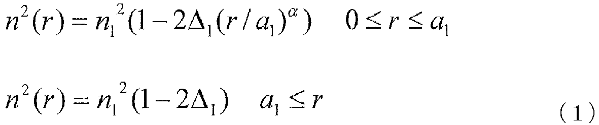
- the optical fiber according to the first or second aspect includes a core having an ⁇ th-power refractive-index distribution represented by Formula (1) and a clad provided on an outside of the core.
- n 2 r n 1 2 1 ⁇ 2 ⁇ 1 r / a 1 ⁇ 0 ⁇ r ⁇ a 1
- n 2 r n 1 2 1 ⁇ 2 ⁇ 1 a 1 ⁇ r
- n(r) denotes a refractive index at a position r in a radial direction from a center
- n 1 denotes a refractive index at a core center
- ⁇ denotes an index constant
- an optical fiber that can reduce a DMG generated in Raman amplification, even if a mode of pump light is a single mode, can be provided.
- a structure which includes the above optical fiber and performs Raman amplification using a propagation mode of pump light as one propagation mode in a mode group M is employed as an optical transmission system according to the present invention.
- a fourth aspect of the present invention relates to an optical transmission system, including the optical fiber according to any one aspect of the above first to third aspects, a mode converter which converts pump light to perform Raman amplification in the optical fiber into a single propagation mode included in the mode group M, and causes the converted pump light to enter the optical fiber, and a mode multiplexer which multiplexes signal light from two or more and Z or less transmitters, as mutually-different propagation modes, and couples the multiplexed signal light to one end of the optical fiber, at least two of the propagation modes of the signal light being propagation modes included in the mode group M.
- signal light of propagation modes in the mode group M is uniformly amplified by pump light of one propagation mode in the mode group M as one group, and a DMG can be reduced.
- a gain of the signal light and a gain of the group can be brought closer, and a DMG can be reduced.
- An optical transmission system that can reduce a DMG generated in Raman amplification, even if a mode of pump light is a single mode, can therefore be provided.
- a fifth aspect of the present invention relates to the optical transmission system according to the above fourth aspect, further including two or more and Z or less receivers, and a remote pump optical amplifier provided between the receivers and the transmitters and including the mode converter and a light source.
- an optical fiber and an optical transmission system that can reduce a DMG generated in Raman amplification, even if a mode of pump light is a single mode, can be provided.
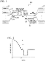
- FIG. 1 is a diagram illustrating an optical transmission system 301 of the present embodiment.
- the optical transmission system 301 includes an optical fiber 51 having a graded index (GI)-type core refractive index profile in which a propagation mode can propagate Z (Z is an integer of 2 or more) or more, a mode converter 52 which converts pump light to perform Raman amplification in the optical fiber 51, into one propagation mode included in a mode group M, and causes the converted pump light to enter the optical fiber 51, and a mode multiplexer 53 which multiplexes signal light from two or more and Z or less transmitters, as mutually-different propagation modes, and couples the multiplexed signal light to one end of the optical fiber 51, and at least two of the propagation modes of the signal light are propagation modes included in the mode group M.
- N-type signals transmitted from N transmitters 54 are multiplexed by the mode multiplexer 53.
- the multiplexed signal light is caused to enter the optical fiber 51, and is demultiplexed into Z ports by a mode demultiplexer 55 installed on an exit side.
- a refractive-index distribution of the optical fiber 51 that is used here, a refractive-index distribution in which at least a core portion has a GI-type shape is used.
- a pump light source 56 for distributed Raman amplification is included, and the pump light is caused to enter the optical fiber 51 after being converted into a desired mode as necessary by the mode converter 52.
- pump light In the optical transmission system 301, an example in which pump light enters from a receiver side. Alternatively, pump light can enter from a transmitter side.
- FIG. 2 is a diagram illustrating a refractive-index distribution of the optical fiber 51 included in the optical transmission system 301.
- the optical fiber 51 can obtain a similar effect by a refractive-index distribution other than the refractive-index distribution having a trench construction as illustrated in FIG. 2 .
- This structure is a GI-type structure that propagates a desired number of propagation modes, and is designed so that a group delay difference between modes becomes small.
- FIG. 2 includes a core having an ⁇ th-power refractive-index distribution represented by the following formula (1) and a clad on the outside of the core.
- n(r) denotes a refractive index at a position r in a radial direction from the center
- n 1 denotes a refractive index at the core center
- ⁇ denotes an index constant.
- the refractive-index distribution of the multi-mode optical fiber that is illustrated in FIG. 2 follows an ⁇ th-power refractive-index distribution in a region having a radius r smaller than a 1 .
- the index constant ⁇ is a dimensionless parameter indicating a grated-type profile, and is sometime called an alpha parameter.
- FIG. 1 is a dimensionless parameter indicating a grated-type profile, and is sometime called an alpha parameter.
- GI graded index
- Non-Patent Literature 1 a GI-shaped transmission path is used.
- these Non-Patent literatures discuss reducing a group delay difference between modes of a transmission path, and do not describe achieving a reduction in a propagation constant difference between propagation modes that is discussed in the present embodiment.
- FIG. 15 illustrates an effective area Aeff in a wavelength of 1550 nm of the signal light LP01, LP11, LP21, and LP02 modes that propagate in the optical fiber having the refractive-index distribution in FIG. 2 .
- FIG. 3 is a diagram illustrating a relationship between a propagation constant difference ⁇ 02-21 of the LP21 mode and the LP02 mode in a fiber having a step-shaped refractive-index distribution, and an optical fiber having the refractive-index distribution in FIG. 2 , and a wavelength.
- the step-shaped SI fiber being a comparative example has a core radius of 7 ⁇ m, and a specific refractive index difference of a core of 0.7%.
- a signal strength Sm of an mth mode can be represented by a propagation equation in the following formula (2).
- dS m dz ⁇ ⁇ s S m + ⁇ R ⁇ n f n , m P n ⁇ S m
- a pump light power P- of an nth mode that enters from a rear side (receiver side) of the optical fiber 51 can be represented by a propagation equation in the following formula (3).
- d P n ⁇ dz ⁇ ⁇ p P n ⁇ + ⁇ S ⁇ p ⁇ R ⁇ n f n , m S m P n ⁇
- ⁇ s and ⁇ p denote propagation losses of signal light and pump light
- ⁇ R denotes a Raman gain coefficient
- ⁇ s and ⁇ p denote wavelengths of signal light and pump light
- fn,m denotes a intensity overlap integral of signal light and pump light, and can be represented by the following formula (4).
- a gain of each propagation mode in multi-mode Raman amplification can be controlled by the fn,m.
- the fn,m varies by changing a propagation mode of incident pump light with respect to a propagation mode of signal light.
- FIG. 16 illustrates the size of fn,m that is obtainable when a mode of pump light is the LP01, LP11, LP21, or LP02 mode with respect to a propagation mode of signal light, in the optical fiber having the refractive-index distribution in FIG. 2 .
- a mode of pump light is the LP01, LP11, LP21, or LP02 mode with respect to a propagation mode of signal light, in the optical fiber having the refractive-index distribution in FIG. 2 .
- a wavelength of signal light is 1550 nm
- a wavelength of pump light is 1450 nm.
- an effect of coupling of the LP21 mode and the LP02 mode is not considered.
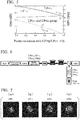
- FIG. 4 illustrates a calculation result obtained when a gain of each propagation mode and a pump ratio of pump modes are changed.
- a horizontal axis indicates a power ratio of the LP11 and LP21 modes included in pump light.
- a vertical axis indicates a gain of each propagation mode with respect to a strength ratio of pump light.
- FIG. 5 illustrates a calculation result obtained when a gain of each propagation mode and an power ratio of pump modes are changed
- a horizontal axis indicates a power ratio of the LP11 and LP21 modes included in pump light.
- a left vertical axis indicates a gain of each propagation mode with respect to a power ratio of pump light.
- a right vertical axis indicates DMGs of all propagation modes with respect to a power ratio of pump light.
- a DMG can be suppressed to 0.3 dB or less at the time of an on/off gain of 5 dB in excitation with pump light having a single mode, i.e., the LP21 mode (point with pump light ratio 1.0).
- the LP21 mode point with pump light ratio 1.0
- a gain of each propagation mode can be made equal at the point of pump light that has a pump light ratio 1.0 (in FIG. 4 , while a pump light ratio is set to 64:36, a pump light ratio is set to 100:0 in FIG. 5.).
- FIG. 5 illustrates a case where pump light has the LP21 mode, but the same applies to a case where pump light has the LP02 mode.
- FIG. 6 illustrates a measurement system of a distributed Raman gain.
- a Super luminescent diode (SLD) is used as a light source of signal light, and after polarization scrambling is performed for reducing polarization dependence, conversion to a ratio measurement mode is performed, and then, signal light is caused to enter a transmission path.
- the transmission path used for the measurement this time is a trench-type GI fiber as illustrated in FIG. 1 , and has a strip length of 71 km in total by vertically connecting fibers that can propagate six LP modes and four LP modes.
- An ⁇ -parameter of the connected GI fiber is in a range of 1.85-2.10.
- FIG. 7 illustrates a near field pattern entering the transmission path provided subsequently to a mode converter.
- a strength distribution of each of the LP01, LP11, LP21, and LP02 modes can be confirmed.
- pump light for distributed Raman amplification (wavelength of 1450 nm) has a configuration of entering from a subsequent stage of the transmission path, and a mode of pump light is caused to enter the transmission path after being converted into the LP01, LP11 or LP21 mode through a phase filter type mode converter after being emitted from a pump light source.
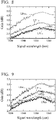
- FIG. 8 illustrates a result of a gain spectrum obtainable when pump light enters as the LP01 mode.
- adjustment of a pump light power is performed so that the maximum on/off gain of the LP01 mode becomes about 5 dB.
- the signal light LP01 mode obtains the largest gain
- the LP11 obtains a secondly-large gain.
- the LP21 and the LP02 modes obtain substantially similar gains. If the LP21 mode and the LP02 mode are not coupled, the LP02 mode is expected to obtain a larger gain than the LP21 mode as illustrated in FIG. 16 . Nevertheless, because the LP21 mode and the LP02 mode obtain substantially equal gains as illustrated in FIG. 8 , coupling of the LP21 mode and the LP02 mode as indicated in the calculation of FIG. 5 is considered to be generated in the transmission path used for the measurement.
- FIGS. 9 and 10 each illustrate a gain spectrum of each propagation mode that is obtainable when pump light is set to the LP11 mode or the LP21 mode. It can be confirmed that gains of the respective propagation modes come closer and DMGs becomes smaller, as pump light is set to LP01 in FIG. 8 , LP11 in FIG. 9 , and LP21 in FIG. 10 . In addition, similarly to the LP01 mode excitation, it can be confirmed that gains of the LP21 mode and the LP02 mode have similar values irrespective of a propagation mode of pump light.
- FIG. 11 illustrates a relationship between a propagation mode of pump light and a DMG of each propagation mode of signal light.
- a wavelength of signal light is 1550 nm. It was confirmed that a DMG (DMG of LP01 and LP21) that has been 1.9 dB when pump light is in the LP01 mode can be improved to a DMG (DMG of LP01 and LP02) of 0.8 dB when pump light is in the LP21 mode.
- the optical transmission system 301 of the present embodiment can reduce a DMG even if a propagation mode of pump light is one.
- FIG. 12 is a diagram illustrating an optical transmission system 302 of the present embodiment.
- the optical transmission system 302 includes a transmitter 54, the optical fiber 51, a pump light multiplexer 58, a receiver 57, and a remote pump optical amplifier.
- the remote pump optical amplifier includes the mode converter 52 and the light source 56.
- the optical fiber 51 is a GI-shaped optical fiber as illustrated in FIG. 2 , and is implemented by installing the remote pump optical amplifier at an intermediate portion of the transmitter 54 and the receiver 57.
- FIG. 12 illustrates an example in which pump light enters from the receiver 57 side.
- FIG. 14 illustrates a graph obtained by plotting a region of an ⁇ -parameter in which ⁇ becomes 1000 rad/m or less in the mode group with respect to M values.
Landscapes
- Physics & Mathematics (AREA)
- General Physics & Mathematics (AREA)
- Optics & Photonics (AREA)
- Engineering & Computer Science (AREA)
- Computer Networks & Wireless Communication (AREA)
- Signal Processing (AREA)
- Chemical & Material Sciences (AREA)
- Dispersion Chemistry (AREA)
- Electromagnetism (AREA)
- Optical Modulation, Optical Deflection, Nonlinear Optics, Optical Demodulation, Optical Logic Elements (AREA)
- Optical Communication System (AREA)
Abstract
Description
- The present invention relates to an optical fiber that enables Raman optical amplification in mode division multiplex transmission, and an optical transmission system including the same.
- Priority is claimed on Japanese Patent Application No.
2016-119474 filed on June 16, 2016 - Recently, due to the diversification of services, Internet traffic continues to increase. By increasing transmission speed or increasing the number of wavelength multiplexings by a wavelength division multiplexing (WDM) technique, to keep up with the above increase, transmission capacity of an optical fiber has dramatically increased. In addition, further expansion of transmission capacity is expected owing to a digital coherent technique. In a digital coherent transmission system, frequency usage efficiency is enhanced by using a multiple-value phase modulation signal, but a higher signal-to-noise ratio becomes necessary. Nevertheless, in a transmission system that uses a conventional single-mode fiber (SMF), transmission capacity is expected to be saturated at the boundary of 100 Tbit/sec due to an input power limit attributed to a nonlinear effect, in addition to a theoretical, and a further increase in capacity becomes difficult.
- In order to further increase transmission capacity in the future, a medium that realizes innovative expansion of transmission capacity is required. Thus, mode division multiplex transmission using a multi-mode fiber (MMF) that can achieve enhancement in space usage efficiency by using a plurality of propagation modes in an optical fiber has attracted attention. Previously, higher-order modes propagating in a fiber had been factors of signal deterioration, but active use of such modes is considered due to the development of digital signal processing, a multiplexing/demultiplex technique, and the like (e.g. refer to Non-Patent
Literature - Furthermore, in mode division multiplex transmission, a method that uses distributed Raman amplification to compensate for a signal-to-noise ratio of a transmission path, similarly to a single-mode transmission path, has been considered, and experiments and calculations have been performed (e.g. refer to Non-Patent
Literature - It is important to reduce a differential modal gain (DMG) in consideration of an optical amplification technique in mode division multiplex transmission. Nevertheless, signal light propagating in an MMF has a different electric field distribution for each mode, and because the size of an overlap of an electric field distribution of signal light and an electric field distribution of pump light differs for each mode, a DMG is generated.
- For example, it has been reported that, by setting a propagation mode of pump light to an LP11 mode in a transmission path that uses three-mode distributed Raman amplification, DMG can be reduced, and transmission exceeding 1000 km is possible (e.g. refer to Non-Patent
Literature 2.). - In addition, Raman amplification that uses a transmission path (Step-Index (SI)-types fiber) having a step-shaped refractive-index distribution has been considered, and it has been reported that, by setting propagation modes of pump light to an LP21 mode and an LP02 mode, and setting a power ratio therebetween to 7:3, a DMG can be reduced up to 0.13 dB (e.g. refer to Non-Patent
Literature 3.). -
- [Non-Patent Document 1]
R. Ryf, A. Sierra, R.-J. Essiambre, and S. Randel, A. H. Gnauck, C. Bolle, M. Esmaeelpour, P. J. Winzer, R. Delbue, P. Pupalaikise, A. Sureka, D. W. Peckham, A. McCurdy, and R. Lingle, Jr., "Mode-Equalized Distributed Raman Amplification in 137-km Few-Mode Fiber", ECOC, paper Th.13.K.5. 2011. - [Non-Patent Document 2]
R. Ryf, M. Esmaeelpour, N.K. Fontaine, H. Chen, A.H. Gnauck, R.-J. Essiambre, J. Toulouse, Y. Sun, and R. Lingle, Jr., "Distributed Raman Amplification based Transmission over 1050-km Few-Mode Fiber", ECOC, Tu.3.2.3, 2015. - [Non-Patent Document 3]
R. Ryf, R.-J. Essiambre, J. Hoyningen-Huene, and P. J. Winzer, "Analysis of Mode-Dependent Gain in Raman Amplified Few-Mode Fiber", in Optical Fiber Communication Conference, OSA Technical Digest, paper OW1D.2. 2012. - [Non-Patent Document 4]
T. Mori, T. Sakamoto, M. Wada, T. Yamamoto, and F. Yamamoto, "Few-mode Fibers Supporting More Than Two LP Modes For Mode-Division-Multiplexed Transmission With MIMO DSP", J. Lightw. Technol., vol. 32, No. 14, pp. 2468-2479, 2014. - [Non-Patent Document 5]
T. Mori, T. Sakamoto, M. Wada, T. Yamamoto, and K. Nakajima, "Strongly-coupled Two-LP-mode Ring-core Fiber with Optimized Index Profile Considering S-bend Model", OFC., W1F. 6, 2016. - When the number of modes of a signal to be transmitted increases, accurate control of a mode ratio of pump light becomes necessary to reduce DMG. In this case, a device that accurately controls a mode ratio is required, which complicates device structure and increases cost. Thus, to solve the above problem, the present invention provides an optical fiber and an optical transmission system that can reduce DMG generated in Raman amplification, even if a mode of pump light is a single mode.
- In order to achieve the above object, a structure that reduces a propagation constant difference between propagation modes included in a desired mode group is employed as an optical fiber according to the present invention.
- A first aspect of the present invention relates to an optical fiber having a graded index (GI)-type core refractive index profile in which a propagation mode can propagate Z (Z is an integer of 2 or more) or more, and an α-parameter having a value in which a propagation constant mutual difference is 1000 rad/m or less in a propagation mode group of a mode group M (M is M = 2p + I - 1 and 3 or more when a propagation mode is denoted by LPIp.).
- In a second aspect of the present invention, the optical fiber according to the above first aspect preferably has a value α of the α-parameter that satisfies 1.67 - 0.31exp(-(M-3)/1.80) ≤ α ≤ 2.37 + 0.63exp(-(M-3)/1.25).
- The α-parameter can be set for each mode group M in which a propagation constant difference is desired to be reduced.
- By setting an α-parameter of a GI fiber to the above value, a propagation constant difference between propagation modes included in the mode group M is reduced in the GI fiber, and coupling is generated between the propagation modes. Thus, Raman amplification of pump light of one propagation mode included in the mode group M can be performed using the coupled propagation modes as one group, and a DMG can be reduced. An optical fiber that can reduce a DMG generated in Raman amplification, even if a mode of pump light is a single mode, can therefore be provided.
- In a third aspect of the present invention, the optical fiber according to the first or second aspect includes a core having an αth-power refractive-index distribution represented by Formula (1) and a clad provided on an outside of the core.

- In formula (1), n(r) denotes a refractive index at a position r in a radial direction from a center, n1 denotes a refractive index at a core center, and α denotes an index constant.
- Also in the above configuration, an optical fiber that can reduce a DMG generated in Raman amplification, even if a mode of pump light is a single mode, can be provided.
- In addition, a structure which includes the above optical fiber and performs Raman amplification using a propagation mode of pump light as one propagation mode in a mode group M is employed as an optical transmission system according to the present invention.
- A fourth aspect of the present invention relates to an optical transmission system, including the optical fiber according to any one aspect of the above first to third aspects, a mode converter which converts pump light to perform Raman amplification in the optical fiber into a single propagation mode included in the mode group M, and causes the converted pump light to enter the optical fiber, and a mode multiplexer which multiplexes signal light from two or more and Z or less transmitters, as mutually-different propagation modes, and couples the multiplexed signal light to one end of the optical fiber, at least two of the propagation modes of the signal light being propagation modes included in the mode group M.
- As described above, signal light of propagation modes in the mode group M is uniformly amplified by pump light of one propagation mode in the mode group M as one group, and a DMG can be reduced. In addition, even if there exists signal light of a propagation mode not included in the mode group M, a gain of the signal light and a gain of the group can be brought closer, and a DMG can be reduced. An optical transmission system that can reduce a DMG generated in Raman amplification, even if a mode of pump light is a single mode, can therefore be provided.
- A fifth aspect of the present invention relates to the optical transmission system according to the above fourth aspect, further including two or more and Z or less receivers, and a remote pump optical amplifier provided between the receivers and the transmitters and including the mode converter and a light source.
- According to the above configuration, by combining with the remote pump optical amplification technique, further elongation of the optical transmission system can be realized.
- According to the above aspects of the present invention, an optical fiber and an optical transmission system that can reduce a DMG generated in Raman amplification, even if a mode of pump light is a single mode, can be provided.
-
-
FIG. 1 is a diagram illustrating a Raman transmission system according to the present invention. -
FIG. 2 is a diagram illustrating a refractive-index distribution of an optical fiber according to the present invention. -
FIG. 3 is a diagram illustrating a relationship between a propagation constant difference Δβ02-21 of an LP21 mode and an LP02 mode in a step-type fiber and a graded index fiber, and a wavelength. -
FIG. 4 is a diagram illustrating a relationship between a DMG obtainable when it is supposed that there is no intermode coupling during the propagation in a transmission path, and a ratio of modes included in pump light (LP11 mode and LP21 mode). -
FIG. 5 is a diagram illustrating a relationship between a DMG obtainable when it is supposed that there is intermode coupling during the propagation in a transmission path, and a ratio of modes included in pump light (LP11 mode group and LP21 mode). -
FIG. 6 is a diagram illustrating a measurement system of a distributed Raman gain. -
FIG. 7 is a diagram illustrating a near field pattern of each propagation mode that is obtained after mode conversion. -
FIG. 8 is a diagram illustrating a gain spectrum of each propagation mode that is obtainable when pump light enters as an LP01 mode. -
FIG. 9 is a diagram illustrating a gain spectrum of each propagation mode that is obtainable when pump light enters as the LP11 mode. -
FIG. 10 is a diagram illustrating a gain spectrum of each propagation mode that is obtainable when pump light enters as the LP21 mode. -
FIG. 11 is a diagram illustrating a relationship between a pump mode and a DMG in a signal light wavelength of 1550 nm. -
FIG. 12 is a diagram illustrating a structure in which a remote pump amplification technique is applied in an optical transmission system according to the present invention. -
FIG. 13 is a diagram illustrating a relationship between a Δβ and an α-parameter of a GI fiber in the optical fiber according to the present invention. -
FIG. 14 is a diagram illustrating a relationship between an M value and an α value in which Δβ becomes 1000 or less in a mode group, in the optical fiber according to the present invention. -
FIG. 15 is a diagram illustrating an effective cross-sectional area Aeff in a wavelength of 1550 nm of signal light LP01, LP11, LP21, and LP02 modes in the optical fiber according to the present invention. -
FIG. 16 is a diagram illustrating, for each mode, a size fn,m of an overlap of signal light and pump light in the optical fiber according to the present invention. - Embodiments of the present invention will be described below with reference to the appended drawings. The embodiments below are not limited. In this specification and the drawings, components with the same reference number are assumed to indicate mutually the same components.
-
FIG. 1 is a diagram illustrating anoptical transmission system 301 of the present embodiment. Theoptical transmission system 301 includes anoptical fiber 51 having a graded index (GI)-type core refractive index profile in which a propagation mode can propagate Z (Z is an integer of 2 or more) or more, amode converter 52 which converts pump light to perform Raman amplification in theoptical fiber 51, into one propagation mode included in a mode group M, and causes the converted pump light to enter theoptical fiber 51, and amode multiplexer 53 which multiplexes signal light from two or more and Z or less transmitters, as mutually-different propagation modes, and couples the multiplexed signal light to one end of theoptical fiber 51, and at least two of the propagation modes of the signal light are propagation modes included in the mode group M. Here, the mode group M is a group of propagation modes that satisfy M = 2p+ I - 1 and 3 or more when a propagation mode is denoted by LPIp. - N-type signals transmitted from
N transmitters 54 are multiplexed by themode multiplexer 53. The multiplexed signal light is caused to enter theoptical fiber 51, and is demultiplexed into Z ports by amode demultiplexer 55 installed on an exit side. As a refractive-index distribution of theoptical fiber 51 that is used here, a refractive-index distribution in which at least a core portion has a GI-type shape is used. In addition, a pumplight source 56 for distributed Raman amplification is included, and the pump light is caused to enter theoptical fiber 51 after being converted into a desired mode as necessary by themode converter 52. In theoptical transmission system 301, an example in which pump light enters from a receiver side. Alternatively, pump light can enter from a transmitter side. -
FIG. 2 is a diagram illustrating a refractive-index distribution of theoptical fiber 51 included in theoptical transmission system 301. In the refractive-index distribution inFIG. 2 , calculation of a Raman gain to be described later is performed. In addition, theoptical fiber 51 can obtain a similar effect by a refractive-index distribution other than the refractive-index distribution having a trench construction as illustrated inFIG. 2 . This structure is a GI-type structure that propagates a desired number of propagation modes, and is designed so that a group delay difference between modes becomes small. -
FIG. 2 includes a core having an αth-power refractive-index distribution represented by the following formula (1) and a clad on the outside of the core. Here, n(r) denotes a refractive index at a position r in a radial direction from the center, n1 denotes a refractive index at the core center, and α denotes an index constant. The refractive-index distribution of the multi-mode optical fiber that is illustrated inFIG. 2 follows an αth-power refractive-index distribution in a region having a radius r smaller than a1. In addition, the index constant α is a dimensionless parameter indicating a grated-type profile, and is sometime called an alpha parameter. In addition,FIG. 2 includes a trench portion with a reduced refractive index, in a clad region, for restricting the number of propagation modes. The details of the design are reported inNon-Patent Literature 4.
- As the optical fiber having the refractive-index distribution in
FIG. 2 , not only a group delay difference between modes becomes small, but also propagation constants become very close in mode groups in which the mode groups M (M is a mode group including LPIp modes satisfying M = 2p + I - 1) are three or more, and strong coupling is easily generated in the groups. Generally, it is known that, if a propagation constant difference between modes is 1000 or less, mode coupling is generated by an effect of bending or torsion of a transmission path, or the like (e.g. refer to Non-Patent Literature 5). - In other words, the
optical fiber 51 is an optical fiber having a graded index (GI)-type core refractive index profile in which a propagation mode can propagate Z (Z is an integer of 2 or more) or more, and an α-parameter is a value in which a propagation constant mutual difference is 1000 rad/m or less in a propagation mode group of the mode group M (M is M = 2p + I - 1 and 3 or more when a propagation mode is denoted by LPIp). - In addition, also in the consideration of
Non-Patent Literature 1 andNon-Patent Literature 2, a GI-shaped transmission path is used. Nevertheless, these Non-Patent literatures discuss reducing a group delay difference between modes of a transmission path, and do not describe achieving a reduction in a propagation constant difference between propagation modes that is discussed in the present embodiment. - Here, as an example, the description will be given using an optical fiber that can propagate signal light LP01, LP11, LP21, and LP02 modes.
FIG. 15 illustrates an effective area Aeff in a wavelength of 1550 nm of the signal light LP01, LP11, LP21, and LP02 modes that propagate in the optical fiber having the refractive-index distribution inFIG. 2 . -
FIG. 3 is a diagram illustrating a relationship between a propagation constant difference Δβ02-21 of the LP21 mode and the LP02 mode in a fiber having a step-shaped refractive-index distribution, and an optical fiber having the refractive-index distribution inFIG. 2 , and a wavelength. The step-shaped SI fiber being a comparative example has a core radius of 7 µm, and a specific refractive index difference of a core of 0.7%. - By the result of calculation, it can be confirmed that, in the SI fiber, about 2500 rad/m of Δβ02-21 is generated in all bands in which calculation has been performed. On the other hand, in the GI fiber having the refractive-index distribution in
FIG. 2 , Δβ02-21 becomes small to about 50 rad/m, and the LP21 mode and the LP02 mode can be expected to sufficiently coupled during transmission. - Next, calculation of a gain in distributed Raman amplification that uses an optical fiber having the refractive-index distribution in
FIG. 2 is performed. The calculation of a Raman gain generated for each mode is performed in the following manner. - A signal strength Sm of an mth mode can be represented by a propagation equation in the following formula (2).

- A pump light power P- of an nth mode that enters from a rear side (receiver side) of the
optical fiber 51 can be represented by a propagation equation in the following formula (3). In addition, the same applies to a case where pump light is caused to enter from a front side (transmitter side) of theoptical fiber 51.
- Here, αs and αp denote propagation losses of signal light and pump light, γR denotes a Raman gain coefficient, and λs and λp denote wavelengths of signal light and pump light. In addition, fn,m denotes a intensity overlap integral of signal light and pump light, and can be represented by the following formula (4).

- It can be confirmed by the above-described formulae that a gain of each propagation mode in multi-mode Raman amplification can be controlled by the fn,m. The fn,m varies by changing a propagation mode of incident pump light with respect to a propagation mode of signal light.
-
FIG. 16 illustrates the size of fn,m that is obtainable when a mode of pump light is the LP01, LP11, LP21, or LP02 mode with respect to a propagation mode of signal light, in the optical fiber having the refractive-index distribution inFIG. 2 . Here, calculation has been performed assuming that a wavelength of signal light is 1550 nm, and a wavelength of pump light is 1450 nm. In addition, here, an effect of coupling of the LP21 mode and the LP02 mode is not considered. - From Table in
FIG. 16 , it can be confirmed that, when coupling between modes that propagate in the optical fiber is sufficiently small (in the case of SI fiber), if a pump light mode is a single mode, a intensity overlap integral with a pump light distribution differs depending on a mode of signal light. In addition, "sufficiently small coupling" means that a propagation constant difference β is 1000 rad/m or more, as described inFIG. 3 . - First of all, it is supposed that there is no coupling between modes in the transmission path in the SI fiber, and calculation of a Raman gain is performed.
FIG. 4 illustrates a calculation result obtained when a gain of each propagation mode and a pump ratio of pump modes are changed. A horizontal axis indicates a power ratio of the LP11 and LP21 modes included in pump light. A vertical axis indicates a gain of each propagation mode with respect to a strength ratio of pump light. Referring toFIG. 3 , for minimizing a gain difference between four LP modes, it is necessary to set a power ratio of pump light of the LP21 mode and the LP02 mode (pump light ratio, LP21:LP02) to 64:36, and cause the pump light to enter a transmission path. - Next, calculation of a Raman gain that is obtainable when it is supposed that coupling of the LP21 mode and the LP02 mode is generated in the transmission path in the GI fiber (Δβ02-21 is sufficiently small) is performed.
FIG. 5 illustrates a calculation result obtained when a gain of each propagation mode and an power ratio of pump modes are changed A horizontal axis indicates a power ratio of the LP11 and LP21 modes included in pump light. A left vertical axis indicates a gain of each propagation mode with respect to a power ratio of pump light. A right vertical axis indicates DMGs of all propagation modes with respect to a power ratio of pump light. In the calculation of the GI fiber, gains of the LP21 mode and the LP02 mode are calculated as one group, and the result becomes equal to a result obtained when the LP21 mode and the LP02 mode propagate with equal strength. - It can be confirmed from
FIG. 5 that a DMG can be suppressed to 0.3 dB or less at the time of an on/off gain of 5 dB in excitation with pump light having a single mode, i.e., the LP21 mode (point with pump light ratio 1.0). In other words, by promoting coupling of the LP21 mode and the LP02 mode using a GI fiber having a sufficiently-small Δβ02-21, a gain of each propagation mode (the LP21 mode and the LP02 mode are one group) can be made equal at the point of pump light that has a pump light ratio 1.0 (inFIG. 4 , while a pump light ratio is set to 64:36, a pump light ratio is set to 100:0 inFIG. 5.). FIG. 5 illustrates a case where pump light has the LP21 mode, but the same applies to a case where pump light has the LP02 mode. - Next, whether a DMG can be reduced is experimentally checked.
FIG. 6 illustrates a measurement system of a distributed Raman gain. A Super luminescent diode (SLD) is used as a light source of signal light, and after polarization scrambling is performed for reducing polarization dependence, conversion to a ratio measurement mode is performed, and then, signal light is caused to enter a transmission path. The transmission path used for the measurement this time is a trench-type GI fiber as illustrated inFIG. 1 , and has a strip length of 71 km in total by vertically connecting fibers that can propagate six LP modes and four LP modes. An α-parameter of the connected GI fiber is in a range of 1.85-2.10. - Also,
FIG. 7 illustrates a near field pattern entering the transmission path provided subsequently to a mode converter. A strength distribution of each of the LP01, LP11, LP21, and LP02 modes can be confirmed. In addition, pump light for distributed Raman amplification (wavelength of 1450 nm) has a configuration of entering from a subsequent stage of the transmission path, and a mode of pump light is caused to enter the transmission path after being converted into the LP01, LP11 or LP21 mode through a phase filter type mode converter after being emitted from a pump light source. -
FIG. 8 illustrates a result of a gain spectrum obtainable when pump light enters as the LP01 mode. In this experiment, adjustment of a pump light power is performed so that the maximum on/off gain of the LP01 mode becomes about 5 dB. As can be confirmed from the calculation, the signal light LP01 mode obtains the largest gain, and the LP11 obtains a secondly-large gain. On the other hand, the LP21 and the LP02 modes obtain substantially similar gains. If the LP21 mode and the LP02 mode are not coupled, the LP02 mode is expected to obtain a larger gain than the LP21 mode as illustrated inFIG. 16 . Nevertheless, because the LP21 mode and the LP02 mode obtain substantially equal gains as illustrated inFIG. 8 , coupling of the LP21 mode and the LP02 mode as indicated in the calculation ofFIG. 5 is considered to be generated in the transmission path used for the measurement. -
FIGS. 9 and10 each illustrate a gain spectrum of each propagation mode that is obtainable when pump light is set to the LP11 mode or the LP21 mode. It can be confirmed that gains of the respective propagation modes come closer and DMGs becomes smaller, as pump light is set to LP01 inFIG. 8 , LP11 inFIG. 9 , and LP21 inFIG. 10 . In addition, similarly to the LP01 mode excitation, it can be confirmed that gains of the LP21 mode and the LP02 mode have similar values irrespective of a propagation mode of pump light. -
FIG. 11 illustrates a relationship between a propagation mode of pump light and a DMG of each propagation mode of signal light. A wavelength of signal light is 1550 nm. It was confirmed that a DMG (DMG of LP01 and LP21) that has been 1.9 dB when pump light is in the LP01 mode can be improved to a DMG (DMG of LP01 and LP02) of 0.8 dB when pump light is in the LP21 mode. - In the present embodiment, to solve the problem, a GI fiber (a propagation mode can propagate Z (Z is an integer of 2 or more) or more) that has an α-parameter being a value in which a propagation constant mutual difference is 1000 rad/m or less in a propagation mode group of the mode group M (M is M = 2p + I - 1 and 3 or more when a propagation mode is denoted by LPIp.) is used as an optical fiber for Raman amplification. By using such an optical fiber, coupling of signal light of propagation modes included in the mode group M is promoted. Thus, signal light of propagation modes included in the mode group M can obtain gains as one mode group at the time of Raman amplification. Furthermore, if coupling of signal light of propagation modes is promoted, a pump light ratio at a point at which a gain of the mode group and a gain of another propagation mode not included in the mode group M become equal at the time of Raman amplification becomes 1.0 or 0.0 (propagation mode of pump light is one). Thus, the
optical transmission system 301 of the present embodiment can reduce a DMG even if a propagation mode of pump light is one. In addition, it is preferable to use pump light of one propagation mode in the mode group M, as pump light. - The present embodiment relates to an optical transmission system combined with a remote pump optical amplification technique for elongating an optical transmission system.
FIG. 12 is a diagram illustrating anoptical transmission system 302 of the present embodiment. Theoptical transmission system 302 includes atransmitter 54, theoptical fiber 51, apump light multiplexer 58, areceiver 57, and a remote pump optical amplifier. The remote pump optical amplifier includes themode converter 52 and thelight source 56. - The
optical fiber 51 is a GI-shaped optical fiber as illustrated inFIG. 2 , and is implemented by installing the remote pump optical amplifier at an intermediate portion of thetransmitter 54 and thereceiver 57. As a mode of pump light entering theoptical fiber 51, one mode is selectively used from among a group in which mode groups M (M is a mode group including an LPIp mode that satisfies M = 2p + I - 1) that propagate in theoptical fiber 51 are three or more.FIG. 12 illustrates an example in which pump light enters from thereceiver 57 side. By combining with the remote pump optical amplification technique in this manner, further elongation can be realized. - In the present embodiment, an α-parameter in a case where mode groups exceed three will be described.
FIG. 13 illustrates a result obtained by performing calculation for a relationship between Δβ of mode groups M being three or more, and an α-parameter of a GI fiber. This indicates results of Δβ between the LP21 and the LP02 modes for M = 3, between the LP31 and the LP12 modes for M = 4, between the LP41 and the LP03 modes having the largest Δβ for M = 5, and between the LP14 and the LP71 modes for M = 8. - Next,
FIG. 14 illustrates a graph obtained by plotting a region of an α-parameter in which Δβ becomes 1000 rad/m or less in the mode group with respect to M values. When fitting is performed on the calculation result, by using a region of an α-parameter in which 1.67 - 0.31exp(-(M-3)/1.80) ≤ α ≤ 2.37 + 0.63exp(-(M-3)/1.25) is satisfied, coupling in the mode group M can be promoted, and a DMG can be reduced. - The embodiments of the present invention are not limited to the above and are merely examples. The present invention can be implemented in forms in which various modifications and improvements are performed based on the knowledge of one skilled in the art.
-
- 51: Optical fiber
- 52: Mode converter
- 53: Mode multiplexer
- 54: Transmitter
- 55: Mode demultiplexer
- 56: Light source
- 57: Receiver
- 58: Pump light multiplexer
- 301, 302: Optical transmission system
Claims (5)
- An optical fiber having a graded index (GI)-type core refractive index profile in which a propagation mode can propagate Z (Z is an integer of 2 or more) or more,
wherein an α-parameter is a value in which a propagation constant mutual difference is 1000 rad/m or less in a propagation mode group of a mode group M (M is M = 2p + I - 1 and 3 or more when a propagation mode is denoted by LPIp). - The optical fiber according to Claim 1, wherein a value α of the α-parameter satisfies 1.67 - 0.31exp(-(M-3)/1.80) ≤ α ≤ 2.37 + 0.63exp(-(M-3)/1.25).
- The optical fiber according to Claim 1 or 2, comprising a core having an αth-power refractive-index distribution represented by Formula (1) and a clad provided on an outside of the core.
- An optical transmission system, comprising:the optical fiber according to any one of Claims 1 to 3;a mode converter which converts pump light to perform Raman amplification in the optical fiber into a single propagation mode included in the mode group M, and causes the converted pump light to enter the optical fiber, and a mode multiplexer which multiplexes signal light from two or more and Z or less transmitters, as mutually-different propagation modes, and couples the multiplexed signal light to one end of the optical fiber, at least two of the propagation modes of the signal light being propagation modes included in the mode group M.
- The optical transmission system according to Claim 4, further comprising:two or more and Z or less receivers; anda remote pump optical amplifier provided between the receivers and the transmitters and including the mode converter and a light source.
Applications Claiming Priority (2)
| Application Number | Priority Date | Filing Date | Title |
|---|---|---|---|
| JP2016119474 | 2016-06-16 | ||
| PCT/JP2017/021483 WO2017217334A1 (en) | 2016-06-16 | 2017-06-09 | Optical fiber and optical transmission system |
Publications (3)
| Publication Number | Publication Date |
|---|---|
| EP3457186A1 true EP3457186A1 (en) | 2019-03-20 |
| EP3457186A4 EP3457186A4 (en) | 2020-01-22 |
| EP3457186B1 EP3457186B1 (en) | 2022-10-26 |
Family
ID=60663508
Family Applications (1)
| Application Number | Title | Priority Date | Filing Date |
|---|---|---|---|
| EP17813231.2A Active EP3457186B1 (en) | 2016-06-16 | 2017-06-09 | An optical transmission system |
Country Status (5)
| Country | Link |
|---|---|
| US (1) | US20200192022A1 (en) |
| EP (1) | EP3457186B1 (en) |
| JP (1) | JP6734374B2 (en) |
| CN (1) | CN109313307B (en) |
| WO (1) | WO2017217334A1 (en) |
Families Citing this family (5)
| Publication number | Priority date | Publication date | Assignee | Title |
|---|---|---|---|---|
| JP7006537B2 (en) * | 2018-08-16 | 2022-02-10 | 日本電信電話株式会社 | Raman gain efficiency distribution test method and Raman gain efficiency distribution test equipment |
| CN109149339B (en) * | 2018-08-30 | 2020-06-30 | 中国人民解放军国防科技大学 | A high-brightness fiber laser in the 800 nm band that can be used to pump thulium-doped fibers |
| JP7040390B2 (en) * | 2018-10-02 | 2022-03-23 | 日本電信電話株式会社 | Backscattered light amplification device, optical pulse test device, backscattered light amplification method, and light pulse test method |
| JP7270913B2 (en) * | 2020-02-27 | 2023-05-11 | 日本電信電話株式会社 | Method and apparatus for evaluating mode group delay characteristics of optical fiber |
| US20230170993A1 (en) * | 2021-11-30 | 2023-06-01 | Mario Zitelli | Mode-division multiplexed fiber raman amplifier system and method |
Family Cites Families (26)
| Publication number | Priority date | Publication date | Assignee | Title |
|---|---|---|---|---|
| US3904268A (en) * | 1974-11-15 | 1975-09-09 | Corning Glass Works | Optical waveguide having optimal index gradient |
| US4057320A (en) * | 1976-07-26 | 1977-11-08 | Bell Telephone Laboratories, Incorporated | Optical fiber waveguide having minimum modal dispersion |
| JPS58115403A (en) * | 1981-12-28 | 1983-07-09 | Fujikura Ltd | Multicore constant polarization optical fiber and its manufacture |
| JPS58156830A (en) * | 1982-03-15 | 1983-09-17 | Nippon Telegr & Teleph Corp <Ntt> | Method and device for measuring difference in propagation constant of optical fiber |
| JPS62223721A (en) * | 1986-03-26 | 1987-10-01 | Mitsubishi Electric Corp | Canceling device for polarization of optical fiber |
| US5295211A (en) * | 1993-01-07 | 1994-03-15 | Corning Incorporated | Fiber amplifier coupler |
| JP3482348B2 (en) * | 1998-11-12 | 2003-12-22 | 日本電信電話株式会社 | Remote pump light transmission system |
| CA2372638C (en) * | 2001-02-21 | 2006-09-12 | Nippon Telegraph And Telephone Corporation | Thulium-doped fiber amplifier using pump light for improving conversion efficiency in s-band |
| US20020118934A1 (en) * | 2001-02-23 | 2002-08-29 | Yochay Danziger | Method and system for dispersion management with Raman amplification |
| WO2003034118A1 (en) * | 2001-10-17 | 2003-04-24 | Risø National Laboratory | A system for electromagnetic field conversion |
| JP2005010777A (en) * | 2003-06-19 | 2005-01-13 | Furukawa Electric Co Ltd:The | Optical fiber, optical fiber module, and Raman amplifier |
| JP2005101516A (en) * | 2003-09-03 | 2005-04-14 | Nippon Telegr & Teleph Corp <Ntt> | Optical fiber communication system, pumping light source device, and optical communication method |
| CN100337155C (en) * | 2004-09-15 | 2007-09-12 | 华为技术有限公司 | Light transmission system and light amplifying method used therein |
| JP2007005484A (en) * | 2005-06-22 | 2007-01-11 | Fujitsu Ltd | Optical amplifier and optical fiber |
| JP5014640B2 (en) * | 2006-02-15 | 2012-08-29 | 株式会社フジクラ | Multimode fiber, optical amplifier and fiber laser |
| US9481599B2 (en) * | 2010-12-21 | 2016-11-01 | Corning Incorporated | Method of making a multimode optical fiber |
| JP2012194362A (en) * | 2011-03-16 | 2012-10-11 | Nippon Telegr & Teleph Corp <Ntt> | Mode multi/demultiplexing coupler and manufacturing method thereof |
| US9759860B2 (en) * | 2012-03-05 | 2017-09-12 | Alcatel Lucent | Multimode optical fiber, mode delay adjuster for fiber systems, and methods to use such fibers, adjusters, and systems |
| US20130243382A1 (en) * | 2012-03-13 | 2013-09-19 | Ming-Jun Li | Gradient-index multimode optical fibers for optical fiber connectors |
| US9124066B2 (en) * | 2012-05-02 | 2015-09-01 | Lawrence Livermore National Security, Llc | Diffractive optical elements for transformation of modes in lasers |
| JP6059560B2 (en) * | 2013-03-04 | 2017-01-11 | 日本電信電話株式会社 | Multimode transmission optical amplifier |
| JP6092029B2 (en) * | 2013-07-17 | 2017-03-08 | 日本電信電話株式会社 | Multimode optical fiber and optical fiber transmission system |
| US9537282B2 (en) * | 2013-09-20 | 2017-01-03 | Alcatel Lucent | System and method for a multi-mode pump in an optical amplifier |
| JP6339401B2 (en) * | 2014-03-31 | 2018-06-06 | Kddi株式会社 | Mode multiplexing transmission optical transmitter and optical communication system |
| JP2015212757A (en) * | 2014-05-02 | 2015-11-26 | 日本電信電話株式会社 | Multi-mode optical fiber and design method of multi-mode optical fiber |
| US9599460B2 (en) * | 2014-10-16 | 2017-03-21 | Nec Corporation | Hybrid Raman and Brillouin scattering in few-mode fibers |
-
2017
- 2017-06-09 WO PCT/JP2017/021483 patent/WO2017217334A1/en not_active Ceased
- 2017-06-09 EP EP17813231.2A patent/EP3457186B1/en active Active
- 2017-06-09 US US16/309,527 patent/US20200192022A1/en not_active Abandoned
- 2017-06-09 CN CN201780036902.2A patent/CN109313307B/en active Active
- 2017-06-09 JP JP2018523871A patent/JP6734374B2/en active Active
Also Published As
| Publication number | Publication date |
|---|---|
| JP6734374B2 (en) | 2020-08-05 |
| CN109313307B (en) | 2020-12-01 |
| EP3457186A4 (en) | 2020-01-22 |
| EP3457186B1 (en) | 2022-10-26 |
| WO2017217334A1 (en) | 2017-12-21 |
| CN109313307A (en) | 2019-02-05 |
| JPWO2017217334A1 (en) | 2018-10-18 |
| US20200192022A1 (en) | 2020-06-18 |
Similar Documents
| Publication | Publication Date | Title |
|---|---|---|
| US8655133B2 (en) | Optical fiber and optical communication system including same | |
| EP3457186B1 (en) | An optical transmission system | |
| EP3495859B1 (en) | Inter-mode loss difference compensator and optical amplifier | |
| EP3460542B1 (en) | Method of designing an optical fiber | |
| US20210234326A1 (en) | Intermode loss difference compensation fiber, optical amplifier, and transmission path design method | |
| JP5059797B2 (en) | Optical fiber, optical fiber design method, and optical wavelength division multiplexing communication system | |
| US11156767B2 (en) | Optical fiber and optical transmission system | |
| JP2008224969A (en) | Optical fiber and optical fiber transmission line | |
| JP5079664B2 (en) | Optical wavelength division multiplexing communication system, exciter and mode filter | |
| US11888281B2 (en) | Multimode optical amplifier | |
| JP6824814B2 (en) | Loss difference compensator | |
| JP6092029B2 (en) | Multimode optical fiber and optical fiber transmission system | |
| JP6654064B2 (en) | Mode converter, optical amplifier and optical transmission system | |
| EP3514895A1 (en) | Optical amplifier | |
| JP2019036880A (en) | Optical transmission line and optical transmission system | |
| JP2006038898A (en) | Single mode optical fiber and distributed Raman amplification transmission system |
Legal Events
| Date | Code | Title | Description |
|---|---|---|---|
| STAA | Information on the status of an ep patent application or granted ep patent |
Free format text: STATUS: THE INTERNATIONAL PUBLICATION HAS BEEN MADE |
|
| PUAI | Public reference made under article 153(3) epc to a published international application that has entered the european phase |
Free format text: ORIGINAL CODE: 0009012 |
|
| STAA | Information on the status of an ep patent application or granted ep patent |
Free format text: STATUS: REQUEST FOR EXAMINATION WAS MADE |
|
| 17P | Request for examination filed |
Effective date: 20181213 |
|
| AK | Designated contracting states |
Kind code of ref document: A1 Designated state(s): AL AT BE BG CH CY CZ DE DK EE ES FI FR GB GR HR HU IE IS IT LI LT LU LV MC MK MT NL NO PL PT RO RS SE SI SK SM TR |
|
| AX | Request for extension of the european patent |
Extension state: BA ME |
|
| DAV | Request for validation of the european patent (deleted) | ||
| DAX | Request for extension of the european patent (deleted) | ||
| A4 | Supplementary search report drawn up and despatched |
Effective date: 20200103 |
|
| RIC1 | Information provided on ipc code assigned before grant |
Ipc: G02B 6/028 20060101AFI20191218BHEP Ipc: H04J 14/04 20060101ALI20191218BHEP Ipc: H04B 10/291 20130101ALI20191218BHEP Ipc: G02B 6/036 20060101ALI20191218BHEP |
|
| STAA | Information on the status of an ep patent application or granted ep patent |
Free format text: STATUS: EXAMINATION IS IN PROGRESS |
|
| 17Q | First examination report despatched |
Effective date: 20200916 |
|
| GRAP | Despatch of communication of intention to grant a patent |
Free format text: ORIGINAL CODE: EPIDOSNIGR1 |
|
| STAA | Information on the status of an ep patent application or granted ep patent |
Free format text: STATUS: GRANT OF PATENT IS INTENDED |
|
| INTG | Intention to grant announced |
Effective date: 20220525 |
|
| GRAS | Grant fee paid |
Free format text: ORIGINAL CODE: EPIDOSNIGR3 |
|
| GRAA | (expected) grant |
Free format text: ORIGINAL CODE: 0009210 |
|
| STAA | Information on the status of an ep patent application or granted ep patent |
Free format text: STATUS: THE PATENT HAS BEEN GRANTED |
|
| AK | Designated contracting states |
Kind code of ref document: B1 Designated state(s): AL AT BE BG CH CY CZ DE DK EE ES FI FR GB GR HR HU IE IS IT LI LT LU LV MC MK MT NL NO PL PT RO RS SE SI SK SM TR |
|
| REG | Reference to a national code |
Ref country code: GB Ref legal event code: FG4D |
|
| REG | Reference to a national code |
Ref country code: CH Ref legal event code: EP |
|
| REG | Reference to a national code |
Ref country code: AT Ref legal event code: REF Ref document number: 1527427 Country of ref document: AT Kind code of ref document: T Effective date: 20221115 |
|
| REG | Reference to a national code |
Ref country code: DE Ref legal event code: R096 Ref document number: 602017063079 Country of ref document: DE |
|
| REG | Reference to a national code |
Ref country code: IE Ref legal event code: FG4D |
|
| REG | Reference to a national code |
Ref country code: LT Ref legal event code: MG9D |
|
| REG | Reference to a national code |
Ref country code: NL Ref legal event code: MP Effective date: 20221026 |
|
| REG | Reference to a national code |
Ref country code: AT Ref legal event code: MK05 Ref document number: 1527427 Country of ref document: AT Kind code of ref document: T Effective date: 20221026 |
|
| PG25 | Lapsed in a contracting state [announced via postgrant information from national office to epo] |
Ref country code: NL Free format text: LAPSE BECAUSE OF FAILURE TO SUBMIT A TRANSLATION OF THE DESCRIPTION OR TO PAY THE FEE WITHIN THE PRESCRIBED TIME-LIMIT Effective date: 20221026 |
|
| PG25 | Lapsed in a contracting state [announced via postgrant information from national office to epo] |
Ref country code: SE Free format text: LAPSE BECAUSE OF FAILURE TO SUBMIT A TRANSLATION OF THE DESCRIPTION OR TO PAY THE FEE WITHIN THE PRESCRIBED TIME-LIMIT Effective date: 20221026 Ref country code: PT Free format text: LAPSE BECAUSE OF FAILURE TO SUBMIT A TRANSLATION OF THE DESCRIPTION OR TO PAY THE FEE WITHIN THE PRESCRIBED TIME-LIMIT Effective date: 20230227 Ref country code: NO Free format text: LAPSE BECAUSE OF FAILURE TO SUBMIT A TRANSLATION OF THE DESCRIPTION OR TO PAY THE FEE WITHIN THE PRESCRIBED TIME-LIMIT Effective date: 20230126 Ref country code: LT Free format text: LAPSE BECAUSE OF FAILURE TO SUBMIT A TRANSLATION OF THE DESCRIPTION OR TO PAY THE FEE WITHIN THE PRESCRIBED TIME-LIMIT Effective date: 20221026 Ref country code: FI Free format text: LAPSE BECAUSE OF FAILURE TO SUBMIT A TRANSLATION OF THE DESCRIPTION OR TO PAY THE FEE WITHIN THE PRESCRIBED TIME-LIMIT Effective date: 20221026 Ref country code: ES Free format text: LAPSE BECAUSE OF FAILURE TO SUBMIT A TRANSLATION OF THE DESCRIPTION OR TO PAY THE FEE WITHIN THE PRESCRIBED TIME-LIMIT Effective date: 20221026 Ref country code: AT Free format text: LAPSE BECAUSE OF FAILURE TO SUBMIT A TRANSLATION OF THE DESCRIPTION OR TO PAY THE FEE WITHIN THE PRESCRIBED TIME-LIMIT Effective date: 20221026 |
|
| PG25 | Lapsed in a contracting state [announced via postgrant information from national office to epo] |
Ref country code: RS Free format text: LAPSE BECAUSE OF FAILURE TO SUBMIT A TRANSLATION OF THE DESCRIPTION OR TO PAY THE FEE WITHIN THE PRESCRIBED TIME-LIMIT Effective date: 20221026 Ref country code: PL Free format text: LAPSE BECAUSE OF FAILURE TO SUBMIT A TRANSLATION OF THE DESCRIPTION OR TO PAY THE FEE WITHIN THE PRESCRIBED TIME-LIMIT Effective date: 20221026 Ref country code: LV Free format text: LAPSE BECAUSE OF FAILURE TO SUBMIT A TRANSLATION OF THE DESCRIPTION OR TO PAY THE FEE WITHIN THE PRESCRIBED TIME-LIMIT Effective date: 20221026 Ref country code: IS Free format text: LAPSE BECAUSE OF FAILURE TO SUBMIT A TRANSLATION OF THE DESCRIPTION OR TO PAY THE FEE WITHIN THE PRESCRIBED TIME-LIMIT Effective date: 20230226 Ref country code: HR Free format text: LAPSE BECAUSE OF FAILURE TO SUBMIT A TRANSLATION OF THE DESCRIPTION OR TO PAY THE FEE WITHIN THE PRESCRIBED TIME-LIMIT Effective date: 20221026 Ref country code: GR Free format text: LAPSE BECAUSE OF FAILURE TO SUBMIT A TRANSLATION OF THE DESCRIPTION OR TO PAY THE FEE WITHIN THE PRESCRIBED TIME-LIMIT Effective date: 20230127 |
|
| REG | Reference to a national code |
Ref country code: DE Ref legal event code: R097 Ref document number: 602017063079 Country of ref document: DE |
|
| PG25 | Lapsed in a contracting state [announced via postgrant information from national office to epo] |
Ref country code: SM Free format text: LAPSE BECAUSE OF FAILURE TO SUBMIT A TRANSLATION OF THE DESCRIPTION OR TO PAY THE FEE WITHIN THE PRESCRIBED TIME-LIMIT Effective date: 20221026 Ref country code: RO Free format text: LAPSE BECAUSE OF FAILURE TO SUBMIT A TRANSLATION OF THE DESCRIPTION OR TO PAY THE FEE WITHIN THE PRESCRIBED TIME-LIMIT Effective date: 20221026 Ref country code: EE Free format text: LAPSE BECAUSE OF FAILURE TO SUBMIT A TRANSLATION OF THE DESCRIPTION OR TO PAY THE FEE WITHIN THE PRESCRIBED TIME-LIMIT Effective date: 20221026 Ref country code: DK Free format text: LAPSE BECAUSE OF FAILURE TO SUBMIT A TRANSLATION OF THE DESCRIPTION OR TO PAY THE FEE WITHIN THE PRESCRIBED TIME-LIMIT Effective date: 20221026 Ref country code: CZ Free format text: LAPSE BECAUSE OF FAILURE TO SUBMIT A TRANSLATION OF THE DESCRIPTION OR TO PAY THE FEE WITHIN THE PRESCRIBED TIME-LIMIT Effective date: 20221026 |
|
| PG25 | Lapsed in a contracting state [announced via postgrant information from national office to epo] |
Ref country code: SK Free format text: LAPSE BECAUSE OF FAILURE TO SUBMIT A TRANSLATION OF THE DESCRIPTION OR TO PAY THE FEE WITHIN THE PRESCRIBED TIME-LIMIT Effective date: 20221026 Ref country code: AL Free format text: LAPSE BECAUSE OF FAILURE TO SUBMIT A TRANSLATION OF THE DESCRIPTION OR TO PAY THE FEE WITHIN THE PRESCRIBED TIME-LIMIT Effective date: 20221026 |
|
| PLBE | No opposition filed within time limit |
Free format text: ORIGINAL CODE: 0009261 |
|
| STAA | Information on the status of an ep patent application or granted ep patent |
Free format text: STATUS: NO OPPOSITION FILED WITHIN TIME LIMIT |
|
| 26N | No opposition filed |
Effective date: 20230727 |
|
| PG25 | Lapsed in a contracting state [announced via postgrant information from national office to epo] |
Ref country code: SI Free format text: LAPSE BECAUSE OF FAILURE TO SUBMIT A TRANSLATION OF THE DESCRIPTION OR TO PAY THE FEE WITHIN THE PRESCRIBED TIME-LIMIT Effective date: 20221026 |
|
| REG | Reference to a national code |
Ref country code: DE Ref legal event code: R119 Ref document number: 602017063079 Country of ref document: DE |
|
| PG25 | Lapsed in a contracting state [announced via postgrant information from national office to epo] |
Ref country code: MC Free format text: LAPSE BECAUSE OF FAILURE TO SUBMIT A TRANSLATION OF THE DESCRIPTION OR TO PAY THE FEE WITHIN THE PRESCRIBED TIME-LIMIT Effective date: 20221026 |
|
| PG25 | Lapsed in a contracting state [announced via postgrant information from national office to epo] |
Ref country code: MC Free format text: LAPSE BECAUSE OF FAILURE TO SUBMIT A TRANSLATION OF THE DESCRIPTION OR TO PAY THE FEE WITHIN THE PRESCRIBED TIME-LIMIT Effective date: 20221026 |
|
| REG | Reference to a national code |
Ref country code: CH Ref legal event code: PL |
|
| REG | Reference to a national code |
Ref country code: BE Ref legal event code: MM Effective date: 20230630 |
|
| PG25 | Lapsed in a contracting state [announced via postgrant information from national office to epo] |
Ref country code: LU Free format text: LAPSE BECAUSE OF NON-PAYMENT OF DUE FEES Effective date: 20230609 |
|
| REG | Reference to a national code |
Ref country code: IE Ref legal event code: MM4A |
|
| PG25 | Lapsed in a contracting state [announced via postgrant information from national office to epo] |
Ref country code: LU Free format text: LAPSE BECAUSE OF NON-PAYMENT OF DUE FEES Effective date: 20230609 |
|
| PG25 | Lapsed in a contracting state [announced via postgrant information from national office to epo] |
Ref country code: IE Free format text: LAPSE BECAUSE OF NON-PAYMENT OF DUE FEES Effective date: 20230609 |
|
| PG25 | Lapsed in a contracting state [announced via postgrant information from national office to epo] |
Ref country code: IE Free format text: LAPSE BECAUSE OF NON-PAYMENT OF DUE FEES Effective date: 20230609 Ref country code: DE Free format text: LAPSE BECAUSE OF NON-PAYMENT OF DUE FEES Effective date: 20240103 Ref country code: CH Free format text: LAPSE BECAUSE OF NON-PAYMENT OF DUE FEES Effective date: 20230630 |
|
| PG25 | Lapsed in a contracting state [announced via postgrant information from national office to epo] |
Ref country code: IT Free format text: LAPSE BECAUSE OF FAILURE TO SUBMIT A TRANSLATION OF THE DESCRIPTION OR TO PAY THE FEE WITHIN THE PRESCRIBED TIME-LIMIT Effective date: 20221026 Ref country code: BE Free format text: LAPSE BECAUSE OF NON-PAYMENT OF DUE FEES Effective date: 20230630 |
|
| PG25 | Lapsed in a contracting state [announced via postgrant information from national office to epo] |
Ref country code: BG Free format text: LAPSE BECAUSE OF FAILURE TO SUBMIT A TRANSLATION OF THE DESCRIPTION OR TO PAY THE FEE WITHIN THE PRESCRIBED TIME-LIMIT Effective date: 20221026 |
|
| PG25 | Lapsed in a contracting state [announced via postgrant information from national office to epo] |
Ref country code: BG Free format text: LAPSE BECAUSE OF FAILURE TO SUBMIT A TRANSLATION OF THE DESCRIPTION OR TO PAY THE FEE WITHIN THE PRESCRIBED TIME-LIMIT Effective date: 20221026 |
|
| PGFP | Annual fee paid to national office [announced via postgrant information from national office to epo] |
Ref country code: GB Payment date: 20250618 Year of fee payment: 9 |
|
| PGFP | Annual fee paid to national office [announced via postgrant information from national office to epo] |
Ref country code: FR Payment date: 20250625 Year of fee payment: 9 |
|
| PG25 | Lapsed in a contracting state [announced via postgrant information from national office to epo] |
Ref country code: CY Free format text: LAPSE BECAUSE OF FAILURE TO SUBMIT A TRANSLATION OF THE DESCRIPTION OR TO PAY THE FEE WITHIN THE PRESCRIBED TIME-LIMIT; INVALID AB INITIO Effective date: 20170609 |
|
| PG25 | Lapsed in a contracting state [announced via postgrant information from national office to epo] |
Ref country code: HU Free format text: LAPSE BECAUSE OF FAILURE TO SUBMIT A TRANSLATION OF THE DESCRIPTION OR TO PAY THE FEE WITHIN THE PRESCRIBED TIME-LIMIT; INVALID AB INITIO Effective date: 20170609 |
|
| PG25 | Lapsed in a contracting state [announced via postgrant information from national office to epo] |
Ref country code: TR Free format text: LAPSE BECAUSE OF FAILURE TO SUBMIT A TRANSLATION OF THE DESCRIPTION OR TO PAY THE FEE WITHIN THE PRESCRIBED TIME-LIMIT Effective date: 20221026 |