EP3457180A1 - Dispositif de marquage applicable à l'intérieur et à l'extérieur des bâtiments permettant de localiser des objets - Google Patents
Dispositif de marquage applicable à l'intérieur et à l'extérieur des bâtiments permettant de localiser des objets Download PDFInfo
- Publication number
- EP3457180A1 EP3457180A1 EP18194335.8A EP18194335A EP3457180A1 EP 3457180 A1 EP3457180 A1 EP 3457180A1 EP 18194335 A EP18194335 A EP 18194335A EP 3457180 A1 EP3457180 A1 EP 3457180A1
- Authority
- EP
- European Patent Office
- Prior art keywords
- marking device
- receiver
- navigation system
- transmitter
- saving logic
- Prior art date
- Legal status (The legal status is an assumption and is not a legal conclusion. Google has not performed a legal analysis and makes no representation as to the accuracy of the status listed.)
- Withdrawn
Links
Images


Classifications
-
- G—PHYSICS
- G01—MEASURING; TESTING
- G01S—RADIO DIRECTION-FINDING; RADIO NAVIGATION; DETERMINING DISTANCE OR VELOCITY BY USE OF RADIO WAVES; LOCATING OR PRESENCE-DETECTING BY USE OF THE REFLECTION OR RERADIATION OF RADIO WAVES; ANALOGOUS ARRANGEMENTS USING OTHER WAVES
- G01S1/00—Beacons or beacon systems transmitting signals having a characteristic or characteristics capable of being detected by non-directional receivers and defining directions, positions, or position lines fixed relatively to the beacon transmitters; Receivers co-operating therewith
- G01S1/02—Beacons or beacon systems transmitting signals having a characteristic or characteristics capable of being detected by non-directional receivers and defining directions, positions, or position lines fixed relatively to the beacon transmitters; Receivers co-operating therewith using radio waves
- G01S1/04—Details
- G01S1/045—Receivers
-
- G—PHYSICS
- G01—MEASURING; TESTING
- G01S—RADIO DIRECTION-FINDING; RADIO NAVIGATION; DETERMINING DISTANCE OR VELOCITY BY USE OF RADIO WAVES; LOCATING OR PRESENCE-DETECTING BY USE OF THE REFLECTION OR RERADIATION OF RADIO WAVES; ANALOGOUS ARRANGEMENTS USING OTHER WAVES
- G01S5/00—Position-fixing by co-ordinating two or more direction or position line determinations; Position-fixing by co-ordinating two or more distance determinations
- G01S5/01—Determining conditions which influence positioning, e.g. radio environment, state of motion or energy consumption
- G01S5/019—Energy consumption
-
- G—PHYSICS
- G01—MEASURING; TESTING
- G01S—RADIO DIRECTION-FINDING; RADIO NAVIGATION; DETERMINING DISTANCE OR VELOCITY BY USE OF RADIO WAVES; LOCATING OR PRESENCE-DETECTING BY USE OF THE REFLECTION OR RERADIATION OF RADIO WAVES; ANALOGOUS ARRANGEMENTS USING OTHER WAVES
- G01S19/00—Satellite radio beacon positioning systems; Determining position, velocity or attitude using signals transmitted by such systems
- G01S19/38—Determining a navigation solution using signals transmitted by a satellite radio beacon positioning system
- G01S19/39—Determining a navigation solution using signals transmitted by a satellite radio beacon positioning system the satellite radio beacon positioning system transmitting time-stamped messages, e.g. GPS [Global Positioning System], GLONASS [Global Orbiting Navigation Satellite System] or GALILEO
- G01S19/42—Determining position
- G01S19/48—Determining position by combining or switching between position solutions derived from the satellite radio beacon positioning system and position solutions derived from a further system
Definitions
- the present invention relates to a marking device for the localization of objects, which is particularly useful on construction sites, factory premises and factory buildings.
- the US 2014 240 143 A1 discloses to determine the position of an object with GPS and transmit it from the object with sub-1 GHz radio.
- the DE 694 16 006 T2 discloses the control of implements by means of GPS.
- the DE 60 2004 004 246 T2 describes general prior art for passing status data from a vehicle.
- the US 8,624,725 B1 discloses a location system that avoids other positioning systems such as ultra-wideband (UWB) localization in such cases.
- UWB ultra-wideband
- a marking device which in particular can be connected to an object to be located.
- the marking device comprises at least one first receiver for signals of a first navigation system and at least one second receiver for signals of a second navigation system.
- An evaluation unit for processing the received signals into a feedback from which the position of the marking device can be determined.
- the feedback can thus include, for example, a position already determined in the form of coordinates, as it was decoded from a GPS signal.
- the feedback may, however, also include, for example, transit times of signals transmitted by one or more beacon transmitters and registered by the marking device. From such maturities or similar precursors can be, for example, on an external server, determine the position of the marking device.
- the marking device has at least one first transmitter for wireless transmission of the feedback to a first remote station, so that the position of the marking device can finally be made known to a central system.
- the first receiver has a lower electrical power consumption than the second receiver.
- the reason for this can be, for example, that the signals of the navigation systems are transmitted with different signal strengths. For example, a GPS signal is emitted by the satellite with a significantly lower signal strength than, for example, the signal of a navigation beacon.
- the signal propagation due to the very different paths and the associated attenuation for both navigation systems has a major impact on the decrease in spatial radiation density and thus also on the energy consumption when receiving the signals.
- the marking device has energy-saving logic that is configured to activate the first receiver and deactivate the second receiver when the marking device is located at a location supplied by the first navigation system.
- the marking device is supplied with a lifetime battery. This in turn couples the life of the marking device to the life of the battery.
- the energy-saving logic now ensures that the presence of two receivers for two different navigation systems does not unduly stress the battery and thus does not unduly shorten the life of the marking device. This energy-saving logic selects the optimal navigation system depending on the situation, so that either a minimization of the energy requirement or an optimization of the accuracy of the position determination is ensured.
- the fact that the marking device is located at a location supplied by the first navigation system is intended in particular to mean that the marking device at this location can receive the signals of the navigation system which allow conclusions to be drawn about the position of the marking device.
- the term "supplied” is therefore not purely geometric, but to understand radio technology. It may, for example, a further remote from the respective transmitter location, but which is in free line of sight to the transmitter, be supplied by the transmitter, while a much closer, but shaded by a concrete wall place is no longer supplied.
- the determination as to whether the marking device is located at a location supplied by the first navigation system can be made in various ways.
- the energy-saving logic may be configured to disrupt the signal received from the first navigation system evaluate that the marking device is located at a location not supplied by the first navigation system.
- the energy-saving logic in a particularly advantageous embodiment of the invention is designed to deactivate the first receiver and to activate the second receiver .
- a factory floor or an operating area may be equipped with a locally effective short-range navigation system, for which a first receiver with very low power consumption suffices. If the factory floor or the factory area is left, the marking device can still be tracked with GPS, for example, using a second receiver that consumes more energy.
- the energy-saving logic is designed to intermittently activate the first receiver for the purpose of checking whether the marking device is located at a location supplied by the first navigation system. Then it can be switched back to the energetically frugal first receiver as soon as the first navigation system is available again. For example, it may happen that the factory floor or the site is left only temporarily, such as when a construction machine for a working day moves to the site. Also, for example, equipment or materials may be transported to another location of the company, which is also equipped with a locally effective navigation system.
- the energy-saving logic is designed to determine, based on the own position determined by the marking device, whether the marking device is located at a location supplied by the first navigation system. This determination can be made, for example, by comparing the position with a "geofence", which distinguishes the areas served by the different navigation systems. This kind of Determination is not quite as exact as a radio-technical determination, but particularly energy-saving, since only data are used, which are already determined on the marking device anyway.
- the energy saving logic is adapted to receive an external control signal to the effect whether the marking device is located at a supplied by the first navigation system location. In this way, even more computational work can be shifted from the marking device whose battery capacity is limited to external servers that have mains power.
- a second transmitter for wireless transmission of feedback to a second remote station is provided, wherein the second transmitter has a higher electrical power consumption than the first transmitter.
- the energy-saving logic is additionally designed to activate the first transmitter and to deactivate the second transmitter if a wireless connection to the first remote station is available.
- the first transmitter may be a particularly low power ultra-wideband (UWB) transmitter. Whenever the UWB navigation system is available, it can also be used as a return channel for the feedback.
- the second transmitter may, for example, be part of a Low Power Wide Area Network, LPWAN.
- This network can be for example a LoRaWAN network.
- LoRaWAN networks just like for UWB systems, general allocations exist so that the operation can be started without logging on.
- the marking device could also be connected directly via mobile radio, but then each marking device would need its own SIM card, and the tracking of objects could be concentrated for economic reasons only on the most important objects.
- the feedback from many marking devices can be collected in a gateway.
- This gateway can then either have a stand-alone Internet connection, for example via mobile radio, or it can be connected to the Internet via the LoRaWAN network.
- the first receiver is an ultra wideband (UWB) receiver
- the second receiver is a receiver for a satellite based navigation system, such as GPS, Glonass or Galileo.
- the energy saving logic can include further savings. It may, for example, be designed to activate the receivers, the transmitters or also other circuits of the marking device only in certain predefined time windows, for example at the times with which the tracked objects are planned.
- the power saving logic may be configured, for example, to intermittently activate the receivers, the transmitters, and / or the other circuits at intervals that progressively lengthen if the position of the marking device does not change in the meantime.
- the energy-saving logic can be designed, for example, to activate the receivers, the transmitters and / or the other circuits in response to an external radio signal. For example, if a job occurs at the construction site where a component is urgently sought and otherwise threatens to stop, such a radio signal may cause all on-site marking devices to position themselves at the next opportunity regardless of their respective intermittent operation schedule to determine and report.
- the schedule for the intermittent operation of the marking device may depend on which receiver is active, ie, which navigation system the marking device is being supplied with: updates of the position at the construction site are only required at significantly longer intervals than in the factory building or on the premises.
- updates of the position at the construction site are only required at significantly longer intervals than in the factory building or on the premises.
- parts such as caddies, may even require real-time localization and tight timing, especially if they are ready for transport in tight spaces at the yard for onward transport.
- precast concrete parts first have to dry at a certain location on the factory premises before they can be transported and built on. Among other things, it must be ensured that it is not in the place of an already completely dried part that a part not yet completely dried is transported onwards and used, which could lead to structural damage.
- the amount of data accumulated on the construction site is rather low compared to the amount of data collected at the depot, and the LoRaWAN network is burdened with only a few "duty cycles".
- the energy-saving logic can be implemented in whole or in part in software, which can be installed, for example, as an update to existing marking devices and thus is an independently salable product.
- the invention therefore also relates to a computer program having machine readable instructions which, when executed on a marking device or a computer or embedded system therein, enhance the marking device into a marking device according to the invention.
- the invention also relates to a machine-readable data carrier or a download product with the computer program.
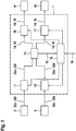
- the marking device 1 comprises a first receiver 11 for the signals 22a-22f of a first navigation system 2 and a second receiver 12 for the signals 32a-32d of a second navigation system 3.
- the signals 22a-22f, 32a-32d are from an evaluation unit 13 to a Feedback 14 processed, from which the position 15 of the marking device 1 can be determined.
- the marking device 1 includes a first transmitter 16 for transmitting the feedback 14, 15 to a first remote station 41 and a second transmitter 17 for transmitting the feedback 14, 15 to a second remote station 42nd
- the first navigation system 2 may be a high-accuracy, short-range ultra-wideband (UWB) navigation system
- the second navigation system 3 may be satellite-based.
- the first receiver 11 then has a much lower energy requirement than the second receiver 12.
- the first remote station 41 may be a station 21a-21c that belongs to the UWB navigation system 2 and transmits a signal 22a-22f to the first receiver 11.
- the marking device 1 can thus communicate bidirectionally with this station 21a-21c, as in FIG FIG. 3 is explained in more detail.
- the second remote station 42 may, for example, belong to a LoRaWAN network.
- the first transmitter 16 requires much less energy than the second for transmission over a very short distance to the first remote station 41 Transmitter 17 required for the transmission of a mean distance to the second remote station 42.
- the marking device 1 is of a in FIG. 1 not shown lifespan battery fed and therefore has an energy saving logic 18. If the first navigation system 2 is available at the location of the marking device 1, the energy-saving logic 18 switches on the first receiver 11 and the second receiver 12. If the first navigation system 2 is not available, the energy-saving logic 18 switches on the second receiver 12 and switches off the first receiver 11.
- the power saving logic 18 When a radio link to the first remote station 41 is available, the power saving logic 18 turns on the first transmitter 16 and the second transmitter 17 off. If no radio connection to the first remote station 41 is available, the energy-saving logic 18 switches on the second transmitter 17 and the first transmitter 16 off.
- the energy-saving logic 18 In order to decide whether the first navigation system 2, or the radio link to the first remote station 41, is available, the energy-saving logic 18 also draws the current position 15 of the marking device 1, determined by the evaluation unit 13, in the sense of a geo-ringing in this exemplary embodiment. The decision can also be specified by an external control signal 19.
- FIG. 2 shows by way of example and not to scale an industrialized building construction scenario in which finished parts 6a-6h are to be followed from production to use.
- a factory hall 51 in which a prefabricated part 6a shown here by way of example is produced.
- a first storage space on which example precast parts 6b to 6d dried, and a second storage space, are provided here on the example here finished parts 6e and 6f for removal.
- Each of the finished parts 6a-6h is provided with a marking device 1, which in FIG. 2 is not shown for reasons of clarity.
- the first navigation system 2 is available.
- the second navigation system 3 is available.
- a satellite-based navigation system is available globally.
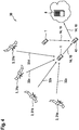
- FIG. 3 1 shows a scenario in which two marking devices 1 shown by way of example are located in the supply area 20 of the first navigation system 2.
- Three base stations 21a-21c of the first navigation system 2 send signals 22a-22f to the marking devices 1 and at the same time receive as respective remote stations 41 the respective feedback messages 14, from which the position 15 of the respective marking device 1 can be determined.
- the communication between the base stations 21a-21c on the one hand and the marking devices 1 on the other hand is therefore bidirectional.
- the base stations 21a-21c are interconnected.
- the base station 21c has an uplink connection, via which the collected feedbacks 14, 15 are transmitted from the marking devices 1 to an external server 8 for further evaluation and management.
- FIG. 4 1 shows a scenario in which two marking devices 1 shown by way of example are located only in the global coverage area 30 of the second navigation system 3, but not in the coverage area 20 of the first navigation system 2.
- the second navigation system 3 comprises four satellites 31 a - 31 d, which are shown here by way of example, which send signals 32 a - 32 d to the marking devices 1.
- the feedback 14, 15 from the Marker devices 1 are collected via LoRaWAN on a gateway 42, which serves all marking devices 1 as a common second remote station. Analogous to FIG. 3 the feedbacks 14, 15 of the marking devices 1 are collected and transmitted to an external server 8.
Applications Claiming Priority (1)
| Application Number | Priority Date | Filing Date | Title |
|---|---|---|---|
| DE102017216549.9A DE102017216549A1 (de) | 2017-09-19 | 2017-09-19 | Innerhalb und außerhalb von Gebäuden verwendbare Markierungsvorrichtung zur Lokalisierung von Objekten |
Publications (1)
| Publication Number | Publication Date |
|---|---|
| EP3457180A1 true EP3457180A1 (fr) | 2019-03-20 |
Family
ID=63579230
Family Applications (1)
| Application Number | Title | Priority Date | Filing Date |
|---|---|---|---|
| EP18194335.8A Withdrawn EP3457180A1 (fr) | 2017-09-19 | 2018-09-13 | Dispositif de marquage applicable à l'intérieur et à l'extérieur des bâtiments permettant de localiser des objets |
Country Status (2)
| Country | Link |
|---|---|
| EP (1) | EP3457180A1 (fr) |
| DE (1) | DE102017216549A1 (fr) |
Citations (7)
| Publication number | Priority date | Publication date | Assignee | Title |
|---|---|---|---|---|
| DE69416006T2 (de) | 1993-12-08 | 1999-08-19 | Caterpillar Inc | Methode und vorrichtung zum arbeitsfeldbezogenen betrieb eines verdichtungsgerätes |
| US20060109109A1 (en) * | 2004-11-19 | 2006-05-25 | Savi Technology, Inc. | Method and apparatus involving global positioning and long-range wireless link |
| DE602004004246T2 (de) | 2004-04-01 | 2007-11-15 | Heuristics Gmbh | Methode und System zur Erkennung von Defekten und gefährlichen Eigenschaften von passierenden Eisenbahnfahrzeugen |
| WO2009111734A2 (fr) * | 2008-03-07 | 2009-09-11 | Savi Technology, Inc. | Procédé et appareil de suivi et de surveillance de conteneurs |
| US8624725B1 (en) | 2011-09-22 | 2014-01-07 | Amazon Technologies, Inc. | Enhanced guidance for electronic devices having multiple tracking modes |
| US20140240143A1 (en) | 2013-02-27 | 2014-08-28 | Atrack Technology Inc. | Vehicle monitoring system and device |
| WO2017096046A1 (fr) * | 2015-12-03 | 2017-06-08 | Molex, Llc | Modules alimentés et systèmes et procédés de localisation et de réduction de la collision entre des paquets de ces derniers |
-
2017
- 2017-09-19 DE DE102017216549.9A patent/DE102017216549A1/de not_active Withdrawn
-
2018
- 2018-09-13 EP EP18194335.8A patent/EP3457180A1/fr not_active Withdrawn
Patent Citations (7)
| Publication number | Priority date | Publication date | Assignee | Title |
|---|---|---|---|---|
| DE69416006T2 (de) | 1993-12-08 | 1999-08-19 | Caterpillar Inc | Methode und vorrichtung zum arbeitsfeldbezogenen betrieb eines verdichtungsgerätes |
| DE602004004246T2 (de) | 2004-04-01 | 2007-11-15 | Heuristics Gmbh | Methode und System zur Erkennung von Defekten und gefährlichen Eigenschaften von passierenden Eisenbahnfahrzeugen |
| US20060109109A1 (en) * | 2004-11-19 | 2006-05-25 | Savi Technology, Inc. | Method and apparatus involving global positioning and long-range wireless link |
| WO2009111734A2 (fr) * | 2008-03-07 | 2009-09-11 | Savi Technology, Inc. | Procédé et appareil de suivi et de surveillance de conteneurs |
| US8624725B1 (en) | 2011-09-22 | 2014-01-07 | Amazon Technologies, Inc. | Enhanced guidance for electronic devices having multiple tracking modes |
| US20140240143A1 (en) | 2013-02-27 | 2014-08-28 | Atrack Technology Inc. | Vehicle monitoring system and device |
| WO2017096046A1 (fr) * | 2015-12-03 | 2017-06-08 | Molex, Llc | Modules alimentés et systèmes et procédés de localisation et de réduction de la collision entre des paquets de ces derniers |
Also Published As
| Publication number | Publication date |
|---|---|
| DE102017216549A1 (de) | 2019-03-21 |
Similar Documents
| Publication | Publication Date | Title |
|---|---|---|
| DE69631497T2 (de) | Verfahren für "Mutter"-Modus-Kommunikation mit stationärer Master-Ortungseinheit | |
| EP2999973B1 (fr) | Appareil mobile portable et détermination de position | |
| DE102004055033A1 (de) | Arbeitsgeländeverfolgungssystem und -verfahren | |
| EP3669312B1 (fr) | Procédé de commande, de surveillance et de visualisation de chantiers | |
| EP3353006A1 (fr) | Procédé et dispositif de détermination de la position absolue d'un véhicule | |
| WO2017144292A1 (fr) | Dispositif de repérage pour la localisation d'un objet | |
| DE102011051100A1 (de) | Verfahren und Referenzgerät zur Bereitstellung von Korrektursignalen für ein Satelliten gestütztes Positionsbestimmungssystem | |
| EP1153314B1 (fr) | Procede et dispositif pour determiner une position | |
| EP3457180A1 (fr) | Dispositif de marquage applicable à l'intérieur et à l'extérieur des bâtiments permettant de localiser des objets | |
| DE102014213066A1 (de) | Car2X fähige Warnkleidung mit Ladeschnittstelle | |
| EP3078934A1 (fr) | Systeme de mesure et procede de mesure | |
| WO2020182848A1 (fr) | Procédé et système de détermination de la position à l'intérieur de bâtiments | |
| EP1288673A2 (fr) | Dispositif de navigation mobile pour un réseau de radiocommunication cellulaire | |
| DE102020130550B4 (de) | Regionale Parametrisierung für LoRaWAN | |
| DE102017216546A1 (de) | Lokalisierung von Objekten mit ad-hoc einrichtbaren Signalstationen | |
| DE10028328A1 (de) | Ortungssystem | |
| EP3425610B1 (fr) | Procédé et système pour détection de véhicules dans un parking | |
| WO2018086780A1 (fr) | Système d'éclairage avec évaluation de signal d'analyse | |
| EP4248668A1 (fr) | Dispositif de terrain, module d'expansion et procédé de fonctionnement | |
| DE202011051720U1 (de) | Vorrichtung zur Übermittlung von ortsgebundenen Nachrichten von Fahrzeugen an eine ortsfeste Infrastruktur | |
| WO2001089250A1 (fr) | Procede de transfert d'appel d'urgence | |
| WO2023202813A1 (fr) | Système constitué d'un véhicule d'un appareil mobile pour déverrouiller le véhicule et/ou débloquer une fonction du véhicule | |
| DE102021204373A1 (de) | Zuverlässige Ortung einer UWB-Mobileinheit | |
| DE102016110001A1 (de) | Datenübertragungs- und Positionsmesssystem für Fahrzeuge | |
| DE102023121155A1 (de) | Ermitteln einer bodeneigenschaft unter verwendung einer maschine |
Legal Events
| Date | Code | Title | Description |
|---|---|---|---|
| PUAI | Public reference made under article 153(3) epc to a published international application that has entered the european phase |
Free format text: ORIGINAL CODE: 0009012 |
|
| AK | Designated contracting states |
Kind code of ref document: A1 Designated state(s): AL AT BE BG CH CY CZ DE DK EE ES FI FR GB GR HR HU IE IS IT LI LT LU LV MC MK MT NL NO PL PT RO RS SE SI SK SM TR |
|
| AX | Request for extension of the european patent |
Extension state: BA ME |
|
| 17P | Request for examination filed |
Effective date: 20190920 |
|
| RBV | Designated contracting states (corrected) |
Designated state(s): AL AT BE BG CH CY CZ DE DK EE ES FI FR GB GR HR HU IE IS IT LI LT LU LV MC MK MT NL NO PL PT RO RS SE SI SK SM TR |
|
| STAA | Information on the status of an ep patent application or granted ep patent |
Free format text: STATUS: THE APPLICATION IS DEEMED TO BE WITHDRAWN |
|
| 18D | Application deemed to be withdrawn |
Effective date: 20190921 |