EP3457001A1 - Schalteinrichtung für ein getriebe - Google Patents
Schalteinrichtung für ein getriebe Download PDFInfo
- Publication number
- EP3457001A1 EP3457001A1 EP17191109.2A EP17191109A EP3457001A1 EP 3457001 A1 EP3457001 A1 EP 3457001A1 EP 17191109 A EP17191109 A EP 17191109A EP 3457001 A1 EP3457001 A1 EP 3457001A1
- Authority
- EP
- European Patent Office
- Prior art keywords
- switching device
- idler gear
- sliding sleeve
- shaft
- extensions
- Prior art date
- Legal status (The legal status is an assumption and is not a legal conclusion. Google has not performed a legal analysis and makes no representation as to the accuracy of the status listed.)
- Granted
Links
Images






Classifications
-
- F—MECHANICAL ENGINEERING; LIGHTING; HEATING; WEAPONS; BLASTING
- F16—ENGINEERING ELEMENTS AND UNITS; GENERAL MEASURES FOR PRODUCING AND MAINTAINING EFFECTIVE FUNCTIONING OF MACHINES OR INSTALLATIONS; THERMAL INSULATION IN GENERAL
- F16H—GEARING
- F16H63/00—Control outputs from the control unit to change-speed- or reversing-gearings for conveying rotary motion or to other devices than the final output mechanism
- F16H63/02—Final output mechanisms therefor; Actuating means for the final output mechanisms
- F16H63/30—Constructional features of the final output mechanisms
-
- F—MECHANICAL ENGINEERING; LIGHTING; HEATING; WEAPONS; BLASTING
- F16—ENGINEERING ELEMENTS AND UNITS; GENERAL MEASURES FOR PRODUCING AND MAINTAINING EFFECTIVE FUNCTIONING OF MACHINES OR INSTALLATIONS; THERMAL INSULATION IN GENERAL
- F16H—GEARING
- F16H55/00—Elements with teeth or friction surfaces for conveying motion; Worms, pulleys or sheaves for gearing mechanisms
- F16H55/02—Toothed members; Worms
- F16H55/17—Toothed wheels
- F16H2055/178—Toothed wheels combined with clutch means, e.g. gear with integrated synchroniser clutch
-
- F—MECHANICAL ENGINEERING; LIGHTING; HEATING; WEAPONS; BLASTING
- F16—ENGINEERING ELEMENTS AND UNITS; GENERAL MEASURES FOR PRODUCING AND MAINTAINING EFFECTIVE FUNCTIONING OF MACHINES OR INSTALLATIONS; THERMAL INSULATION IN GENERAL
- F16H—GEARING
- F16H63/00—Control outputs from the control unit to change-speed- or reversing-gearings for conveying rotary motion or to other devices than the final output mechanism
- F16H63/02—Final output mechanisms therefor; Actuating means for the final output mechanisms
- F16H63/30—Constructional features of the final output mechanisms
- F16H2063/3093—Final output elements, i.e. the final elements to establish gear ratio, e.g. coupling sleeves or other means establishing coupling to shaft
-
- F—MECHANICAL ENGINEERING; LIGHTING; HEATING; WEAPONS; BLASTING
- F16—ENGINEERING ELEMENTS AND UNITS; GENERAL MEASURES FOR PRODUCING AND MAINTAINING EFFECTIVE FUNCTIONING OF MACHINES OR INSTALLATIONS; THERMAL INSULATION IN GENERAL
- F16H—GEARING
- F16H63/00—Control outputs from the control unit to change-speed- or reversing-gearings for conveying rotary motion or to other devices than the final output mechanism
- F16H63/02—Final output mechanisms therefor; Actuating means for the final output mechanisms
- F16H63/30—Constructional features of the final output mechanisms
- F16H63/38—Detents
Definitions
- the invention relates to a switching device for a transmission, in particular for a motor vehicle transmission.
- the invention further relates to a transmission with such a switching device.
- the DE 10 2008 000 647 A1 the applicant describes an arrangement for switching at least one idler gear on an associated shaft of a transmission.
- the idler gear can be coupled either with the associated shaft or with another idler gear.
- One of the embodiments shows a switching device with synchronization, wherein a sliding sleeve of the switching device is connected via driving elements with the idler gear.
- the driving elements are rotatably connected to the sliding sleeve, and engage positively in corresponding openings of the idler gear.
- a switching device for a transmission which is adapted for the manufacture of two switchable rotationally fixed connections, namely between a shaft of the transmission and a first idler gear associated with the shaft, and between the first idler gear and a second idler gear.
- the second idler gear is arranged coaxially to the same shaft.
- the switching device on a arranged between the first and second idler gear sliding sleeve.
- the rotationally fixed connection between the shaft and the first idler gear is produced, for example via a claw toothing.
- the rotationally fixed connection between the first idler gear and the second idler gear is produced.
- the first idler gear has a plurality of axially projecting extensions, which pass through openings formed in the sliding sleeve.
- the sliding sleeve and the first idler gear are positively connected in the direction of rotation.
- the axially projecting extensions do not hinder the production of the external teeth of the idler gear.
- the openings are preferably formed as through holes or as exemptions.
- a through hole in contrast to an exemption on a closed cross-section.
- the extensions have a circular cross-section.
- the extensions are formed as a cylinder, as a solid cylinder or as a hollow cylinder.
- the projections may be formed as axially projecting from the first idler ring ring segments.
- the extensions and the first idler gear are made in one piece.
- the extensions and the first idler gear are machined from a common blank, so that the extensions and the first idler gear need not be joined.
- a multi-part construction can be chosen so that the extensions are connected, for example via a press connection or a welded connection with the first idler gear. Depending on the design, such a multi-part design can reduce the manufacturing cost.
- the switching device has a neutral position, in which there is neither a rotationally fixed connection between the shaft and the first idler gear nor between the two idler gears. This is particularly advantageous for use in a multi-speed automotive transmission.
- At least one of the idler gears is associated with a synchronizer.
- the production of the respective non-rotatable connection takes place only at synchronous speed of the components involved.
- at least one of the switchable non-rotatable connections via an unsynchronized dog teeth can be produced.
- the switching device has a pressure piece holder.
- the pressure piece holder is adapted to support a spring-loaded pressure piece, for example a ball.
- the sliding sleeve can be latched in at least one axial position, in which the pressure piece engages in a corresponding recess in the sliding sleeve.
- the pressure piece holder may be centered on an inner side of the extensions.
- the pressure piece holder is preferably rotatably connected to the sliding sleeve.
- the pressure piece holder can be centered on the first or second loose wheel via a bearing, preferably via a bearing.
- the pressure piece holder may be centered on the shaft.
- the switching device according to the invention may be part of a transmission for a motor vehicle transmission.
- a transmission referred to here in particular a multi-speed transmission in which a plurality of gears, so fixed ratios between a drive shaft and an output shaft of the transmission can be switched.
- the switching device is preferably used to produce two such gears. Since by means of the switching device two idler gears are rotatably coupled to each other, the switching device is particularly suitable for the production of a Windungsganges.
- Fig. 1 shows a sectional view of a first embodiment of a switching device according to the invention 1.
- the switching device 1 is adapted for producing a switchable rotationally fixed connection between a shaft W and a first idler gear LR1, which is rotatably mounted on the shaft W via a first needle bearing NL1.
- the switching device 1 is further adapted for producing a switchable rotationally fixed connection between the first idler gear LR1 and a second idler gear LR2, which is coaxial with the shaft W and rotatably mounted on the shaft W via a second needle bearing NL2.
- the second needle bearing NL2 is exemplified as a double-row bearing.
- a sliding sleeve S is arranged between the first and second idler gear LR1, LR2 .
- the sliding sleeve S has on its outer circumference on a circumferential groove into which a non-illustrated actuator can engage positively, for example, a shift fork.
- a non-illustrated actuator can engage positively, for example, a shift fork.
- a non-illustrated actuator can engage positively, for example, a shift fork.
- a non-illustrated actuator can engage positively, for example, a shift fork.
- a coupling body KK1 is rotatably connected to the shaft W.
- the coupling body KK1 has a bevel, which cooperates with a synchronizer SY1.
- the synchronizer SY1 is set up in a known manner to allow the production of the rotationally fixed connection between the shaft W and the first idler gear LR1 only when the shaft W and the first idler gear LR1 have the same speed.
- the sliding sleeve S is positively connected to the first idler gear LR1 by axially projecting extensions F are formed on the first idler gear LR1.
- the extensions F engage in recesses A of the sliding sleeve S, which are not visible in the illustrated sectional view. If now the sliding sleeve S is displaced in the direction of the second loose wheel LR2, the rotationally fixed connection between the two loose wheels LR1, LR2 is established.
- This rotationally fixed connection is made via the extensions F, the sliding sleeve S connected to the extensions F and via a coupling body KK2.
- the coupling body KK2 is rotatably connected to the second idler gear LR2 and has a slope, which cooperates with a synchronizer SY2.
- the synchronizer SY2 is set up in a known manner to allow the production of the rotationally fixed connection between the sliding sleeve S and the coupling body KK2 only when the two idler gears LR1, LR2 have the same
- the first idler gear LR1 is rotatably connected neither to the shaft W nor to the second idler gear LR2.
- This middle position of the sliding sleeve S corresponds to a neutral position of the switching device 1.
- the neutral position does not correspond to a middle position of the sliding sleeve, but a disengaged from the middle position.
- the first idler gear could be coupled to the shaft.
- the neutral position of the switching device could be present.
- shifting in a second direction opposite the first direction the coupling could occur the two loose wheels take place.
- such embodiments are not shown in the figures.
- the switching device 1 has a pressure piece holder DH, which is rotatably connected via a toothing with the shaft W.
- the pressure piece holder DH is set up on its outer circumference to support a spring-loaded pressure piece D.
- the sliding sleeve S can be locked at least in its middle position.
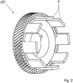
- Fig. 2 shows an isometric view of the first idler gear LR1 of the switching device 1 according to Fig. 1 , It can clearly be seen that the extensions F are formed by ring segments projecting from the first idler gear LR1. The extensions F and the idler LR1 form a one-piece construction.
- Fig. 3 shows an isometric view of the sliding sleeve S of the switching device 1 according to Fig. 1 ,
- the openings A formed in the sliding sleeve S can be clearly seen, which are formed as through-holes in the present construction.
- the openings A are dimensioned such that an axial displacement of the sliding sleeve S relative to the first idler gear LR1 is possible, guided axially by the extensions F.
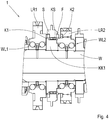
- Fig. 4 shows a sectional view of a second embodiment of the switching device according to the invention 1.
- a dog teeth K1 is formed on the outer circumference of the shaft W rotatably connected to the coupling body KK1 .
- a complementary dog teeth KS is formed at the inner diameter of the sliding sleeve S . If the sliding sleeve S is displaced by an actuator, not shown, in the direction of the first idler gear LR1, a form-locking rotationally fixed connection between the coupling body KK1 and the first idler gear LR1 is produced via the claw toothings K1 and KS.
- Fig. 5 shows an isometric view of the first idler gear LR1 of the switching device 1 according to Fig. 4 , It can clearly be seen that the extensions F are formed by three ring segments protruding from the first idler gear LR1. The extensions F and the idler LR1 form a one-piece construction.
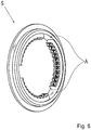
- Fig. 6 shows an isometric view of the sliding sleeve S of the switching device 1 according to Fig. 4 , wherein, the formed in the sliding sleeve S openings A are clearly visible, which are formed in the present construction as exemptions in the driving teeth of the sliding sleeve S.
- the openings A are dimensioned such that an axial displacement of the sliding sleeve S relative to the first idler gear LR1 is possible, guided axially by the extensions F.
- Fig. 7 shows a sectional view according to a variant of in Figure 7 illustrated construction.
- the extensions F are now formed as cylindrical pins with a circular cross section, which are connected by means of a press connection with the first idler gear LR1.
- the extensions F can be welded to the first idler gear LR1.
- the corresponding weld could be arranged in the recess on that end face of the first idler gear LR1, which is opposite to the coupling body KK1.
- Fig. 8 shows an isometric view of the first idler gear LR1 according to the in Fig. 7 illustrated construction. It can be seen clearly that the extensions F are formed by six protruding from the first idler gear LR1 pins with a circular cross-section.
- Fig. 9 shows an isometric view of the sliding sleeve S according to the in Fig. 7 illustrated construction.
- the formed in the sliding sleeve S openings A are clearly visible, which are designed as bores in the present construction.
- the openings A are dimensioned such that an axial displacement of the sliding sleeve S relative to the first idler gear LR1 is possible, guided axially by the extensions F.
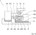
- Fig. 10 shows a schematic diagram of a third embodiment of the switching device 1 with synchronizers SY1, SY2.
- the switching device 1, an optional sleeve H, which is arranged between the shaft W and the second needle bearing NL2.
- the second idler gear LR2 has an axially projecting in the direction of the first idler gear LR1 extension LR2F.
- the coupling body KK2 is rotatably connected via the extension LR2F with the idler gear LR2.
- the extension LR2F is used to mount the pressure piece holder DH, which is rotatably supported and centered via a needle bearing DHL on the extension LR2F.
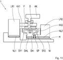
- Fig. 11 shows a schematic diagram of a fourth embodiment of the switching device 1 with synchronizers SY1, SY2.
- the pressure piece holder DH is not rotatably mounted on the second loose wheel LR2, but on the shaft W.
- the corresponding needle bearing DHL is supported on the sleeve H.
- the sleeve H is only optional.
- Pressure piece holder DH and second idler gear LR2 are axially separated by a spacer SP.
- the spacer SP may be formed, for example, as a thrust washer.
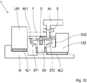
- Fig. 12 shows a schematic diagram of a fifth embodiment of the switching device 1 with synchronizers SY1, SY2.
- the pressure piece holder DH is centered on its outer circumference on an inner side of the extensions F of the first idler gear LR1.
- the pressure piece holder DH is rotatably connected to the extensions F.
- Fig. 13 schematically shows a drive train of a motor vehicle.
- the drive train has an internal combustion engine VM, to which a transmission G is connected.
- the transmission G is preferably a multi-speed transmission in which a plurality of gears, ie fixed gear ratios between a drive shaft and an output shaft of the transmission G are preferably automatically switchable.
- the speed and torque output characteristic of the internal combustion engine VM can be adapted to the driving resistance of the vehicle in a suitable manner.
- the transmission G is connected on the output side with a differential gear AG, via which the power applied to the transmission G output side can be distributed to drive wheels DW of the motor vehicle.
- the transmission G has a switching device 1 according to one of the embodiments described above, wherein the switching device 1 is preferably adapted to the production of two gears of the transmission G.
- the transmission G may be, for example, an automated transmission, such as a dual-clutch transmission.
- the transmission G may alternatively be a manually shifted transmission.
- the switching device 1 could also be used for coupling a shaft of a first transmission with a shaft of a second transmission.
- First and second transmissions may be sub-transmissions of a total transmission.
- the switching device could be used to couple a pre or Nachschaltradsatzes with a main transmission.
- Such group transmissions are used for example in commercial vehicles.
- the in Fig. 13 shown construction of the drive train is to be regarded as exemplary only. Instead of the illustrated structure with aligned longitudinally to the direction of travel of the motor vehicle powertrain is also a use in a direction transverse to the direction of travel aligned powertrain conceivable.
- the differential gear AG may be integrated in the transmission G.
Landscapes
- Engineering & Computer Science (AREA)
- General Engineering & Computer Science (AREA)
- Mechanical Engineering (AREA)
- Structure Of Transmissions (AREA)
- Gear-Shifting Mechanisms (AREA)
Abstract
Description
- Die Erfindung betrifft eine Schalteinrichtung für ein Getriebe, insbesondere für ein Kraftfahrzeuggetriebe. Die Erfindung betrifft ferner ein Getriebe mit einer solchen Schalteinrichtung.
- Die
DE 10 2008 000 647 A1 der Anmelderin beschreibt eine Anordnung zum Schalten von zumindest einem Losrad an einer zugeordneten Welle eines Getriebes. Mit der darin offenbarten Schalteinrichtung kann das Losrad entweder mit der zugeordneten Welle oder mit einem weiteren Losrad gekoppelt werden. Eines der Ausführungsbeispiele zeigt eine Schalteinrichtung mit Synchronisierung, wobei eine Schiebemuffe der Schalteinrichtung über Mitnahmeelemente mit dem Losrad verbunden ist. Die Mitnahmeelemente sind mit der Schiebemuffe drehfest verbunden, und greifen formschlüssig in entsprechende Öffnungen des Losrades ein. - Eine derartige Ausgestaltung ist für die Fertigung der Schiebemuffe jedoch nachteilig, da aufgrund der Mitnahmeelemente eine Innenverzahnung der Schiebemuffe nur mit erhöhtem Aufwand herstellbar ist.
- Es ist daher Aufgabe der Erfindung die im Stand der Technik bekannte Schaltanordnung weiterzuentwickeln.
- Die Aufgabe wird gelöst durch die Merkmale des Patentanspruchs 1. Vorteilhafte Ausgestaltungen ergeben sich aus den Unteransprüchen, der Beschreibung sowie aus den Figuren.
- Es wird eine Schalteinrichtung für ein Getriebe vorgeschlagen, welche zum Herstellen von zwei schaltbaren drehfesten Verbindungen eingerichtet ist, nämlich zwischen einer Welle des Getriebes und einem der Welle zugeordneten ersten Losrad, und zwischen dem ersten Losrad und einem zweiten Losrad. Das zweite Losrad koaxial zur selben Welle angeordnet.
- Dazu weist die Schalteinrichtung eine zwischen dem ersten und zweiten Losrad angeordnete Schiebemuffe auf. Durch Verschiebung der Schiebemuffe in Richtung des ersten Losrades wird die drehfeste Verbindung zwischen der Welle und dem ersten Losrad hergestellt, beispielsweise über eine Klauenverzahnung. Durch Verschiebung der Schiebemuffe in Richtung des zweiten Losrades wird die drehfeste Verbindung zwischen dem ersten Losrad und dem zweiten Losrad hergestellt.
- Erfindungsgemäß weist das erste Losrad eine Mehrzahl von axial vorstehenden Fortsätzen auf, welche durch in der Schiebemuffe ausgebildete Öffnungen hindurchreichen. Dadurch sind die Schiebemuffe und das erste Losrad in Drehrichtung formschlüssig verbunden. Die axial vorstehenden Fortsätze behindern die Fertigung der Außenverzahnung des Losrades nicht.
- Die Öffnungen sind vorzugsweise als Durchgangslöcher oder als Freistellungen gebildet. Ein Durchgangsloch weist im Unterschied zu einer Freistellung einen geschlossenen Querschnitt auf. Mittels beider Ausführungsformen kann ein Formschluss zwischen Schiebemuffe und erstem Losrad gebildet werden.
- Vorzugsweise weisen die Fortsätze einen kreisrunden Querschnitt auf. In anderen Worten sind die Fortsätze als Zylinder ausgebildet, als Vollzylinder oder als Hohlzylinder. Alternativ dazu können die die Fortsätze als vom ersten Losrad axial hervorstehende Ringsegmente ausgebildet sein.
- Gemäß einer bevorzugten Ausgestaltung sind die Fortsätze und das erste Losrad einteilig ausgeführt. In anderen Worten werden die Fortsätze und das erste Losrad aus einem gemeinsamen Rohteil bearbeitet, sodass die Fortsätze und das erste Losrad nicht gefügt werden müssen. Dadurch ist eine besonders kompakte Bauweise möglich, da auf Fügestellen verzichtet werden kann. Alternativ dazu kann eine mehrteilige Konstruktion gewählt werden, sodass die Fortsätze beispielsweise über eine Pressverbindung oder eine Schweißverbindung mit dem ersten Losrad verbunden sind. Je nach Ausführung kann eine solche mehrteilige Konstruktion den Herstellungsaufwand verringern.
- Vorzugsweise weist die Schalteinrichtung eine Neutralstellung auf, in der weder zwischen der Welle und dem ersten Losrad noch zwischen den beiden Losrädern eine drehfeste Verbindung besteht. Dies ist besonders für die Anwendung in einem Kraftfahrzeuggetriebe mit mehreren Gängen vorteilhaft.
- Vorzugsweise ist zumindest einem der Losräder eine Synchronisiereinrichtung zugeordnet. Mittels der Synchronisiereinrichtung erfolgt die Herstellung der jeweiligen drehfesten Verbindung erst bei Synchrondrehzahl der beteiligten Bauelemente. Alternativ dazu ist zumindest eine der schaltbaren drehfesten Verbindungen über eine unsynchronisierte Klauenverzahnung herstellbar.
- Gemäß einer bevorzugten Ausgestaltung weist die Schalteinrichtung einen Druckstückhalter auf. Der Druckstückhalter ist dazu eingerichtet ein federbelastetes Druckstück abzustützen, beispielsweise eine Kugel. Mittels des Druckstücks kann die Schiebemuffe in zumindest einer axialen Stellung rastiert werden, in dem das Druckstück in eine entsprechende Ausnehmung in der Schiebemuffe eingreift. Der Druckstückhalter kann an einer Innenseite der Fortsätze zentriert sein. Dazu ist der Druckstückhalter mit der Schiebemuffe vorzugsweise drehfest verbunden. Alternativ zur Zentrierung an der Innenseite der Fortsätze kann der Druckstückhalter am ersten oder zweiten Losrad über ein Lager zentriert sein, vorzugsweise über ein Lager. Gemäß einer weiteren möglichen Alternative kann der Druckstückhalter an der Welle zentriert sein.
- Die erfindungsgemäße Schalteinrichtung kann Bestandteil eines Getriebes für ein Kraftfahrzeuggetriebe sein. Ein Getriebe bezeichnet hier insbesondere ein mehrgängiges Getriebe, bei dem eine Vielzahl von Gängen, also feste Übersetzungsverhältnisse zwischen einer Antriebswelle und einer Abtriebswelle des Getriebes schaltbar sind. Die Schalteinrichtung dient bevorzugt zur Herstellung zwei solcher Gänge. Da mittels der Schalteinrichtung zwei Losräder miteinander drehfest koppelbar sind, eignet sich die Schalteinrichtung besonders für die Herstellung eines Windungsganges.
- Ausführungsbeispiele der Erfindung sind nachfolgend anhand der beigefügten Figuren detailliert beschrieben. Es zeigen:
- Fig. 1
- eine Schnittansicht einer erfindungsgemäßen Schalteinrichtung mit Synchronisierung;
- Fig. 2
- eine isometrische Ansicht eines Losrades der Schalteinrichtung ;
- Fig. 3
- eine isometrische Ansicht einer Schiebemuffe der Schalteinrichtung;
- Fig. 4
- eine Schnittansicht einer erfindungsgemäßen Schalteinrichtung ohne Synchronisierung;
- Fig. 5
- eine isometrische Ansicht eines Losrades der Schalteinrichtung ohne Synchronisierung;
- Fig. 6
- eine isometrische Ansicht einer Schiebemuffe der Schalteinrichtung ohne Synchronisierung;
- Fig. 7
- eine Schnittansicht eines Teils der erfindungsgemäßen Schalteinrichtung ohne Synchronisierung;
- Fig. 8
- eine isometrische Ansicht eines Losrades gemäß
Fig. 7 ; - Fig. 9
- eine isometrische Ansicht einer Schiebemuffe gemäß
Fig. 7 ; - Fig. 10
- bis
Fig. 12 je eine Prinzipskizze von verschiedenen Lagerungen eines Druckstückhalters der erfindungsgemäßen Schalteinrichtung; und - Fig. 13
- schematisch einen Antriebsstrang eines Kraftfahrzeugs.
-
Fig. 1 zeigt eine Schnittansicht eines ersten Ausführungsbeispiels einer erfindungsgemäßen Schalteinrichtung 1. Die Schalteinrichtung 1 ist zum Herstellen einer schaltbaren drehfesten Verbindung zwischen einer Welle W und eines ersten Losrades LR1 eingerichtet, welches auf der Welle W über ein erstes Nadellager NL1 drehbar gelagert ist. Die Schalteinrichtung 1 ist ferner zum Herstellen einer schaltbaren drehfesten Verbindung zwischen dem ersten Losrad LR1 und einem zweiten Losrad LR2 eingerichtet, welches koaxial zur Welle W angeordnet und auf der Welle W über ein zweites Nadellager NL2 drehbar gelagert ist. Das zweite Nadellager NL2 ist beispielhaft als ein zweireihiges Lager ausgebildet. - Zwischen dem ersten und zweiten Losrad LR1, LR2 ist eine Schiebemuffe S angeordnet. Die Schiebemuffe S weist an ihrem Außenumfang eine umlaufende Nut auf, in die ein nicht dargestellter Aktuator formschlüssig eingreifen kann, beispielsweise eine Schaltgabel. Die in
Fig. 1 dargestellte Ausgestaltung der formschlüssigen Schnittstelle zwischen Schaltgabel und Schiebemuffe S ist nur beispielhaft anzusehen. Wird die Schiebemuffe S durch den Aktuator in Richtung des ersten Losrades LR1 axial verschoben, so wird die drehfeste Verbindung zwischen der Welle W und dem ersten Losrad LR1 hergestellt. Dazu ist ein Kupplungskörper KK1 mit der Welle W drehfest verbunden. Der Kupplungskörper KK1 weist eine Schräge auf, welche mit einer Synchronisiereinrichtung SY1 zusammenwirkt. Die Synchronisiereinrichtung SY1 ist in bekannter Weise dazu eingerichtet, das Herstellen der drehfesten Verbindung zwischen Welle W und erstem Losrad LR1 erst dann zuzulassen, wenn Welle W und erstes Losrad LR1 die gleiche Drehzahl aufweisen. - Die Schiebemuffe S ist mit dem ersten Losrad LR1 formschlüssig verbunden, indem am ersten Losrad LR1 axial vorstehende Fortsätze F ausgebildet sind. Die Fortsätze F greifen in Ausnehmungen A der Schiebemuffe S ein, welche in der dargestellten Schnittansicht nicht sichtbar sind. Wird nun die Schiebemuffe S in Richtung des zweiten Losrades LR2 verschoben, so wird die drehfeste Verbindung zwischen den beiden Losrädern LR1, LR2 hergestellt. Diese drehfeste Verbindung wird über die Fortsätze F, die mit den Fortsätzen F verbundene Schiebemuffe S sowie über einen Kupplungskörper KK2 hergestellt. Der Kupplungskörper KK2 ist mit dem zweiten Losrad LR2 drehfest verbunden und weist eine Schräge auf, welche mit einer Synchronisiereinrichtung SY2 zusammenwirkt. Die Synchronisiereinrichtung SY2 ist in bekannter Weise dazu eingerichtet, das Herstellen der drehfesten Verbindung zwischen der Schiebemuffe S und dem Kupplungskörper KK2 erst dann zuzulassen, wenn die beiden Losräder LR1, LR2 die gleiche Drehzahl aufweisen.
- In einer Mittelstellung der Schiebemuffe S ist das erste Losrad LR1 weder mit der Welle W noch mit dem zweiten Losrad LR2 drehfest verbunden. Diese Mittelstellung der Schiebemuffe S entspricht einer Neutralstellung der Schalteinrichtung 1. Es sind auch andere Ausführungen denkbar, bei denen die Neutralstellung nicht einer Mittelstellung der Schiebemuffe, sondern einer aus der Mitte ausgerückten Stellung entspricht. Beispielsweise könnte in der Mittelstellung das erste Losrad mit der Welle gekoppelt sein. Bei einer Verschiebung der Schiebemuffe in eine erste Richtung könnte die Neutralstellung der Schalteinrichtung vorliegen. Bei einer Verschiebung in eine der ersten Richtung entgegengesetzten zweiten Richtung könnte die Koppelung der beiden Losräder erfolgen. Der Übersichtlichkeit halber sind derartige Ausführungen nicht in den Figuren dargestellt.
- Die Schalteinrichtung 1 weist einen Druckstückhalter DH auf, welcher über eine Verzahnung mit der Welle W drehfest verbunden ist. Der Druckstückhalter DH ist an seinem Außenumfang dazu eingerichtet ein federbelastetes Druckstück D abzustützen. Über das Druckstück D kann die Schiebemuffe S zumindest in ihrer Mittelstellung verrastet werden.
-
Fig. 2 zeigt eine isometrische Ansicht des ersten Losrades LR1 der Schalteinrichtung 1 gemäßFig. 1 . Darin ist deutlich zu erkennen, dass die Fortsätze F durch vom ersten Losrad LR1 hervorstehende Ringsegmente gebildet sind. Die Fortsätze F und das Losrad LR1 bilden eine einteilige Konstruktion. -
Fig. 3 zeigt eine isometrische Ansicht der Schiebemuffe S der Schalteinrichtung 1 gemäßFig. 1 . Darin sind die in der Schiebemuffe S ausgebildeten Öffnungen A deutlich zu erkennen, welche in der vorliegenden Konstruktion als Durchgangslöcher ausgebildet sind. Die Öffnungen A sind derart dimensioniert, dass ein axiales Verschieben der Schiebemuffe S relativ zum ersten Losrad LR1 möglich ist, axial geführt durch die Fortsätze F. -
Fig. 4 zeigt eine Schnittansicht eines zweiten Ausführungsbeispiels der erfindungsgemäßen Schalteinrichtung 1. Im Unterschied zum Ausführungsbeispiel gemäßFig. 1 ist nun keine Synchronisiereinrichtung vorgesehen. Am Außenumfang des mit der Welle W drehfest verbundenen Kupplungskörpers KK1 ist eine Klauenverzahnung K1 ausgebildet. Am Innendurchmesser der Schiebemuffe S ist eine dazu komplementäre Klauenverzahnung KS ausgebildet. Wird die Schiebemuffe S durch einen nicht dargestellten Aktuator in Richtung des ersten Losrades LR1 verschoben, so wird über die Klauenverzahnungen K1 und KS eine formschlüssige drehfeste Verbindung zwischen dem Kupplungskörper KK1 und dem ersten Losrad LR1 hergestellt. Da der Kupplungskörper KK1 mit der Welle W drehfest verbunden ist, und die Schiebemuffe S über die Fortsätze F mit dem ersten Losrad LR1 verbunden ist, wird somit eine drehfeste Verbindung zwischen dem ersten Losrad LR1 und der Welle W hergestellt. - Am zweiten Losrad LR2 ist eine zur Klauenverzahnung KS der Schaltmuffe S komplementäre Klauenverzahnung K2 ausgebildet. Wird die Schiebemuffe S ausgehend von ihrer Neutralstellung in Richtung des zweiten Losrades LR2 verschoben, so wird über die Klauenverzahnungen KS und K2 eine formschlüssige drehfeste Verbindung zwischen der Schiebemuffe S und dem zweiten Losrad LR2 hergestellt. Da die Schiebemuffe S über die Fortsätze F mit dem ersten Losrad LR1 verbunden ist, wird somit eine drehfeste Verbindung zwischen den beiden Losrädern LR1, LR2 hergestellt. In dieser Stellung ist die Klauenverzahnung K1 nicht mit der Klauenverzahnung KS im Eingriff.
-
Fig. 5 zeigt eine isometrische Ansicht des ersten Losrades LR1 der Schalteinrichtung 1 gemäßFig. 4 . Darin ist deutlich zu erkennen, dass die Fortsätze F durch drei vom ersten Losrad LR1 hervorstehende Ringsegmente gebildet sind. Die Fortsätze F und das Losrad LR1 bilden eine einteilige Konstruktion. -
Fig. 6 zeigt eine isometrische Ansicht des Schiebemuffe S der Schalteinrichtung 1 gemäßFig. 4 . Darin sind die in der Schiebemuffe S ausgebildeten Öffnungen A deutlich zu erkennen, welche in der vorliegenden Konstruktion als Freistellungen in der Mitnahmeverzahnung der Schiebemuffe S ausgebildet sind. Die Öffnungen A sind derart dimensioniert, dass ein axiales Verschieben der Schiebemuffe S relativ zum ersten Losrad LR1 möglich ist, axial geführt durch die Fortsätze F. -
Fig. 7 zeigt eine Schnittansicht gemäß einer Variante der inFig.7 dargestellten Konstruktion. Die Fortsätze F sind nun als zylindrische Stifte mit kreisrundem Querschnitt ausgebildet, welche mittels einer Pressverbindung mit dem ersten Losrad LR1 verbunden sind. Alternativ dazu können die Fortsätze F mit dem ersten Losrad LR1 verschweißt werden. Die entsprechende Schweißnaht könnte in der Ausnehmung auf jener Stirnseite des ersten Losrades LR1 angeordnet sein, welche dem Kupplungskörper KK1 gegenüberliegt. -
Fig. 8 zeigt eine isometrische Ansicht des ersten Losrades LR1 gemäß der inFig. 7 dargestellten Konstruktion. Darin ist deutlich zu erkennen, dass die Fortsätze F durch sechs vom ersten Losrad LR1 hervorstehende Stifte mit kreisrundem Querschnitt gebildet sind. -
Fig. 9 zeigt eine isometrische Ansicht des Schiebemuffe S gemäß der inFig. 7 dargestellten Konstruktion. Darin sind die in der Schiebemuffe S ausgebildeten Öffnungen A deutlich zu erkennen, welche in der vorliegenden Konstruktion als Bohrungen ausgeführt sind. Die Öffnungen A sind derart dimensioniert, dass ein axiales Verschieben der Schiebemuffe S relativ zum ersten Losrad LR1 möglich ist, axial geführt durch die Fortsätze F. -
Fig. 10 zeigt eine Prinzipskizze eines dritten Ausführungsbeispiels der Schalteinrichtung 1 mit Synchronisiereinrichtungen SY1, SY2. Im Unterschied zum inFig.1 dargestellten ersten Ausführungsbeispiel weist die Schalteinrichtung 1 eine optionale Hülse H auf, welche zwischen der Welle W und dem zweiten Nadellager NL2 angeordnet ist. Das zweite Losrad LR2 weist einen axial in Richtung des ersten Losrades LR1 hervorstehenden Fortsatz LR2F auf. Der Kupplungskörper KK2 ist über den Fortsatz LR2F drehfest mit dem Losrad LR2 verbunden. Zusätzlich dient der Fortsatz LR2F der Lagerung des Druckstückhalters DH, welcher über ein Nadellager DHL am Fortsatz LR2F drehbar gelagert und zentriert ist. -
Fig. 11 zeigt eine Prinzipskizze eines vierten Ausführungsbeispiels der Schalteinrichtung 1 mit Synchronisiereinrichtungen SY1, SY2. Im Unterschied zum inFig.10 dargestellten dritten Ausführungsbeispiel ist der Druckstückhalter DH nicht am zweiten Losrad LR2, sondern an der Welle W drehbar gelagert. Das entsprechende Nadellager DHL stützt sich an der Hülse H ab. Die Hülse H ist nur optional vorgesehen. Druckstückhalter DH und zweites Losrad LR2 sind axial durch ein Distanzstück SP voneinander getrennt. Das Distanzstück SP kann beispielsweise als Anlaufscheibe ausgebildet sein. -
Fig. 12 zeigt eine Prinzipskizze eines fünften Ausführungsbeispiels der Schalteinrichtung 1 mit Synchronisiereinrichtungen SY1, SY2. Im Unterschied zum inFig. 10 dargestellten dritten Ausführungsbeispiel ist der Druckstückhalter DH an seinem Außenumfang an einer Innenseite der Fortsätze F des ersten Losrades LR1 zentriert. Dabei ist der Druckstückhalter DH mit den Fortsätzen F drehfest verbunden. -
Fig. 13 zeigt schematisch einen Antriebsstrang eines Kraftfahrzeugs. Der Antriebsstrang weist einen Verbrennungsmotor VM auf, an den ein Getriebe G angeschlossen ist. Das Getriebe G ist vorzugsweise ein mehrgängiges Getriebe, bei dem eine Vielzahl von Gängen, also feste Übersetzungsverhältnisse zwischen einer Antriebswelle und einer Abtriebswelle des Getriebes G vorzugsweise automatisch schaltbar sind. Durch ein solches Getriebe G kann die Drehzahl- und Drehmomentabgabecharakteristik des Verbrennungsmotors VM den Fahrwiderständen des Fahrzeugs in geeigneter Weise angepasst werden. Das Getriebe G ist abtriebsseitig mit einem Differentialgetriebe AG verbunden, über das die am Getriebe G abtriebsseitig anliegende Leistung auf Antriebsräder DW des Kraftfahrzeugs verteilt werden kann. - Das Getriebe G weist eine Schalteinrichtung 1 nach einem der zuvor beschriebenen Ausführungsbeispiele auf, wobei die Schalteinrichtung 1 vorzugsweise an der Herstellung von zwei Gängen des Getriebes G eingerichtet ist. Das Getriebe G kann beispielsweise ein automatisiertes Getriebe sein, beispielsweise ein Doppelkupplungsgetriebe. Das Getriebe G kann alternativ dazu ein manuell geschaltetes Getriebe sein.
- Die Schalteinrichtung 1 könnte auch zur Koppelung einer Welle eines ersten Getriebes mit einer Welle eines zweiten Getriebes verwendet werden. Erstes und zweites Getriebe können Sub-Getriebe eines Gesamtgetriebes sein. Beispielsweise könnte die Schalteinrichtung zur Koppelung eines Vor- oder Nachschaltradsatzes mit einem Hauptgetriebe verwendet werden. Derartige Gruppengetriebe kommen beispielsweise in Nutzfahrzeugen zum Einsatz.
- Der in
Fig. 13 dargestellte Aufbau des Antriebsstrangs ist lediglich beispielhaft anzusehen. Statt dem dargestellten Aufbau mit längs zur Fahrtrichtung des Kraftfahrzeugs ausgerichtetem Antriebsstrang ist auch eine Verwendung in einem quer zur Fahrtrichtung ausgerichtetem Antriebsstrang denkbar. Das Differentialgetriebe AG kann in das Getriebe G integriert sein. -
- 1
- Schalteinrichtung
- G
- Getriebe
- W
- Welle
- LR1
- Erstes Losrad
- F
- Fortsätze
- NL1
- Erstes Nadellager
- LR2
- Zweites Losrad
- NL2
- Zweites Nadellager
- LR2F
- Fortsatz
- S
- Schiebemuffe
- A
- Öffnungen
- SY1, SY2
- Synchronisiereinrichtung
- K1, K2, KS
- Klauenverzahnung
- KK1, KK2
- Kupplungskörper
- DH
- Druckstückhalter
- D
- Druckstück
- DHL
- Nadellager
- H
- Hülse
- SP
- Distanzstück
- AK
- Aktuator
- VM
- Verbrennungsmotor
- AG
- Differentialgetriebe
- DW
- Antriebsrad
Claims (15)
- Schalteinrichtung (1) für ein Getriebe (G) zum Herstellen einer schaltbaren drehfesten Verbindung zwischen- einer Welle (W) des Getriebes (G) und einem der Welle (W) zugeordneten ersten Losrad (LR1),- sowie zwischen dem ersten Losrad (LR1) und einem koaxial zur Welle (W) angeordneten zweiten Losrad (LR2),
wobei die Schalteinrichtung (1) eine zwischen dem ersten und zweiten Losrad (LR1, LR2) angeordnete Schiebemuffe (S) aufweist,- wobei durch Verschiebung der Schiebemuffe (S) in Richtung des ersten Losrades (LR1) die drehfeste Verbindung zwischen der Welle (W) und dem ersten Losrad (LR1) herstellbar ist,- wobei durch Verschiebung der Schiebemuffe (S) in Richtung des zweiten Losrades (LR2) die drehfeste Verbindung zwischen dem ersten Losrad (LR1) und dem zweiten Losrad (LR2) herstellbar ist,dadurch gekennzeichnet, dass das erste Losrad (LR1) eine Mehrzahl von axial vorstehenden Fortsätzen (F) aufweist, welche durch in der Schiebemuffe (S) ausgebildete Öffnungen (A) hindurchreichen. - Schalteinrichtung (1) nach Anspruch 1, dadurch gekennzeichnet, dass die Öffnungen (A) durch Durchgangslöcher oder durch Freistellungen gebildet werden.
- Schalteinrichtung (1) nach Anspruch 1 oder Anspruch 2, dadurch gekennzeichnet, dass die Fortsätze (F) einen kreisrunden Querschnitt aufweisen.
- Schalteinrichtung (1) nach Anspruch 1 oder Anspruch 2, dadurch gekennzeichnet, dass die Fortsätze (F) durch vom ersten Losrad (LR1) hervorstehende Ringsegmente gebildet sind.
- Schalteinrichtung (1) nach einem der vorangehenden Ansprüche, dadurch gekennzeichnet, dass die Fortsätze (F) und das erste Losrad (LR1) einteilig ausgeführt sind.
- Schalteinrichtung (1) nach einem der Ansprüche 1 bis 4, dadurch gekennzeichnet, dass die Fortsätze (F) über eine Pressverbindung oder eine Schweißverbindung mit dem ersten Losrad (LR1) verbunden sind.
- Schalteinrichtung (1) nach einem der vorangehenden Ansprüche, dadurch gekennzeichnet, dass die Schalteinrichtung (1) eine Neutralstellung aufweist, in der weder zwischen der Welle (W) und dem ersten Losrad (LR1) noch zwischen den beiden Losrädern (LR1, LR2) eine drehfeste Verbindung besteht.
- Schalteinrichtung (1) nach einem der Ansprüche 1 bis 7, dadurch gekennzeichnet, dass zumindest einem der Losräder (LR1, LR2) eine Synchronisiereinrichtung (SY1, SY2) zugeordnet ist.
- Schalteinrichtung (1) nach einem der Ansprüche 1 bis 7, dadurch gekennzeichnet, dass zumindest eine der schaltbaren drehfeste Verbindungen über eine Klauenverzahnung (K1, K2, KS) herstellbar ist.
- Schalteinrichtung (1) nach einem der vorangehenden Ansprüchen, dadurch gekennzeichnet, dass die Schalteinrichtung (1) einen Druckstückhalter (DH) aufweist, welcher dazu eingerichtet ist ein federbelastetes Druckstück (D) abzustützen, mittels dem die Schiebemuffe (S) in zumindest einer axialen Stellung rastierbar ist.
- Schalteinrichtung (1) nach Anspruch 10, dadurch gekennzeichnet, dass der Druckstückhalter (DH) an einer Innenseite der Fortsätze (F) zentriert ist.
- Schalteinrichtung (1) nach Anspruch 11, dadurch gekennzeichnet, dass der Druckstückhalter (DH) mit der Schiebemuffe (S) drehfest verbunden ist.
- Schalteinrichtung (1) nach einem der Ansprüche 1 bis 10, dadurch gekennzeichnet, dass der Druckstückhalter (DH) am ersten oder zweiten Losrad (LR1, LR2) radial zentriert ist.
- Schalteinrichtung (1) nach einem der Ansprüche 1 bis 10, dadurch gekennzeichnet, dass der Druckstückhalter (DH) auf der Welle (W) zentriert ist.
- Getriebe (G) für ein Kraftfahrzeug, gekennzeichnet durch eine Schalteinrichtung (S) nach einem der Ansprüche 1 bis 14.
Priority Applications (1)
| Application Number | Priority Date | Filing Date | Title |
|---|---|---|---|
| EP17191109.2A EP3457001B1 (de) | 2017-09-14 | 2017-09-14 | Schalteinrichtung für ein getriebe |
Applications Claiming Priority (1)
| Application Number | Priority Date | Filing Date | Title |
|---|---|---|---|
| EP17191109.2A EP3457001B1 (de) | 2017-09-14 | 2017-09-14 | Schalteinrichtung für ein getriebe |
Publications (2)
| Publication Number | Publication Date |
|---|---|
| EP3457001A1 true EP3457001A1 (de) | 2019-03-20 |
| EP3457001B1 EP3457001B1 (de) | 2020-12-09 |
Family
ID=59966561
Family Applications (1)
| Application Number | Title | Priority Date | Filing Date |
|---|---|---|---|
| EP17191109.2A Active EP3457001B1 (de) | 2017-09-14 | 2017-09-14 | Schalteinrichtung für ein getriebe |
Country Status (1)
| Country | Link |
|---|---|
| EP (1) | EP3457001B1 (de) |
Cited By (1)
| Publication number | Priority date | Publication date | Assignee | Title |
|---|---|---|---|---|
| CN119103344A (zh) * | 2024-08-28 | 2024-12-10 | 陕西法士特汽车传动集团有限责任公司 | 一种低对齿率的同步器换挡结构 |
Citations (5)
| Publication number | Priority date | Publication date | Assignee | Title |
|---|---|---|---|---|
| DE102008000647A1 (de) | 2008-03-13 | 2009-09-17 | Zf Friedrichshafen Ag | Anordnung zum Schalten von zumindest einem Losrad |
| US20120240701A1 (en) * | 2009-11-30 | 2012-09-27 | Yoshimoto Matsuda | Transmission device for two-wheeled motor vehicle |
| DE102013106846A1 (de) * | 2012-12-28 | 2014-07-03 | Hyundai Motor Company | Synchronisiereinrichtung für ein Getriebe |
| EP2762757A2 (de) * | 2013-01-31 | 2014-08-06 | Aisin Seiki Kabushiki Kaisha | Klauenkupplungsteuerungsvorrichtung für Automatikgetriebe |
| DE102013108736A1 (de) * | 2013-08-12 | 2015-02-12 | Hoerbiger Antriebstechnik Holding Gmbh | Klauenschaltung für ein Fahrzeuggetriebe |
-
2017
- 2017-09-14 EP EP17191109.2A patent/EP3457001B1/de active Active
Patent Citations (5)
| Publication number | Priority date | Publication date | Assignee | Title |
|---|---|---|---|---|
| DE102008000647A1 (de) | 2008-03-13 | 2009-09-17 | Zf Friedrichshafen Ag | Anordnung zum Schalten von zumindest einem Losrad |
| US20120240701A1 (en) * | 2009-11-30 | 2012-09-27 | Yoshimoto Matsuda | Transmission device for two-wheeled motor vehicle |
| DE102013106846A1 (de) * | 2012-12-28 | 2014-07-03 | Hyundai Motor Company | Synchronisiereinrichtung für ein Getriebe |
| EP2762757A2 (de) * | 2013-01-31 | 2014-08-06 | Aisin Seiki Kabushiki Kaisha | Klauenkupplungsteuerungsvorrichtung für Automatikgetriebe |
| DE102013108736A1 (de) * | 2013-08-12 | 2015-02-12 | Hoerbiger Antriebstechnik Holding Gmbh | Klauenschaltung für ein Fahrzeuggetriebe |
Cited By (1)
| Publication number | Priority date | Publication date | Assignee | Title |
|---|---|---|---|---|
| CN119103344A (zh) * | 2024-08-28 | 2024-12-10 | 陕西法士特汽车传动集团有限责任公司 | 一种低对齿率的同步器换挡结构 |
Also Published As
| Publication number | Publication date |
|---|---|
| EP3457001B1 (de) | 2020-12-09 |
Similar Documents
| Publication | Publication Date | Title |
|---|---|---|
| EP2331843B1 (de) | Schaltbares doppelrad für doppelkupplungsgetriebe sowie doppelkupplungsgetriebe | |
| DE102008048888B4 (de) | Fahrzeuggetriebe | |
| WO2012139877A1 (de) | Antriebsvorrichtung mit einer elektrischen maschine | |
| DE102009026705A1 (de) | Radsatzanordnung eines Planetengetriebes | |
| DE102013106896B4 (de) | Doppelkupplungsgetriebe | |
| DE2052862A1 (de) | Stufenwechselgetriebe, insbesondere fur Kraftfahrzeuge | |
| WO2011144329A1 (de) | Antriebsanordnung an einem doppelkupplungsgetriebe für kraftfahrzeuge | |
| EP1841984B1 (de) | Doppelkupplungsgetriebe | |
| DE102017216322A1 (de) | Schalteinrichtung für ein Getriebe | |
| AT503476B1 (de) | Getriebe für ein fahrzeug | |
| EP3882478B1 (de) | Antriebsstrang mit einer beweglichen kupplung zwischen einer motorwelle und einer eingangswelle eines schaltgetriebes | |
| DE4342814A1 (de) | Lagervorrichtung zur Steuerung der Wellenzentrierung bei einem manuell schaltbaren Getriebe | |
| EP1526304B1 (de) | Mehrstufiges Schaltgetriebe für eine Brennkraftmaschine | |
| DE102007062307A1 (de) | Schalteinrichtung für ein Gangräderwechselgetriebe | |
| EP2811193B1 (de) | Wellenanordnung für ein Getriebe | |
| EP3457001B1 (de) | Schalteinrichtung für ein getriebe | |
| DE102016225972B4 (de) | Getriebe für ein Kraftfahrzeug | |
| EP4080076B1 (de) | Umschaltbare freilaufeinrichtung für eine getriebeanordnung | |
| DE102019208626B3 (de) | Variable Kupplungsanordnung mit zwei konzentrisch angeordneten Kupplungen | |
| DE102009004588B4 (de) | Zahnradwechselgetriebe für ein Kraftfahrzeug | |
| DE102010052746A1 (de) | Kompaktes Schaltgetriebe | |
| DE102010034420B4 (de) | Synchronkupplung, insbesondere für Schaltgetriebe in Kraftfahrzeugen | |
| DE102015111802B4 (de) | Schaltzylinder für eine Schaltanordnung eines Kraftfahrzeuggetriebes | |
| WO2015024564A1 (de) | Getriebeanordnung mit einer planetenstufe | |
| DE102008060959A1 (de) | Wellenschalter und Getriebe mit zumindest einem Wellenschalter |
Legal Events
| Date | Code | Title | Description |
|---|---|---|---|
| PUAI | Public reference made under article 153(3) epc to a published international application that has entered the european phase |
Free format text: ORIGINAL CODE: 0009012 |
|
| STAA | Information on the status of an ep patent application or granted ep patent |
Free format text: STATUS: THE APPLICATION HAS BEEN PUBLISHED |
|
| AK | Designated contracting states |
Kind code of ref document: A1 Designated state(s): AL AT BE BG CH CY CZ DE DK EE ES FI FR GB GR HR HU IE IS IT LI LT LU LV MC MK MT NL NO PL PT RO RS SE SI SK SM TR |
|
| AX | Request for extension of the european patent |
Extension state: BA ME |
|
| STAA | Information on the status of an ep patent application or granted ep patent |
Free format text: STATUS: REQUEST FOR EXAMINATION WAS MADE |
|
| 17P | Request for examination filed |
Effective date: 20190903 |
|
| STAA | Information on the status of an ep patent application or granted ep patent |
Free format text: STATUS: EXAMINATION IS IN PROGRESS |
|
| 17Q | First examination report despatched |
Effective date: 20200131 |
|
| RIC1 | Information provided on ipc code assigned before grant |
Ipc: F16H 63/30 20060101AFI20200528BHEP Ipc: F16H 63/38 20060101ALN20200528BHEP Ipc: F16H 55/17 20060101ALN20200528BHEP |
|
| GRAP | Despatch of communication of intention to grant a patent |
Free format text: ORIGINAL CODE: EPIDOSNIGR1 |
|
| STAA | Information on the status of an ep patent application or granted ep patent |
Free format text: STATUS: GRANT OF PATENT IS INTENDED |
|
| INTG | Intention to grant announced |
Effective date: 20200706 |
|
| GRAS | Grant fee paid |
Free format text: ORIGINAL CODE: EPIDOSNIGR3 |
|
| GRAA | (expected) grant |
Free format text: ORIGINAL CODE: 0009210 |
|
| STAA | Information on the status of an ep patent application or granted ep patent |
Free format text: STATUS: THE PATENT HAS BEEN GRANTED |
|
| AK | Designated contracting states |
Kind code of ref document: B1 Designated state(s): AL AT BE BG CH CY CZ DE DK EE ES FI FR GB GR HR HU IE IS IT LI LT LU LV MC MK MT NL NO PL PT RO RS SE SI SK SM TR |
|
| REG | Reference to a national code |
Ref country code: GB Ref legal event code: FG4D Free format text: NOT ENGLISH |
|
| REG | Reference to a national code |
Ref country code: AT Ref legal event code: REF Ref document number: 1343784 Country of ref document: AT Kind code of ref document: T Effective date: 20201215 Ref country code: CH Ref legal event code: EP |
|
| REG | Reference to a national code |
Ref country code: DE Ref legal event code: R096 Ref document number: 502017008553 Country of ref document: DE |
|
| REG | Reference to a national code |
Ref country code: IE Ref legal event code: FG4D Free format text: LANGUAGE OF EP DOCUMENT: GERMAN |
|
| PG25 | Lapsed in a contracting state [announced via postgrant information from national office to epo] |
Ref country code: NO Free format text: LAPSE BECAUSE OF FAILURE TO SUBMIT A TRANSLATION OF THE DESCRIPTION OR TO PAY THE FEE WITHIN THE PRESCRIBED TIME-LIMIT Effective date: 20210309 Ref country code: RS Free format text: LAPSE BECAUSE OF FAILURE TO SUBMIT A TRANSLATION OF THE DESCRIPTION OR TO PAY THE FEE WITHIN THE PRESCRIBED TIME-LIMIT Effective date: 20201209 Ref country code: FI Free format text: LAPSE BECAUSE OF FAILURE TO SUBMIT A TRANSLATION OF THE DESCRIPTION OR TO PAY THE FEE WITHIN THE PRESCRIBED TIME-LIMIT Effective date: 20201209 Ref country code: GR Free format text: LAPSE BECAUSE OF FAILURE TO SUBMIT A TRANSLATION OF THE DESCRIPTION OR TO PAY THE FEE WITHIN THE PRESCRIBED TIME-LIMIT Effective date: 20210310 |
|
| PG25 | Lapsed in a contracting state [announced via postgrant information from national office to epo] |
Ref country code: SE Free format text: LAPSE BECAUSE OF FAILURE TO SUBMIT A TRANSLATION OF THE DESCRIPTION OR TO PAY THE FEE WITHIN THE PRESCRIBED TIME-LIMIT Effective date: 20201209 Ref country code: LV Free format text: LAPSE BECAUSE OF FAILURE TO SUBMIT A TRANSLATION OF THE DESCRIPTION OR TO PAY THE FEE WITHIN THE PRESCRIBED TIME-LIMIT Effective date: 20201209 Ref country code: BG Free format text: LAPSE BECAUSE OF FAILURE TO SUBMIT A TRANSLATION OF THE DESCRIPTION OR TO PAY THE FEE WITHIN THE PRESCRIBED TIME-LIMIT Effective date: 20210309 |
|
| REG | Reference to a national code |
Ref country code: NL Ref legal event code: MP Effective date: 20201209 |
|
| PG25 | Lapsed in a contracting state [announced via postgrant information from national office to epo] |
Ref country code: NL Free format text: LAPSE BECAUSE OF FAILURE TO SUBMIT A TRANSLATION OF THE DESCRIPTION OR TO PAY THE FEE WITHIN THE PRESCRIBED TIME-LIMIT Effective date: 20201209 Ref country code: HR Free format text: LAPSE BECAUSE OF FAILURE TO SUBMIT A TRANSLATION OF THE DESCRIPTION OR TO PAY THE FEE WITHIN THE PRESCRIBED TIME-LIMIT Effective date: 20201209 |
|
| REG | Reference to a national code |
Ref country code: LT Ref legal event code: MG9D |
|
| PG25 | Lapsed in a contracting state [announced via postgrant information from national office to epo] |
Ref country code: EE Free format text: LAPSE BECAUSE OF FAILURE TO SUBMIT A TRANSLATION OF THE DESCRIPTION OR TO PAY THE FEE WITHIN THE PRESCRIBED TIME-LIMIT Effective date: 20201209 Ref country code: CZ Free format text: LAPSE BECAUSE OF FAILURE TO SUBMIT A TRANSLATION OF THE DESCRIPTION OR TO PAY THE FEE WITHIN THE PRESCRIBED TIME-LIMIT Effective date: 20201209 Ref country code: LT Free format text: LAPSE BECAUSE OF FAILURE TO SUBMIT A TRANSLATION OF THE DESCRIPTION OR TO PAY THE FEE WITHIN THE PRESCRIBED TIME-LIMIT Effective date: 20201209 Ref country code: SM Free format text: LAPSE BECAUSE OF FAILURE TO SUBMIT A TRANSLATION OF THE DESCRIPTION OR TO PAY THE FEE WITHIN THE PRESCRIBED TIME-LIMIT Effective date: 20201209 Ref country code: PT Free format text: LAPSE BECAUSE OF FAILURE TO SUBMIT A TRANSLATION OF THE DESCRIPTION OR TO PAY THE FEE WITHIN THE PRESCRIBED TIME-LIMIT Effective date: 20210409 Ref country code: RO Free format text: LAPSE BECAUSE OF FAILURE TO SUBMIT A TRANSLATION OF THE DESCRIPTION OR TO PAY THE FEE WITHIN THE PRESCRIBED TIME-LIMIT Effective date: 20201209 Ref country code: SK Free format text: LAPSE BECAUSE OF FAILURE TO SUBMIT A TRANSLATION OF THE DESCRIPTION OR TO PAY THE FEE WITHIN THE PRESCRIBED TIME-LIMIT Effective date: 20201209 |
|
| PG25 | Lapsed in a contracting state [announced via postgrant information from national office to epo] |
Ref country code: PL Free format text: LAPSE BECAUSE OF FAILURE TO SUBMIT A TRANSLATION OF THE DESCRIPTION OR TO PAY THE FEE WITHIN THE PRESCRIBED TIME-LIMIT Effective date: 20201209 |
|
| REG | Reference to a national code |
Ref country code: DE Ref legal event code: R097 Ref document number: 502017008553 Country of ref document: DE |
|
| PG25 | Lapsed in a contracting state [announced via postgrant information from national office to epo] |
Ref country code: IS Free format text: LAPSE BECAUSE OF FAILURE TO SUBMIT A TRANSLATION OF THE DESCRIPTION OR TO PAY THE FEE WITHIN THE PRESCRIBED TIME-LIMIT Effective date: 20210409 |
|
| PLBE | No opposition filed within time limit |
Free format text: ORIGINAL CODE: 0009261 |
|
| STAA | Information on the status of an ep patent application or granted ep patent |
Free format text: STATUS: NO OPPOSITION FILED WITHIN TIME LIMIT |
|
| PG25 | Lapsed in a contracting state [announced via postgrant information from national office to epo] |
Ref country code: IT Free format text: LAPSE BECAUSE OF FAILURE TO SUBMIT A TRANSLATION OF THE DESCRIPTION OR TO PAY THE FEE WITHIN THE PRESCRIBED TIME-LIMIT Effective date: 20201209 Ref country code: AL Free format text: LAPSE BECAUSE OF FAILURE TO SUBMIT A TRANSLATION OF THE DESCRIPTION OR TO PAY THE FEE WITHIN THE PRESCRIBED TIME-LIMIT Effective date: 20201209 |
|
| 26N | No opposition filed |
Effective date: 20210910 |
|
| PG25 | Lapsed in a contracting state [announced via postgrant information from national office to epo] |
Ref country code: DK Free format text: LAPSE BECAUSE OF FAILURE TO SUBMIT A TRANSLATION OF THE DESCRIPTION OR TO PAY THE FEE WITHIN THE PRESCRIBED TIME-LIMIT Effective date: 20201209 Ref country code: SI Free format text: LAPSE BECAUSE OF FAILURE TO SUBMIT A TRANSLATION OF THE DESCRIPTION OR TO PAY THE FEE WITHIN THE PRESCRIBED TIME-LIMIT Effective date: 20201209 |
|
| PG25 | Lapsed in a contracting state [announced via postgrant information from national office to epo] |
Ref country code: ES Free format text: LAPSE BECAUSE OF FAILURE TO SUBMIT A TRANSLATION OF THE DESCRIPTION OR TO PAY THE FEE WITHIN THE PRESCRIBED TIME-LIMIT Effective date: 20201209 |
|
| REG | Reference to a national code |
Ref country code: CH Ref legal event code: PL |
|
| REG | Reference to a national code |
Ref country code: BE Ref legal event code: MM Effective date: 20210930 |
|
| PG25 | Lapsed in a contracting state [announced via postgrant information from national office to epo] |
Ref country code: IS Free format text: LAPSE BECAUSE OF FAILURE TO SUBMIT A TRANSLATION OF THE DESCRIPTION OR TO PAY THE FEE WITHIN THE PRESCRIBED TIME-LIMIT Effective date: 20210409 Ref country code: MC Free format text: LAPSE BECAUSE OF FAILURE TO SUBMIT A TRANSLATION OF THE DESCRIPTION OR TO PAY THE FEE WITHIN THE PRESCRIBED TIME-LIMIT Effective date: 20201209 |
|
| PG25 | Lapsed in a contracting state [announced via postgrant information from national office to epo] |
Ref country code: LU Free format text: LAPSE BECAUSE OF NON-PAYMENT OF DUE FEES Effective date: 20210914 Ref country code: IE Free format text: LAPSE BECAUSE OF NON-PAYMENT OF DUE FEES Effective date: 20210914 Ref country code: BE Free format text: LAPSE BECAUSE OF NON-PAYMENT OF DUE FEES Effective date: 20210930 |
|
| PG25 | Lapsed in a contracting state [announced via postgrant information from national office to epo] |
Ref country code: LI Free format text: LAPSE BECAUSE OF NON-PAYMENT OF DUE FEES Effective date: 20210930 Ref country code: CH Free format text: LAPSE BECAUSE OF NON-PAYMENT OF DUE FEES Effective date: 20210930 |
|
| PG25 | Lapsed in a contracting state [announced via postgrant information from national office to epo] |
Ref country code: CY Free format text: LAPSE BECAUSE OF FAILURE TO SUBMIT A TRANSLATION OF THE DESCRIPTION OR TO PAY THE FEE WITHIN THE PRESCRIBED TIME-LIMIT Effective date: 20201209 |
|
| P01 | Opt-out of the competence of the unified patent court (upc) registered |
Effective date: 20230528 |
|
| PG25 | Lapsed in a contracting state [announced via postgrant information from national office to epo] |
Ref country code: HU Free format text: LAPSE BECAUSE OF FAILURE TO SUBMIT A TRANSLATION OF THE DESCRIPTION OR TO PAY THE FEE WITHIN THE PRESCRIBED TIME-LIMIT; INVALID AB INITIO Effective date: 20170914 |
|
| REG | Reference to a national code |
Ref country code: AT Ref legal event code: MM01 Ref document number: 1343784 Country of ref document: AT Kind code of ref document: T Effective date: 20220914 |
|
| PG25 | Lapsed in a contracting state [announced via postgrant information from national office to epo] |
Ref country code: AT Free format text: LAPSE BECAUSE OF NON-PAYMENT OF DUE FEES Effective date: 20220914 |
|
| PG25 | Lapsed in a contracting state [announced via postgrant information from national office to epo] |
Ref country code: MK Free format text: LAPSE BECAUSE OF FAILURE TO SUBMIT A TRANSLATION OF THE DESCRIPTION OR TO PAY THE FEE WITHIN THE PRESCRIBED TIME-LIMIT Effective date: 20201209 |
|
| PG25 | Lapsed in a contracting state [announced via postgrant information from national office to epo] |
Ref country code: MT Free format text: LAPSE BECAUSE OF FAILURE TO SUBMIT A TRANSLATION OF THE DESCRIPTION OR TO PAY THE FEE WITHIN THE PRESCRIBED TIME-LIMIT Effective date: 20201209 |
|
| PGFP | Annual fee paid to national office [announced via postgrant information from national office to epo] |
Ref country code: GB Payment date: 20240701 Year of fee payment: 8 |
|
| PGFP | Annual fee paid to national office [announced via postgrant information from national office to epo] |
Ref country code: FR Payment date: 20240702 Year of fee payment: 8 |
|
| PGFP | Annual fee paid to national office [announced via postgrant information from national office to epo] |
Ref country code: DE Payment date: 20250702 Year of fee payment: 9 |
|
| PG25 | Lapsed in a contracting state [announced via postgrant information from national office to epo] |
Ref country code: TR Free format text: LAPSE BECAUSE OF FAILURE TO SUBMIT A TRANSLATION OF THE DESCRIPTION OR TO PAY THE FEE WITHIN THE PRESCRIBED TIME-LIMIT Effective date: 20201209 |