EP3456943A1 - Split-zone flow metering t-tube - Google Patents
Split-zone flow metering t-tube Download PDFInfo
- Publication number
- EP3456943A1 EP3456943A1 EP18202618.7A EP18202618A EP3456943A1 EP 3456943 A1 EP3456943 A1 EP 3456943A1 EP 18202618 A EP18202618 A EP 18202618A EP 3456943 A1 EP3456943 A1 EP 3456943A1
- Authority
- EP
- European Patent Office
- Prior art keywords
- passage
- engine
- gas turbine
- section
- turbine engine
- Prior art date
- Legal status (The legal status is an assumption and is not a legal conclusion. Google has not performed a legal analysis and makes no representation as to the accuracy of the status listed.)
- Granted
Links
Images


Classifications
-
- F—MECHANICAL ENGINEERING; LIGHTING; HEATING; WEAPONS; BLASTING
- F02—COMBUSTION ENGINES; HOT-GAS OR COMBUSTION-PRODUCT ENGINE PLANTS
- F02C—GAS-TURBINE PLANTS; AIR INTAKES FOR JET-PROPULSION PLANTS; CONTROLLING FUEL SUPPLY IN AIR-BREATHING JET-PROPULSION PLANTS
- F02C7/00—Features, components parts, details or accessories, not provided for in, or of interest apart form groups F02C1/00 - F02C6/00; Air intakes for jet-propulsion plants
- F02C7/12—Cooling of plants
-
- F—MECHANICAL ENGINEERING; LIGHTING; HEATING; WEAPONS; BLASTING
- F02—COMBUSTION ENGINES; HOT-GAS OR COMBUSTION-PRODUCT ENGINE PLANTS
- F02C—GAS-TURBINE PLANTS; AIR INTAKES FOR JET-PROPULSION PLANTS; CONTROLLING FUEL SUPPLY IN AIR-BREATHING JET-PROPULSION PLANTS
- F02C7/00—Features, components parts, details or accessories, not provided for in, or of interest apart form groups F02C1/00 - F02C6/00; Air intakes for jet-propulsion plants
- F02C7/12—Cooling of plants
- F02C7/16—Cooling of plants characterised by cooling medium
- F02C7/18—Cooling of plants characterised by cooling medium the medium being gaseous, e.g. air
-
- F—MECHANICAL ENGINEERING; LIGHTING; HEATING; WEAPONS; BLASTING
- F01—MACHINES OR ENGINES IN GENERAL; ENGINE PLANTS IN GENERAL; STEAM ENGINES
- F01D—NON-POSITIVE DISPLACEMENT MACHINES OR ENGINES, e.g. STEAM TURBINES
- F01D25/00—Component parts, details, or accessories, not provided for in, or of interest apart from, other groups
- F01D25/28—Supporting or mounting arrangements, e.g. for turbine casing
-
- F—MECHANICAL ENGINEERING; LIGHTING; HEATING; WEAPONS; BLASTING
- F01—MACHINES OR ENGINES IN GENERAL; ENGINE PLANTS IN GENERAL; STEAM ENGINES
- F01D—NON-POSITIVE DISPLACEMENT MACHINES OR ENGINES, e.g. STEAM TURBINES
- F01D5/00—Blades; Blade-carrying members; Heating, heat-insulating, cooling or antivibration means on the blades or the members
- F01D5/02—Blade-carrying members, e.g. rotors
- F01D5/08—Heating, heat-insulating or cooling means
-
- F—MECHANICAL ENGINEERING; LIGHTING; HEATING; WEAPONS; BLASTING
- F01—MACHINES OR ENGINES IN GENERAL; ENGINE PLANTS IN GENERAL; STEAM ENGINES
- F01D—NON-POSITIVE DISPLACEMENT MACHINES OR ENGINES, e.g. STEAM TURBINES
- F01D5/00—Blades; Blade-carrying members; Heating, heat-insulating, cooling or antivibration means on the blades or the members
- F01D5/12—Blades
- F01D5/14—Form or construction
- F01D5/18—Hollow blades, i.e. blades with cooling or heating channels or cavities; Heating, heat-insulating or cooling means on blades
-
- F—MECHANICAL ENGINEERING; LIGHTING; HEATING; WEAPONS; BLASTING
- F01—MACHINES OR ENGINES IN GENERAL; ENGINE PLANTS IN GENERAL; STEAM ENGINES
- F01D—NON-POSITIVE DISPLACEMENT MACHINES OR ENGINES, e.g. STEAM TURBINES
- F01D9/00—Stators
- F01D9/06—Fluid supply conduits to nozzles or the like
- F01D9/065—Fluid supply or removal conduits traversing the working fluid flow, e.g. for lubrication-, cooling-, or sealing fluids
-
- F—MECHANICAL ENGINEERING; LIGHTING; HEATING; WEAPONS; BLASTING
- F02—COMBUSTION ENGINES; HOT-GAS OR COMBUSTION-PRODUCT ENGINE PLANTS
- F02C—GAS-TURBINE PLANTS; AIR INTAKES FOR JET-PROPULSION PLANTS; CONTROLLING FUEL SUPPLY IN AIR-BREATHING JET-PROPULSION PLANTS
- F02C3/00—Gas-turbine plants characterised by the use of combustion products as the working fluid
- F02C3/04—Gas-turbine plants characterised by the use of combustion products as the working fluid having a turbine driving a compressor
- F02C3/045—Gas-turbine plants characterised by the use of combustion products as the working fluid having a turbine driving a compressor having compressor and turbine passages in a single rotor-module
-
- F—MECHANICAL ENGINEERING; LIGHTING; HEATING; WEAPONS; BLASTING
- F02—COMBUSTION ENGINES; HOT-GAS OR COMBUSTION-PRODUCT ENGINE PLANTS
- F02C—GAS-TURBINE PLANTS; AIR INTAKES FOR JET-PROPULSION PLANTS; CONTROLLING FUEL SUPPLY IN AIR-BREATHING JET-PROPULSION PLANTS
- F02C6/00—Plural gas-turbine plants; Combinations of gas-turbine plants with other apparatus; Adaptations of gas-turbine plants for special use
- F02C6/04—Gas-turbine plants providing heated or pressurised working fluid for other apparatus, e.g. without mechanical power output
- F02C6/06—Gas-turbine plants providing heated or pressurised working fluid for other apparatus, e.g. without mechanical power output providing compressed gas
- F02C6/08—Gas-turbine plants providing heated or pressurised working fluid for other apparatus, e.g. without mechanical power output providing compressed gas the gas being bled from the gas-turbine compressor
-
- F—MECHANICAL ENGINEERING; LIGHTING; HEATING; WEAPONS; BLASTING
- F02—COMBUSTION ENGINES; HOT-GAS OR COMBUSTION-PRODUCT ENGINE PLANTS
- F02C—GAS-TURBINE PLANTS; AIR INTAKES FOR JET-PROPULSION PLANTS; CONTROLLING FUEL SUPPLY IN AIR-BREATHING JET-PROPULSION PLANTS
- F02C7/00—Features, components parts, details or accessories, not provided for in, or of interest apart form groups F02C1/00 - F02C6/00; Air intakes for jet-propulsion plants
- F02C7/20—Mounting or supporting of plant; Accommodating heat expansion or creep
-
- F—MECHANICAL ENGINEERING; LIGHTING; HEATING; WEAPONS; BLASTING
- F05—INDEXING SCHEMES RELATING TO ENGINES OR PUMPS IN VARIOUS SUBCLASSES OF CLASSES F01-F04
- F05D—INDEXING SCHEME FOR ASPECTS RELATING TO NON-POSITIVE-DISPLACEMENT MACHINES OR ENGINES, GAS-TURBINES OR JET-PROPULSION PLANTS
- F05D2250/00—Geometry
- F05D2250/10—Two-dimensional
- F05D2250/18—Two-dimensional patterned
-
- Y—GENERAL TAGGING OF NEW TECHNOLOGICAL DEVELOPMENTS; GENERAL TAGGING OF CROSS-SECTIONAL TECHNOLOGIES SPANNING OVER SEVERAL SECTIONS OF THE IPC; TECHNICAL SUBJECTS COVERED BY FORMER USPC CROSS-REFERENCE ART COLLECTIONS [XRACs] AND DIGESTS
- Y02—TECHNOLOGIES OR APPLICATIONS FOR MITIGATION OR ADAPTATION AGAINST CLIMATE CHANGE
- Y02T—CLIMATE CHANGE MITIGATION TECHNOLOGIES RELATED TO TRANSPORTATION
- Y02T50/00—Aeronautics or air transport
- Y02T50/60—Efficient propulsion technologies, e.g. for aircraft
Definitions
- a gas turbine engine typically includes a fan section, a compressor section, a combustor section and a turbine section. Air entering the compressor section is compressed and delivered into the combustion section where it is mixed with fuel and ignited to generate a high-speed exhaust gas flow. The high-speed exhaust gas flow expands through the turbine section to drive the compressor and the fan section.
- the compressor section typically includes low and high pressure compressors, and the turbine section includes low and high pressure turbines.
- the high pressure turbine drives the high pressure compressor through an outer shaft to form a high spool
- the low pressure turbine drives the low pressure compressor through an inner shaft to form a low spool.
- the fan section may also be driven by the low inner shaft.
- a direct drive gas turbine engine includes a fan section driven by the low spool such that the low pressure compressor, low pressure turbine and fan section rotate at a common speed in a common direction.
- a speed reduction device such as an epicyclical gear assembly may be utilized to drive the fan section such that the fan section may rotate at a speed different than the turbine section so as to increase the overall propulsive efficiency of the engine.
- a shaft driven by one of the turbine sections provides an input to the epicyclical gear assembly that drives the fan section at a reduced speed such that both the turbine section and the fan section can rotate at closer to optimal speeds.
- Turbine engine manufacturers continue to seek further improvements to engine performance and assembly including improvements to thermal, transfer, assembly and propulsive efficiencies.
- a gas turbine engine includes a core engine that has a compressor section, a combustor in fluid communication with the compressor section, and a turbine section in fluid communication with the combustor.
- a thermal management system is configured to receive a cooling stream.
- the thermal management system includes a metering device located near an outer diameter of the core engine. The metering device is configured to divide the cooling stream into multiple segregated passages.
- the thermal management system is connected to the compressor section and the cooling stream is bleed air.
- the metering device is located at the outer diameter of the turbine section.
- the turbine section includes a first turbine section and a second turbine section downstream of the first turbine section, and the outer diameter is of the first turbine section.
- At least one of the multiple segregated passages leads to the second turbine section.
- the multiple segregated passages include a first passage and a second passage that is concentric with the first passage.
- At least a portion of the metering device is located radially outwards of the outer diameter relative to the central axis of the core engine.
- the multiple segregated passages extend into a radially outer end of an airfoil, through the airfoil and out from a radially inner end of the airfoil.
- the multiple segregated passages extend through an airfoil.
- a gas turbine engine includes a compressor section, a combustor in fluid communication with the compressor section, and a turbine section in fluid communication with the combustor.
- a thermal management system is operable to receive a cooling stream.
- the thermal management system includes a metering device that is configured to divide the cooling stream between a first passage and a second passage that is concentric with the first passage.
- the metering device includes a plurality of orifices opening to the first passage and a central orifice opening to the second passage.
- the plurality of orifices is arranged circumferentially around the central orifice.
- the first passage is an annular passage.
- the metering device includes a t-shaped tube having a tube portion attached at one end to an orifice plate.
- the tube portion is attached at an opposed end to another tube extending coaxially therewith.
- the metering device is located near an outer diameter of the core engine.
- the first passage and the second passage extend into a radially outer end of an airfoil, through the airfoil and out from a radially inner end of the airfoil.
- a method, according to an exemplary aspect of the present disclosure, for dividing a cooling stream in a thermal management system of a gas turbine engine includes providing a cooling stream into a thermal management system of a gas turbine engine, dividing the cooling stream into multiple segregated streams at a location near an outer diameter of a core engine of the gas turbine engine, and providing the multiple segregated streams to different components of the engine.
- the different components are a first turbine section and a second turbine section that is located downstream from the first turbine section.
- FIG. 1 schematically illustrates a gas turbine engine 20.
- the gas turbine engine 20 is disclosed herein as a two-spool turbofan that generally incorporates a fan section 22, a compressor section 24, a combustor section 26 and a turbine section 28.
- the compressor section 24, the combustor section 26 and the turbine section 28 constitute a core of the engine 20.
- Alternative engines might include an augmentor section (not shown) among other systems or features.
- the fan section 22 drives air along a bypass flowpath while the compressor section 24 drives air along a core flowpath for compression and communication into the combustor section 26 then expansion through the turbine section 28.
- turbofan gas turbine engine depicted as a turbofan gas turbine engine in the disclosed non-limiting embodiment, it should be understood that the concepts described herein are not limited to use with turbofans and the teachings may be applied to other types of turbine engines, including single-spool architectures, three-spool architectures and ground-based turbines that do not include the fan section 22.
- the engine 20 generally includes a first spool 30 and a second spool 32 mounted for rotation about an engine central axis A relative to an engine static structure 36 via several bearing systems 38. It should be understood that various bearing systems 38 at various locations may alternatively or additionally be provided.
- the first spool 30 generally includes a first shaft 40 that interconnects a fan 42, a first compressor 44 and a first turbine 46.
- the first shaft 40 is connected to the fan 42 through a gear assembly of a fan drive gear system 48 to drive the fan 42 at a lower speed than the first spool 30.
- the second spool 32 includes a second shaft 50 that interconnects a second compressor 52 and second turbine 54.
- the first spool 30 runs at a relatively lower pressure than the second spool 32. It is to be understood that "low pressure” and "high pressure” or variations thereof as used herein are relative terms indicating that the high pressure is greater than the low pressure.
- the engine 20 also includes a mid-turbine section 56, (or mid-turbine frame, "MTF") having a plurality of airfoil 56a (one shown, here a static vane).
- the mid-turbine section 56 is located axially between the first turbine 54 (e.g., high pressure turbine, "HPT") and the second turbine 46 (e.g., low pressure turbine , "LPT").
- the turbine section 28 includes three sections, 46, 54 and 56, which are further considered to be, with no particular implication of the order, first, second and third turbine sections.
- the airfoils 56a orient core gas flow through the turbine section 28 in an axial direction. Aerodynamic loads on the airfoils 56a are transferred to a static engine case 56b, which represents an outer periphery or outer diameter of the engine core (relative to engine central axis A).
- An annular combustor 58 is arranged between the second compressor 52 and the second turbine 54.
- the first shaft 40 and the second shaft 50 are concentric and rotate via bearing systems 38 about the engine central axis A which is collinear with their longitudinal axes.
- the core airflow is compressed by the first compressor 44 then the second compressor 52, mixed and burned with fuel in the annular combustor 58, then expanded over the second turbine 54 and first turbine 46.
- the first turbine 46 and the second turbine 54 rotationally drive, respectively, the first spool 30 and the second spool 32 in response to the expansion.
- the engine 20 is a high-bypass geared aircraft engine that has a bypass ratio that is greater than about six (6), with an example embodiment being greater than ten (10), the gear assembly of the fan drive gear system 48 is an epicyclic gear train, such as a planetary gear system or other gear system, with a gear reduction ratio of greater than about 2.3:1 and the first turbine 46 has a pressure ratio that is greater than about 5.
- the first turbine 46 pressure ratio is pressure measured prior to inlet of first turbine 46 as related to the pressure at the outlet of the first turbine 46 prior to an exhaust nozzle.
- the first turbine 46 has a maximum rotor diameter and the fan 42 has a fan diameter such that a ratio of the maximum rotor diameter divided by the fan diameter is less than 0.6. It should be understood, however, that the above parameters are only exemplary.
- the fan section 22 of the engine 20 is designed for a particular flight condition -- typically cruise at about 0.8 Mach and about 35,000 feet. The flight condition of 0.8 Mach and 35,000 feet, with the engine at its best fuel consumption. To make an accurate comparison of fuel consumption between engines, fuel consumption is reduced to a common denominator, which is applicable to all types and sizes of turbojets and turbofans.
- the term is thrust specific fuel consumption, or TSFC. This is an engine's fuel consumption in pounds per hour divided by the net thrust. The result is the amount of fuel required to produce one pound of thrust.
- the TSFC unit is pounds per hour per pounds of thrust (lb/hr/lb Fn).
- Low fan pressure ratio is the pressure ratio across the fan blade alone, without a Fan Exit Guide Vane system.
- the low fan pressure ratio as disclosed herein according to one non-limiting embodiment is less than about 1.5.
- Low corrected fan tip speed is the actual fan tip speed in feet per second divided by an industry standard temperature correction of [(Tram °R) / (518.7 °R)] 0.5 .
- the "Low corrected fan tip speed” as disclosed herein according to one non-limiting embodiment is less than about 1150 feet per second.
- the engine 20 can utilize a thermal management system 60 to convey relatively cool air, such as from the compressor section 24, to other, relatively hot components.
- the thermal management system 60 is configured to receive relatively cool air from the compressor section 24 to cool airfoils, such as rotatable blades or static vanes, in multiple turbine stages or sub-sections of the turbine section 28, such as in the turbine sections 46 or 54 and turbine section 56.
- the thermal management system 60 is not limited to use of compressor air or to cooling turbine airfoils.
- FIG. 2 shows a magnified view of a portion of the thermal management system 60 at the mid-turbine section 56 of the engine 20.
- the thermal management system 60 includes a metering device 62 that is located near an outer diameter of the core engine.
- the outer diameter is represented by the static engine case 56b.
- at least a portion of the metering device 62 is located radially outwards of the outer diameter of the core engine.
- a portion of the metering device 62 may extend radially inwards of the static engine case 56b as well, or the entire metering device 62 can be located radially outwards of the static case 56b.
- at least a portion of the metering device 62 is at the outer diameter.
- FIG 3 shows a perspective, partial cutaway view of the metering device 62.
- Figure 4 shows a radial view of the metering device 62 according to the view line shown in Figure 2
- Figure 5 shows another magnified view of the metering device 62.
- the metering device 62 includes a T-shaped tube 64 that has a tube portion 66 attached at a first end 66a to an orifice plate 68.
- the tube portion 66 is attached at a second, opposed end 66b to another tube 70 that is arranged coaxially with the tube portion 66.
- the second end 66b of the tube portion 66 is connected in an interference fit with the tube 70.
- the orifice plate 68 includes a plurality of orifices 72 that open into a first passage 74 and a central orifice 76 that opens into a second passage 78.
- the plurality of orifices 72 that open into the first passage 74 are arranged circumferentially around the central orifice 76 that opens into the second passage 78.
- the central orifice 76 is circular and the orifices 72 are non-circular.
- the disclosed shape and arrangement provides for a compact packaging arrangement, however, in other examples, other shapes could be used as packaging considerations permit.
- the second passage 78 extends through the tube portion 66 of the T-shaped tube 64.
- the first passage 74 is an annular passage that extends between the periphery of the T-shaped tube 64 and an outer tube 80.
- the outer tube 80 is attached to the tube 70.
- the outer tube 80 is interference fit with the tube 70 or includes threading or a threaded nut portion for mounting on the tube 70.
- the first passage 74 is thus concentric with the second passage 78.
- the outer tube 80 includes a plurality of passages 82 that extend along respective axis that are oblique to the axis of the first passage 74 and the second passage 78.
- a fitting 84 is mounted over the orifice plate 68.
- the fitting 84 includes a port 84a for connecting the metering device 62 with a cooling stream source, such as the compressor section 24. If connected to the compressor section 24 to receive bleed air, such connections are known and therefore not described in further detail in this description.
- Cooling air is provided through the thermal management system 60 into the port 84a and to the metering device 62.
- the metering device 62 divides the cooling stream into multiple segregated passages, which in the illustrated example include the first passage 74 and the second passage 78. It is to be appreciated however, that the metering device 62 could alternatively be configured to divide the cooling stream into additional segregated cooling passages.
- the orifice plate 68 including the plurality of orifices 72 and the central orifice 76, serve to divide the cooling stream between the first passage 74 and the second passage 78.
- the division of the cooling stream is determined by the relative areas of the plurality of orifices 72 in comparison to the area of the central orifice 76.
- the cooling stream can be divided as desired between the first passage 74 and the second passage 78 to thus meter respective flows to the first passage 74 and the second passage 78.
- the location of the orifice plate 68 near the outer diameter of the core engine can also permit the orifice plate 68 to be relatively easily retrofit into an existing system, and can permit an existing orifice plate 68 to be replaced with a similar or resized orifice plate 68. Further, the orifice plate 68 is a relatively low-cost component and can be accessed at the outer diameter of the core engine without extensive disassembly of engine components.
- the flow through the first passage 74 and the second passage 78 can then be provided to different components of the engine 20.
- the different components can be a first turbine section and a second turbine section that is located downstream from the first turbine section.
- the first passage 74 provides cooling air to the mid-turbine section 56 and the second passage 78 provides cooling air to the first turbine section 46.
- the flow of the cooling stream that is conveyed through the central orifice 76 and into the second passage 78 is fed into the tube 70, which extends through the airfoil 56a in the mid-turbine section 56.
- the tube 70 extends into an outer diameter of the airfoil 56a, through the airfoil 56a and out of an inner diameter of the airfoil 56a.
- the tube 70 terminates at an end 70a in the core engine.
- the area surrounding the end 70a of the tube 70 may be within a torque box 90 of the engine 20.
- the cooling air provided through the tube 70 is fed into the interior of the torque box 90 and then subsequently fed through feed channels to the turbine section 46, for example.
- the portion of the cooling stream that is divided and flows through the first passage 74 flows between the periphery of the tube portion 66 and the outer tube 80.
- the cooling air turns and flows through the plurality of passages 82 and then around an exterior of the outer tube 80 and into the airfoil 56a.
- This air serves to purge the interior of the airfoil 56a.
- the cooling air flowing through the first passage 74a enters at the outer diameter of the airfoil 56a, flows through the airfoil 56a, and exits at the inner diameter of the airfoil 56a. This cooling air may then be bled off through leak paths into the core flow through the engine 20.
- the thermal management system 60 thus provides a design that permits separate metering of multiple flow streams from a single source stream. Separate metering of multiple flow streams from a single source stream provides discrete air to separate engine components, which benefits flow balancing and safeguards flow disruption to priority cavities.
- the metering orifices can be provided in appropriate numbers and sizes such to segregate the flow according to the needs of the destination component(s).
- the disclosed example also provide packaging benefits by reducing the number of external feed lines required and reducing or eliminating a need for separate metering for two flow streams (e.g., MTF cavity and LPT rotor cavity).
- Engine derivatives can also benefit from metering capabilities and packaging benefits.
- the disclosed arrangement can also be employed to meter and segregate separate flow streams and can be applied in non-gas turbine applications.
Landscapes
- Engineering & Computer Science (AREA)
- Mechanical Engineering (AREA)
- General Engineering & Computer Science (AREA)
- Chemical & Material Sciences (AREA)
- Combustion & Propulsion (AREA)
- Physics & Mathematics (AREA)
- Fluid Mechanics (AREA)
- Turbine Rotor Nozzle Sealing (AREA)
- Structures Of Non-Positive Displacement Pumps (AREA)
Abstract
Description
- This application claims priority to United States Provisional Application No.
61/707,534 - A gas turbine engine typically includes a fan section, a compressor section, a combustor section and a turbine section. Air entering the compressor section is compressed and delivered into the combustion section where it is mixed with fuel and ignited to generate a high-speed exhaust gas flow. The high-speed exhaust gas flow expands through the turbine section to drive the compressor and the fan section. The compressor section typically includes low and high pressure compressors, and the turbine section includes low and high pressure turbines.
- The high pressure turbine drives the high pressure compressor through an outer shaft to form a high spool, and the low pressure turbine drives the low pressure compressor through an inner shaft to form a low spool. The fan section may also be driven by the low inner shaft. A direct drive gas turbine engine includes a fan section driven by the low spool such that the low pressure compressor, low pressure turbine and fan section rotate at a common speed in a common direction.
- A speed reduction device such as an epicyclical gear assembly may be utilized to drive the fan section such that the fan section may rotate at a speed different than the turbine section so as to increase the overall propulsive efficiency of the engine. In such engine architectures, a shaft driven by one of the turbine sections provides an input to the epicyclical gear assembly that drives the fan section at a reduced speed such that both the turbine section and the fan section can rotate at closer to optimal speeds.
- Turbine engine manufacturers continue to seek further improvements to engine performance and assembly including improvements to thermal, transfer, assembly and propulsive efficiencies.
- A gas turbine engine according to an exemplary aspect of the present disclosure includes a core engine that has a compressor section, a combustor in fluid communication with the compressor section, and a turbine section in fluid communication with the combustor. A thermal management system is configured to receive a cooling stream. The thermal management system includes a metering device located near an outer diameter of the core engine. The metering device is configured to divide the cooling stream into multiple segregated passages.
- In a further non-limiting embodiment of any of the foregoing examples, the thermal management system is connected to the compressor section and the cooling stream is bleed air.
- In a further non-limiting embodiment of any of the foregoing examples, the metering device is located at the outer diameter of the turbine section.
- In a further non-limiting embodiment of any of the foregoing examples, the turbine section includes a first turbine section and a second turbine section downstream of the first turbine section, and the outer diameter is of the first turbine section.
- In a further non-limiting embodiment of any of the foregoing examples, at least one of the multiple segregated passages leads to the second turbine section.
- In a further non-limiting embodiment of any of the foregoing examples, the multiple segregated passages include a first passage and a second passage that is concentric with the first passage.
- In a further non-limiting embodiment of any of the foregoing examples, at least a portion of the metering device is located radially outwards of the outer diameter relative to the central axis of the core engine.
- In a further non-limiting embodiment of any of the foregoing examples, the multiple segregated passages extend into a radially outer end of an airfoil, through the airfoil and out from a radially inner end of the airfoil.
- In a further non-limiting embodiment of any of the foregoing examples, the multiple segregated passages extend through an airfoil.
- A gas turbine engine according to an exemplary aspect of the present disclosure includes a compressor section, a combustor in fluid communication with the compressor section, and a turbine section in fluid communication with the combustor. A thermal management system is operable to receive a cooling stream. The thermal management system includes a metering device that is configured to divide the cooling stream between a first passage and a second passage that is concentric with the first passage.
- In a further non-limiting embodiment of any of the foregoing examples, the metering device includes a plurality of orifices opening to the first passage and a central orifice opening to the second passage.
- In a further non-limiting embodiment of any of the foregoing examples, the plurality of orifices is arranged circumferentially around the central orifice.
- In a further non-limiting embodiment of any of the foregoing examples, the first passage is an annular passage.
- In a further non-limiting embodiment of any of the foregoing examples, the metering device includes a t-shaped tube having a tube portion attached at one end to an orifice plate.
- In a further non-limiting embodiment of any of the foregoing examples, the tube portion is attached at an opposed end to another tube extending coaxially therewith.
- In a further non-limiting embodiment of any of the foregoing examples, the metering device is located near an outer diameter of the core engine.
- In a further non-limiting embodiment of any of the foregoing examples, the first passage and the second passage extend into a radially outer end of an airfoil, through the airfoil and out from a radially inner end of the airfoil.
- A method, according to an exemplary aspect of the present disclosure, for dividing a cooling stream in a thermal management system of a gas turbine engine includes providing a cooling stream into a thermal management system of a gas turbine engine, dividing the cooling stream into multiple segregated streams at a location near an outer diameter of a core engine of the gas turbine engine, and providing the multiple segregated streams to different components of the engine.
- In a further non-limiting embodiment of any of the foregoing examples, the different components are a first turbine section and a second turbine section that is located downstream from the first turbine section.
- The various features and advantages of the present disclosure will become apparent to those skilled in the art from the following detailed description. The drawings that accompany the detailed description can be briefly described as follows.
-
Figure 1 illustrates an example gas turbine engine. -
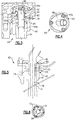
Figure 2 illustrates a view of a portion of a thermal management system of the gas turbine engine ofFigure 1 . -
Figure 3 illustrates a perspective, cutaway view of a metering device of the thermal management system ofFigure 2 . -
Figure 4 illustrates a top-down view of the metering device ofFigure 2 . -
Figure 5 illustrates a schematic cross-sectional view of the metering device ofFigure 2 . -
Figure 6 illustrates a view of an orifice plate of the metering device ofFigure 2 . -
Figure 1 schematically illustrates agas turbine engine 20. Thegas turbine engine 20 is disclosed herein as a two-spool turbofan that generally incorporates afan section 22, acompressor section 24, acombustor section 26 and aturbine section 28. Thecompressor section 24, thecombustor section 26 and theturbine section 28 constitute a core of theengine 20. Alternative engines might include an augmentor section (not shown) among other systems or features. Thefan section 22 drives air along a bypass flowpath while thecompressor section 24 drives air along a core flowpath for compression and communication into thecombustor section 26 then expansion through theturbine section 28. Although depicted as a turbofan gas turbine engine in the disclosed non-limiting embodiment, it should be understood that the concepts described herein are not limited to use with turbofans and the teachings may be applied to other types of turbine engines, including single-spool architectures, three-spool architectures and ground-based turbines that do not include thefan section 22. - The
engine 20 generally includes afirst spool 30 and asecond spool 32 mounted for rotation about an engine central axis A relative to an enginestatic structure 36 viaseveral bearing systems 38. It should be understood thatvarious bearing systems 38 at various locations may alternatively or additionally be provided. - The
first spool 30 generally includes afirst shaft 40 that interconnects afan 42, afirst compressor 44 and afirst turbine 46. Thefirst shaft 40 is connected to thefan 42 through a gear assembly of a fandrive gear system 48 to drive thefan 42 at a lower speed than thefirst spool 30. Thesecond spool 32 includes asecond shaft 50 that interconnects asecond compressor 52 andsecond turbine 54. Thefirst spool 30 runs at a relatively lower pressure than thesecond spool 32. It is to be understood that "low pressure" and "high pressure" or variations thereof as used herein are relative terms indicating that the high pressure is greater than the low pressure. - The
engine 20 also includes amid-turbine section 56, (or mid-turbine frame, "MTF") having a plurality ofairfoil 56a (one shown, here a static vane). Themid-turbine section 56 is located axially between the first turbine 54 (e.g., high pressure turbine, "HPT") and the second turbine 46 (e.g., low pressure turbine , "LPT"). Thus, in this example, theturbine section 28 includes three sections, 46, 54 and 56, which are further considered to be, with no particular implication of the order, first, second and third turbine sections. As can be appreciated, theairfoils 56a orient core gas flow through theturbine section 28 in an axial direction. Aerodynamic loads on theairfoils 56a are transferred to astatic engine case 56b, which represents an outer periphery or outer diameter of the engine core (relative to engine central axis A). - An
annular combustor 58 is arranged between thesecond compressor 52 and thesecond turbine 54. Thefirst shaft 40 and thesecond shaft 50 are concentric and rotate via bearingsystems 38 about the engine central axis A which is collinear with their longitudinal axes. - The core airflow is compressed by the
first compressor 44 then thesecond compressor 52, mixed and burned with fuel in theannular combustor 58, then expanded over thesecond turbine 54 andfirst turbine 46. Thefirst turbine 46 and thesecond turbine 54 rotationally drive, respectively, thefirst spool 30 and thesecond spool 32 in response to the expansion. - The
engine 20 is a high-bypass geared aircraft engine that has a bypass ratio that is greater than about six (6), with an example embodiment being greater than ten (10), the gear assembly of the fandrive gear system 48 is an epicyclic gear train, such as a planetary gear system or other gear system, with a gear reduction ratio of greater than about 2.3:1 and thefirst turbine 46 has a pressure ratio that is greater than about 5. Thefirst turbine 46 pressure ratio is pressure measured prior to inlet offirst turbine 46 as related to the pressure at the outlet of thefirst turbine 46 prior to an exhaust nozzle. Thefirst turbine 46 has a maximum rotor diameter and thefan 42 has a fan diameter such that a ratio of the maximum rotor diameter divided by the fan diameter is less than 0.6. It should be understood, however, that the above parameters are only exemplary. - A significant amount of thrust is provided by the bypass flow B due to the high bypass ratio. The
fan section 22 of theengine 20 is designed for a particular flight condition -- typically cruise at about 0.8 Mach and about 35,000 feet. The flight condition of 0.8 Mach and 35,000 feet, with the engine at its best fuel consumption. To make an accurate comparison of fuel consumption between engines, fuel consumption is reduced to a common denominator, which is applicable to all types and sizes of turbojets and turbofans. The term is thrust specific fuel consumption, or TSFC. This is an engine's fuel consumption in pounds per hour divided by the net thrust. The result is the amount of fuel required to produce one pound of thrust. The TSFC unit is pounds per hour per pounds of thrust (lb/hr/lb Fn). When it is obvious that the reference is to a turbojet or turbofan engine, TSFC is often simply called specific fuel consumption, or SFC. "Low fan pressure ratio" is the pressure ratio across the fan blade alone, without a Fan Exit Guide Vane system. The low fan pressure ratio as disclosed herein according to one non-limiting embodiment is less than about 1.5. "Low corrected fan tip speed" is the actual fan tip speed in feet per second divided by an industry standard temperature correction of [(Tram °R) / (518.7 °R)]0.5. The "Low corrected fan tip speed" as disclosed herein according to one non-limiting embodiment is less than about 1150 feet per second. - As shown schematically in
Figure 1 , theengine 20 can utilize athermal management system 60 to convey relatively cool air, such as from thecompressor section 24, to other, relatively hot components. For example, thethermal management system 60 is configured to receive relatively cool air from thecompressor section 24 to cool airfoils, such as rotatable blades or static vanes, in multiple turbine stages or sub-sections of theturbine section 28, such as in theturbine sections turbine section 56. As can be appreciated, thethermal management system 60 is not limited to use of compressor air or to cooling turbine airfoils. -
Figure 2 shows a magnified view of a portion of thethermal management system 60 at themid-turbine section 56 of theengine 20. As shown, thethermal management system 60 includes ametering device 62 that is located near an outer diameter of the core engine. The outer diameter is represented by thestatic engine case 56b. In the example shown, at least a portion of themetering device 62 is located radially outwards of the outer diameter of the core engine. A portion of themetering device 62 may extend radially inwards of thestatic engine case 56b as well, or theentire metering device 62 can be located radially outwards of thestatic case 56b. For example, at least a portion of themetering device 62 is at the outer diameter. -
Figure 3 shows a perspective, partial cutaway view of themetering device 62.Figure 4 shows a radial view of themetering device 62 according to the view line shown inFigure 2 , andFigure 5 shows another magnified view of themetering device 62. Referring toFigures 2-5 , themetering device 62 includes a T-shapedtube 64 that has atube portion 66 attached at afirst end 66a to anorifice plate 68. Thetube portion 66 is attached at a second,opposed end 66b to anothertube 70 that is arranged coaxially with thetube portion 66. For example, thesecond end 66b of thetube portion 66 is connected in an interference fit with thetube 70. - Referring also to
Figure 6 , theorifice plate 68 includes a plurality oforifices 72 that open into afirst passage 74 and acentral orifice 76 that opens into asecond passage 78. In this example, the plurality oforifices 72 that open into thefirst passage 74 are arranged circumferentially around thecentral orifice 76 that opens into thesecond passage 78. As shown, thecentral orifice 76 is circular and theorifices 72 are non-circular. The disclosed shape and arrangement provides for a compact packaging arrangement, however, in other examples, other shapes could be used as packaging considerations permit. - The
second passage 78 extends through thetube portion 66 of the T-shapedtube 64. Thefirst passage 74 is an annular passage that extends between the periphery of the T-shapedtube 64 and anouter tube 80. Theouter tube 80 is attached to thetube 70. For example, theouter tube 80 is interference fit with thetube 70 or includes threading or a threaded nut portion for mounting on thetube 70. Thefirst passage 74 is thus concentric with thesecond passage 78. Additionally, theouter tube 80 includes a plurality ofpassages 82 that extend along respective axis that are oblique to the axis of thefirst passage 74 and thesecond passage 78. - As shown in
Figure 4 , a fitting 84 is mounted over theorifice plate 68. The fitting 84 includes aport 84a for connecting themetering device 62 with a cooling stream source, such as thecompressor section 24. If connected to thecompressor section 24 to receive bleed air, such connections are known and therefore not described in further detail in this description. - Cooling air is provided through the
thermal management system 60 into theport 84a and to themetering device 62. Themetering device 62 divides the cooling stream into multiple segregated passages, which in the illustrated example include thefirst passage 74 and thesecond passage 78. It is to be appreciated however, that themetering device 62 could alternatively be configured to divide the cooling stream into additional segregated cooling passages. - The
orifice plate 68, including the plurality oforifices 72 and thecentral orifice 76, serve to divide the cooling stream between thefirst passage 74 and thesecond passage 78. For example, the division of the cooling stream is determined by the relative areas of the plurality oforifices 72 in comparison to the area of thecentral orifice 76. Thus, by adjusting the relative sizes of theorifices 72/76, the cooling stream can be divided as desired between thefirst passage 74 and thesecond passage 78 to thus meter respective flows to thefirst passage 74 and thesecond passage 78. The location of theorifice plate 68 near the outer diameter of the core engine can also permit theorifice plate 68 to be relatively easily retrofit into an existing system, and can permit an existingorifice plate 68 to be replaced with a similar or resizedorifice plate 68. Further, theorifice plate 68 is a relatively low-cost component and can be accessed at the outer diameter of the core engine without extensive disassembly of engine components. - The flow through the
first passage 74 and thesecond passage 78 can then be provided to different components of theengine 20. For example, the different components can be a first turbine section and a second turbine section that is located downstream from the first turbine section. In a further example, thefirst passage 74 provides cooling air to themid-turbine section 56 and thesecond passage 78 provides cooling air to thefirst turbine section 46. - The flow of the cooling stream that is conveyed through the
central orifice 76 and into thesecond passage 78 is fed into thetube 70, which extends through theairfoil 56a in themid-turbine section 56. As shown inFigure 2 , thetube 70 extends into an outer diameter of theairfoil 56a, through theairfoil 56a and out of an inner diameter of theairfoil 56a. Thetube 70 terminates at anend 70a in the core engine. For example, the area surrounding theend 70a of thetube 70 may be within atorque box 90 of theengine 20. Thus, the cooling air provided through thetube 70 is fed into the interior of thetorque box 90 and then subsequently fed through feed channels to theturbine section 46, for example. - The portion of the cooling stream that is divided and flows through the
first passage 74 flows between the periphery of thetube portion 66 and theouter tube 80. The cooling air turns and flows through the plurality ofpassages 82 and then around an exterior of theouter tube 80 and into theairfoil 56a. This air serves to purge the interior of theairfoil 56a. For example, the cooling air flowing through the first passage 74a enters at the outer diameter of theairfoil 56a, flows through theairfoil 56a, and exits at the inner diameter of theairfoil 56a. This cooling air may then be bled off through leak paths into the core flow through theengine 20. - The
thermal management system 60 thus provides a design that permits separate metering of multiple flow streams from a single source stream. Separate metering of multiple flow streams from a single source stream provides discrete air to separate engine components, which benefits flow balancing and safeguards flow disruption to priority cavities. The metering orifices can be provided in appropriate numbers and sizes such to segregate the flow according to the needs of the destination component(s). - Additionally, the disclosed example also provide packaging benefits by reducing the number of external feed lines required and reducing or eliminating a need for separate metering for two flow streams (e.g., MTF cavity and LPT rotor cavity). Engine derivatives can also benefit from metering capabilities and packaging benefits. The disclosed arrangement can also be employed to meter and segregate separate flow streams and can be applied in non-gas turbine applications.
- Although a combination of features is shown in the illustrated examples, not all of them need to be combined to realize the benefits of various embodiments of this disclosure. In other words, a system designed according to an embodiment of this disclosure will not necessarily include all of the features shown in any one of the Figures or all of the portions schematically shown in the Figures. Moreover, selected features of one example embodiment may be combined with selected features of other example embodiments.
- The preceding description is exemplary rather than limiting in nature. Variations and modifications to the disclosed examples may become apparent to those skilled in the art that do not necessarily depart from the essence of this disclosure. The scope of legal protection given to this disclosure can only be determined by studying the following claims.
Claims (15)
- A gas turbine engine (20) comprising:a core engine including,a compressor section (24),a combustor (26) in fluid communication with the compressor section (24), anda turbine section (28) in fluid communication with the combustor (26); anda thermal management system (60) operable to receive a cooling stream, the thermal management system (60) including a metering device (62) that is configured to divide the cooling stream between a first passage (74) and a second passage (78) that is concentric with the first passage (74).
- The gas turbine engine (20) as recited in claim 1, wherein the metering device (62) includes a plurality of orifices (72) opening to the first passage (74) and a central orifice (76) opening to the second passage (78).
- The gas turbine engine (20) as recited in claim 2, wherein the plurality of orifices (72) are arranged circumferentially around the central orifice (76).
- The gas turbine engine (20) as recited in any preceding claim, wherein the first passage (74) is an annular passage.
- The gas turbine engine (20) as recited in any preceding claim, wherein the metering device (62) includes a t-shaped tube (64) having a tube portion (66) attached at one end (66a) to an orifice plate (68).
- The gas turbine engine (20) as recited in claim 5, wherein the tube portion (66) is attached at an opposed end (66b) to another tube (70) extending coaxially therewith.
- The gas turbine engine (20) as recited in any preceding claim, wherein the metering device (62) is located near an outer diameter of the core engine.
- The gas turbine engine (20) as recited in any preceding claim, wherein the first passage (74) and the second passage (78) extend into a radially outer end of an airfoil (56a), through the airfoil (56a) and out from a radially inner end of the airfoil (56a).
- A method for dividing a cooling stream in a thermal management system (60) of a gas turbine engine (20), the method comprising:providing a cooling stream into a thermal management system (60) of a gas turbine engine (20);dividing the cooling stream into multiple segregated streams at a location near an outer diameter of a core engine of the gas turbine engine (20); andproviding the multiple segregated streams to different components of the engine (20), optionally wherein the different components are a first turbine section (54) and a second turbine section (46) that is located downstream from the first turbine section (54).
- A gas turbine engine (20) comprising:a core engine including,a compressor section (24),a combustor (26) in fluid communication with the compressor section (24), anda turbine section (28) in fluid communication with the combustor (26); anda thermal management system (60) configured to receive a cooling stream, the thermal management system (60) including a metering device (62) located near an outer diameter of the core engine, the metering device being configured to divide the cooling stream into multiple segregated passages (74, 78).
- The gas turbine engine (20) as recited in claim 10, wherein the thermal management system (60) is connected to the compressor section (24) and the cooling stream is bleed air.
- The gas turbine engine (20) as recited in claim 10 or 11, wherein the metering device (62) is located at the outer diameter of the turbine section (28).
- The gas turbine engine (20) as recited in claim 10, 11 or 12, wherein the turbine section (28) includes a first turbine section (54) and a second turbine section (46) downstream of the first turbine section (54), and the outer diameter is of the first turbine section (54), optionally wherein at least one of the multiple segregated passages (74, 78) leads to the second turbine section (46).
- The gas turbine engine (20) as recited in any of claims 10 to 13, wherein:the multiple segregated passages (74, 78) include a first passage (74) and a second passage (78) that is concentric with the first passage (74); and/orat least a portion of the metering device (62) is located radially outwards of the outer diameter relative to the central axis (A) of the core engine.
- The gas turbine engine (20) as recited in any of claims 10 to 14, wherein:the multiple segregated passages (74, 78) extend into a radially outer end of an airfoil (56a), through the airfoil (56a) and out from a radially inner end of the airfoil (56a); and/orthe multiple segregated passages (74, 78) extend through a or the airfoil (56a).
Applications Claiming Priority (3)
| Application Number | Priority Date | Filing Date | Title |
|---|---|---|---|
| US201261707534P | 2012-09-28 | 2012-09-28 | |
| EP13842149.0A EP2900968B1 (en) | 2012-09-28 | 2013-03-01 | Split-zone flow metering t-tube |
| PCT/US2013/028537 WO2014051672A1 (en) | 2012-09-28 | 2013-03-01 | Split-zone flow metering t-tube |
Related Parent Applications (1)
| Application Number | Title | Priority Date | Filing Date |
|---|---|---|---|
| EP13842149.0A Division EP2900968B1 (en) | 2012-09-28 | 2013-03-01 | Split-zone flow metering t-tube |
Publications (2)
| Publication Number | Publication Date |
|---|---|
| EP3456943A1 true EP3456943A1 (en) | 2019-03-20 |
| EP3456943B1 EP3456943B1 (en) | 2021-08-04 |
Family
ID=50388834
Family Applications (2)
| Application Number | Title | Priority Date | Filing Date |
|---|---|---|---|
| EP13842149.0A Active EP2900968B1 (en) | 2012-09-28 | 2013-03-01 | Split-zone flow metering t-tube |
| EP18202618.7A Active EP3456943B1 (en) | 2012-09-28 | 2013-03-01 | Split-zone flow metering t-tube |
Family Applications Before (1)
| Application Number | Title | Priority Date | Filing Date |
|---|---|---|---|
| EP13842149.0A Active EP2900968B1 (en) | 2012-09-28 | 2013-03-01 | Split-zone flow metering t-tube |
Country Status (3)
| Country | Link |
|---|---|
| US (2) | US9863319B2 (en) |
| EP (2) | EP2900968B1 (en) |
| WO (1) | WO2014051672A1 (en) |
Families Citing this family (12)
| Publication number | Priority date | Publication date | Assignee | Title |
|---|---|---|---|---|
| CN106255806B (en) * | 2014-05-08 | 2019-05-31 | 西门子股份公司 | Turbine assembly and corresponding method of operation |
| US10443498B2 (en) | 2014-08-15 | 2019-10-15 | United Technologies Corporation | Gas turbine engine cooling fluid metering system |
| US10047623B2 (en) | 2014-12-17 | 2018-08-14 | United Technologies Corporation | Compliant seal assembly and method of operating |
| US10309308B2 (en) * | 2015-01-16 | 2019-06-04 | United Technologies Corporation | Cooling passages for a mid-turbine frame |
| US9885254B2 (en) * | 2015-04-24 | 2018-02-06 | United Technologies Corporation | Mid turbine frame including a sealed torque box |
| US10247035B2 (en) | 2015-07-24 | 2019-04-02 | Pratt & Whitney Canada Corp. | Spoke locking architecture |
| CA2936180C (en) * | 2015-07-24 | 2025-05-06 | Pratt & Whitney Canada Corp. | Multiple spoke cooling system and method |
| US10443449B2 (en) | 2015-07-24 | 2019-10-15 | Pratt & Whitney Canada Corp. | Spoke mounting arrangement |
| US20180128206A1 (en) * | 2016-11-09 | 2018-05-10 | General Electric Company | Gas turbine engine |
| US11421627B2 (en) * | 2017-02-22 | 2022-08-23 | General Electric Company | Aircraft and direct drive engine under wing installation |
| US11181004B2 (en) * | 2020-02-07 | 2021-11-23 | Raytheon Technologies Corporation | Confinement of a rope seal about a passage using a backing plate |
| FR3110201B1 (en) * | 2020-05-15 | 2022-04-08 | Safran Aircraft Engines | Turbomachine exhaust housing |
Citations (5)
| Publication number | Priority date | Publication date | Assignee | Title |
|---|---|---|---|---|
| FR1325291A (en) * | 1962-05-28 | 1963-04-26 | Rolls Royce | Bearing support structure for turbojet |
| US3369366A (en) * | 1964-05-28 | 1968-02-20 | Gen Electric | Jet engine support structure |
| US4321007A (en) * | 1979-12-21 | 1982-03-23 | United Technologies Corporation | Outer case cooling for a turbine intermediate case |
| WO2013067361A1 (en) * | 2011-11-04 | 2013-05-10 | United Technologies Corporation | Tie-rod nut including a nut flange with a plurality of mounting apertures |
| WO2014008129A1 (en) * | 2012-07-02 | 2014-01-09 | United Technologies Corporation | Cooling apparatus for a mid-turbine frame |
Family Cites Families (98)
| Publication number | Priority date | Publication date | Assignee | Title |
|---|---|---|---|---|
| US2258792A (en) | 1941-04-12 | 1941-10-14 | Westinghouse Electric & Mfg Co | Turbine blading |
| US3021731A (en) | 1951-11-10 | 1962-02-20 | Wilhelm G Stoeckicht | Planetary gear transmission |
| US2936655A (en) | 1955-11-04 | 1960-05-17 | Gen Motors Corp | Self-aligning planetary gearing |
| US3034298A (en) * | 1958-06-12 | 1962-05-15 | Gen Motors Corp | Turbine cooling system |
| US3108767A (en) | 1960-03-14 | 1963-10-29 | Rolls Royce | By-pass gas turbine engine with air bleed means |
| US3194487A (en) | 1963-06-04 | 1965-07-13 | United Aircraft Corp | Noise abatement method and apparatus |
| US3287906A (en) | 1965-07-20 | 1966-11-29 | Gen Motors Corp | Cooled gas turbine vanes |
| US3352178A (en) | 1965-11-15 | 1967-11-14 | Gen Motors Corp | Planetary gearing |
| US3412560A (en) | 1966-08-03 | 1968-11-26 | Gen Motors Corp | Jet propulsion engine with cooled combustion chamber, fuel heater, and induced air-flow |
| BE755567A (en) * | 1969-12-01 | 1971-02-15 | Gen Electric | FIXED VANE STRUCTURE, FOR GAS TURBINE ENGINE AND ASSOCIATED TEMPERATURE ADJUSTMENT ARRANGEMENT |
| US3664612A (en) | 1969-12-22 | 1972-05-23 | Boeing Co | Aircraft engine variable highlight inlet |
| GB1350431A (en) | 1971-01-08 | 1974-04-18 | Secr Defence | Gearing |
| US3892358A (en) | 1971-03-17 | 1975-07-01 | Gen Electric | Nozzle seal |
| US3747343A (en) | 1972-02-10 | 1973-07-24 | United Aircraft Corp | Low noise prop-fan |
| GB1418905A (en) | 1972-05-09 | 1975-12-24 | Rolls Royce | Gas turbine engines |
| US3988889A (en) | 1974-02-25 | 1976-11-02 | General Electric Company | Cowling arrangement for a turbofan engine |
| US3932058A (en) | 1974-06-07 | 1976-01-13 | United Technologies Corporation | Control system for variable pitch fan propulsor |
| US3935558A (en) | 1974-12-11 | 1976-01-27 | United Technologies Corporation | Surge detector for turbine engines |
| US4130872A (en) | 1975-10-10 | 1978-12-19 | The United States Of America As Represented By The Secretary Of The Air Force | Method and system of controlling a jet engine for avoiding engine surge |
| GB1516041A (en) | 1977-02-14 | 1978-06-28 | Secr Defence | Multistage axial flow compressor stators |
| GB2041090A (en) | 1979-01-31 | 1980-09-03 | Rolls Royce | By-pass gas turbine engines |
| US4284174A (en) | 1979-04-18 | 1981-08-18 | Avco Corporation | Emergency oil/mist system |
| US4289360A (en) | 1979-08-23 | 1981-09-15 | General Electric Company | Bearing damper system |
| DE2940446C2 (en) | 1979-10-05 | 1982-07-08 | B. Braun Melsungen Ag, 3508 Melsungen | Cultivation of animal cells in suspension and monolayer cultures in fermentation vessels |
| US4478551A (en) | 1981-12-08 | 1984-10-23 | United Technologies Corporation | Turbine exhaust case design |
| US4882902A (en) * | 1986-04-30 | 1989-11-28 | General Electric Company | Turbine cooling air transferring apparatus |
| US4696156A (en) | 1986-06-03 | 1987-09-29 | United Technologies Corporation | Fuel and oil heat management system for a gas turbine engine |
| GB2207465B (en) * | 1987-07-18 | 1992-02-19 | Rolls Royce Plc | A compressor and air bleed arrangement |
| US4989403A (en) | 1988-05-23 | 1991-02-05 | Sundstrand Corporation | Surge protected gas turbine engine for providing variable bleed air flow |
| US4979362A (en) | 1989-05-17 | 1990-12-25 | Sundstrand Corporation | Aircraft engine starting and emergency power generating system |
| FR2656657A1 (en) * | 1989-12-28 | 1991-07-05 | Snecma | AIR COOLED TURBOMACHINE AND METHOD FOR COOLING THE SAME. |
| US5141400A (en) | 1991-01-25 | 1992-08-25 | General Electric Company | Wide chord fan blade |
| US5102379A (en) | 1991-03-25 | 1992-04-07 | United Technologies Corporation | Journal bearing arrangement |
| GB2263946A (en) | 1992-02-04 | 1993-08-11 | Bmw Rolls Royce Gmbh | An arrangement for supplying cooling air to a gas turbine casing. |
| US5305616A (en) * | 1992-03-23 | 1994-04-26 | General Electric Company | Gas turbine engine cooling system |
| US5317877A (en) | 1992-08-03 | 1994-06-07 | General Electric Company | Intercooled turbine blade cooling air feed system |
| US5447411A (en) | 1993-06-10 | 1995-09-05 | Martin Marietta Corporation | Light weight fan blade containment system |
| US5466198A (en) | 1993-06-11 | 1995-11-14 | United Technologies Corporation | Geared drive system for a bladed propulsor |
| US5361580A (en) | 1993-06-18 | 1994-11-08 | General Electric Company | Gas turbine engine rotor support system |
| US5524847A (en) | 1993-09-07 | 1996-06-11 | United Technologies Corporation | Nacelle and mounting arrangement for an aircraft engine |
| RU2082824C1 (en) | 1994-03-10 | 1997-06-27 | Московский государственный авиационный институт (технический университет) | Method of protection of heat-resistant material from effect of high-rapid gaseous flow of corrosive media (variants) |
| US5433674A (en) | 1994-04-12 | 1995-07-18 | United Technologies Corporation | Coupling system for a planetary gear train |
| US5778659A (en) | 1994-10-20 | 1998-07-14 | United Technologies Corporation | Variable area fan exhaust nozzle having mechanically separate sleeve and thrust reverser actuation systems |
| WO1997000381A1 (en) | 1994-12-14 | 1997-01-03 | United Technologies Corporation | Compressor stall and surge control using airflow asymmetry measurement |
| US5645397A (en) * | 1995-10-10 | 1997-07-08 | United Technologies Corporation | Turbine vane assembly with multiple passage cooled vanes |
| JP2969075B2 (en) | 1996-02-26 | 1999-11-02 | ジャパンゴアテックス株式会社 | Degassing device |
| US5634767A (en) | 1996-03-29 | 1997-06-03 | General Electric Company | Turbine frame having spindle mounted liner |
| US5857836A (en) | 1996-09-10 | 1999-01-12 | Aerodyne Research, Inc. | Evaporatively cooled rotor for a gas turbine engine |
| US5975841A (en) | 1997-10-03 | 1999-11-02 | Thermal Corp. | Heat pipe cooling for turbine stators |
| US5985470A (en) | 1998-03-16 | 1999-11-16 | General Electric Company | Thermal/environmental barrier coating system for silicon-based materials |
| US6672072B1 (en) | 1998-08-17 | 2004-01-06 | General Electric Company | Pressure boosted compressor cooling system |
| US6517341B1 (en) | 1999-02-26 | 2003-02-11 | General Electric Company | Method to prevent recession loss of silica and silicon-containing materials in combustion gas environments |
| US6410148B1 (en) | 1999-04-15 | 2002-06-25 | General Electric Co. | Silicon based substrate with environmental/ thermal barrier layer |
| ITMI991208A1 (en) * | 1999-05-31 | 2000-12-01 | Nuovo Pignone Spa | DEVICE FOR THE POSITIONING OF NOZZLES OF A STATIC STAGE AND FOR THE COOLING OF ROTOR DISCS IN GAS TURBINES |
| US6315815B1 (en) | 1999-12-16 | 2001-11-13 | United Technologies Corporation | Membrane based fuel deoxygenator |
| US6223616B1 (en) | 1999-12-22 | 2001-05-01 | United Technologies Corporation | Star gear system with lubrication circuit and lubrication method therefor |
| US6318070B1 (en) | 2000-03-03 | 2001-11-20 | United Technologies Corporation | Variable area nozzle for gas turbine engines driven by shape memory alloy actuators |
| US6444335B1 (en) | 2000-04-06 | 2002-09-03 | General Electric Company | Thermal/environmental barrier coating for silicon-containing materials |
| DE10019437A1 (en) | 2000-04-19 | 2001-12-20 | Rolls Royce Deutschland | Method and device for cooling the housings of turbines of jet engines |
| EP1780387A3 (en) | 2000-09-05 | 2007-07-18 | Sudarshan Paul Dev | Nested core gas turbine engine |
| US6708482B2 (en) | 2001-11-29 | 2004-03-23 | General Electric Company | Aircraft engine with inter-turbine engine frame |
| US6607165B1 (en) | 2002-06-28 | 2003-08-19 | General Electric Company | Aircraft engine mount with single thrust link |
| US6814541B2 (en) | 2002-10-07 | 2004-11-09 | General Electric Company | Jet aircraft fan case containment design |
| US7021042B2 (en) | 2002-12-13 | 2006-04-04 | United Technologies Corporation | Geartrain coupling for a turbofan engine |
| US6709492B1 (en) | 2003-04-04 | 2004-03-23 | United Technologies Corporation | Planar membrane deoxygenator |
| US7093419B2 (en) | 2003-07-02 | 2006-08-22 | General Electric Company | Methods and apparatus for operating gas turbine engine combustors |
| DE102004016246A1 (en) | 2004-04-02 | 2005-10-20 | Mtu Aero Engines Gmbh | Turbine, in particular low-pressure turbine, a gas turbine, in particular an aircraft engine |
| US7328580B2 (en) | 2004-06-23 | 2008-02-12 | General Electric Company | Chevron film cooled wall |
| US7287384B2 (en) | 2004-12-13 | 2007-10-30 | Pratt & Whitney Canada Corp. | Bearing chamber pressurization system |
| GB0506685D0 (en) | 2005-04-01 | 2005-05-11 | Hopkins David R | A design to increase and smoothly improve the throughput of fluid (air or gas) through the inlet fan (or fans) of an aero-engine system |
| US7374403B2 (en) | 2005-04-07 | 2008-05-20 | General Electric Company | Low solidity turbofan |
| EP1928952B1 (en) | 2005-09-28 | 2014-07-09 | Entrotech Composites, LLC. | Braid-reinforced composites and processes for their preparation |
| US7591754B2 (en) | 2006-03-22 | 2009-09-22 | United Technologies Corporation | Epicyclic gear train integral sun gear coupling design |
| BE1017135A3 (en) | 2006-05-11 | 2008-03-04 | Hansen Transmissions Int | A GEARBOX FOR A WIND TURBINE. |
| US20080003096A1 (en) | 2006-06-29 | 2008-01-03 | United Technologies Corporation | High coverage cooling hole shape |
| US7926260B2 (en) | 2006-07-05 | 2011-04-19 | United Technologies Corporation | Flexible shaft for gas turbine engine |
| US8585538B2 (en) | 2006-07-05 | 2013-11-19 | United Technologies Corporation | Coupling system for a star gear train in a gas turbine engine |
| US7632064B2 (en) | 2006-09-01 | 2009-12-15 | United Technologies Corporation | Variable geometry guide vane for a gas turbine engine |
| US7662059B2 (en) | 2006-10-18 | 2010-02-16 | United Technologies Corporation | Lubrication of windmilling journal bearings |
| US7743613B2 (en) * | 2006-11-10 | 2010-06-29 | General Electric Company | Compound turbine cooled engine |
| US8020665B2 (en) | 2006-11-22 | 2011-09-20 | United Technologies Corporation | Lubrication system with extended emergency operability |
| US8017188B2 (en) | 2007-04-17 | 2011-09-13 | General Electric Company | Methods of making articles having toughened and untoughened regions |
| US7950237B2 (en) | 2007-06-25 | 2011-05-31 | United Technologies Corporation | Managing spool bearing load using variable area flow nozzle |
| US20120124964A1 (en) | 2007-07-27 | 2012-05-24 | Hasel Karl L | Gas turbine engine with improved fuel efficiency |
| US8256707B2 (en) | 2007-08-01 | 2012-09-04 | United Technologies Corporation | Engine mounting configuration for a turbofan gas turbine engine |
| US8128348B2 (en) * | 2007-09-26 | 2012-03-06 | United Technologies Corporation | Segmented cooling air cavity for turbine component |
| US8205432B2 (en) | 2007-10-03 | 2012-06-26 | United Technologies Corporation | Epicyclic gear train for turbo fan engine |
| US8128021B2 (en) | 2008-06-02 | 2012-03-06 | United Technologies Corporation | Engine mount system for a turbofan gas turbine engine |
| DE102008028987A1 (en) | 2008-06-20 | 2009-12-24 | Rolls-Royce Deutschland Ltd & Co Kg | Turboprop engine with a device for generating a cooling air flow |
| US7997868B1 (en) | 2008-11-18 | 2011-08-16 | Florida Turbine Technologies, Inc. | Film cooling hole for turbine airfoil |
| US8307626B2 (en) | 2009-02-26 | 2012-11-13 | United Technologies Corporation | Auxiliary pump system for fan drive gear system |
| US8181441B2 (en) | 2009-02-27 | 2012-05-22 | United Technologies Corporation | Controlled fan stream flow bypass |
| US8172716B2 (en) | 2009-06-25 | 2012-05-08 | United Technologies Corporation | Epicyclic gear system with superfinished journal bearing |
| US8453464B2 (en) | 2009-10-01 | 2013-06-04 | Pratt & Whitney Canada Corp. | Air metering device for gas turbine engine |
| US9170616B2 (en) | 2009-12-31 | 2015-10-27 | Intel Corporation | Quiet system cooling using coupled optimization between integrated micro porous absorbers and rotors |
| US8905713B2 (en) | 2010-05-28 | 2014-12-09 | General Electric Company | Articles which include chevron film cooling holes, and related processes |
| GB201015028D0 (en) | 2010-09-10 | 2010-10-20 | Rolls Royce Plc | Gas turbine engine |
| US20120070271A1 (en) | 2010-09-21 | 2012-03-22 | Urban Justin R | Gas turbine engine with bleed duct for minimum reduction of bleed flow and minimum rejection of hail during hail ingestion events |
-
2013
- 2013-03-01 US US14/429,167 patent/US9863319B2/en active Active
- 2013-03-01 EP EP13842149.0A patent/EP2900968B1/en active Active
- 2013-03-01 EP EP18202618.7A patent/EP3456943B1/en active Active
- 2013-03-01 WO PCT/US2013/028537 patent/WO2014051672A1/en not_active Ceased
-
2016
- 2016-04-21 US US15/134,653 patent/US10808617B2/en active Active
Patent Citations (5)
| Publication number | Priority date | Publication date | Assignee | Title |
|---|---|---|---|---|
| FR1325291A (en) * | 1962-05-28 | 1963-04-26 | Rolls Royce | Bearing support structure for turbojet |
| US3369366A (en) * | 1964-05-28 | 1968-02-20 | Gen Electric | Jet engine support structure |
| US4321007A (en) * | 1979-12-21 | 1982-03-23 | United Technologies Corporation | Outer case cooling for a turbine intermediate case |
| WO2013067361A1 (en) * | 2011-11-04 | 2013-05-10 | United Technologies Corporation | Tie-rod nut including a nut flange with a plurality of mounting apertures |
| WO2014008129A1 (en) * | 2012-07-02 | 2014-01-09 | United Technologies Corporation | Cooling apparatus for a mid-turbine frame |
Also Published As
| Publication number | Publication date |
|---|---|
| US9863319B2 (en) | 2018-01-09 |
| US20150233295A1 (en) | 2015-08-20 |
| US20170342904A1 (en) | 2017-11-30 |
| EP2900968A1 (en) | 2015-08-05 |
| US10808617B2 (en) | 2020-10-20 |
| EP3456943B1 (en) | 2021-08-04 |
| EP2900968A4 (en) | 2016-05-25 |
| EP2900968B1 (en) | 2018-10-31 |
| WO2014051672A1 (en) | 2014-04-03 |
Similar Documents
| Publication | Publication Date | Title |
|---|---|---|
| EP3456943B1 (en) | Split-zone flow metering t-tube | |
| EP3085923B1 (en) | Cooling air intercooling with dual pass heat exchanger | |
| EP3348803B1 (en) | Engine mid-turbine frame transfer tube for low pressure turbine case cooling | |
| EP2900998B1 (en) | Buffer airflow to bearing compartment | |
| US9188009B2 (en) | Bore cavity thermal conditioning system | |
| EP2935804B1 (en) | Gas turbine engine inner case including non-symmetrical bleed slots | |
| EP2904231B1 (en) | Gas turbine engine including bleed system coupled to upstream and downstream locations of compressor and a corresponding method | |
| EP3060760B1 (en) | Airfoil with skin core cooling | |
| EP2901082B1 (en) | Inner diffuser case struts for a combustor of a gas turbine engine | |
| EP3330515B1 (en) | Gas turbine engine | |
| EP3299791B1 (en) | Gas turbine engine with heat exchanger diagnostics | |
| EP3219959B1 (en) | Intercooled cooling air using existing heat exchanger | |
| EP3064745B1 (en) | Diversion of air to provide cooling air for gas turbine engine | |
| EP3181869B1 (en) | Compressor core inner diameter cooling | |
| EP3358152B1 (en) | External mixing chamber for a gas turbine engine with cooled turbine cooling air | |
| US10184354B2 (en) | Windback heat shield | |
| EP3179034B1 (en) | Multi-source turbine cooling air |
Legal Events
| Date | Code | Title | Description |
|---|---|---|---|
| PUAI | Public reference made under article 153(3) epc to a published international application that has entered the european phase |
Free format text: ORIGINAL CODE: 0009012 |
|
| STAA | Information on the status of an ep patent application or granted ep patent |
Free format text: STATUS: THE APPLICATION HAS BEEN PUBLISHED |
|
| AC | Divisional application: reference to earlier application |
Ref document number: 2900968 Country of ref document: EP Kind code of ref document: P |
|
| AK | Designated contracting states |
Kind code of ref document: A1 Designated state(s): AL AT BE BG CH CY CZ DE DK EE ES FI FR GB GR HR HU IE IS IT LI LT LU LV MC MK MT NL NO PL PT RO RS SE SI SK SM TR |
|
| AX | Request for extension of the european patent |
Extension state: BA ME |
|
| STAA | Information on the status of an ep patent application or granted ep patent |
Free format text: STATUS: REQUEST FOR EXAMINATION WAS MADE |
|
| 17P | Request for examination filed |
Effective date: 20190920 |
|
| RBV | Designated contracting states (corrected) |
Designated state(s): AL AT BE BG CH CY CZ DE DK EE ES FI FR GB GR HR HU IE IS IT LI LT LU LV MC MK MT NL NO PL PT RO RS SE SI SK SM TR |
|
| GRAP | Despatch of communication of intention to grant a patent |
Free format text: ORIGINAL CODE: EPIDOSNIGR1 |
|
| STAA | Information on the status of an ep patent application or granted ep patent |
Free format text: STATUS: GRANT OF PATENT IS INTENDED |
|
| INTG | Intention to grant announced |
Effective date: 20210218 |
|
| RAP1 | Party data changed (applicant data changed or rights of an application transferred) |
Owner name: RAYTHEON TECHNOLOGIES CORPORATION |
|
| GRAS | Grant fee paid |
Free format text: ORIGINAL CODE: EPIDOSNIGR3 |
|
| GRAA | (expected) grant |
Free format text: ORIGINAL CODE: 0009210 |
|
| STAA | Information on the status of an ep patent application or granted ep patent |
Free format text: STATUS: THE PATENT HAS BEEN GRANTED |
|
| AC | Divisional application: reference to earlier application |
Ref document number: 2900968 Country of ref document: EP Kind code of ref document: P |
|
| AK | Designated contracting states |
Kind code of ref document: B1 Designated state(s): AL AT BE BG CH CY CZ DE DK EE ES FI FR GB GR HR HU IE IS IT LI LT LU LV MC MK MT NL NO PL PT RO RS SE SI SK SM TR |
|
| REG | Reference to a national code |
Ref country code: GB Ref legal event code: FG4D |
|
| REG | Reference to a national code |
Ref country code: AT Ref legal event code: REF Ref document number: 1417206 Country of ref document: AT Kind code of ref document: T Effective date: 20210815 |
|
| REG | Reference to a national code |
Ref country code: CH Ref legal event code: EP |
|
| REG | Reference to a national code |
Ref country code: DE Ref legal event code: R096 Ref document number: 602013078704 Country of ref document: DE |
|
| REG | Reference to a national code |
Ref country code: IE Ref legal event code: FG4D |
|
| REG | Reference to a national code |
Ref country code: LT Ref legal event code: MG9D |
|
| REG | Reference to a national code |
Ref country code: NL Ref legal event code: MP Effective date: 20210804 |
|
| REG | Reference to a national code |
Ref country code: AT Ref legal event code: MK05 Ref document number: 1417206 Country of ref document: AT Kind code of ref document: T Effective date: 20210804 |
|
| PG25 | Lapsed in a contracting state [announced via postgrant information from national office to epo] |
Ref country code: RS Free format text: LAPSE BECAUSE OF FAILURE TO SUBMIT A TRANSLATION OF THE DESCRIPTION OR TO PAY THE FEE WITHIN THE PRESCRIBED TIME-LIMIT Effective date: 20210804 Ref country code: SE Free format text: LAPSE BECAUSE OF FAILURE TO SUBMIT A TRANSLATION OF THE DESCRIPTION OR TO PAY THE FEE WITHIN THE PRESCRIBED TIME-LIMIT Effective date: 20210804 Ref country code: HR Free format text: LAPSE BECAUSE OF FAILURE TO SUBMIT A TRANSLATION OF THE DESCRIPTION OR TO PAY THE FEE WITHIN THE PRESCRIBED TIME-LIMIT Effective date: 20210804 Ref country code: FI Free format text: LAPSE BECAUSE OF FAILURE TO SUBMIT A TRANSLATION OF THE DESCRIPTION OR TO PAY THE FEE WITHIN THE PRESCRIBED TIME-LIMIT Effective date: 20210804 Ref country code: ES Free format text: LAPSE BECAUSE OF FAILURE TO SUBMIT A TRANSLATION OF THE DESCRIPTION OR TO PAY THE FEE WITHIN THE PRESCRIBED TIME-LIMIT Effective date: 20210804 Ref country code: LT Free format text: LAPSE BECAUSE OF FAILURE TO SUBMIT A TRANSLATION OF THE DESCRIPTION OR TO PAY THE FEE WITHIN THE PRESCRIBED TIME-LIMIT Effective date: 20210804 Ref country code: BG Free format text: LAPSE BECAUSE OF FAILURE TO SUBMIT A TRANSLATION OF THE DESCRIPTION OR TO PAY THE FEE WITHIN THE PRESCRIBED TIME-LIMIT Effective date: 20211104 Ref country code: AT Free format text: LAPSE BECAUSE OF FAILURE TO SUBMIT A TRANSLATION OF THE DESCRIPTION OR TO PAY THE FEE WITHIN THE PRESCRIBED TIME-LIMIT Effective date: 20210804 Ref country code: NO Free format text: LAPSE BECAUSE OF FAILURE TO SUBMIT A TRANSLATION OF THE DESCRIPTION OR TO PAY THE FEE WITHIN THE PRESCRIBED TIME-LIMIT Effective date: 20211104 Ref country code: PT Free format text: LAPSE BECAUSE OF FAILURE TO SUBMIT A TRANSLATION OF THE DESCRIPTION OR TO PAY THE FEE WITHIN THE PRESCRIBED TIME-LIMIT Effective date: 20211206 |
|
| PG25 | Lapsed in a contracting state [announced via postgrant information from national office to epo] |
Ref country code: PL Free format text: LAPSE BECAUSE OF FAILURE TO SUBMIT A TRANSLATION OF THE DESCRIPTION OR TO PAY THE FEE WITHIN THE PRESCRIBED TIME-LIMIT Effective date: 20210804 Ref country code: LV Free format text: LAPSE BECAUSE OF FAILURE TO SUBMIT A TRANSLATION OF THE DESCRIPTION OR TO PAY THE FEE WITHIN THE PRESCRIBED TIME-LIMIT Effective date: 20210804 Ref country code: GR Free format text: LAPSE BECAUSE OF FAILURE TO SUBMIT A TRANSLATION OF THE DESCRIPTION OR TO PAY THE FEE WITHIN THE PRESCRIBED TIME-LIMIT Effective date: 20211105 |
|
| PG25 | Lapsed in a contracting state [announced via postgrant information from national office to epo] |
Ref country code: NL Free format text: LAPSE BECAUSE OF FAILURE TO SUBMIT A TRANSLATION OF THE DESCRIPTION OR TO PAY THE FEE WITHIN THE PRESCRIBED TIME-LIMIT Effective date: 20210804 |
|
| PG25 | Lapsed in a contracting state [announced via postgrant information from national office to epo] |
Ref country code: DK Free format text: LAPSE BECAUSE OF FAILURE TO SUBMIT A TRANSLATION OF THE DESCRIPTION OR TO PAY THE FEE WITHIN THE PRESCRIBED TIME-LIMIT Effective date: 20210804 |
|
| REG | Reference to a national code |
Ref country code: DE Ref legal event code: R097 Ref document number: 602013078704 Country of ref document: DE |
|
| PG25 | Lapsed in a contracting state [announced via postgrant information from national office to epo] |
Ref country code: SM Free format text: LAPSE BECAUSE OF FAILURE TO SUBMIT A TRANSLATION OF THE DESCRIPTION OR TO PAY THE FEE WITHIN THE PRESCRIBED TIME-LIMIT Effective date: 20210804 Ref country code: SK Free format text: LAPSE BECAUSE OF FAILURE TO SUBMIT A TRANSLATION OF THE DESCRIPTION OR TO PAY THE FEE WITHIN THE PRESCRIBED TIME-LIMIT Effective date: 20210804 Ref country code: RO Free format text: LAPSE BECAUSE OF FAILURE TO SUBMIT A TRANSLATION OF THE DESCRIPTION OR TO PAY THE FEE WITHIN THE PRESCRIBED TIME-LIMIT Effective date: 20210804 Ref country code: EE Free format text: LAPSE BECAUSE OF FAILURE TO SUBMIT A TRANSLATION OF THE DESCRIPTION OR TO PAY THE FEE WITHIN THE PRESCRIBED TIME-LIMIT Effective date: 20210804 Ref country code: CZ Free format text: LAPSE BECAUSE OF FAILURE TO SUBMIT A TRANSLATION OF THE DESCRIPTION OR TO PAY THE FEE WITHIN THE PRESCRIBED TIME-LIMIT Effective date: 20210804 Ref country code: AL Free format text: LAPSE BECAUSE OF FAILURE TO SUBMIT A TRANSLATION OF THE DESCRIPTION OR TO PAY THE FEE WITHIN THE PRESCRIBED TIME-LIMIT Effective date: 20210804 |
|
| PLBE | No opposition filed within time limit |
Free format text: ORIGINAL CODE: 0009261 |
|
| STAA | Information on the status of an ep patent application or granted ep patent |
Free format text: STATUS: NO OPPOSITION FILED WITHIN TIME LIMIT |
|
| 26N | No opposition filed |
Effective date: 20220506 |
|
| PG25 | Lapsed in a contracting state [announced via postgrant information from national office to epo] |
Ref country code: IT Free format text: LAPSE BECAUSE OF FAILURE TO SUBMIT A TRANSLATION OF THE DESCRIPTION OR TO PAY THE FEE WITHIN THE PRESCRIBED TIME-LIMIT Effective date: 20210804 |
|
| PG25 | Lapsed in a contracting state [announced via postgrant information from national office to epo] |
Ref country code: SI Free format text: LAPSE BECAUSE OF FAILURE TO SUBMIT A TRANSLATION OF THE DESCRIPTION OR TO PAY THE FEE WITHIN THE PRESCRIBED TIME-LIMIT Effective date: 20210804 |
|
| PG25 | Lapsed in a contracting state [announced via postgrant information from national office to epo] |
Ref country code: MC Free format text: LAPSE BECAUSE OF FAILURE TO SUBMIT A TRANSLATION OF THE DESCRIPTION OR TO PAY THE FEE WITHIN THE PRESCRIBED TIME-LIMIT Effective date: 20210804 |
|
| REG | Reference to a national code |
Ref country code: CH Ref legal event code: PL |
|
| REG | Reference to a national code |
Ref country code: BE Ref legal event code: MM Effective date: 20220331 |
|
| PG25 | Lapsed in a contracting state [announced via postgrant information from national office to epo] |
Ref country code: LU Free format text: LAPSE BECAUSE OF NON-PAYMENT OF DUE FEES Effective date: 20220301 Ref country code: LI Free format text: LAPSE BECAUSE OF NON-PAYMENT OF DUE FEES Effective date: 20220331 Ref country code: IE Free format text: LAPSE BECAUSE OF NON-PAYMENT OF DUE FEES Effective date: 20220301 Ref country code: CH Free format text: LAPSE BECAUSE OF NON-PAYMENT OF DUE FEES Effective date: 20220331 |
|
| PG25 | Lapsed in a contracting state [announced via postgrant information from national office to epo] |
Ref country code: BE Free format text: LAPSE BECAUSE OF NON-PAYMENT OF DUE FEES Effective date: 20220331 |
|
| P01 | Opt-out of the competence of the unified patent court (upc) registered |
Effective date: 20230521 |
|
| PG25 | Lapsed in a contracting state [announced via postgrant information from national office to epo] |
Ref country code: HU Free format text: LAPSE BECAUSE OF FAILURE TO SUBMIT A TRANSLATION OF THE DESCRIPTION OR TO PAY THE FEE WITHIN THE PRESCRIBED TIME-LIMIT; INVALID AB INITIO Effective date: 20130301 |
|
| PG25 | Lapsed in a contracting state [announced via postgrant information from national office to epo] |
Ref country code: MK Free format text: LAPSE BECAUSE OF FAILURE TO SUBMIT A TRANSLATION OF THE DESCRIPTION OR TO PAY THE FEE WITHIN THE PRESCRIBED TIME-LIMIT Effective date: 20210804 Ref country code: CY Free format text: LAPSE BECAUSE OF FAILURE TO SUBMIT A TRANSLATION OF THE DESCRIPTION OR TO PAY THE FEE WITHIN THE PRESCRIBED TIME-LIMIT Effective date: 20210804 |
|
| PG25 | Lapsed in a contracting state [announced via postgrant information from national office to epo] |
Ref country code: MT Free format text: LAPSE BECAUSE OF FAILURE TO SUBMIT A TRANSLATION OF THE DESCRIPTION OR TO PAY THE FEE WITHIN THE PRESCRIBED TIME-LIMIT Effective date: 20210804 |
|
| REG | Reference to a national code |
Ref country code: DE Ref legal event code: R081 Ref document number: 602013078704 Country of ref document: DE Owner name: RTX CORPORATION (N.D.GES.D. STAATES DELAWARE),, US Free format text: FORMER OWNER: RAYTHEON TECHNOLOGIES CORPORATION, FARMINGTON, CT, US |
|
| PG25 | Lapsed in a contracting state [announced via postgrant information from national office to epo] |
Ref country code: TR Free format text: LAPSE BECAUSE OF FAILURE TO SUBMIT A TRANSLATION OF THE DESCRIPTION OR TO PAY THE FEE WITHIN THE PRESCRIBED TIME-LIMIT Effective date: 20210804 |
|
| PGFP | Annual fee paid to national office [announced via postgrant information from national office to epo] |
Ref country code: GB Payment date: 20260220 Year of fee payment: 14 |
|
| PGFP | Annual fee paid to national office [announced via postgrant information from national office to epo] |
Ref country code: DE Payment date: 20260219 Year of fee payment: 14 |
|
| PGFP | Annual fee paid to national office [announced via postgrant information from national office to epo] |
Ref country code: FR Payment date: 20260219 Year of fee payment: 14 |