EP3456942B1 - Gasturbinenverdichtergehäuse - Google Patents
Gasturbinenverdichtergehäuse Download PDFInfo
- Publication number
- EP3456942B1 EP3456942B1 EP18189684.6A EP18189684A EP3456942B1 EP 3456942 B1 EP3456942 B1 EP 3456942B1 EP 18189684 A EP18189684 A EP 18189684A EP 3456942 B1 EP3456942 B1 EP 3456942B1
- Authority
- EP
- European Patent Office
- Prior art keywords
- air
- passage
- housing
- bleed
- outlet passage
- Prior art date
- Legal status (The legal status is an assumption and is not a legal conclusion. Google has not performed a legal analysis and makes no representation as to the accuracy of the status listed.)
- Not-in-force
Links
Images


Classifications
-
- F—MECHANICAL ENGINEERING; LIGHTING; HEATING; WEAPONS; BLASTING
- F01—MACHINES OR ENGINES IN GENERAL; ENGINE PLANTS IN GENERAL; STEAM ENGINES
- F01D—NON-POSITIVE DISPLACEMENT MACHINES OR ENGINES, e.g. STEAM TURBINES
- F01D11/00—Preventing or minimising internal leakage of working-fluid, e.g. between stages
- F01D11/08—Preventing or minimising internal leakage of working-fluid, e.g. between stages for sealing space between rotor blade tips and stator
- F01D11/14—Adjusting or regulating tip-clearance, i.e. distance between rotor-blade tips and stator casing
- F01D11/20—Actively adjusting tip-clearance
- F01D11/24—Actively adjusting tip-clearance by selectively cooling-heating stator or rotor components
-
- F—MECHANICAL ENGINEERING; LIGHTING; HEATING; WEAPONS; BLASTING
- F01—MACHINES OR ENGINES IN GENERAL; ENGINE PLANTS IN GENERAL; STEAM ENGINES
- F01D—NON-POSITIVE DISPLACEMENT MACHINES OR ENGINES, e.g. STEAM TURBINES
- F01D25/00—Component parts, details, or accessories, not provided for in, or of interest apart from, other groups
- F01D25/08—Cooling; Heating; Heat-insulation
- F01D25/14—Casings modified therefor
-
- F—MECHANICAL ENGINEERING; LIGHTING; HEATING; WEAPONS; BLASTING
- F01—MACHINES OR ENGINES IN GENERAL; ENGINE PLANTS IN GENERAL; STEAM ENGINES
- F01D—NON-POSITIVE DISPLACEMENT MACHINES OR ENGINES, e.g. STEAM TURBINES
- F01D9/00—Stators
- F01D9/02—Nozzles; Nozzle boxes; Stator blades; Guide conduits, e.g. individual nozzles
-
- F—MECHANICAL ENGINEERING; LIGHTING; HEATING; WEAPONS; BLASTING
- F02—COMBUSTION ENGINES; HOT-GAS OR COMBUSTION-PRODUCT ENGINE PLANTS
- F02C—GAS-TURBINE PLANTS; AIR INTAKES FOR JET-PROPULSION PLANTS; CONTROLLING FUEL SUPPLY IN AIR-BREATHING JET-PROPULSION PLANTS
- F02C7/00—Features, components parts, details or accessories, not provided for in, or of interest apart form groups F02C1/00 - F02C6/00; Air intakes for jet-propulsion plants
- F02C7/12—Cooling of plants
- F02C7/14—Cooling of plants of fluids in the plant, e.g. lubricant or fuel
-
- F—MECHANICAL ENGINEERING; LIGHTING; HEATING; WEAPONS; BLASTING
- F02—COMBUSTION ENGINES; HOT-GAS OR COMBUSTION-PRODUCT ENGINE PLANTS
- F02C—GAS-TURBINE PLANTS; AIR INTAKES FOR JET-PROPULSION PLANTS; CONTROLLING FUEL SUPPLY IN AIR-BREATHING JET-PROPULSION PLANTS
- F02C7/00—Features, components parts, details or accessories, not provided for in, or of interest apart form groups F02C1/00 - F02C6/00; Air intakes for jet-propulsion plants
- F02C7/12—Cooling of plants
- F02C7/16—Cooling of plants characterised by cooling medium
- F02C7/18—Cooling of plants characterised by cooling medium the medium being gaseous, e.g. air
-
- F—MECHANICAL ENGINEERING; LIGHTING; HEATING; WEAPONS; BLASTING
- F02—COMBUSTION ENGINES; HOT-GAS OR COMBUSTION-PRODUCT ENGINE PLANTS
- F02C—GAS-TURBINE PLANTS; AIR INTAKES FOR JET-PROPULSION PLANTS; CONTROLLING FUEL SUPPLY IN AIR-BREATHING JET-PROPULSION PLANTS
- F02C7/00—Features, components parts, details or accessories, not provided for in, or of interest apart form groups F02C1/00 - F02C6/00; Air intakes for jet-propulsion plants
- F02C7/22—Fuel supply systems
- F02C7/224—Heating fuel before feeding to the burner
-
- F—MECHANICAL ENGINEERING; LIGHTING; HEATING; WEAPONS; BLASTING
- F04—POSITIVE - DISPLACEMENT MACHINES FOR LIQUIDS; PUMPS FOR LIQUIDS OR ELASTIC FLUIDS
- F04D—NON-POSITIVE-DISPLACEMENT PUMPS
- F04D29/00—Details, component parts, or accessories
- F04D29/40—Casings; Connections of working fluid
- F04D29/52—Casings; Connections of working fluid for axial pumps
- F04D29/54—Fluid-guiding means, e.g. diffusers
- F04D29/541—Specially adapted for elastic fluid pumps
- F04D29/545—Ducts
-
- F—MECHANICAL ENGINEERING; LIGHTING; HEATING; WEAPONS; BLASTING
- F05—INDEXING SCHEMES RELATING TO ENGINES OR PUMPS IN VARIOUS SUBCLASSES OF CLASSES F01-F04
- F05D—INDEXING SCHEME FOR ASPECTS RELATING TO NON-POSITIVE-DISPLACEMENT MACHINES OR ENGINES, GAS-TURBINES OR JET-PROPULSION PLANTS
- F05D2240/00—Components
- F05D2240/10—Stators
- F05D2240/14—Casings or housings protecting or supporting assemblies within
-
- F—MECHANICAL ENGINEERING; LIGHTING; HEATING; WEAPONS; BLASTING
- F05—INDEXING SCHEMES RELATING TO ENGINES OR PUMPS IN VARIOUS SUBCLASSES OF CLASSES F01-F04
- F05D—INDEXING SCHEME FOR ASPECTS RELATING TO NON-POSITIVE-DISPLACEMENT MACHINES OR ENGINES, GAS-TURBINES OR JET-PROPULSION PLANTS
- F05D2260/00—Function
- F05D2260/20—Heat transfer, e.g. cooling
- F05D2260/201—Heat transfer, e.g. cooling by impingement of a fluid
-
- F—MECHANICAL ENGINEERING; LIGHTING; HEATING; WEAPONS; BLASTING
- F05—INDEXING SCHEMES RELATING TO ENGINES OR PUMPS IN VARIOUS SUBCLASSES OF CLASSES F01-F04
- F05D—INDEXING SCHEME FOR ASPECTS RELATING TO NON-POSITIVE-DISPLACEMENT MACHINES OR ENGINES, GAS-TURBINES OR JET-PROPULSION PLANTS
- F05D2260/00—Function
- F05D2260/30—Retaining components in desired mutual position
-
- Y—GENERAL TAGGING OF NEW TECHNOLOGICAL DEVELOPMENTS; GENERAL TAGGING OF CROSS-SECTIONAL TECHNOLOGIES SPANNING OVER SEVERAL SECTIONS OF THE IPC; TECHNICAL SUBJECTS COVERED BY FORMER USPC CROSS-REFERENCE ART COLLECTIONS [XRACs] AND DIGESTS
- Y02—TECHNOLOGIES OR APPLICATIONS FOR MITIGATION OR ADAPTATION AGAINST CLIMATE CHANGE
- Y02T—CLIMATE CHANGE MITIGATION TECHNOLOGIES RELATED TO TRANSPORTATION
- Y02T50/00—Aeronautics or air transport
- Y02T50/60—Efficient propulsion technologies, e.g. for aircraft
Definitions
- the present invention relates to a housing for a compressor of a gas turbine, a compressor and a gas turbine with the housing, and a method for operating the gas turbine.
- Gas turbine compressors have a housing with a working channel in which a plurality of rotor cascades or bladed rotors are arranged axially one behind the other in order to compress air in the working channel and feed it to a combustion chamber.
- a radial gap is formed between the moving grid and a radially outer working channel wall, which gap can change during operation due to thermal factors.
- An enlargement of the radial gap in particular a thermally induced enlargement during operation and/or a structurally larger reserved or dimensioned radial gap to avoid rubbing under different operating conditions, impairs the efficiency of the compressor or the gas turbine.
- the U.S. 2011/135456 A1 relates to a gas turbine engine that enables active clearance control to ensure the required first stage turbine blade clearance at startup and to achieve the minimum clearance during load operation.
- this gas turbine engine having a cooler in an air system for cooling second stage turbine vanes, a first stage segmented ring and a second stage segmented ring facing the tips of the first and second stage turbine vanes are carried by the same vane member, and a Cooling air for the second stage turbine stator blades forms a cooling air flow that cools the blade ring to control the thermal expansion of the blade ring and the gap relative to the tips.
- the patent specification JP2009 191655 relates to a housing for a compressor of a gas turbine with the features of the preamble of claim 1.
- An object of an embodiment of the present invention is to improve a gas turbine and/or its operation.
- a housing for a compressor in particular a housing of a compressor, for a gas turbine, in particular a gas turbine, in particular for an aircraft engine, in particular an aircraft engine, has a working duct in which a plurality of rotor cascades or bladed rotors with rotor blades (in relation to a (main) machine or rotation axis of the compressor) are arranged axially one behind the other or which is provided for this purpose or for accommodating this running grid, in particular is set up.
- the housing is designed in multiple parts, in particular with axial segments; in one embodiment, it has axial segments that are screwed together. As a result, in one embodiment, its manufacture and/or assembly can be improved.
- the compressor is a medium- or high-pressure compressor, which is arranged downstream behind or after a further compressor.
- the present invention can be used with particular advantage in such compressors because of the pressure and temperature conditions prevailing there.
- one, in particular radially outer, wall of the working duct has a first air extraction
- the housing having a cooling passage, in particular at least in sections one or more ducts and/or formed integrally with or through the housing itself.
- a cooling passage in particular at least in sections one or more ducts and/or formed integrally with or through the housing itself.
- the cooling passage is arranged at, in particular on, the working channel wall, in particular adjacent to it, in one embodiment at least partially delimited or defined by it, in particular by a surface of the working channel wall that is opposite a surface of the working channel wall that delimits or defines the working channel .
- the air taken to supply one or more bleed air consumers can advantageously be used at least in sections and/or temporary cooling of the working channel wall and thus, in one embodiment, a radial gap between the working channel wall and rotor cascade(s), in particular structurally or in the design state and/or temporarily during operation, is reduced, thereby advantageously increasing efficiency.
- a radial direction within the meaning of the present invention extends in a customary manner perpendicular to the (main) machine axis or axis of rotation and the circumferential or direction of rotation of the compressor, so that "radially outside” in particular has a larger (radial) distance to the (Main) machine or rotation axis referred to.
- the cooling passage adjoins the working channel wall at least in sections or is (radially) adjacent to it. Additionally or alternatively, in one embodiment, at least one, in particular at least three, running grids are arranged between the first air extraction and the first outlet passage, or the housing is set up for this purpose.
- the cooling of the working channel wall can be improved.
- the working channel wall has a second air extraction, which is arranged downstream (from or after) the first air extraction, and the housing has a discharge passage from this second air extraction to a second outlet passage for supplying one or more extraction air consumer(s), in particular of the or one or more of the first bleed air consumer(s) and/or one or more of these other bleed air consumer(s).
- the one or more of the first and/or further bleed air consumers is/are in one embodiment (each) a consumer remote from the gas turbine or at a distance from the gas turbine and/or can be a blow-off, a de-icing, a bearing blocking and/or cabin or cell ventilation or the like.
- At least one, in particular at least two, running grids are arranged between the first air extraction and the second air extraction, or the housing is set up for this purpose.
- the same or different extraction air consumers can be supplied with air at different temperatures and/or pressures.
- the second outlet passage is arranged upstream of (from or in front of) the first outlet passage, the housing having a passage of the cooling passage through the discharge passage, which is in particular fluidly separating or separate, in particular at least partially single or multi-channel, in one embodiment, through-channels of the cooling passage are guided through the discharge passage or through-channels of the discharge passage through the cooling passage or pass through it.
- a section of the working channel wall downstream (from or after) the second air extraction can also be cooled by air from the first air extraction or the cooling passage.
- this feedthrough has a housing component with first through-channels that are open axially on both sides and second through-channels that are separate therefrom or sealed therefrom (in terms of flow) and are open radially on both sides, with the first through-channels being the first air extraction and the first outlet passage and the second through-channels being the connect second air bleed and second outlet passage to each other, in another development vice versa, the second through-channels connect the first air bleed and first outlet passage and the first through-channels connect the second air bleed and second outlet passage to each other.
- the housing component is in one piece and/or is screwed to at least one, in particular axially, adjacent further housing component, in particular axially, and/or the first and second through-channels are formed integrally with one another.
- the outer walls of the first through-channels form inner walls of the second through-channels and vice versa.
- the implementation can be improved, in particular its efficiency in terms of flow and/or heat can be increased and/or its manufacture and/or assembly can be simplified and/or its installation space can be reduced.
- the housing component forms a section of the working channel wall.
- the implementation can be (further) improved and/or the manufacture, assembly and/or installation space of the housing can be improved.
- the housing has a return passage for air, in particular leakage air, from an area downstream (from or after) the second air bleed, in particular downstream (from or after) a most downstream rotor grid of the compressor, to the discharge passage, with the housing a passage of the return passage through the cooling passage.
- this feedthrough has first through-channels that are open axially on both sides and second through-channels that are separate from them (in terms of flow) or sealed therefrom and are open radially on both sides, wherein in a further development the return passage has the first through-channels and the second through-channels connect the first air extraction and outlet passage to one another Conversely, in another development, the return passage has the second through-channels and the first through-channels connect the first air extraction and outlet passage to one another.
- air from downstream of the second air bleed can advantageously also be used to supply the bleed air consumer(s) that can be or are supplied by the (air from) the second air bleed.
- the housing has an (additional) bleed passage for supplying the or one or more of the first bleed air consumer(s) with air from the first air bleed, the bleed passage, in particular axially, spaced from the first exit passage, in one embodiment upstream of (before) the first exit passage and/or the second exit passage.
- colder air from the first air bleed can also be used to supply the first bleed air consumer, which air has not flowed through the cooling passage or at least not completely or up to the first outlet passage.
- the housing or the compressor has a one-part or multi-part switching means by which or with which an air flow through the first outlet passage and/or an air flow through the second outlet passage and/or an air flow through the bleed passage is selectively reduced, in particular blocked, is or can be, in particular depending, in particular for at least temporary reduction, on a gap between the working channel wall and at least one of the walkway grids, or which is set up or used for this purpose, in particular for alternative or complementary reduction, in particular blocking airflow through either the first exit passage or the bleed passage.
- the switching means can have one or more valves, in particular control valves, in particular shut-off valves, and/or a control means for controlling, in particular regulating, these valves.
- At least one valve, in particular valve member, for reducing, in particular blocking, an air flow through the first outlet passage and at least one valve, in particular valve member, for reducing, in particular blocking, an air flow through the bleed passage are coupled to one another in opposite directions or adjustable.
- air from the first air bleed can optionally be routed through the first outlet passage and/or the bleed passage to the first bleed air consumer(s) and thus in particular the supply of the first bleed air consumer(s) and/or the cooling of the Working channel wall or the gap can be adapted to different operating conditions.
- air from the first air bleed can optionally be routed through the first outlet passage and/or the bleed passage to the first bleed air consumer(s) and thus in particular the supply of the first bleed air consumer(s) and/or the cooling of the Working channel wall or the gap can be adapted to different operating conditions.
- to increase the cooling more air from the first air extraction is passed through the cooling passage and the first exit passage
- to reduce the cooling less air is passed through the cooling passage and the first exit passage, in particular instead more air from the first air extraction is passed through the bleed passage, or .Adjusted the switching means accordingly.
- the cooling passage has one or more annular spaces that communicate with one another and are spaced apart axially in one embodiment. Additionally or alternatively, in one embodiment, the discharge passage has one or more annular spaces that communicate with one another and are spaced radially from one another in one embodiment. Additionally or alternatively, in one embodiment, the return passage has one or more annular spaces that communicate with one another.
- the first air extraction and/or outlet passage (in each case) is connected to an annular space, in particular one that is enlarged compared to it, in particular adjoining it.
- the second air extraction and/or outlet passage (in each case) is connected to an annular space, in particular one that is enlarged compared to it, in particular adjoining it.
- the bleed-off passage is connected to, in particular adjacent to, an annular space that is in particular larger than it.
- such annular spaces can improve the cooling of the working channel wall and/or the air flow, in particular homogenize them and/or reduce losses.
- the first air extraction and/or the first outlet passage and/or the second air extraction and/or the second The outlet passage and/or the bleed-off passage (each) have a plurality of openings distributed in the circumferential direction or a circumferential gap (in the circumferential direction), in particular consist of these.
- the first air extraction and/or the second air extraction is (in each case) arranged between a rotor cascade and an (axially) adjacent, in particular upstream or downstream, guide cascade with a plurality of housing-side, in particular fixed, guide vanes distributed in the circumferential direction.
- the removal of the air and/or the flow in the working channel can be improved by arranging an air extraction between the running and guide gratings.
- air extraction with distributed openings can improve the flow in the working channel, and air extraction with a circumferential gap improves air extraction.
- a discharge passage or bleed-off passage with distributed openings can improve forwarding to the corresponding extraction air consumer or switching means.
- a means within the meaning of the present invention can be configured as hardware and/or software, in particular a processing unit (CPU) and/or a microprocessor unit, in particular digital, preferably connected to a memory and/or bus system for data or signals or have several programs or program modules.
- the CPU can be designed to process commands that are implemented as a program stored in a memory system, to detect input signals from a data bus and/or to emit output signals to a data bus.
- a storage system can have one or more, in particular different, storage media, in particular optical, magnetic, solid-state and/or other non-volatile media.
- the program may be such that it embodies or is capable of executing the methods described herein, so that the CPU can execute the steps of such methods and thus in particular a flow of air through the first and/or second exit passage and/or through the bleed passage, in particular depending on a gap between the working channel wall and at least one of the walkways, can reduce, in particular block.
- a computer program product can one embodiment, have, in particular be a, in particular non-volatile, storage medium for storing a program or with a program stored thereon, with the execution of this program causing a system or a controller, in particular a computer, to carry out a method or .to carry out one or more of its steps.
- one or more, in particular all, steps of the method are carried out fully or partially automatically, in particular by the means or means.
- FIG. 1 shows a compressor of a gas turbine with a housing according to an embodiment of the present invention in a meridional half section along a (main) machine axis or axis of rotation (horizontally in 1 ).
- the multi-part, axially segmented housing has a working channel A in which a plurality of rotor cascades or vanes B are arranged axially one behind the other, between which guide cascades or vanes V on the housing side are arranged.
- a radially outer (above in 1 ) Working channel wall 1 has a first air extraction with a circumferential gap 10 and a second air extraction with a circumferential gap 20 downstream (on the right in 1 ) behind the first air extraction.
- the housing has a first outlet passage with a plurality of openings 11 distributed in the circumferential direction for supplying a first or a plurality of first bleed air consumer(s) 100, which is/are connected by lines Z11 to a switching means 200, which in turn is/are connected by lines V1 to the or the first extraction air consumer(s) 100 is connected.
- the housing also has a second outlet passage 21 for supplying at least one additional bleed air consumer 110 and/or the or at least one of the first bleed air consumer(s) 100, which is connected by one or more lines Z21 to a switching means 210, which in turn is connected by a or a plurality of lines V2 is connected to the further bleed air consumer(s) 110 or the first bleed air consumer(s) 100.
- the first outlet passage 11 is arranged downstream of or behind the first and second air extraction 10 , 20 and downstream of the second outlet passage 21 .
- a cooling passage 12 for guiding air from the first air extraction 10 to the first outlet passage 11 is arranged on the working channel wall 1 in order to cool it. It has several annular spaces that communicate with one another.
- the housing has a discharge passage 22 for guiding air (double-line in 1 ) from the second air extraction 20 to the second outlet passage 21, which also has annular spaces communicating with one another.
- the housing has a one-piece housing component 30, which in 2 shown in a perspective view and bolted axially to adjacent housing components is, with first through-channels 31 that are open axially on both sides, which connect the annular spaces of the cooling passage 12, and second through-channels 23 that are integrally formed therewith but are fluidically separate from them and open radially on both sides, which have an annular space adjoining the second air extraction 20 and an annular space adjoining the second Outlet passage 21 adjoining annular space of the discharge passage 22 (bottom or top in 1 ) associate. Consequently, outer walls of the first through-channels form inner walls of the second through-channels.
- the housing component 30 delimits or defines the second air extraction 20 or its circumferential gap upstream and thus forms the corresponding section of the working channel wall A.
- the housing further has a return passage 40 for returning leakage air (double-line dashed in 1 ) to the discharge passage 22, which flows out downstream behind the most downstream moving grid, the housing having a feedthrough of the return passage in the form of a plurality of connecting pipes 33 through the cooling passage 12, which penetrate through an annular space of the cooling passage 12 adjoining the first exit passage 11.
- the housing further includes a bleed passage having a plurality of circumferentially distributed openings 13 for supplying air from the first air bleed 10 to the first bleed air consumer(s) 100, the bleed passage 13 being located upstream of the first and second exhaust passages 11, 21 .
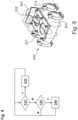
- the bleed passage 13 is connected by lines Z13 to the switching means 200, which is shown in figure 5 shown in perspective view.
- the switching means 200 in the exemplary embodiment has two butterfly valves 201, 202 rigidly coupled to one another, with the closing of the butterfly valve 201 reducing an air flow through the lines Z11 or the first outlet passage 11, and a closing of the butterfly valve 202 in the opposite direction thereto alternatively reducing an air flow through the lines Z13 or tap passage 13.
- a control means in the form of a correspondingly programmed controller 203 for actuating the butterfly valves 201, 202 of the switching means 200, which in one embodiment also controls the switching means 210, is described below with reference to 4 explained method for operating the gas turbine.
- step S10 the controller 203 checks whether cooling of the working channel wall 1 should be increased for the temporary reduction of a radial gap between the working channel wall 1 and one of the cages B and the butterfly valve 202 is not yet fully closed. If both are the case (S10: "Y"), it closes the butterfly valve 202 further in a step S20 and returns to step S10.
- the controller 203 checks in a step S30 whether cooling of the working channel wall 1 should be reduced for the temporary enlargement of a radial gap between the working channel wall 1 and one of the moving grids B and the butterfly valve 201 is not yet fully closed. If both are the case (S30: “Y”), it closes the butterfly valve 201 further in a step S40 and returns to step S10.
- the radial gap between the working channel wall 1 and the moving cage B can be temporarily reduced during operation.
- the described variation of the cooling can also reduce the structurally provided or maintained radial gap between the working channel wall 1 and the rotor grid B, since the probability of rubbing during operation can be reduced by the variation of the cooling.
Landscapes
- Engineering & Computer Science (AREA)
- Mechanical Engineering (AREA)
- General Engineering & Computer Science (AREA)
- Chemical & Material Sciences (AREA)
- Combustion & Propulsion (AREA)
- Structures Of Non-Positive Displacement Pumps (AREA)
Description
- Die vorliegende Erfindung betrifft ein Gehäuse für einen Verdichter einer Gasturbine, einen Verdichter und eine Gasturbine mit dem Gehäuse sowie ein Verfahren zum Betreiben der Gasturbine.
- Gasturbinenverdichter weisen ein Gehäuse mit einem Arbeitskanal auf, in dem mehrere Laufgitter bzw. beschaufelte Rotoren axial hintereinander angeordnet sind, um Luft im Arbeitskanal zu verdichten und diese einer Brennkammer zuzuführen. Zwischen Laufgitter und einer radial äußeren Arbeitskanalwandung ist ein Radialspalt ausgebildet, der sich im Betrieb thermisch bedingt verändern kann. Eine Vergrößerung des Radialspalts, insbesondere eine thermisch bedingte Vergrößerung im Betrieb und/oder ein konstruktiv größer vorgehaltener bzw. dimensionierter Radialspalt zur Vermeidung eines Anstreifens in verschiedenen Betriebsbedingungen, verschlechtert den Wirkungsgrad des Verdichters bzw. der Gasturbine.
- Die
US 2011/135456 A1 betrifft eine Gasturbinenanlage, die eine aktive Spaltregelung ermöglicht, um den beim Anfahren erforderlichen Spalt der Turbinenlaufschaufeln der ersten Stufe zu gewährleisten und den minimalen Spalt im Lastbetrieb zu erreichen. In dieser Gasturbinenanlage mit einem Kühler in einem Luftsystem zum Kühlen von Turbinenleitschaufeln der zweiten Stufe werden ein segmentierter Ring der ersten Stufe und ein segmentierter Ring der zweiten Stufe, die den Spitzen der Turbinenleitschaufeln der ersten und zweiten Stufe gegenüberliegen, von demselben Schaufelkranzelement getragen, und eine Kühlluft für die Turbinenstatorschaufeln der zweiten Stufe bildet einen Kühlluftstrom, der den Schaufelkranz kühlt, um die Wärmeausdehnung des Schaufelkranzes und den Spalt bezüglich der Spitzen zu kontrollieren. Die PatentschriftJP 2009 191655 - Eine Aufgabe einer Ausführung der vorliegenden Erfindung ist es, eine Gasturbine und/oder deren Betrieb zu verbessern.
- Diese Aufgabe wird durch ein Gehäuse für einen Verdichter einer Gasturbine mit den Merkmalen des Anspruchs 1 bzw. ein Verfahren mit den Merkmalen des Anspruchs 9 gelöst. Ansprüche 7, 8 stellen einen Verdichter bzw. eine Gasturbine mit einem hier beschriebenen Gehäuse unter Schutz. Vorteilhafte Ausführungsformen der Erfindung sind Gegenstand der Unteransprüche.
- Nach einer Ausführung der vorliegenden Erfindung weist ein Gehäuse für einen Verdichter, insbesondere ein Gehäuse eines Verdichters, für eine Gasturbine, insbesondere einer Gasturbine, insbesondere für ein Flugtriebwerk, insbesondere eines Flugtriebwerks, einen Arbeitskanal auf, in dem mehrere Laufgitter bzw. beschaufelte Rotoren mit Laufschaufeln (bezogen auf eine (Haupt)Maschinen- bzw. Rotationsachse des Verdichters) axial hintereinander angeordnet sind bzw. das hierzu bzw. zur Aufnahme dieser Laufgitter vorgesehen, insbesondere eingerichtet ist.
- In einer Ausführung ist das Gehäuse mehrteilig ausgebildet, insbesondere axial segmentiert, in einer Ausführung weist es miteinander verschraubte axiale Segmente auf. Hierdurch kann in einer Ausführung seine Herstellung und/oder Montage verbessert werden.
- Zusätzlich oder alternativ ist der Verdichter in einer Ausführung ein Mittel- oder Hochdruckverdichter, der stromabwärts hinter bzw. nach einem weiteren Verdichter angeordnet ist. Bei solchen Verdichtern kann die vorliegende Erfindung aufgrund der dort herrschenden Druck- und Temperaturverhältnisse mit besonderem Vorteil verwendet werden.
- Nach einer Ausführung der vorliegenden Erfindung weist eine, insbesondere radial äußere, Wandung des Arbeitskanals eine erste Luftentnahme auf, wobei das Gehäuse eine, insbesondere wenigstens abschnittsweise ein- oder mehrkanalige und/oder integral mit dem bzw. durch das Gehäuse selber ausgebildete, Kühlpassage aufweist, die wenigstens temporär, insbesondere wahlweise bzw. schaltbar und/oder in Abhängigkeit von einem (Radial)Spalt zwischen der Arbeitskanalwandung und wenigstens einem der Laufgitter, Luft von der ersten Luftentnahme zu einer ersten Austrittspassage zur Versorgung eines ersten oder mehrerer erster Entnahmeluftverbraucher(s) führt und dadurch die Arbeitskanalwandung kühlt bzw. hierzu eingerichtet ist bzw. verwendet wird, wobei diese erste Austrittspassage stromabwärts (von bzw. nach bzw. hinter) der ersten Luftentnahme angeordnet ist. In einer Ausführung ist die Kühlpassage bei, insbesondere an, der Arbeitskanalwandung angeordnet, insbesondere dieser benachbart, in einer Ausführung wenigstens teilweise durch diese begrenzt bzw. definiert, insbesondere durch eine Oberfläche der Arbeitskanalwandung, die einer den Arbeitskanal begrenzenden bzw. definierenden Oberfläche der Arbeitskanalwandung gegenüberliegt.
- Hierdurch kann in einer Ausführung die zur Versorgung eines bzw. mehrerer Entnahmeluftverbraucher entnommene Luft vorteilhaft zur wenigstens abschnittsweisen und/oder temporären Kühlung der Arbeitskanalwandung genutzt und so in einer Ausführung ein Radialspalt zwischen Arbeitskanalwandung und Laufgitter(n), insbesondere konstruktiv bzw. im Auslegungszustand und/oder temporär im Betrieb, reduziert und dadurch vorteilhaft ein Wirkungsgrad gesteigert werden.
- Eine Radialrichtung im Sinne der vorliegenden Erfindung erstreckt sich in einer Ausführung in fachüblicher Weise senkrecht auf der (Haupt)Maschinen- bzw. Rotationsachse und der Umfangs- bzw. Rotationsrichtung des Verdichters, so dass "radial außen" insbesondere einen größeren (radialen) Abstand zur (Haupt)Maschinen- bzw. Rotationsachse bezeichnet.
- In einer Ausführung grenzt die Kühlpassage wenigstens abschnittsweise an die Arbeitskanalwandung an bzw. ist dieser (radial) benachbart. Zusätzlich oder alternativ sind in einer Ausführung zwischen der ersten Luftentnahme und der ersten Austrittspassage wenigstens ein, insbesondere wenigstens drei, Laufgitter angeordnet bzw. das Gehäuse hierzu eingerichtet.
- Hierdurch kann in einer Ausführung (jeweils, insbesondere in Kombination) die Kühlung der Arbeitskanalwandung verbessert werden.
- Nach einer Ausführung der vorliegenden Erfindung weist die Arbeitskanalwandung eine zweite Luftentnahme, die stromabwärts (von bzw. nach) der ersten Luftentnahme angeordnet ist, und das Gehäuse eine Abführpassage von dieser zweiten Luftentnahme zu einer zweiten Austrittspassage zur Versorgung eines oder mehrerer Entnahmeluftverbraucher(s), insbesondere des bzw. eines oder mehrerer der ersten Entnahmeluftverbraucher(s) und/oder eines oder mehrerer hiervon verschiedener weiterer Entnahmeluftverbraucher(s), auf. Der bzw. einer oder mehrere der erste(n) und/oder weitere(n) Entnahmeluftverbraucher ist/sind in einer Ausführung (jeweils) ein gasturbinenferner bzw. von der Gasturbine beabstandeter Verbraucher und/oder können eine Abblasung, eine Enteisung, eine Lagersperr- und/oder eine Kabinen- bzw. Zellenbelüftung, oder dergleichen umfassen, insbesondere sein.
- Zusätzlich oder alternativ sind in einer Ausführung zwischen der ersten Luftentnahme und der zweiten Luftentnahme wenigstens ein, insbesondere wenigstens zwei, Laufgitter angeordnet bzw. das Gehäuse hierzu eingerichtet.
- Hierdurch können in einer Ausführung dieselben oder verschiedene Entnahmeluftverbraucher mit Luft unterschiedlicher Temperaturen und/oder Drücke versorgt werden.
- In einer Ausführung ist die zweite Austrittspassage stromaufwärts (von bzw. vor) der ersten Austrittspassage angeordnet, wobei das Gehäuse eine, insbesondere strömungstechnisch trennende bzw. getrennte, insbesondere wenigstens abschnittsweise ein- oder mehrkanalige, (Hin)Durchführung der Kühlpassage durch die Abführpassage aufweist, in einer Ausführung Durchgangskanäle der Kühlpassage durch die Abführpassage bzw. Durchgangskanäle der Abführpassage durch die Kühlpassage geführt sind bzw. diese durchgreifen.
- Hierdurch kann in einer Ausführung auch ein Abschnitt der Arbeitskanalwandung stromabwärts (von bzw. nach) der zweiten Luftentnahme durch Luft aus der ersten Luftentnahme bzw. die Kühlpassage gekühlt werden.
- In einer Ausführung weist diese Durchführung ein Gehäusebauteil mit axial beidseitig offenen ersten Durchgangskanälen und hiervon (strömungstechnisch) getrennten bzw. hiergegen dichten, radial beidseitig offenen zweiten Durchgangskanälen auf, wobei in einer Weiterbildung die ersten Durchgangskanäle die erste Luftentnahme und erste Austrittspassage und die zweiten Durchgangskanäle die zweite Luftentnahme und zweite Austrittspassage miteinander verbinden, in einer anderen Weiterbildung umgekehrt die zweiten Durchgangskanäle die erste Luftentnahme und erste Austrittspassage und die ersten Durchgangskanäle die zweite Luftentnahme und zweite Austrittspassage miteinander verbinden. In einer Ausführung ist das Gehäusebauteil einteilig und/oder mit wenigstens einem, insbesondere axial, benachbarten weiteren Gehäusebauteil, insbesondere axial, verschraubt und/oder die ersten und zweiten Durchgangskanäle integral miteinander ausgebildet. Insbesondere können die Außenwände der ersten Durchgangskanäle Innenwände der zweiten Durchgangskanäle bilden und umgekehrt.
- Hierdurch kann in einer Ausführung die Durchführung verbessert, insbesondere ihr strömungs- und/oder wärmetechnischer Wirkungsgrad erhöht und/oder ihre Herstellung und/oder Montage vereinfacht und/oder ihr Bauraum reduziert werden.
- In einer Ausführung bildet das Gehäusebauteil einen Abschnitt der Arbeitskanalwandung. Hierdurch kann in einer Ausführung die Durchführung (weiter) verbessert und/oder Herstellung, Montage und/oder Bauraum des Gehäuses verbessert werden.
- In einer Ausführung weist das Gehäuse eine Rückführpassage für Luft, insbesondere Leckageluft, von einem Bereich stromabwärts (von bzw. nach) der zweiten Luftentnahme, insbesondere stromabwärts (von bzw. nach) einem stromabwärtigsten Laufgitter des Verdichters, zu der Abführpassage auf, wobei das Gehäuse eine Durchführung der Rückführpassage durch die Kühlpassage aufweist. In einer Ausführung weist diese Durchführung axial beidseitig offene erste Durchgangskanäle und hiervon (strömungstechnisch) getrennte bzw. hiergegen dichte, radial beidseitig offene zweite Durchgangskanäle auf, wobei in einer Weiterbildung die Rückführpassage die ersten Durchgangskanäle aufweist und die zweiten Durchgangskanäle die erste Luftentnahme und Austrittspassage miteinander verbinden, in einer anderen Weiterbildung umgekehrt die Rückführpassage die zweiten Durchgangskanäle aufweist und die ersten Durchgangskanäle die erste Luftentnahme und Austrittspassage miteinander verbinden.
- Hierdurch kann in einer Ausführung vorteilhaft auch Luft von stromabwärts der zweiten Luftentnahme zur Versorgung des bzw. der Entnahmeluftverbraucher(s) genutzt werden, der/die durch die (Luft aus der) zweiten Luftentnahme versorgbar ist/sind bzw. versorgt wird/werden.
- In einer Ausführung weist das Gehäuse eine (zusätzliche) Abzapfpassage zur Versorgung des bzw. eines oder mehrerer der ersten Entnahmeluftverbraucher(s) mit Luft von der ersten Luftentnahme auf, wobei die Abzapfpassage, insbesondere axial, von der ersten Austrittspassage beabstandet, in einer Ausführung stromaufwärts (von bzw. vor) der ersten Austrittspassage und/oder der zweiten Austrittspassage angeordnet ist.
- Hierdurch kann in einer Ausführung auch kältere Luft aus der ersten Luftentnahme zur Versorgung des ersten Entnahmeluftverbrauchers genutzt werden, die die Kühlpassage nicht oder wenigstens nicht vollständig bzw. bis zur ersten Austrittspassage durchströmt hat.
- In einer Ausführung weist das Gehäuse bzw. der Verdichter ein ein- oder mehrteiliges Schaltmittel auf, durch das bzw. mit dem ein Luftstrom durch die erste Austrittspassage und/oder ein Luftstrom durch die zweite Austrittspassage und/oder ein Luftstrom durch die Abzapfpassage wahlweise reduziert, insbesondere gesperrt, wird bzw. werden kann, insbesondere in Abhängigkeit, insbesondere zur wenigstens temporären Reduzierung, von einem Spalt zwischen der Arbeitskanalwandung und wenigstens einem der Laufgitter, bzw. das hierzu eingerichtet ist bzw. verwendet wird, insbesondere zum alternativen bzw. komplementären Reduzieren, insbesondere Sperren, eines Luftstrom entweder durch die erste Austrittspassage oder die Abzapfpassage.
- In einer Ausführung kann das Schaltmittel ein oder mehrere Ventile, insbesondere Stell-, insbesondere Sperrventile, und/oder ein Steuermittel zum (An)Steuern, insbesondere Regeln, dieser Ventile aufweisen. In einer Ausführung sind ein oder mehrere Ventile zum Reduzieren, insbesondere Sperren, eines Luftstroms durch die erste Austrittspassage und ein oder mehrere Ventile zum Reduzieren, insbesondere Sperren, eines Luftstrom durch die Abzapfpassage und/oder ein oder mehrere Ventile zum Reduzieren, insbesondere Sperren, eines Luftstrom durch die zweite Austrittspassage in einem gemeinsamen Gehäuse angeordnet. Zusätzlich oder alternativ ist in einer Ausführung wenigstens ein Ventil, insbesondere Ventilglied, zum Reduzieren, insbesondere Sperren, eines Luftstrom durch die erste Austrittspassage und wenigstens ein Ventil, insbesondere Ventilglied, zum Reduzieren, insbesondere Sperren, eines Luftstrom durch die Abzapfpassage gegensinnig miteinander gekoppelt bzw. verstellbar.
- Hierdurch kann in einer Ausführung Luft aus der ersten Luftentnahme wahlweise durch die erste Austrittspassage und/oder die Abzapfpassage zu dem bzw. den ersten Entnahmeluftverbraucher(n) geleitet und so insbesondere die Versorgung des/der ersten Entnahmeluftverbraucher(s) und/oder die Kühlung der Arbeitskanalwandung bzw. der Spalt unterschiedlichen Betriebsbedingungen angepasst werden. In einer Ausführung wird zur Erhöhung der Kühlung mehr Luft aus der ersten Luftentnahme durch die Kühlpassage und die erste Austrittspassage geleitet, zur Reduzierung der Kühlung weniger Luft durch die Kühlpassage und die erste Austrittspassage, insbesondere stattdessen mehr Luft aus der ersten Luftentnahme durch die Abzapfpassage, bzw. das Schaltmittel entsprechend verstellt.
- In einer Ausführung weist die Kühlpassage einen oder mehrere miteinander kommunizierende, in einer Ausführung axial voneinander beabstandete, Ringräume auf. Zusätzlich oder alternativ weist in einer Ausführung die Abführpassage einen oder mehrere miteinander kommunizierende, in einer Ausführung radial voneinander beabstandete, Ringräume auf. Zusätzlich oder alternativ weist in einer Ausführung die Rückführpassage einen oder mehrere miteinander kommunizierende Ringräume auf.
- Zusätzlich oder alternativ ist in einer Ausführung die erste Luftentnahme und/oder Austrittspassage (jeweils) mit einem, insbesondere gegenüber ihr vergrößerten, Ringraum verbunden, insbesondere an diesen angrenzend. Zusätzlich oder alternativ ist in einer Ausführung die zweite Luftentnahme und/oder Austrittspassage (jeweils) mit einem, insbesondere gegenüber ihr vergrößerten, Ringraum verbunden, insbesondere an diesen angrenzend. Zusätzlich oder alternativ ist in einer Ausführung die Abzapfpassage mit einem, insbesondere gegenüber ihr vergrößerten, Ringraum verbunden, insbesondere an diesen angrenzend.
- Durch solche Ringräume können in einer Ausführung die Kühlung der Arbeitskanalwandung und/oder die Luftströmung verbessert, insbesondere homogenisiert und/oder Verluste reduziert werden.
- Zusätzlich oder alternativ kann in einer Ausführung die erste Luftentnahme und/oder die erste Austrittspassage und/oder die zweite Luftentnahme und/oder die zweite Austrittspassage und/oder die Abzapfpassage (jeweils) mehrere in Umfangsrichtung verteilte Öffnungen oder einen (in Umfangsrichtung) umlaufenden Spalt aufweisen, insbesondere hieraus bestehen. Zusätzlich oder alternativ ist in einer Ausführung die erste Luftentnahme und/oder die zweite Luftentnahme (jeweils) zwischen einem Laufgitter und einem (axial) benachbarten, insbesondere stromaufwärtigen oder - abwärtigen, Leitgitter mit mehreren in Umfangsrichtung verteilten gehäuseseitigen, insbesondere -festen, Leitschaufeln angeordnet.
- Durch eine Anordnung einer Luftentnahme zwischen Lauf- und Leitgitter kann in einer Ausführung die Entnahme der Luft und/oder die Strömung im Arbeitskanal verbessert werden. Durch eine Luftentnahme mit verteilten Öffnungen kann in einer Ausführung die Strömung im Arbeitskanal verbessert werden, durch eine Luftentnahme mit einem umlaufenden Spalt die Entnahme der Luft. Durch eine Austritts- bzw. Abzapfpassage mit verteilten Öffnungen kann in einer Ausführung eine Weiterleitung zu dem entsprechenden Entnahmeluftverbraucher bzw. Schaltmittel verbessert werden.
- Ein Mittel im Sinne der vorliegenden Erfindung kann hard- und/oder softwaretechnisch ausgebildet sein, insbesondere eine, vorzugsweise mit einem Speicher- und/oder Bussystem daten- bzw. signalverbundene, insbesondere digitale, Verarbeitungs-, insbesondere Mikroprozessoreinheit (CPU) und/oder ein oder mehrere Programme oder Programmmodule aufweisen. Die CPU kann dazu ausgebildet sein, Befehle, die als ein in einem Speichersystem abgelegtes Programm implementiert sind, abzuarbeiten, Eingangssignale von einem Datenbus zu erfassen und/oder Ausgangssignale an einen Datenbus abzugeben. Ein Speichersystem kann ein oder mehrere, insbesondere verschiedene, Speichermedien, insbesondere optische, magnetische, Festkörper- und/oder andere nicht-flüchtige Medien aufweisen. Das Programm kann derart beschaffen sein, dass es die hier beschriebenen Verfahren verkörpert bzw. auszuführen imstande ist, sodass die CPU die Schritte solcher Verfahren ausführen kann und damit insbesondere einen Luftstrom durch die erste und/oder zweite Austrittspassage und/oder durch die Abzapfpassage, insbesondere in Abhängigkeit von einem Spalt zwischen der Arbeitskanalwandung und wenigstens einem der Laufgitter, reduzieren, insbesondere sperren, kann. Ein Computerprogrammprodukt kann in einer Ausführung ein, insbesondere nicht-flüchtiges, Speichermedium zum Speichern eines Programms bzw. mit einem darauf gespeicherten Programm aufweisen, insbesondere sein, wobei ein Ausführen dieses Programms ein System bzw. eine Steuerung, insbesondere einen Computer, dazu veranlasst, ein hier beschriebenes Verfahren bzw. einen oder mehrere seiner Schritte auszuführen.
- In einer Ausführung werden ein oder mehrere, insbesondere alle, Schritte des Verfahrens vollständig oder teilweise automatisiert durchgeführt, insbesondere durch das bzw. die Mittel.
- Weitere vorteilhafte Weiterbildungen der vorliegenden Erfindung ergeben sich aus den Unteransprüchen und der nachfolgenden Beschreibung bevorzugter Ausführungen. Hierzu zeigt, teilweise schematisiert:
- Fig. 1
- einen Verdichter einer Gasturbine mit einem Gehäuse nach einer Ausführung der vorliegenden Erfindung in einem Meridianhalbschnitt;
- Fig. 2
- ein Gehäusebauteil des Gehäuses in einer perspektivischen Ansicht;
- Fig. 3
- einen Teil des Gehäuses in einer perspektivischen Ansicht;
- Fig. 4
- ein Verfahren zum Betreiben der Gasturbine nach einer Ausführung der vorliegenden Erfindung; und
- Fig. 5
- ein Schaltmittel in einer perspektivischen Ansicht.
-
Fig. 1 zeigt einen Verdichter einer Gasturbine mit einem Gehäuse nach einer Ausführung der vorliegenden Erfindung in einem Meridianhalbschnitt längs einer (Haupt)Maschinen- bzw. Rotationsachse (horizontal inFig. 1 ). - Das mehrteilige, axial segmentierte Gehäuse weist einen Arbeitskanal A auf, in dem mehrere Laufgitter bzw. -schaufeln B axial hintereinander angeordnet sind, zwischen denen gehäuseseitige Leitgitter bzw. -schaufeln V angeordnet sind.
- Eine radial äußere (oben in
Fig. 1 ) Arbeitskanalwandung 1 weist eine erste Luftentnahme mit einem umlaufenden Spalt 10 und eine zweite Luftentnahme mit einem umlaufenden Spalt 20 stromabwärts (rechts inFig. 1 ) hinter der ersten Luftentnahme auf. - Das Gehäuse weist eine erste Austrittspassage mit mehreren in Umfangsrichtung verteilte Öffnungen 11 zur Versorgung eines ersten oder mehrerer erster Entnahmeluftverbraucher(s) 100 auf, die durch Leitungen Z11 mit einem Schaltmittel 200 verbunden ist bzw. sind, welches seinerseits durch Leitungen V1 mit dem bzw. den ersten Entnahmeluftverbraucher(n) 100 verbunden ist.
- Das Gehäuse weist weiter eine zweite Austrittspassage 21 zur Versorgung wenigstens eines weiteren Entnahmeluftverbrauchers 110 und/oder des bzw. wenigstens eines der ersten Entnahmeluftverbraucher(s) 100 auf, die durch eine oder mehrere Leitungen Z21 mit einem Schaltmittel 210 verbunden ist, welches seinerseits durch eine bzw. mehrere Leitungen V2 mit dem bzw. den weiteren Entnahmeluftverbraucher(n) 110 bzw. dem bzw. den ersten Entnahmeluftverbraucher(n) 100 verbunden ist.
- Die erste Austrittspassage 11 ist stromabwärts nach bzw. hinter der ersten und zweiten Luftentnahme 10, 20 sowie stromabwärts nach der zweiten Austrittspassage 21 angeordnet.
- Eine Kühlpassage 12 zur Führung von Luft von der ersten Luftentnahme 10 zur ersten Austrittspassage 11 ist an der Arbeitskanalwandung 1 angeordnet, um diese zu kühlen. Sie weist mehrere miteinander kommunizierende Ringräume auf.
- Zwischen der zweiten Luftentnahme 20 und der zweiten Austrittspassage 21 weist das Gehäuse eine Abführpassage 22 zur Führung von Luft (doppellinig in
Fig. 1 ) von der zweiten Luftentnahme 20 zur zweiten Austrittspassage 21 auf, die ebenfalls miteinander kommunizierende Ringräume aufweist. - Das Gehäuse weist ein einteiliges Gehäusebauteil 30, welches in
Fig. 2 in einer perspektivischen Ansicht gezeigt und axial mit angrenzenden Gehäusebauteilen verschraubt ist, mit axial beidseitig offenen ersten Durchgangskanälen 31, die Ringräume der Kühlpassage 12 verbinden, und hiermit integral ausgebildeten, aber von diesen strömungstechnisch getrennten, radial beidseitig offenen zweiten Durchgangskanälen 23 auf, die einen an die zweite Luftentnahme 20 angrenzenden Ringraum und einen an die zweite Austrittspassage 21 angrenzenden Ringraum der Abführpassage 22 (unten bzw. oben inFig. 1 ) verbinden. Mithin bilden Außenwände der ersten Durchgangskanäle Innenwände der zweiten Durchgangskanäle. Zugleich begrenzt bzw. definiert das Gehäusebauteil 30 die zweite Luftentnahme 20 bzw. deren umlaufenden Spalt stromaufwärts und bildet somit den entsprechenden Abschnitt der Arbeitskanalwandung A. - Das Gehäuse weist weiter eine Rückführpassage 40 zur Rückführung von Leckageluft (doppellinig gestrichelt in
Fig. 1 ) zu der Abführpassage 22 auf, die stromabwärts hinter dem stromabwärtigsten Laufgitter ausströmt, wobei das Gehäuse eine Durchführung der Rückführpassage im Form mehrerer Verbindungsrohe 33 durch die Kühlpassage 12 aufweist, die einen an die erste Austrittspassage 11 angrenzenden Ringraum der Kühlpassage 12 durchgreifen. - Das Gehäuse weist weiter eine Abzapfpassage mit mehreren in Umfangsrichtung verteilten Öffnungen 13 zur Versorgung des bzw. der ersten Entnahmeluftverbraucher(s) 100 mit Luft von der ersten Luftentnahme 10 auf, wobei die Abzapfpassage 13 stromaufwärts vor der ersten und zweiten Austrittspassage 11, 21 angeordnet ist.
- Die Abzapfpassage 13 ist durch Leitungen Z13 mit dem Schaltmittel 200 verbunden, welches in
Fig. 5 in perspektivischer Ansicht gezeigt ist. - Wie in
Fig. 5 erkennbar, weist das Schaltmittel 200 im Ausführungsbeispiel zwei miteinander starr gekoppelte Schmetterlingsventile 201, 202 auf, wobei das Schließen des Schmetterlingsventils 201 einen Luftstrom durch die Leitungen Z11 bzw. erste Austrittspassage 11 reduziert, ein hierzu gegensinniges Schließen des Schmetterlingsventils 202 alternativ einen Luftstrom durch die Leitungen Z13 bzw. Abzapfpassage 13. - Ein Steuermittel in Form einer entsprechend programmierten Steuerung 203 zum Aktuieren der Schmetterlingsventile 201, 202 des Schaltmittels 200, die in einer Ausführung auch das Schaltmittel 210 steuert, führt ein nachfolgend mit Bezug auf
Fig. 4 erläutertes Verfahren zum Betreiben der Gasturbine durch. - In einem Schritt S10 prüft die Steuerung 203, ob zur temporäreren Reduzierung eines Radialspalts zwischen der Arbeitskanalwandung 1 und einem der Laufgitter B eine Kühlung der Arbeitskanalwandung 1 erhöht werden soll und das Schmetterlingsventil 202 noch nicht vollständig geschlossen ist. Ist beides der Fall (S10: "Y"), schließt sie in einem Schritt S20 das Schmetterlingsventil 202 weiter und kehrt zu Schritt S10 zurück.
- Andernfalls (S10: "N") prüft die Steuerung 203 in einem Schritt S30, ob zur temporäreren Vergrößerung eines Radialspalts zwischen der Arbeitskanalwandung 1 und einem der Laufgitter B eine Kühlung der Arbeitskanalwandung 1 reduziert werden soll und das Schmetterlingsventil 201 noch nicht vollständig geschlossen ist. Ist beides der Fall (S30: "Y"), schließt sie in einem Schritt S40 das Schmetterlingsventil 201 weiter und kehrt zu Schritt S10 zurück.
- Andernfalls (S30: "N"), d. h. wenn die Kühlung der Arbeitskanalwandung 1 weder erhöht noch reduziert werden soll oder dies nicht möglich ist, da das entsprechende Schmetterlingsventil bereits vollständig geschlossen ist, kehrt die Steuerung 203 bzw. das Verfahren zu Schritt S10 zurück, ohne die Schmetterlingsventile 201, 202 zu verstellen.
- Man erkennt, dass einerseits durch temporäres Schließen des Schmetterlingsventils 202 bzw. der Abzapfpassage 13 und entsprechend( erhöht)e Kühlung der Arbeitskanalwandung 1 der Radialspalt zwischen Arbeitskanalwandung 1 und Laufgitter B im Betrieb temporär reduziert werden kann. Zusätzlich kann durch die beschriebene Variation der Kühlung auch der konstruktiv vorgesehene bzw. -haltene Radialspalt zwischen Arbeitskanalwandung 1 und Laufgitter B reduziert werden, da die Wahrscheinlichkeit eines Anstreifens im Betrieb durch die Variation der Kühlung reduziert werden kann.
- Obwohl in der vorhergehenden Beschreibung exemplarische Ausführungen erläutert wurden, sei darauf hingewiesen, dass eine Vielzahl von Abwandlungen möglich ist. Außerdem sei daraufhingewiesen, dass es sich bei den exemplarischen Ausführungen lediglich um Beispiele handelt, die den Schutzbereich, die Anwendungen und den Aufbau in keiner Weise einschränken sollen. Vielmehr wird dem Fachmann durch die vorausgehende Beschreibung ein Leitfaden für die Umsetzung von mindestens einer exemplarischen Ausführung gegeben, wobei diverse Änderungen, insbesondere in Hinblick auf die Funktion und Anordnung der beschriebenen Bestandteile, vorgenommen werden können, ohne den Schutzbereich zu verlassen, wie er sich aus den Ansprüchen und diesen äquivalenten Merkmalskombinationen ergibt.
-
- 1
- Arbeitskanalwandung
- 10
- erste Luftentnahme
- 11
- erste Austrittspassage
- 12
- Kühlpassage
- 13
- Abzapfpassage
- 20
- zweite Luftentnahme
- 21
- zweite Austrittspassage
- 22
- Abführpassage
- 23
- zweite Durchgangskanäle
- 30
- Gehäusebauteil (Durchführung)
- 31
- erste Durchgangskanälen
- 33
- Verbindungsrohre (Durchführung)
- 40
- Rückführpassage
- 100
- erster Entnahmeluftverbraucher
- 110
- weiterer Entnahmeluftverbraucher
- 200,210
- Schaltmittel
- 201, 202
- Schmetterlingsventil
- 203
- Steuerung
- Z11, Z13, Z21, V1, V2
- Leitung
- A
- Arbeitskanal
- B
- Laufgitter
- V
- Leitgitter
Claims (10)
- Gehäuse für einen Verdichter einer Gasturbine, mit einem Arbeitskanal (A) zur Aufnahme mehrerer axial hintereinander angeordneter Laufgitter (B), wobei eine Wandung (1) des Arbeitskanals eine erste Luftentnahme (10) aufweist, wobei das Gehäuse eine Kühlpassage (12) zur Kühlung dieser Arbeitskanalwandung (1) durch Führung von Luft von der ersten Luftentnahme (10) zu einer ersten Austrittspassage (11) zur Versorgung wenigstens eines ersten Entnahmeluftverbrauchers (100) aufweist, wobei die erste Austrittspassage (11) stromabwärts der ersten Luftentnahme (10) angeordnet ist, und wobei die Arbeitskanalwandung (1) eine zweite Luftentnahme (20) stromabwärts der ersten Luftentnahme (10) und das Gehäuse eine Abführpassage (22) von dieser zweiten Luftentnahme (20) zu einer zweiten Austrittspassage (21) zur Versorgung wenigstens eines Entnahmeluftverbrauchers (100, 110) aufweist dadurch gekennzeichnet, dass die zweite Austrittspassage (21) stromaufwärts der ersten Austrittspassage (11) angeordnet ist und das Gehäuse eine Durchführung (23, 30, 31) der Kühlpassage (12) durch die Abführpassage (22) aufweist.
- Gehäuse nach dem vorhergehenden Anspruch, dadurch gekennzeichnet, dass diese Durchführung ein Gehäusebauteil (30) mit axial beidseitig offenen ersten Durchgangskanälen (31) und hiervon getrennten radial beidseitig offenen zweiten Durchgangskanälen (23) aufweist.
- Gehäuse nach dem vorhergehenden Anspruch, dadurch gekennzeichnet, dass das Gehäusebauteil (30) einen Abschnitt der Arbeitskanalwandung (1) bildet.
- Gehäuse nach einem der vorhergehenden Ansprüche, gekennzeichnet durch eine Rückführpassage (40) für Luft von einem Bereich stromabwärts der zweiten Luftentnahme (20) zu der Abführpassage (22), wobei das Gehäuse eine Durchführung (33) der Rückführpassage (40) durch die Kühlpassage (12) aufweist.
- Gehäuse nach einem der vorhergehenden Ansprüche, gekennzeichnet durch eine von der ersten Austrittspassage (11) beabstandete Abzapfpassage (13) zur Versorgung des ersten Entnahmeluftverbrauchers (100) mit Luft von der ersten Luftentnahme (10), welche insbesondere stromaufwärts der ersten Austrittspassage (11) angeordnet ist.
- Gehäuse nach einem der vorhergehenden Ansprüche, gekennzeichnet durch ein Schaltmittel (200-210) zum wahlweisen, insbesondere alternativen, Reduzieren eines Luftstroms durch die erste und/oder zweite Austrittspassage (11, 21) und/oder durch die Abzapfpassage (13), insbesondere in Abhängigkeit von einem Spalt zwischen der Arbeitskanalwandung (1) und wenigstens einem der Laufgitter (B).
- Verdichter für eine Gasturbine, der ein Gehäuse nach einem der vorhergehenden Ansprüche aufweist, in dessen Arbeitskanal (A) mehrere Laufgitter (B) axial hintereinander angeordnet sind.
- Gasturbine, insbesondere für ein Flugtriebwerk, mit einem Verdichter nach dem vorhergehenden Anspruch.
- Verfahren zum Betreiben einer Gasturbine nach dem vorhergehenden Anspruch, wobei wenigstens temporär, insbesondere wahlweise, Luft zur Kühlung der Arbeitskanalwandung (1) von der ersten Luftentnahme (10) durch die Kühlpassage (12) zu der ersten Austrittspassage (11) geführt wird.
- Verfahren nach dem vorhergehenden Anspruch, wobei Luft in Abhängigkeit von einem Spalt zwischen der Arbeitskanalwandung (1) und wenigstens einem der Laufgitter (B) von der ersten Luftentnahme (10) durch die Kühlpassage (12) zu der ersten Austrittspassage (11) geführt wird.
Applications Claiming Priority (1)
| Application Number | Priority Date | Filing Date | Title |
|---|---|---|---|
| DE102017216119.1A DE102017216119A1 (de) | 2017-09-13 | 2017-09-13 | Gasturbinenverdichtergehäuse |
Publications (2)
| Publication Number | Publication Date |
|---|---|
| EP3456942A1 EP3456942A1 (de) | 2019-03-20 |
| EP3456942B1 true EP3456942B1 (de) | 2022-03-23 |
Family
ID=63311876
Family Applications (1)
| Application Number | Title | Priority Date | Filing Date |
|---|---|---|---|
| EP18189684.6A Not-in-force EP3456942B1 (de) | 2017-09-13 | 2018-08-20 | Gasturbinenverdichtergehäuse |
Country Status (3)
| Country | Link |
|---|---|
| US (1) | US10830084B2 (de) |
| EP (1) | EP3456942B1 (de) |
| DE (1) | DE102017216119A1 (de) |
Families Citing this family (1)
| Publication number | Priority date | Publication date | Assignee | Title |
|---|---|---|---|---|
| CN119687025A (zh) * | 2025-02-25 | 2025-03-25 | 中国航发四川燃气涡轮研究院 | 压气机径向间隙主动控制结构及控制方法 |
Citations (1)
| Publication number | Priority date | Publication date | Assignee | Title |
|---|---|---|---|---|
| JP2009191655A (ja) * | 2008-02-12 | 2009-08-27 | Mitsubishi Heavy Ind Ltd | 軸流圧縮機およびこれを用いたガスタービン |
Family Cites Families (22)
| Publication number | Priority date | Publication date | Assignee | Title |
|---|---|---|---|---|
| US2837270A (en) * | 1952-07-24 | 1958-06-03 | Gen Motors Corp | Axial flow compressor |
| US4329114A (en) * | 1979-07-25 | 1982-05-11 | The United States Of America As Represented By The Administrator Of The National Aeronautics And Space Administration | Active clearance control system for a turbomachine |
| US5160241A (en) * | 1991-09-09 | 1992-11-03 | General Electric Company | Multi-port air channeling assembly |
| US5351478A (en) * | 1992-05-29 | 1994-10-04 | General Electric Company | Compressor casing assembly |
| JPH0754669A (ja) * | 1993-08-09 | 1995-02-28 | Mitsubishi Heavy Ind Ltd | ガスタービン冷却空気制御装置 |
| US5611197A (en) * | 1995-10-23 | 1997-03-18 | General Electric Company | Closed-circuit air cooled turbine |
| US6968696B2 (en) * | 2003-09-04 | 2005-11-29 | Siemens Westinghouse Power Corporation | Part load blade tip clearance control |
| WO2010084573A1 (ja) | 2009-01-20 | 2010-07-29 | 三菱重工業株式会社 | ガスタービン設備 |
| DE102009021384A1 (de) * | 2009-05-14 | 2010-11-18 | Mtu Aero Engines Gmbh | Strömungsvorrichtung mit Kavitätenkühlung |
| EP2552780A1 (de) | 2010-03-31 | 2013-02-06 | United Technologies Corporation | Abstandskontrolle zwischen turbinenschaufelspitzen |
| US9458855B2 (en) * | 2010-12-30 | 2016-10-04 | Rolls-Royce North American Technologies Inc. | Compressor tip clearance control and gas turbine engine |
| US9260974B2 (en) | 2011-12-16 | 2016-02-16 | General Electric Company | System and method for active clearance control |
| US9341074B2 (en) | 2012-07-25 | 2016-05-17 | General Electric Company | Active clearance control manifold system |
| US9562475B2 (en) * | 2012-12-19 | 2017-02-07 | Siemens Aktiengesellschaft | Vane carrier temperature control system in a gas turbine engine |
| US9598974B2 (en) | 2013-02-25 | 2017-03-21 | Pratt & Whitney Canada Corp. | Active turbine or compressor tip clearance control |
| US10330012B2 (en) | 2014-02-04 | 2019-06-25 | United Technologies Corporation | Brackets for gas turbine engine components |
| WO2015153171A1 (en) | 2014-03-31 | 2015-10-08 | United Technologies Corporation | Active clearance control for gas turbine engine |
| DE102014217830A1 (de) | 2014-09-05 | 2016-03-10 | Rolls-Royce Deutschland Ltd & Co Kg | Luftleitvorrichtung und Turbomaschine mit Luftleitvorrichtung |
| US20160290214A1 (en) | 2015-04-02 | 2016-10-06 | General Electric Company | Heat pipe cooled turbine casing system for clearance management |
| EP3112607B1 (de) | 2015-07-02 | 2018-10-24 | Ansaldo Energia Switzerland AG | Betriebverfahren für gasturbinenabkühlphase |
| DE102015215479A1 (de) | 2015-08-13 | 2017-02-16 | Rolls-Royce Deutschland Ltd & Co Kg | System zur aktiven Einstellung einer radialen Spaltgröße und Flugzeugtriebwerk mit einem System zur aktiven Einstellung einer radialen Spaltgröße |
| US20170114667A1 (en) | 2015-10-23 | 2017-04-27 | General Electric Company | Active clearance control with integral double wall heat shielding |
-
2017
- 2017-09-13 DE DE102017216119.1A patent/DE102017216119A1/de not_active Withdrawn
-
2018
- 2018-08-20 EP EP18189684.6A patent/EP3456942B1/de not_active Not-in-force
- 2018-09-12 US US16/129,401 patent/US10830084B2/en not_active Expired - Fee Related
Patent Citations (1)
| Publication number | Priority date | Publication date | Assignee | Title |
|---|---|---|---|---|
| JP2009191655A (ja) * | 2008-02-12 | 2009-08-27 | Mitsubishi Heavy Ind Ltd | 軸流圧縮機およびこれを用いたガスタービン |
Also Published As
| Publication number | Publication date |
|---|---|
| US10830084B2 (en) | 2020-11-10 |
| DE102017216119A1 (de) | 2019-03-14 |
| EP3456942A1 (de) | 2019-03-20 |
| US20190101017A1 (en) | 2019-04-04 |
Similar Documents
| Publication | Publication Date | Title |
|---|---|---|
| DE602004000527T2 (de) | Verfahren zur Kühlung von heissen Turbinenbauteilen mittels eines teilweise in einem externen Wärmetauscher gekühlten Luftstromes und so gekühltes Turbinentriebwerk | |
| DE60031744T2 (de) | Turbinenbrennkammeranordnung | |
| EP0235641B1 (de) | Schaufel- und Dichtspaltoptimierungseinrichtung für Verdichter von Gasturbinentriebwerken | |
| DE112016005433B4 (de) | Gasturbine und bauteiltemperatur-einstellverfahren dafür | |
| EP2224099B1 (de) | Laufspalteinstellungssystem einer Fluggasturbine | |
| DE112015003934B4 (de) | Gasturbine | |
| DE3028137C2 (de) | ||
| CH700018B1 (de) | Verfahren zum Regeln der Temperatur in Turbinenlaufradzwischenräumen. | |
| DE102011052235A1 (de) | Druckbetätigter Stopfen | |
| EP3093447B1 (de) | Rotor einer turbine einer gasturbine mit verbesserter kühlluftführung | |
| EP3121372A1 (de) | Gekühltes turbinenlaufrad für ein flugtriebwerk | |
| WO2001065095A1 (de) | Kühlluftsystem | |
| DE69909585T2 (de) | Kühlluftsystem einer Gasturbine | |
| DE102011052236A1 (de) | Profilierter axial-radialer Auslassdiffusor | |
| DE112011104298T5 (de) | Gasturbinenmotor mit Sekundärluftstromkreis | |
| EP3121371B1 (de) | Turbine mit gekühlten turbinenleitschaufeln | |
| EP2450531B1 (de) | Axialverdichterkühlung | |
| CH708795A2 (de) | Segment für ein ringförmiges Rotationsmaschinen-Leitradbauteil. | |
| DE102015107844A1 (de) | Rotorblattkühlströmung | |
| DE102014106243A1 (de) | Turbinenlaufschaufel für einen Turbinenabschnitt einer Gasturbine | |
| DE102019002712B4 (de) | Gasturbinensystem | |
| DE102014110749A1 (de) | Systeme und Verfahren betreffend die axiale Positionierung von Turbinengehäusen und den Schaufelspitzenspalt in Gasturbinen | |
| DE102014102778B4 (de) | Strömungshülse zur thermischen Steuerung eines doppelwandigen Turbinengehäuses und Turbinengehäuse mit derartiger Strömungshülse | |
| DE102014103009A1 (de) | Gehäuse mit Kühleinheit für eine Gasturbine | |
| WO2016055354A1 (de) | Gasturbine mit zwei drallzuleitungen zur kühlung des rotors |
Legal Events
| Date | Code | Title | Description |
|---|---|---|---|
| PUAI | Public reference made under article 153(3) epc to a published international application that has entered the european phase |
Free format text: ORIGINAL CODE: 0009012 |
|
| STAA | Information on the status of an ep patent application or granted ep patent |
Free format text: STATUS: THE APPLICATION HAS BEEN PUBLISHED |
|
| AK | Designated contracting states |
Kind code of ref document: A1 Designated state(s): AL AT BE BG CH CY CZ DE DK EE ES FI FR GB GR HR HU IE IS IT LI LT LU LV MC MK MT NL NO PL PT RO RS SE SI SK SM TR |
|
| AX | Request for extension of the european patent |
Extension state: BA ME |
|
| STAA | Information on the status of an ep patent application or granted ep patent |
Free format text: STATUS: REQUEST FOR EXAMINATION WAS MADE |
|
| 17P | Request for examination filed |
Effective date: 20190918 |
|
| RBV | Designated contracting states (corrected) |
Designated state(s): AL AT BE BG CH CY CZ DE DK EE ES FI FR GB GR HR HU IE IS IT LI LT LU LV MC MK MT NL NO PL PT RO RS SE SI SK SM TR |
|
| STAA | Information on the status of an ep patent application or granted ep patent |
Free format text: STATUS: EXAMINATION IS IN PROGRESS |
|
| 17Q | First examination report despatched |
Effective date: 20201221 |
|
| GRAP | Despatch of communication of intention to grant a patent |
Free format text: ORIGINAL CODE: EPIDOSNIGR1 |
|
| STAA | Information on the status of an ep patent application or granted ep patent |
Free format text: STATUS: GRANT OF PATENT IS INTENDED |
|
| INTG | Intention to grant announced |
Effective date: 20211028 |
|
| GRAS | Grant fee paid |
Free format text: ORIGINAL CODE: EPIDOSNIGR3 |
|
| GRAA | (expected) grant |
Free format text: ORIGINAL CODE: 0009210 |
|
| STAA | Information on the status of an ep patent application or granted ep patent |
Free format text: STATUS: THE PATENT HAS BEEN GRANTED |
|
| AK | Designated contracting states |
Kind code of ref document: B1 Designated state(s): AL AT BE BG CH CY CZ DE DK EE ES FI FR GB GR HR HU IE IS IT LI LT LU LV MC MK MT NL NO PL PT RO RS SE SI SK SM TR |
|
| REG | Reference to a national code |
Ref country code: GB Ref legal event code: FG4D Free format text: NOT ENGLISH |
|
| REG | Reference to a national code |
Ref country code: CH Ref legal event code: EP |
|
| REG | Reference to a national code |
Ref country code: IE Ref legal event code: FG4D Free format text: LANGUAGE OF EP DOCUMENT: GERMAN |
|
| REG | Reference to a national code |
Ref country code: DE Ref legal event code: R096 Ref document number: 502018009155 Country of ref document: DE |
|
| REG | Reference to a national code |
Ref country code: AT Ref legal event code: REF Ref document number: 1477579 Country of ref document: AT Kind code of ref document: T Effective date: 20220415 |
|
| REG | Reference to a national code |
Ref country code: LT Ref legal event code: MG9D |
|
| REG | Reference to a national code |
Ref country code: NL Ref legal event code: MP Effective date: 20220323 |
|
| PG25 | Lapsed in a contracting state [announced via postgrant information from national office to epo] |
Ref country code: SE Free format text: LAPSE BECAUSE OF FAILURE TO SUBMIT A TRANSLATION OF THE DESCRIPTION OR TO PAY THE FEE WITHIN THE PRESCRIBED TIME-LIMIT Effective date: 20220323 Ref country code: RS Free format text: LAPSE BECAUSE OF FAILURE TO SUBMIT A TRANSLATION OF THE DESCRIPTION OR TO PAY THE FEE WITHIN THE PRESCRIBED TIME-LIMIT Effective date: 20220323 Ref country code: NO Free format text: LAPSE BECAUSE OF FAILURE TO SUBMIT A TRANSLATION OF THE DESCRIPTION OR TO PAY THE FEE WITHIN THE PRESCRIBED TIME-LIMIT Effective date: 20220623 Ref country code: LT Free format text: LAPSE BECAUSE OF FAILURE TO SUBMIT A TRANSLATION OF THE DESCRIPTION OR TO PAY THE FEE WITHIN THE PRESCRIBED TIME-LIMIT Effective date: 20220323 Ref country code: HR Free format text: LAPSE BECAUSE OF FAILURE TO SUBMIT A TRANSLATION OF THE DESCRIPTION OR TO PAY THE FEE WITHIN THE PRESCRIBED TIME-LIMIT Effective date: 20220323 Ref country code: BG Free format text: LAPSE BECAUSE OF FAILURE TO SUBMIT A TRANSLATION OF THE DESCRIPTION OR TO PAY THE FEE WITHIN THE PRESCRIBED TIME-LIMIT Effective date: 20220623 |
|
| PG25 | Lapsed in a contracting state [announced via postgrant information from national office to epo] |
Ref country code: LV Free format text: LAPSE BECAUSE OF FAILURE TO SUBMIT A TRANSLATION OF THE DESCRIPTION OR TO PAY THE FEE WITHIN THE PRESCRIBED TIME-LIMIT Effective date: 20220323 Ref country code: GR Free format text: LAPSE BECAUSE OF FAILURE TO SUBMIT A TRANSLATION OF THE DESCRIPTION OR TO PAY THE FEE WITHIN THE PRESCRIBED TIME-LIMIT Effective date: 20220624 Ref country code: FI Free format text: LAPSE BECAUSE OF FAILURE TO SUBMIT A TRANSLATION OF THE DESCRIPTION OR TO PAY THE FEE WITHIN THE PRESCRIBED TIME-LIMIT Effective date: 20220323 |
|
| PG25 | Lapsed in a contracting state [announced via postgrant information from national office to epo] |
Ref country code: NL Free format text: LAPSE BECAUSE OF FAILURE TO SUBMIT A TRANSLATION OF THE DESCRIPTION OR TO PAY THE FEE WITHIN THE PRESCRIBED TIME-LIMIT Effective date: 20220323 |
|
| PG25 | Lapsed in a contracting state [announced via postgrant information from national office to epo] |
Ref country code: SM Free format text: LAPSE BECAUSE OF FAILURE TO SUBMIT A TRANSLATION OF THE DESCRIPTION OR TO PAY THE FEE WITHIN THE PRESCRIBED TIME-LIMIT Effective date: 20220323 Ref country code: SK Free format text: LAPSE BECAUSE OF FAILURE TO SUBMIT A TRANSLATION OF THE DESCRIPTION OR TO PAY THE FEE WITHIN THE PRESCRIBED TIME-LIMIT Effective date: 20220323 Ref country code: RO Free format text: LAPSE BECAUSE OF FAILURE TO SUBMIT A TRANSLATION OF THE DESCRIPTION OR TO PAY THE FEE WITHIN THE PRESCRIBED TIME-LIMIT Effective date: 20220323 Ref country code: PT Free format text: LAPSE BECAUSE OF FAILURE TO SUBMIT A TRANSLATION OF THE DESCRIPTION OR TO PAY THE FEE WITHIN THE PRESCRIBED TIME-LIMIT Effective date: 20220725 Ref country code: ES Free format text: LAPSE BECAUSE OF FAILURE TO SUBMIT A TRANSLATION OF THE DESCRIPTION OR TO PAY THE FEE WITHIN THE PRESCRIBED TIME-LIMIT Effective date: 20220323 Ref country code: EE Free format text: LAPSE BECAUSE OF FAILURE TO SUBMIT A TRANSLATION OF THE DESCRIPTION OR TO PAY THE FEE WITHIN THE PRESCRIBED TIME-LIMIT Effective date: 20220323 Ref country code: CZ Free format text: LAPSE BECAUSE OF FAILURE TO SUBMIT A TRANSLATION OF THE DESCRIPTION OR TO PAY THE FEE WITHIN THE PRESCRIBED TIME-LIMIT Effective date: 20220323 |
|
| PGFP | Annual fee paid to national office [announced via postgrant information from national office to epo] |
Ref country code: GB Payment date: 20220824 Year of fee payment: 5 Ref country code: DE Payment date: 20220822 Year of fee payment: 5 |
|
| PG25 | Lapsed in a contracting state [announced via postgrant information from national office to epo] |
Ref country code: PL Free format text: LAPSE BECAUSE OF FAILURE TO SUBMIT A TRANSLATION OF THE DESCRIPTION OR TO PAY THE FEE WITHIN THE PRESCRIBED TIME-LIMIT Effective date: 20220323 Ref country code: IS Free format text: LAPSE BECAUSE OF FAILURE TO SUBMIT A TRANSLATION OF THE DESCRIPTION OR TO PAY THE FEE WITHIN THE PRESCRIBED TIME-LIMIT Effective date: 20220723 Ref country code: AL Free format text: LAPSE BECAUSE OF FAILURE TO SUBMIT A TRANSLATION OF THE DESCRIPTION OR TO PAY THE FEE WITHIN THE PRESCRIBED TIME-LIMIT Effective date: 20220323 |
|
| PGFP | Annual fee paid to national office [announced via postgrant information from national office to epo] |
Ref country code: FR Payment date: 20220822 Year of fee payment: 5 |
|
| REG | Reference to a national code |
Ref country code: DE Ref legal event code: R097 Ref document number: 502018009155 Country of ref document: DE |
|
| PLBE | No opposition filed within time limit |
Free format text: ORIGINAL CODE: 0009261 |
|
| STAA | Information on the status of an ep patent application or granted ep patent |
Free format text: STATUS: NO OPPOSITION FILED WITHIN TIME LIMIT |
|
| PG25 | Lapsed in a contracting state [announced via postgrant information from national office to epo] |
Ref country code: DK Free format text: LAPSE BECAUSE OF FAILURE TO SUBMIT A TRANSLATION OF THE DESCRIPTION OR TO PAY THE FEE WITHIN THE PRESCRIBED TIME-LIMIT Effective date: 20220323 |
|
| 26N | No opposition filed |
Effective date: 20230102 |
|
| PG25 | Lapsed in a contracting state [announced via postgrant information from national office to epo] |
Ref country code: MC Free format text: LAPSE BECAUSE OF FAILURE TO SUBMIT A TRANSLATION OF THE DESCRIPTION OR TO PAY THE FEE WITHIN THE PRESCRIBED TIME-LIMIT Effective date: 20220323 |
|
| REG | Reference to a national code |
Ref country code: CH Ref legal event code: PL |
|
| PG25 | Lapsed in a contracting state [announced via postgrant information from national office to epo] |
Ref country code: LU Free format text: LAPSE BECAUSE OF NON-PAYMENT OF DUE FEES Effective date: 20220820 Ref country code: LI Free format text: LAPSE BECAUSE OF NON-PAYMENT OF DUE FEES Effective date: 20220831 Ref country code: CH Free format text: LAPSE BECAUSE OF NON-PAYMENT OF DUE FEES Effective date: 20220831 |
|
| REG | Reference to a national code |
Ref country code: BE Ref legal event code: MM Effective date: 20220831 |
|
| PG25 | Lapsed in a contracting state [announced via postgrant information from national office to epo] |
Ref country code: SI Free format text: LAPSE BECAUSE OF FAILURE TO SUBMIT A TRANSLATION OF THE DESCRIPTION OR TO PAY THE FEE WITHIN THE PRESCRIBED TIME-LIMIT Effective date: 20220323 |
|
| PG25 | Lapsed in a contracting state [announced via postgrant information from national office to epo] |
Ref country code: IT Free format text: LAPSE BECAUSE OF FAILURE TO SUBMIT A TRANSLATION OF THE DESCRIPTION OR TO PAY THE FEE WITHIN THE PRESCRIBED TIME-LIMIT Effective date: 20220323 Ref country code: IE Free format text: LAPSE BECAUSE OF NON-PAYMENT OF DUE FEES Effective date: 20220820 |
|
| PG25 | Lapsed in a contracting state [announced via postgrant information from national office to epo] |
Ref country code: BE Free format text: LAPSE BECAUSE OF NON-PAYMENT OF DUE FEES Effective date: 20220831 |
|
| REG | Reference to a national code |
Ref country code: DE Ref legal event code: R119 Ref document number: 502018009155 Country of ref document: DE |
|
| PG25 | Lapsed in a contracting state [announced via postgrant information from national office to epo] |
Ref country code: HU Free format text: LAPSE BECAUSE OF FAILURE TO SUBMIT A TRANSLATION OF THE DESCRIPTION OR TO PAY THE FEE WITHIN THE PRESCRIBED TIME-LIMIT; INVALID AB INITIO Effective date: 20180820 |
|
| GBPC | Gb: european patent ceased through non-payment of renewal fee |
Effective date: 20230820 |
|
| PG25 | Lapsed in a contracting state [announced via postgrant information from national office to epo] |
Ref country code: CY Free format text: LAPSE BECAUSE OF FAILURE TO SUBMIT A TRANSLATION OF THE DESCRIPTION OR TO PAY THE FEE WITHIN THE PRESCRIBED TIME-LIMIT Effective date: 20220323 |
|
| PG25 | Lapsed in a contracting state [announced via postgrant information from national office to epo] |
Ref country code: MK Free format text: LAPSE BECAUSE OF FAILURE TO SUBMIT A TRANSLATION OF THE DESCRIPTION OR TO PAY THE FEE WITHIN THE PRESCRIBED TIME-LIMIT Effective date: 20220323 |
|
| PG25 | Lapsed in a contracting state [announced via postgrant information from national office to epo] |
Ref country code: GB Free format text: LAPSE BECAUSE OF NON-PAYMENT OF DUE FEES Effective date: 20230820 |
|
| PG25 | Lapsed in a contracting state [announced via postgrant information from national office to epo] |
Ref country code: GB Free format text: LAPSE BECAUSE OF NON-PAYMENT OF DUE FEES Effective date: 20230820 Ref country code: FR Free format text: LAPSE BECAUSE OF NON-PAYMENT OF DUE FEES Effective date: 20230831 Ref country code: DE Free format text: LAPSE BECAUSE OF NON-PAYMENT OF DUE FEES Effective date: 20240301 |
|
| PG25 | Lapsed in a contracting state [announced via postgrant information from national office to epo] |
Ref country code: MT Free format text: LAPSE BECAUSE OF FAILURE TO SUBMIT A TRANSLATION OF THE DESCRIPTION OR TO PAY THE FEE WITHIN THE PRESCRIBED TIME-LIMIT Effective date: 20220323 |
|
| REG | Reference to a national code |
Ref country code: AT Ref legal event code: MM01 Ref document number: 1477579 Country of ref document: AT Kind code of ref document: T Effective date: 20230820 |
|
| PG25 | Lapsed in a contracting state [announced via postgrant information from national office to epo] |
Ref country code: AT Free format text: LAPSE BECAUSE OF NON-PAYMENT OF DUE FEES Effective date: 20230820 |
|
| PG25 | Lapsed in a contracting state [announced via postgrant information from national office to epo] |
Ref country code: AT Free format text: LAPSE BECAUSE OF NON-PAYMENT OF DUE FEES Effective date: 20230820 |
|
| PG25 | Lapsed in a contracting state [announced via postgrant information from national office to epo] |
Ref country code: TR Free format text: LAPSE BECAUSE OF FAILURE TO SUBMIT A TRANSLATION OF THE DESCRIPTION OR TO PAY THE FEE WITHIN THE PRESCRIBED TIME-LIMIT Effective date: 20220323 |
|
| PGFP | Annual fee paid to national office [announced via postgrant information from national office to epo] |
Ref country code: AT Payment date: 20260410 Year of fee payment: 5 |