EP3456893B1 - Industrialised module for prefabricated housing solutions - Google Patents
Industrialised module for prefabricated housing solutions Download PDFInfo
- Publication number
- EP3456893B1 EP3456893B1 EP17892646.5A EP17892646A EP3456893B1 EP 3456893 B1 EP3456893 B1 EP 3456893B1 EP 17892646 A EP17892646 A EP 17892646A EP 3456893 B1 EP3456893 B1 EP 3456893B1
- Authority
- EP
- European Patent Office
- Prior art keywords
- module
- level
- thickness
- industrialised
- series
- Prior art date
- Legal status (The legal status is an assumption and is not a legal conclusion. Google has not performed a legal analysis and makes no representation as to the accuracy of the status listed.)
- Active
Links
Images


Classifications
-
- E—FIXED CONSTRUCTIONS
- E04—BUILDING
- E04B—GENERAL BUILDING CONSTRUCTIONS; WALLS, e.g. PARTITIONS; ROOFS; FLOORS; CEILINGS; INSULATION OR OTHER PROTECTION OF BUILDINGS
- E04B1/00—Constructions in general; Structures which are not restricted either to walls, e.g. partitions, or floors or ceilings or roofs
- E04B1/348—Structures composed of units comprising at least considerable parts of two sides of a room, e.g. box-like or cell-like units closed or in skeleton form
- E04B1/34815—Elements not integrated in a skeleton
- E04B1/3483—Elements not integrated in a skeleton the supporting structure consisting of metal
-
- E—FIXED CONSTRUCTIONS
- E04—BUILDING
- E04H—BUILDINGS OR LIKE STRUCTURES FOR PARTICULAR PURPOSES; SWIMMING OR SPLASH BATHS OR POOLS; MASTS; FENCING; TENTS OR CANOPIES, IN GENERAL
- E04H9/00—Buildings, groups of buildings or shelters adapted to withstand or provide protection against abnormal external influences, e.g. war-like action, earthquake or extreme climate
- E04H9/14—Buildings, groups of buildings or shelters adapted to withstand or provide protection against abnormal external influences, e.g. war-like action, earthquake or extreme climate against other dangerous influences, e.g. tornadoes, floods
-
- E—FIXED CONSTRUCTIONS
- E04—BUILDING
- E04B—GENERAL BUILDING CONSTRUCTIONS; WALLS, e.g. PARTITIONS; ROOFS; FLOORS; CEILINGS; INSULATION OR OTHER PROTECTION OF BUILDINGS
- E04B1/00—Constructions in general; Structures which are not restricted either to walls, e.g. partitions, or floors or ceilings or roofs
- E04B1/343—Structures characterised by movable, separable, or collapsible parts, e.g. for transport
- E04B1/34315—Structures characterised by movable, separable, or collapsible parts, e.g. for transport characterised by separable parts
Definitions
- the object of the present invention is to provide an industrialised module for prefabricated housing solutions that serves as a construction unit for creating any type of building by means of the juxtaposition of the units.
- the present invention is characterised by the special construction characteristics of each and every one of the elements forming part of the module, and their relative arrangement and inter-relation, achieving a module that enables a series of requirements related to habitability and safety reinforcement to be resolved, given that the use for which it is intended requires certain highly demanding technical responses.
- the present invention therefore pertains to modular assemblies. More specifically, it pertains to modular assemblies made from metal structures that seek to resolve housing problems.
- FR 2 267 435 A1 discloses an industrialised module for prefabricated housing solutions comprising:
- the object of the present invention is therefore to develop
- the object of the present invention is to provide an industrialised module that serves as a construction unit for creating any type of building by means of the juxtaposition of said units.
- the particularity of the module is that it satisfies a series of requirements related to habitability and safety reinforcement, since the use for which it is intended is required to meet certain highly demanding technical requirements.
- the modules comprising the invention are provided with all the elements necessary to allow for any requirement of use.
- the modules may be used to form anything from a simple warehouse to homes with a high degree of comfort.
- the modules are sized to comply with any legislative consideration with regard to size of spaces, lighting, ventilation and thermal and acoustic insulation, and are capable of accommodating any type of electrical or plumbing installation, or any that may be requested in concealed, accessible and protected form, within the parameters of international regulations.
- the most important feature of the module lies in its safety functions.
- It comprises a reinforced module capable of resisting major shocks and thus guaranteeing the safety of the occupants.
- the facades and roof of the module are reinforced, with all walls linked to the exterior of the construction protected.
- Reinforcement of the facades has been achieved by incorporating sheet steel of at least 3 mm in thickness into the envelope, which can be modified to meet greater safety requirements simply by increasing said thickness.
- the sheets are arranged in such a way as to form a construction element like any other, capable of serving as a support for other construction elements such as finishes, woodwork, installations, etc.
- a design is achieved of reinforcing sheet capable of being incorporated with standard norms of modulation, making it highly compatible with the standardised dimensions of all products on the market.
- Another of the design challenges satisfied by the module comprising the invention is reinforcement of the roof.
- the covering structure is capable of resisting a permanent load of 22 tonnes, allowing a safety cushion to be installed consisting of sand bags with thicknesses of up to 60 cm, thus guaranteeing that strong shocks are absorbed without altering the stability and safety of the dwelling.
- the module has two roof slabs spaced in such a way that a free space is formed between them to absorb possible warping that might affect the habitable area.
- the module has been designed in such a way as to enable some of the elements comprising the structure to be transferred in assembled form from the factory, thus minimising assembly times and the resources and personnel required for on-site construction.
- the lower floor slab and the double roof slab will be fitted into the top of the pillars in a fast and effective process and with a degree of precision that will allow perfect structural stability.
- the trusses or latticework crowning the roof which will provide support to the roof finishing, will be installed. Once the structure has been installed, the other elements comprising the module will be incorporated simply until finishing.
- the pillars are designed in such a way that, in addition to their structural function, they can accommodate concealed installations such as downspouts for water collecting on the roof and other installations running through the cavity in the facade walls. In turn, they act as a support for the ground and roof slabs which will be joined to them via bushings allowing the slab to be threaded along the pillar.
- the required damping in the roof has been achieved by means of a double slab. These two slabs are spaced at a distance of 20 cm, allowing considerable warping resulting from shock on the upper slab to be minimised by being transmitted to the lower slab.
- the enclosing elements of facades and side walls are in sheet steel of a minimum thickness of 3 mm, it is difficult to ensure they can be installed manually on site. In principle, this means that their size must be limited to allow this goal to be achieved.
- the dimensions must be modular and compatible with norms established by other elements forming part of the module with standard dimensions.
- This element has tray dimensions of 50 cm in width by 2.50 m in height, and a weight of approximately 45 kg, allowing manoeuverability and manual installation on site.
- This configuration allows continuous facade walls to be created simply by juxtaposing elements, also enabling openings to be provided, be they windows or doors, simply by altering the length. They are designed to accommodate the facade finish, since when the two are joined, a strip is created to which it will be possible to bolt or adhere any type of finish.
- the reinforcement is arranged as a sheet in the wall which together with the insulating panel and the cavity provided between the two elements gives an optimal functional response to the requirements demanded.
- the prefabricated structures In order to provide a structural response to the constraints arising from the strong loads caused by the placing of sand on the roof and the condition of damping against shocks, the prefabricated structures have been rearranged in order to allow all elements to be adapted to the required specifications, without sacrificing the design philosophy.
- the structural calculation requires pillars and slabs designed to warp within very restricted limits, given that the other elements forming the module remain unaltered by the effect of the loads.
- the industrialised module forming the invention comprises:
- the first level (1) of the roof comprises a perimeter frame (4) and a first ribbed sheet (5) whose function is to allow rainwater to run off via the pillars (16).
- the roof is lean-to, with a single pitch of 4%.
- the second level (2) of the roof comprises a first perimeter frame (8) preferably, of standard IPE steel profile and a series of first tubular crossbeams (9) on which a second ribbed sheet (10) is placed, leaving the first level (1) joined to the second level (2) by means of a series of side lattices (7) and intermediary lattices (6).
- the second ribbed sheet (10) may have a thickness of 0.6 mm and will serve to support the load for the upper reinforcement consisting of a cushion of sand bags with a thickness of 60 cm.
- the third roof level (3) comprises a second perimeter frame (11) and a series of second tubular crossbeams (12) under which thermal and acoustic insulation in mineral wool (13) is laid under which a waterproof wooden board (14) is laid, and in turn, under the latter, a series of folded sheet slats (15) forming a false ceiling.
- the facades and side walls are made with sandwich panels (19) formed by a steel sheet, followed by a core of high-density polyurethane foam, closed off with a second steel sheet.
- the thickness of the different elements might be as follows: for the external steel sheets a thickness of 0.5 mm; for the internal insulation, a thickness of 60 mm.
- This arrangement achieves 0.32 W/m2 K of heat insulation, between 30 and 35 DB of acoustic insulation depending on the frequency and a fire classification of B s3, d0.
- the sandwich panel (19) can be covered externally with a phenolic board (20) 6 mm in thickness, and internally by a pillar finish (21) in white lacquered sheet.
- the flooring is in synthetic wood parquet which in one possible embodiment might comprise:
- the entire interior can be protected with a skirting board (26).
- Figure 4 shows a depiction of a pillar (16) which, as can be seen, is a hollow structure which allows concealed passage of downspouts for water gathered on the roof and accommodation of other installations running through the cavity of the facade walls. In turn, they act as a support for the ground and roof slabs which will be joined to them via bushings allowing the slab to be threaded along the pillar.
- connection head (16.1) At the upper end of each pillar (16) there is a connection head (16.1), while at the lower end there is a base (16.2) connecting to the ground and to the lower slab (17).
- Partition walls Formed by sandwich panel sheet of 0.5 mm in thickness, polyurethane foam core of 60-40 mm in thickness and sheet of 0.5 mm in thickness. This arrangement achieves 0.46 W/m2 K of heat insulation, between 25 and 30 DB of acoustic insulation, depending on the frequency, and a fire classification of B s3 d0.
- Exterior and interior doors The exterior access door to the dwelling is provided in panelled aluminium with a safety lock.
- the interior doors envisaged are of aluminium frame with galvanised steel sheet, white with PVC handles.
- Windows Sliding windows with 2 aluminium sheets and double glazing, thickness 4/6/4 m.
- Sanitary appliances are in white porcelain, of the Roca brand or similar, with mixer taps in wash-hand basins and sinks and double taps in the shower. A toilet of the same material characteristics is included.
- Plumbing and electrical installations are made as per legislation using copper pipes.
- the predicted drainage is limited to evacuation from the toilet and kitchen sink by means of 90 mm diameter PVC pipes.
- Connections will be made by the fitter/developer. Drainage will be installed by the customer in the foundation bed.
- the electrical installation will be made with concealed corrugated pipe and fitted mechanisms and junctions.
- the sections of the conductor filament meet the specifications of the Low Voltage Electrotechnical Regulations (Reglamento Electrotécnico de Baja Tension) (RD 2143/1973), for a basic degree of electrification.
Description
- The object of the present invention, as established in the title of the invention, is to provide an industrialised module for prefabricated housing solutions that serves as a construction unit for creating any type of building by means of the juxtaposition of the units.
- The present invention is characterised by the special construction characteristics of each and every one of the elements forming part of the module, and their relative arrangement and inter-relation, achieving a module that enables a series of requirements related to habitability and safety reinforcement to be resolved, given that the use for which it is intended requires certain highly demanding technical responses.
- The present invention therefore pertains to modular assemblies. More specifically, it pertains to modular assemblies made from metal structures that seek to resolve housing problems.
- In the prior state of the art, different modular construction solutions are known; however, none simultaneously offers features such as reinforcement, resistance to load requirements, a high level of thermal and acoustic comfort and simplicity of transport and assembly, enabling the solution to be disassembled and reassembled easily for transport.
-
FR 2 267 435 A1 - a roof made with three levels, a first level, followed by a second level and finished with a third level,
- a series of pillars joined at their upper ends to the third level and at the lower end to the ground and
- a lower slab joined to the pillars and further supported by a series of central supports
where - the first level of the roof comprises a perimeter frame and
- the second level of the roof comprises a first perimeter frame and a support on which a ribbed sheet is positioned.
- The object of the present invention is therefore to develop
- 1.- A module all of whose facades are reinforced with sheet steel
- 2.- A module capable of accommodating a thickness of 60 cm throughout the entire surface of its roof through the positioning of superimposed sand bags that will serve to damp against strong shocks, provided with a monolithic structure resistant to strong load demands.
- 3.- A module that offers a high level of thermal and acoustic comfort to enable all forms of activity to be performed, ranging from those a simple warehouse to homes of a high aesthetic and functional level.
- 4.- A module capable of being transported to its site over long distances and assembled rapidly, capable of creating residential complexes by joining a series of units as required by different designs.
- In summary, it involves the creation of a production model whose functions satisfy a series of requirements of different kinds as described above, developing a module as described below the essence of which is set out in Claim 1.
- The object of the present invention is to provide an industrialised module that serves as a construction unit for creating any type of building by means of the juxtaposition of said units. The particularity of the module is that it satisfies a series of requirements related to habitability and safety reinforcement, since the use for which it is intended is required to meet certain highly demanding technical requirements.
- The modules comprising the invention are provided with all the elements necessary to allow for any requirement of use. The modules may be used to form anything from a simple warehouse to homes with a high degree of comfort. The modules are sized to comply with any legislative consideration with regard to size of spaces, lighting, ventilation and thermal and acoustic insulation, and are capable of accommodating any type of electrical or plumbing installation, or any that may be requested in concealed, accessible and protected form, within the parameters of international regulations.
The most important feature of the module lies in its safety functions. - It comprises a reinforced module capable of resisting major shocks and thus guaranteeing the safety of the occupants. The facades and roof of the module are reinforced, with all walls linked to the exterior of the construction protected.
- Reinforcement of the facades has been achieved by incorporating sheet steel of at least 3 mm in thickness into the envelope, which can be modified to meet greater safety requirements simply by increasing said thickness. The sheets are arranged in such a way as to form a construction element like any other, capable of serving as a support for other construction elements such as finishes, woodwork, installations, etc.
- A design is achieved of reinforcing sheet capable of being incorporated with standard norms of modulation, making it highly compatible with the standardised dimensions of all products on the market.
Another of the design challenges satisfied by the module comprising the invention is reinforcement of the roof. The covering structure is capable of resisting a permanent load of 22 tonnes, allowing a safety cushion to be installed consisting of sand bags with thicknesses of up to 60 cm, thus guaranteeing that strong shocks are absorbed without altering the stability and safety of the dwelling. For greater safety the module has two roof slabs spaced in such a way that a free space is formed between them to absorb possible warping that might affect the habitable area. - The module has been designed in such a way as to enable some of the elements comprising the structure to be transferred in assembled form from the factory, thus minimising assembly times and the resources and personnel required for on-site construction.
- Once the pillars holding up the structure have been erected, the lower floor slab and the double roof slab will be fitted into the top of the pillars in a fast and effective process and with a degree of precision that will allow perfect structural stability. Finally, the trusses or latticework crowning the roof, which will provide support to the roof finishing, will be installed. Once the structure has been installed, the other elements comprising the module will be incorporated simply until finishing.
- The pillars are designed in such a way that, in addition to their structural function, they can accommodate concealed installations such as downspouts for water collecting on the roof and other installations running through the cavity in the facade walls. In turn, they act as a support for the ground and roof slabs which will be joined to them via bushings allowing the slab to be threaded along the pillar.
- The required damping in the roof has been achieved by means of a double slab. These two slabs are spaced at a distance of 20 cm, allowing considerable warping resulting from shock on the upper slab to be minimised by being transmitted to the lower slab.
- Because the enclosing elements of facades and side walls are in sheet steel of a minimum thickness of 3 mm, it is difficult to ensure they can be installed manually on site. In principle, this means that their size must be limited to allow this goal to be achieved. The dimensions must be modular and compatible with norms established by other elements forming part of the module with standard dimensions. This element has tray dimensions of 50 cm in width by 2.50 m in height, and a weight of approximately 45 kg, allowing manoeuverability and manual installation on site. This configuration allows continuous facade walls to be created simply by juxtaposing elements, also enabling openings to be provided, be they windows or doors, simply by altering the length. They are designed to accommodate the facade finish, since when the two are joined, a strip is created to which it will be possible to bolt or adhere any type of finish.
- These elements will be anchored to the edges of the upper and lower slabs to form a continuous wall providing the entire assembly with the required reinforcement. Importantly, in this way integration is achieved within the facade wall. The reinforcement is arranged as a sheet in the wall which together with the insulating panel and the cavity provided between the two elements gives an optimal functional response to the requirements demanded.
In order to provide a structural response to the constraints arising from the strong loads caused by the placing of sand on the roof and the condition of damping against shocks, the prefabricated structures have been rearranged in order to allow all elements to be adapted to the required specifications, without sacrificing the design philosophy. The structural calculation requires pillars and slabs designed to warp within very restricted limits, given that the other elements forming the module remain unaltered by the effect of the loads. - Unless otherwise indicated, all technical and scientific elements used in this specification have the meaning habitually understood by a person skilled in the art to which this invention pertains. In the practice of the present invention, similar or equivalent procedures and materials to those described in the specification may be used.
- Throughout the description and the claims the word "contains", "comprises" and any variations thereon shall not be intended to exclude other technical characteristics, additives, components or steps. For experts in the field, other objects, advantages and characteristics of the invention will emerge partly from the description and partly from practice with the invention.
- To complete the description made herein and in order better to aid understanding of the characteristics of the invention, according to a preferential example of a practical embodiment thereof, this description is accompanied by a set of drawings showing as follows in indicative, but not limitative terms.
-
Figure 1 shows a general perspective view of part of the structure of the industrialised module comprising the invention. -
Figure 2 shows a cross-section view of the module. -
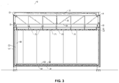
Figure 3 shows a lengthwise cut-away view of the module. -
Figure 4 shows a perspective detail of a pillar from the module. - According to the figures, one preferred embodiment of the proposed invention is described below.
- As shown in
Figures 1 to 3 , the industrialised module forming the invention comprises: - A roof made with three levels, a first level (1), followed by a second level (2) and finished with a third level (3)
- A series of pillars (16) joined at their upper ends to the third level (3) and at the lower end to the ground and to
- A lower slab (17) joined to the pillars and further supported by a series of central supports (18)
- The first level (1) of the roof comprises a perimeter frame (4) and a first ribbed sheet (5) whose function is to allow rainwater to run off via the pillars (16). The roof is lean-to, with a single pitch of 4%.
- The second level (2) of the roof comprises a first perimeter frame (8) preferably, of standard IPE steel profile and a series of first tubular crossbeams (9) on which a second ribbed sheet (10) is placed, leaving the first level (1) joined to the second level (2) by means of a series of side lattices (7) and intermediary lattices (6).
- The second ribbed sheet (10) may have a thickness of 0.6 mm and will serve to support the load for the upper reinforcement consisting of a cushion of sand bags with a thickness of 60 cm.
- The third roof level (3) comprises a second perimeter frame (11) and a series of second tubular crossbeams (12) under which thermal and acoustic insulation in mineral wool (13) is laid under which a waterproof wooden board (14) is laid, and in turn, under the latter, a series of folded sheet slats (15) forming a false ceiling.
- The facades and side walls are made with sandwich panels (19) formed by a steel sheet, followed by a core of high-density polyurethane foam, closed off with a second steel sheet. In one possible embodiment the thickness of the different elements might be as follows: for the external steel sheets a thickness of 0.5 mm; for the internal insulation, a thickness of 60 mm.
- This arrangement achieves 0.32 W/m2 K of heat insulation, between 30 and 35 DB of acoustic insulation depending on the frequency and a fire classification of B s3, d0.
- The sandwich panel (19) can be covered externally with a phenolic board (20) 6 mm in thickness, and internally by a pillar finish (21) in white lacquered sheet. The flooring is in synthetic wood parquet which in one possible embodiment might comprise:
- a wood laminate (22) of 7 mm in thickness
- followed by a fire-resistant MDF board (23) of 25 mm in thickness
- followed by mineral wool heat insulation (24) of 100 mm in thickness
- followed finally, a waterproof wooden board (25) of 8 mm in thickness.
- The entire interior can be protected with a skirting board (26).
-
Figure 4 shows a depiction of a pillar (16) which, as can be seen, is a hollow structure which allows concealed passage of downspouts for water gathered on the roof and accommodation of other installations running through the cavity of the facade walls. In turn, they act as a support for the ground and roof slabs which will be joined to them via bushings allowing the slab to be threaded along the pillar. At the upper end of each pillar (16) there is a connection head (16.1), while at the lower end there is a base (16.2) connecting to the ground and to the lower slab (17). - Other construction elements are:
Partition walls: Formed by sandwich panel sheet of 0.5 mm in thickness, polyurethane foam core of 60-40 mm in thickness and sheet of 0.5 mm in thickness. This arrangement achieves 0.46 W/m2 K of heat insulation, between 25 and 30 DB of acoustic insulation, depending on the frequency, and a fire classification of B s3 d0. - Exterior and interior doors: The exterior access door to the dwelling is provided in panelled aluminium with a safety lock. The interior doors envisaged are of aluminium frame with galvanised steel sheet, white with PVC handles.
- Windows: Sliding windows with 2 aluminium sheets and double glazing, thickness 4/6/4 m.
- Pack of sanitary appliances and taps. Sanitary appliances are in white porcelain, of the Roca brand or similar, with mixer taps in wash-hand basins and sinks and double taps in the shower. A toilet of the same material characteristics is included.
- Plumbing and electrical installations. The plumbing installations are made as per legislation using copper pipes. The predicted drainage is limited to evacuation from the toilet and kitchen sink by means of 90 mm diameter PVC pipes.
- All conduits will be hidden and the possibility is envisaged of installing an electric water heater as an improvement to ensure a supply of domestic hot water.
- Connections will be made by the fitter/developer. Drainage will be installed by the customer in the foundation bed.
- The electrical installation will be made with concealed corrugated pipe and fitted mechanisms and junctions. The sections of the conductor filament meet the specifications of the Low Voltage Electrotechnical Regulations (Reglamento Electrotécnico de Baja Tension) (RD 2143/1973), for a basic degree of electrification.
- Three circuits are installed:
- C1.- 10 amp lighting
- C2.- 16 amp sockets and general use
- C3.- Cooker 25 amps
- Having sufficiently described the nature of the present invention, and the means of implementing it, it is noted that within the same essence, it may be made in other embodiments differing in detail from that indicated herein as an example, and to which the protection obtained shall equally extend, provided that it does not alter, change or modify its basic principle.
Claims (7)
- Industrialised module for prefabricated housing solutions comprising:- a roof made with three levels, a first level (1), followed by a second level (2) and finished with a third level (3),- a series of pillars (16) joined at their upper ends to the third level (3) and at the lower end to the ground and- a lower slab (17) joined to the pillars and further supported by a series of central supports (18)
where;- the first level (1) of the roof comprises a perimeter frame (4) and a first ribbed sheet (5),- the second level (2) of the roof comprises a first perimeter frame (8) and a series of first tubular crossbeams (9) on which a second ribbed sheet (10) is positioned, leaving the first level (1) joined to the second level (2) by means of a series of side lattices (7) and intermediary lattices (6) and- the third roof level (3) comprises a second perimeter frame (11) and a series of second tubular crossbeams (12) under which thermal and acoustic insulation in mineral wool (13) is laid under which a waterproof wooden board (14) is laid, and in turn under the latter a series of folded sheet slats (15) forming a false ceiling. - Industrialised module for prefabricated housing solutions in accordance with Claim 1, characterised by the fact that the thickness of the second ribbed sheet (10) may be 0.6 mm and will serve to support the load for the upper reinforcement consisting of a cushion of sand bags with a thickness of 60 cm.
- Industrialised module for prefabricated housing solutions according to any of the above claims, characterised by the fact that the facades and side walls are made with sandwich panels (19) formed by a steel sheet, followed by a high-density polyurethane foam core, closed off by a second steel sheet.
- Industrialised module for prefabricated housing solutions in accordance with Claim 3, characterised by the fact that the thickness of the different elements of the sandwich panel (19) is as follows: for the external steel sheets, 0.5 mm; for the internal insulation, 60 mm.
- Industrialised module for prefabricated housing solutions in accordance with Claims 3 or 4, characterised by the fact that the sandwich panel (19) is externally covered by a phenolic board (20) of 6 mm in thickness, and internally by a pillar finish (21) in white lacquered sheet.
- Industrialised module for prefabricated housing solutions in accordance with any of the above claims, characterised by the fact that the module has flooring which is a synthetic wood parquet comprising:- a wood laminate (22) of 7 mm in thickness,- followed by a fire-resistant MDF board (23) of 25 mm in thickness,- followed by mineral wool heat insulation (24) of 100 mm in thickness- and finally, a waterproof wooden board (25) of 8 mm in thickness.
- Industrialised module for prefabricated housing solutions in accordance with any of the above claims, characterised by the fact that the pillars (16) have a hollow structure to accommodate downspouts and installations, having at their upper end a connection head (16.1), while at the lower end they have a base for connection (16.2) to the ground and to the lower slab (17).
Applications Claiming Priority (1)
| Application Number | Priority Date | Filing Date | Title |
|---|---|---|---|
| PCT/ES2017/070030 WO2018134449A1 (en) | 2017-01-18 | 2017-01-18 | Industrialised module for prefabricated housing solutions |
Publications (3)
| Publication Number | Publication Date |
|---|---|
| EP3456893A1 EP3456893A1 (en) | 2019-03-20 |
| EP3456893A4 EP3456893A4 (en) | 2020-01-15 |
| EP3456893B1 true EP3456893B1 (en) | 2020-12-09 |
Family
ID=62909094
Family Applications (1)
| Application Number | Title | Priority Date | Filing Date |
|---|---|---|---|
| EP17892646.5A Active EP3456893B1 (en) | 2017-01-18 | 2017-01-18 | Industrialised module for prefabricated housing solutions |
Country Status (3)
| Country | Link |
|---|---|
| EP (1) | EP3456893B1 (en) |
| ES (1) | ES2849923T3 (en) |
| WO (1) | WO2018134449A1 (en) |
Family Cites Families (9)
| Publication number | Priority date | Publication date | Assignee | Title |
|---|---|---|---|---|
| FR2267435A1 (en) * | 1974-04-12 | 1975-11-07 | Lemettre Gerard | Modular steel-framed building construction - has welded crowns joining posts, floor base and foundation |
| RO79813A (en) * | 1974-05-08 | 1982-09-09 | Industrielle De Constructions Mobiles,Fr | PREFABRICATED CONSTRUCTION WITH METAL STRUCTURE |
| US4534148A (en) * | 1983-04-22 | 1985-08-13 | Encon Products, Inc. | Adjustable roofing support spacer apparatus and erection method |
| US4512120A (en) * | 1982-02-24 | 1985-04-23 | Lindal Sir W | Modular home construction |
| US4570396A (en) * | 1983-11-09 | 1986-02-18 | Struben Francis L | Roof structure for mobile homes |
| US7827738B2 (en) * | 2006-08-26 | 2010-11-09 | Alexander Abrams | System for modular building construction |
| GB2465182B (en) * | 2008-11-07 | 2013-07-31 | Hesco Bastion Ltd | Protective shelter |
| US20110226166A1 (en) * | 2010-03-19 | 2011-09-22 | Recon International FZE | Overhead protection system |
| ES2398821B2 (en) * | 2011-07-12 | 2014-02-06 | Entreriver, S.A. | INDUSTRIALIZED PROCEDURE FOR CONSTRUCTION OF BUILDINGS AND PREFABRICATED SETS OF USE IN THIS PROCEDURE |
-
2017
- 2017-01-18 WO PCT/ES2017/070030 patent/WO2018134449A1/en unknown
- 2017-01-18 ES ES17892646T patent/ES2849923T3/en active Active
- 2017-01-18 EP EP17892646.5A patent/EP3456893B1/en active Active
Non-Patent Citations (1)
| Title |
|---|
| None * |
Also Published As
| Publication number | Publication date |
|---|---|
| EP3456893A4 (en) | 2020-01-15 |
| WO2018134449A1 (en) | 2018-07-26 |
| ES2849923T3 (en) | 2021-08-23 |
| EP3456893A1 (en) | 2019-03-20 |
Similar Documents
| Publication | Publication Date | Title |
|---|---|---|
| AU2021200954B2 (en) | Modular Building | |
| US11821196B2 (en) | Foldable building structures with utility channels and laminate enclosures | |
| US4759160A (en) | Prefabricated concrete buildings with monolithic roof, wall, and floor members | |
| JP2015513622A (en) | Adjustable height container | |
| US20190234063A1 (en) | Horizontal self-supporting formwork building system | |
| EP3456893B1 (en) | Industrialised module for prefabricated housing solutions | |
| RU2153047C2 (en) | Wall member and wall member system | |
| JP3196751U (en) | Wooden building and outer wall structure | |
| JP6427013B2 (en) | Wooden building and its outer wall structure | |
| JP2015209699A (en) | Wall structure and wooden building | |
| WO2023285301A1 (en) | Stackable and road-transportable micro modular house | |
| KR20150007121A (en) | two floor construction method and two floor system | |
| GR1010181B (en) | Prefabricated shed | |
| MXPA98001574A (en) | Prefabricated building building and rap assembly |
Legal Events
| Date | Code | Title | Description |
|---|---|---|---|
| STAA | Information on the status of an ep patent application or granted ep patent |
Free format text: STATUS: THE INTERNATIONAL PUBLICATION HAS BEEN MADE |
|
| PUAI | Public reference made under article 153(3) epc to a published international application that has entered the european phase |
Free format text: ORIGINAL CODE: 0009012 |
|
| STAA | Information on the status of an ep patent application or granted ep patent |
Free format text: STATUS: REQUEST FOR EXAMINATION WAS MADE |
|
| 17P | Request for examination filed |
Effective date: 20190124 |
|
| AK | Designated contracting states |
Kind code of ref document: A1 Designated state(s): AL AT BE BG CH CY CZ DE DK EE ES FI FR GB GR HR HU IE IS IT LI LT LU LV MC MK MT NL NO PL PT RO RS SE SI SK SM TR |
|
| AX | Request for extension of the european patent |
Extension state: BA ME |
|
| A4 | Supplementary search report drawn up and despatched |
Effective date: 20191213 |
|
| RIC1 | Information provided on ipc code assigned before grant |
Ipc: E04B 1/348 20060101ALI20191209BHEP Ipc: E04B 1/343 20060101ALN20191209BHEP Ipc: E04H 9/14 20060101AFI20191209BHEP |
|
| DAV | Request for validation of the european patent (deleted) | ||
| DAX | Request for extension of the european patent (deleted) | ||
| REG | Reference to a national code |
Ref country code: DE Ref legal event code: R079 Ref document number: 602017029460 Country of ref document: DE Free format text: PREVIOUS MAIN CLASS: E04B0001343000 Ipc: E04H0009140000 |
|
| RIC1 | Information provided on ipc code assigned before grant |
Ipc: E04H 9/14 20060101AFI20200430BHEP Ipc: E04B 1/348 20060101ALI20200430BHEP Ipc: E04B 1/343 20060101ALN20200430BHEP |
|
| GRAP | Despatch of communication of intention to grant a patent |
Free format text: ORIGINAL CODE: EPIDOSNIGR1 |
|
| STAA | Information on the status of an ep patent application or granted ep patent |
Free format text: STATUS: GRANT OF PATENT IS INTENDED |
|
| INTG | Intention to grant announced |
Effective date: 20200605 |
|
| GRAS | Grant fee paid |
Free format text: ORIGINAL CODE: EPIDOSNIGR3 |
|
| GRAA | (expected) grant |
Free format text: ORIGINAL CODE: 0009210 |
|
| STAA | Information on the status of an ep patent application or granted ep patent |
Free format text: STATUS: THE PATENT HAS BEEN GRANTED |
|
| AK | Designated contracting states |
Kind code of ref document: B1 Designated state(s): AL AT BE BG CH CY CZ DE DK EE ES FI FR GB GR HR HU IE IS IT LI LT LU LV MC MK MT NL NO PL PT RO RS SE SI SK SM TR |
|
| REG | Reference to a national code |
Ref country code: GB Ref legal event code: FG4D |
|
| REG | Reference to a national code |
Ref country code: AT Ref legal event code: REF Ref document number: 1343609 Country of ref document: AT Kind code of ref document: T Effective date: 20201215 Ref country code: CH Ref legal event code: EP |
|
| REG | Reference to a national code |
Ref country code: DE Ref legal event code: R096 Ref document number: 602017029460 Country of ref document: DE |
|
| REG | Reference to a national code |
Ref country code: IE Ref legal event code: FG4D |
|
| PG25 | Lapsed in a contracting state [announced via postgrant information from national office to epo] |
Ref country code: NO Free format text: LAPSE BECAUSE OF FAILURE TO SUBMIT A TRANSLATION OF THE DESCRIPTION OR TO PAY THE FEE WITHIN THE PRESCRIBED TIME-LIMIT Effective date: 20210309 Ref country code: GR Free format text: LAPSE BECAUSE OF FAILURE TO SUBMIT A TRANSLATION OF THE DESCRIPTION OR TO PAY THE FEE WITHIN THE PRESCRIBED TIME-LIMIT Effective date: 20210310 Ref country code: RS Free format text: LAPSE BECAUSE OF FAILURE TO SUBMIT A TRANSLATION OF THE DESCRIPTION OR TO PAY THE FEE WITHIN THE PRESCRIBED TIME-LIMIT Effective date: 20201209 Ref country code: FI Free format text: LAPSE BECAUSE OF FAILURE TO SUBMIT A TRANSLATION OF THE DESCRIPTION OR TO PAY THE FEE WITHIN THE PRESCRIBED TIME-LIMIT Effective date: 20201209 |
|
| REG | Reference to a national code |
Ref country code: AT Ref legal event code: MK05 Ref document number: 1343609 Country of ref document: AT Kind code of ref document: T Effective date: 20201209 |
|
| PG25 | Lapsed in a contracting state [announced via postgrant information from national office to epo] |
Ref country code: BG Free format text: LAPSE BECAUSE OF FAILURE TO SUBMIT A TRANSLATION OF THE DESCRIPTION OR TO PAY THE FEE WITHIN THE PRESCRIBED TIME-LIMIT Effective date: 20210309 Ref country code: SE Free format text: LAPSE BECAUSE OF FAILURE TO SUBMIT A TRANSLATION OF THE DESCRIPTION OR TO PAY THE FEE WITHIN THE PRESCRIBED TIME-LIMIT Effective date: 20201209 Ref country code: LV Free format text: LAPSE BECAUSE OF FAILURE TO SUBMIT A TRANSLATION OF THE DESCRIPTION OR TO PAY THE FEE WITHIN THE PRESCRIBED TIME-LIMIT Effective date: 20201209 |
|
| REG | Reference to a national code |
Ref country code: NL Ref legal event code: MP Effective date: 20201209 |
|
| PG25 | Lapsed in a contracting state [announced via postgrant information from national office to epo] |
Ref country code: HR Free format text: LAPSE BECAUSE OF FAILURE TO SUBMIT A TRANSLATION OF THE DESCRIPTION OR TO PAY THE FEE WITHIN THE PRESCRIBED TIME-LIMIT Effective date: 20201209 Ref country code: NL Free format text: LAPSE BECAUSE OF FAILURE TO SUBMIT A TRANSLATION OF THE DESCRIPTION OR TO PAY THE FEE WITHIN THE PRESCRIBED TIME-LIMIT Effective date: 20201209 |
|
| REG | Reference to a national code |
Ref country code: LT Ref legal event code: MG9D |
|
| PG25 | Lapsed in a contracting state [announced via postgrant information from national office to epo] |
Ref country code: CZ Free format text: LAPSE BECAUSE OF FAILURE TO SUBMIT A TRANSLATION OF THE DESCRIPTION OR TO PAY THE FEE WITHIN THE PRESCRIBED TIME-LIMIT Effective date: 20201209 Ref country code: EE Free format text: LAPSE BECAUSE OF FAILURE TO SUBMIT A TRANSLATION OF THE DESCRIPTION OR TO PAY THE FEE WITHIN THE PRESCRIBED TIME-LIMIT Effective date: 20201209 Ref country code: LT Free format text: LAPSE BECAUSE OF FAILURE TO SUBMIT A TRANSLATION OF THE DESCRIPTION OR TO PAY THE FEE WITHIN THE PRESCRIBED TIME-LIMIT Effective date: 20201209 Ref country code: SM Free format text: LAPSE BECAUSE OF FAILURE TO SUBMIT A TRANSLATION OF THE DESCRIPTION OR TO PAY THE FEE WITHIN THE PRESCRIBED TIME-LIMIT Effective date: 20201209 Ref country code: PT Free format text: LAPSE BECAUSE OF FAILURE TO SUBMIT A TRANSLATION OF THE DESCRIPTION OR TO PAY THE FEE WITHIN THE PRESCRIBED TIME-LIMIT Effective date: 20210409 Ref country code: RO Free format text: LAPSE BECAUSE OF FAILURE TO SUBMIT A TRANSLATION OF THE DESCRIPTION OR TO PAY THE FEE WITHIN THE PRESCRIBED TIME-LIMIT Effective date: 20201209 Ref country code: SK Free format text: LAPSE BECAUSE OF FAILURE TO SUBMIT A TRANSLATION OF THE DESCRIPTION OR TO PAY THE FEE WITHIN THE PRESCRIBED TIME-LIMIT Effective date: 20201209 |
|
| REG | Reference to a national code |
Ref country code: ES Ref legal event code: FG2A Ref document number: 2849923 Country of ref document: ES Kind code of ref document: T3 Effective date: 20210823 |
|
| PG25 | Lapsed in a contracting state [announced via postgrant information from national office to epo] |
Ref country code: AT Free format text: LAPSE BECAUSE OF FAILURE TO SUBMIT A TRANSLATION OF THE DESCRIPTION OR TO PAY THE FEE WITHIN THE PRESCRIBED TIME-LIMIT Effective date: 20201209 Ref country code: PL Free format text: LAPSE BECAUSE OF FAILURE TO SUBMIT A TRANSLATION OF THE DESCRIPTION OR TO PAY THE FEE WITHIN THE PRESCRIBED TIME-LIMIT Effective date: 20201209 |
|
| REG | Reference to a national code |
Ref country code: CH Ref legal event code: PL |
|
| REG | Reference to a national code |
Ref country code: DE Ref legal event code: R097 Ref document number: 602017029460 Country of ref document: DE |
|
| PG25 | Lapsed in a contracting state [announced via postgrant information from national office to epo] |
Ref country code: MC Free format text: LAPSE BECAUSE OF FAILURE TO SUBMIT A TRANSLATION OF THE DESCRIPTION OR TO PAY THE FEE WITHIN THE PRESCRIBED TIME-LIMIT Effective date: 20201209 Ref country code: LU Free format text: LAPSE BECAUSE OF NON-PAYMENT OF DUE FEES Effective date: 20210118 Ref country code: IS Free format text: LAPSE BECAUSE OF FAILURE TO SUBMIT A TRANSLATION OF THE DESCRIPTION OR TO PAY THE FEE WITHIN THE PRESCRIBED TIME-LIMIT Effective date: 20210409 |
|
| REG | Reference to a national code |
Ref country code: BE Ref legal event code: MM Effective date: 20210131 |
|
| PLBE | No opposition filed within time limit |
Free format text: ORIGINAL CODE: 0009261 |
|
| STAA | Information on the status of an ep patent application or granted ep patent |
Free format text: STATUS: NO OPPOSITION FILED WITHIN TIME LIMIT |
|
| PG25 | Lapsed in a contracting state [announced via postgrant information from national office to epo] |
Ref country code: AL Free format text: LAPSE BECAUSE OF FAILURE TO SUBMIT A TRANSLATION OF THE DESCRIPTION OR TO PAY THE FEE WITHIN THE PRESCRIBED TIME-LIMIT Effective date: 20201209 |
|
| 26N | No opposition filed |
Effective date: 20210910 |
|
| GBPC | Gb: european patent ceased through non-payment of renewal fee |
Effective date: 20210309 |
|
| PG25 | Lapsed in a contracting state [announced via postgrant information from national office to epo] |
Ref country code: SI Free format text: LAPSE BECAUSE OF FAILURE TO SUBMIT A TRANSLATION OF THE DESCRIPTION OR TO PAY THE FEE WITHIN THE PRESCRIBED TIME-LIMIT Effective date: 20201209 Ref country code: CH Free format text: LAPSE BECAUSE OF NON-PAYMENT OF DUE FEES Effective date: 20210131 Ref country code: DK Free format text: LAPSE BECAUSE OF FAILURE TO SUBMIT A TRANSLATION OF THE DESCRIPTION OR TO PAY THE FEE WITHIN THE PRESCRIBED TIME-LIMIT Effective date: 20201209 Ref country code: LI Free format text: LAPSE BECAUSE OF NON-PAYMENT OF DUE FEES Effective date: 20210131 |
|
| PG25 | Lapsed in a contracting state [announced via postgrant information from national office to epo] |
Ref country code: GB Free format text: LAPSE BECAUSE OF NON-PAYMENT OF DUE FEES Effective date: 20210309 Ref country code: IE Free format text: LAPSE BECAUSE OF NON-PAYMENT OF DUE FEES Effective date: 20210118 |
|
| PG25 | Lapsed in a contracting state [announced via postgrant information from national office to epo] |
Ref country code: IS Free format text: LAPSE BECAUSE OF FAILURE TO SUBMIT A TRANSLATION OF THE DESCRIPTION OR TO PAY THE FEE WITHIN THE PRESCRIBED TIME-LIMIT Effective date: 20210409 |
|
| PG25 | Lapsed in a contracting state [announced via postgrant information from national office to epo] |
Ref country code: BE Free format text: LAPSE BECAUSE OF NON-PAYMENT OF DUE FEES Effective date: 20210131 |
|
| PGFP | Annual fee paid to national office [announced via postgrant information from national office to epo] |
Ref country code: FR Payment date: 20230125 Year of fee payment: 7 Ref country code: ES Payment date: 20230206 Year of fee payment: 7 |
|
| PGFP | Annual fee paid to national office [announced via postgrant information from national office to epo] |
Ref country code: IT Payment date: 20230125 Year of fee payment: 7 Ref country code: DE Payment date: 20230126 Year of fee payment: 7 |
|
| PG25 | Lapsed in a contracting state [announced via postgrant information from national office to epo] |
Ref country code: CY Free format text: LAPSE BECAUSE OF FAILURE TO SUBMIT A TRANSLATION OF THE DESCRIPTION OR TO PAY THE FEE WITHIN THE PRESCRIBED TIME-LIMIT Effective date: 20201209 |
|
| PG25 | Lapsed in a contracting state [announced via postgrant information from national office to epo] |
Ref country code: HU Free format text: LAPSE BECAUSE OF FAILURE TO SUBMIT A TRANSLATION OF THE DESCRIPTION OR TO PAY THE FEE WITHIN THE PRESCRIBED TIME-LIMIT; INVALID AB INITIO Effective date: 20170118 |