EP3456876A1 - Wire rope - Google Patents
Wire rope Download PDFInfo
- Publication number
- EP3456876A1 EP3456876A1 EP16829223.3A EP16829223A EP3456876A1 EP 3456876 A1 EP3456876 A1 EP 3456876A1 EP 16829223 A EP16829223 A EP 16829223A EP 3456876 A1 EP3456876 A1 EP 3456876A1
- Authority
- EP
- European Patent Office
- Prior art keywords
- wire
- metal element
- wire rope
- wires
- cross
- Prior art date
- Legal status (The legal status is an assumption and is not a legal conclusion. Google has not performed a legal analysis and makes no representation as to the accuracy of the status listed.)
- Withdrawn
Links
- 229910052751 metal Inorganic materials 0.000 claims abstract description 94
- 239000002184 metal Substances 0.000 claims abstract description 94
- 238000004804 winding Methods 0.000 claims description 3
- 239000004519 grease Substances 0.000 abstract description 9
- 239000000463 material Substances 0.000 description 9
- 230000002093 peripheral effect Effects 0.000 description 9
- 229910001220 stainless steel Inorganic materials 0.000 description 9
- 239000010935 stainless steel Substances 0.000 description 9
- 230000000694 effects Effects 0.000 description 5
- 238000005299 abrasion Methods 0.000 description 3
- 230000003247 decreasing effect Effects 0.000 description 3
- 229910052782 aluminium Inorganic materials 0.000 description 2
- XAGFODPZIPBFFR-UHFFFAOYSA-N aluminium Chemical compound [Al] XAGFODPZIPBFFR-UHFFFAOYSA-N 0.000 description 2
- 239000011248 coating agent Substances 0.000 description 2
- 238000000576 coating method Methods 0.000 description 2
- 239000011347 resin Substances 0.000 description 2
- 229920005989 resin Polymers 0.000 description 2
- WFKWXMTUELFFGS-UHFFFAOYSA-N tungsten Chemical compound [W] WFKWXMTUELFFGS-UHFFFAOYSA-N 0.000 description 2
- 229910052721 tungsten Inorganic materials 0.000 description 2
- 239000010937 tungsten Substances 0.000 description 2
- 238000005452 bending Methods 0.000 description 1
- 238000002474 experimental method Methods 0.000 description 1
- 230000001771 impaired effect Effects 0.000 description 1
- 239000010687 lubricating oil Substances 0.000 description 1
- 238000004519 manufacturing process Methods 0.000 description 1
- 238000000034 method Methods 0.000 description 1
- 238000012986 modification Methods 0.000 description 1
- 230000004048 modification Effects 0.000 description 1
- 238000007789 sealing Methods 0.000 description 1
Images




Classifications
-
- D—TEXTILES; PAPER
- D07—ROPES; CABLES OTHER THAN ELECTRIC
- D07B—ROPES OR CABLES IN GENERAL
- D07B1/00—Constructional features of ropes or cables
- D07B1/06—Ropes or cables built-up from metal wires, e.g. of section wires around a hemp core
- D07B1/0606—Reinforcing cords for rubber or plastic articles
- D07B1/0646—Reinforcing cords for rubber or plastic articles comprising longitudinally preformed wires
- D07B1/0653—Reinforcing cords for rubber or plastic articles comprising longitudinally preformed wires in the core
-
- D—TEXTILES; PAPER
- D07—ROPES; CABLES OTHER THAN ELECTRIC
- D07B—ROPES OR CABLES IN GENERAL
- D07B1/00—Constructional features of ropes or cables
- D07B1/06—Ropes or cables built-up from metal wires, e.g. of section wires around a hemp core
- D07B1/0693—Ropes or cables built-up from metal wires, e.g. of section wires around a hemp core having a strand configuration
-
- D—TEXTILES; PAPER
- D07—ROPES; CABLES OTHER THAN ELECTRIC
- D07B—ROPES OR CABLES IN GENERAL
- D07B1/00—Constructional features of ropes or cables
-
- D—TEXTILES; PAPER
- D07—ROPES; CABLES OTHER THAN ELECTRIC
- D07B—ROPES OR CABLES IN GENERAL
- D07B1/00—Constructional features of ropes or cables
- D07B1/06—Ropes or cables built-up from metal wires, e.g. of section wires around a hemp core
- D07B1/0606—Reinforcing cords for rubber or plastic articles
- D07B1/066—Reinforcing cords for rubber or plastic articles the wires being made from special alloy or special steel composition
-
- D—TEXTILES; PAPER
- D07—ROPES; CABLES OTHER THAN ELECTRIC
- D07B—ROPES OR CABLES IN GENERAL
- D07B1/00—Constructional features of ropes or cables
- D07B1/06—Ropes or cables built-up from metal wires, e.g. of section wires around a hemp core
- D07B1/0673—Ropes or cables built-up from metal wires, e.g. of section wires around a hemp core having a rope configuration
- D07B1/068—Ropes or cables built-up from metal wires, e.g. of section wires around a hemp core having a rope configuration characterised by the strand design
-
- A—HUMAN NECESSITIES
- A61—MEDICAL OR VETERINARY SCIENCE; HYGIENE
- A61M—DEVICES FOR INTRODUCING MEDIA INTO, OR ONTO, THE BODY; DEVICES FOR TRANSDUCING BODY MEDIA OR FOR TAKING MEDIA FROM THE BODY; DEVICES FOR PRODUCING OR ENDING SLEEP OR STUPOR
- A61M25/00—Catheters; Hollow probes
- A61M25/01—Introducing, guiding, advancing, emplacing or holding catheters
- A61M25/09—Guide wires
- A61M2025/09191—Guide wires made of twisted wires
-
- D—TEXTILES; PAPER
- D07—ROPES; CABLES OTHER THAN ELECTRIC
- D07B—ROPES OR CABLES IN GENERAL
- D07B2201/00—Ropes or cables
- D07B2201/20—Rope or cable components
- D07B2201/2001—Wires or filaments
- D07B2201/2009—Wires or filaments characterised by the materials used
-
- D—TEXTILES; PAPER
- D07—ROPES; CABLES OTHER THAN ELECTRIC
- D07B—ROPES OR CABLES IN GENERAL
- D07B2201/00—Ropes or cables
- D07B2201/20—Rope or cable components
- D07B2201/2001—Wires or filaments
- D07B2201/2014—Compound wires or compound filaments
-
- D—TEXTILES; PAPER
- D07—ROPES; CABLES OTHER THAN ELECTRIC
- D07B—ROPES OR CABLES IN GENERAL
- D07B2201/00—Ropes or cables
- D07B2201/20—Rope or cable components
- D07B2201/2015—Strands
- D07B2201/2019—Strands pressed to shape
-
- D—TEXTILES; PAPER
- D07—ROPES; CABLES OTHER THAN ELECTRIC
- D07B—ROPES OR CABLES IN GENERAL
- D07B2201/00—Ropes or cables
- D07B2201/20—Rope or cable components
- D07B2201/2047—Cores
- D07B2201/2052—Cores characterised by their structure
- D07B2201/2059—Cores characterised by their structure comprising wires
-
- D—TEXTILES; PAPER
- D07—ROPES; CABLES OTHER THAN ELECTRIC
- D07B—ROPES OR CABLES IN GENERAL
- D07B2201/00—Ropes or cables
- D07B2201/20—Rope or cable components
- D07B2201/2047—Cores
- D07B2201/2066—Cores characterised by the materials used
-
- D—TEXTILES; PAPER
- D07—ROPES; CABLES OTHER THAN ELECTRIC
- D07B—ROPES OR CABLES IN GENERAL
- D07B2207/00—Rope or cable making machines
- D07B2207/40—Machine components
- D07B2207/404—Heat treating devices; Corresponding methods
- D07B2207/4045—Heat treating devices; Corresponding methods to change the crystal structure of the load bearing material
-
- D—TEXTILES; PAPER
- D07—ROPES; CABLES OTHER THAN ELECTRIC
- D07B—ROPES OR CABLES IN GENERAL
- D07B5/00—Making ropes or cables from special materials or of particular form
- D07B5/007—Making ropes or cables from special materials or of particular form comprising postformed and thereby radially plastically deformed elements
Definitions
- the present invention relates to a wire rope comprising multiple metal element wires.
- wire ropes have been known in each of which multiple metal element wires are twisted.
- wire ropes have advantages such as excellent impact resistance and good flexibility as compared with a single metal element wire.
- wire ropes are often subjected to repeated bending, and thus desirably have good durability under such usage conditions.
- Patent Document 1 describes an aluminum twisted wire (a wire rope) in which spaces between twisted wires inside the outermost aluminum twisted wire layer 14 is filled with grease 6 to improve its life time (see Fig. 1 and the like).
- Patent Document 2 describes a twisted wire rope having an improved life time, which can be prepared by forming an uneven surface on each surface of multiple metal element wires 16, and forming element twisted wires 17 by twisting the multiple metal element wires 16 each having the uneven surface, and twisting the element twisted wires 17 and then applying a resin coating 18 therearound, and filling spaces between the resin coating 18 and the element twisted wires 17 with grease (see Fig. 2 and others).
- Reference Document 3 describes an inner wire rope having an improved abrasion resistance and the like, which can be prepared by subjecting side strands to deforestation processing to make surface contacts between a core strand and the side strands, and sealing lubricating oil between the core strand and the side strands (see Fig. 1 and the like).
- An object of the present invention is to provide a wire rope having an improved durability without use of grease thereinside, in particular a wire rope with an improved durability which can be used in a medical device to be inserted into a patient's body.
- a first aspect of the present invention is characterized by a wire rope formed by winding multiple metal element wires, in which at least one special metal element wire among the multiple metal element wires has a hardness of the outer periphery in a cross-section higher than that of the center in that cross-section.
- a second aspect of the present invention is characterized by the wire rope according to the first aspect of the invention, in which the at least one special metal element wire is arranged at the center.
- a third aspect of the present invention is characterized by the wire rope according to the second aspect of the invention, in which the multiple metal element wires consisting only of the at least one special metal element wire and multiple side metal element wires making contact with the special metal element wire.
- a fourth aspect of the present invention is characterized by the wire rope according to the third aspect of the invention, in which the at least one special metal element wire has a circular cross-section, and the multiple side metal element wires each have an approximately trapezoidal cross-section.
- a fifth aspect of the present invention is characterized by a wire rope formed by twisting a plurality of wire ropes according to the fourth aspect of the invention.
- a sixth aspect of the present invention is characterized by the wire rope according to the first aspect of the invention, in which the at least one special metal element wire comprises multiple special metal element wires, and a twisted wire in which the multiple special metal element wires are twisted is arranged at the center.
- the first aspect of the present invention provides a wire rope formed by spirally winding multiple metal element wires, in which at least one special metal element wire among the multiple metal element wires has a hardness of the outer periphery in a cross-section higher than that of the center in that cross-section. This can provide an improved durability without use of grease thereinside, enabling its use in a medical device.
- the second aspect of the invention provides the wire rope according to the first aspect of the invention, in which the at least one special metal element wire is arranged at the center of the wire rope. This can further improve durability in addition to the effect of the first aspect of the invention.
- the third aspect of the invention provides the wire rope according to the second aspect of the invention, in which the multiple metal element wires consist only of the at least one special metal element wire, and multiple side metal element wires making contacts with the at least one special metal element wire. This can further improve durability in addition to the effect of the second aspect of the invention.
- the fourth aspect of the invention provides the wire rope according to the third aspect of the invention, in which the at least one special metal element wire has a circular cross-section, and the multiple side metal element wires each have an approximately trapezoidal cross-section. This can further improve durability in addition to the effect of the third aspect of the invention.
- the fifth aspect of the invention provides a wire rope formed by twisting a plurality of wire ropes according to the fourth aspect. This can further improve durability.
- the sixth aspect of the invention provides the wire rope according to the first aspect of the invention, in which the at least one special metal element wire comprises multiple special metal element wires, and a twisted wire in which the multiple special metal element wires are twisted is arranged at the center. This can improve flexibility in addition to the effect of the first aspect of the invention.
- Fig. 1 shows a cross-sectional view of the wire rope according to the first embodiment of the present invention.
- Fig. 2 shows a first hardness distribution of a cross-section of a special metal element wire used for the wire rope according to first embodiment.
- Fig. 3 shows a second hardness distribution of a cross-section of a special metal element wire used for the wire rope according to first embodiment.
- a wire rope 1 comprises a core wire 3 (which corresponds to the "special metal element wire” according to the present invention) located at the center, and 6 side wires 5 (5a, 5b, 5c, 5d, 5e, and 5f) wound around the core wire 3.
- the core wire 3 is a metal element wire having a circular cross-section extending from the front end to the base end through the center of the wire rope 1.
- the material of the core wire 3 is no particular limitation for the material of the core wire 3, but stainless steel is used in the present embodiment.
- the core wire 3 has a hardness of the peripheral part in a cross-section higher than that of the center in the cross-section. That is, the core wire 3 is configured to have a structure where only the surface of the core wire 3 is hardened, but the inside of the core wire 3 is not hardened. This structure successfully serves not only to maintain the flexibility of the core wire 3 but also to improve the resistance to abrasion due to contacts with the side wires 5.
- the structure in which only the surface of the core wire 3 is hardened, but the inside of the core wire 3 is not hardened may be, for example, a structure in which the hardness of the core wire 3 increases in the second-order fashion toward the outer periphery from the center in a cross-section of the wire rope 1 as shown in Fig. 2 , or may be a structure in which the hardness increases in the linear fashion, or may be a structure in which the hardness of the core wire 3 shows a flat region in the vicinity of the center of the wire rope 1, and increases toward the outer periphery from the flat region as shown in Fig. 3 .
- the hardness of the core wire 3 in Fig. 2 is about 650 HV at the center in a cross-section of the wire rope 1 while it is about 700 HV at the outer periphery, showing a difference of 50 HV.
- the hardness of the core wire 3 in Fig. 3 is constant at about 650 HV in the vicinity of the center of the wire rope 1 while it is about 700 HV at the outer periphery, showing a difference of 50 HV.
- the side wires 5 (5a, 5b, 5c, 5d, 5e, and 5f), which are metal element wires each having a circular cross-section, are spirally wound around the core wire 3 in the longitudinal direction.
- the material of the side wires 5 (5a, 5b, 5c, 5d, 5e, and 5f) as well, but stainless steel is used in the present embodiment. In addition to this, tungsten may also be used.
- the core wire 3 having a hardness of the peripheral part in a cross-section higher than that of the center is arranged at the center of the wire rope 1 such that the multiple wires 5 (5a, 5b, 5c, 5d, 5e, and 5f) all make contacts with the core wire 3. This can improve the durability of the wire rope.
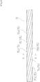
- Fig. 4 shows a side view of a wire rope according to the second embodiment
- Fig. 5 shows a cross-sectional view at A-A in Fig. 4 .
- a wire rope 11 comprises a core wire 3 located at the center, and 6 side wires 15 (15a, 15b, 15c, 15d, 15e, and 15f) wound around the core wire 3.
- the side wires 15 (15a, 15b, 15c, 15d, 15e, and 15f), which are metal element wires each deforestation-processed into an approximately trapezoidal shape, are spirally wound around the core wire 3 in the longitudinal direction.
- the material of the side wires 15 (15a, 15b, 15c, 15d, 15e, and 15f), but stainless steel is used in the present embodiment. In addition to this, tungsten may also be used.
- the core wire 3 having a hardness of the peripheral part in a cross-section higher than that of the center is arranged at the center of the wire rope 1 such that the 6 side wires 5 (5a, 5b, 5c, 5d, 5e, and 5f) configured to be approximately trapezoidal and each having an approximately trapezoidal cross-section all make surface contacts with the core wire 3, and the wire rope 11 is configured to have an approximately circular cross-sectional outer periphery.
- This can improve not only the torque transmissibility of the wire rope 11 (the torque transmissibility to one end of a wire rope when the other end of the wire rope is rotated) but also the durability of the wire rope.
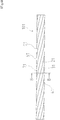
- Fig. 6 shows a side view of a wire rope according to the third embodiment
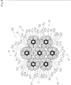
- Fig. 7 shows a cross-sectional view at B-B in Fig. 6 .
- a wire rope 101 comprises the core wire rope 11 according to the second embodiment located at the center, and 6 side wire ropes 21, 31, 41, 51, 61, and 71 wound around the core wire rope 11.
- the side wire ropes 21, 31, 41, 51, 61, and 71 each have a similar structure to that of the core wire rope 11, and are spirally wound around the core wire rope 11 in the longitudinal direction.
- the side wire rope 21 comprises a core wire 3a located at the center (which corresponds to the "special metal element wire” according to the present invention) and 6 side wires 25 (25a, 25b, 25c, 25d, 25e, and 25f) wound around the core wire 3a
- the side wire rope 31 comprises a core wire 3b (which corresponds to the "special metal element wire” according to the present invention) located at the center and 6 side wires 35 (35a, 35b, 35c, 35d, 35e, and 35f) wound around the core wire 3b
- the side wire rope 41 comprises a core wire 3c (which corresponds to the "special metal element wire” according to the present invention) located at the center and 6 side wires 45 (45a, 45b, 45c, 45d, 45e, and 45f) wound around the core wire 3c.
- the side wire rope 51 comprises a core wire 3d (which corresponds to the "special metal element wire” according to the present invention) located at the center and 6 side wires 55 (55a, 55b, 55c, 55d, 55e, and 55f) wound around the core wire 3d
- the side wire rope 61 comprises a core wire 3e (which corresponds to the "special metal element wire” according to the present invention) located at the center and 6 side wires 65 (65a, 65b, 65c, 65d, 65e, and 65f) wound around the core wire 3e
- the side wire rope 71 comprises a core wire of 3f (which corresponds to the "special metal element wire” according to the present invention) located at the center and 6 side wires 75 (75a, 75b, 75c, 75d, 75e, and 75f) wound around the core wire 3f.
- the wire rope 101 is formed by twisting a plurality of wire ropes in each of which a core wire having a hardness of the peripheral part in a cross-section higher than that of the center is arranged at the center such that 6 side wires each having an approximately trapezoidal cross-section all make contacts with the core wire, each wire rope being configured to have an approximately circular cross-sectional outer periphery.
- This can further improve not only the torque transmissibility of the wire rope 101 (the torque transmissibility to one end of a wire rope when the other end of the wire rope is rotated) but also the durability of the wire rope.
- Fig. 8 shows a cross-sectional view of a wire rope according to the fourth embodiment.
- a wire rope 81 comprises a core twisted wire 13 located at the center, 4 side wires 82 arranged at the outside of the core twisted wire 13, and 8 side wires 85 wound around the core twisted wire 13 and the side wires 82.
- the core twisted wire 13 comprises 4 metal element wires (13a, 13b, 13c, and 13d (each corresponds to the "special metal element wire” according to the present invention)), and each metal element wire has a circular cross-section.
- metal element wires 13a, 13b, 13c, and 13d
- stainless steel is used in the present embodiment.
- each metal element wire (13a, 13b, 13c, and 13d), which constitutes the core twisted wire 13 each have a hardness of the peripheral part in a cross-section higher than that of the central part in the cross-section. That is, each metal element wire (13a, 13b, 13c, and 13d) has a structure in which only the surface of the metal element wire is hardened, but the inside of the metal element wire is not hardened. Further, the core twisted wire 13 is formed by twisting four of this metal element wire. This can improve the flexibility of the core twisted wire 13, and can improve the durability.
- side wires 82 (82a, 82b, 82c, and 82d), each of which has a circular cross-section, and comprises metal element wires each having a diameter smaller than that of each metal element wire (13a, 13b, 13c, and 13d) of the core twisted wire 13, is arranged at the outside of the core twisted wire 13.
- the material of the side wires 82 (82a, 82b, 82c, and 82d)
- stainless steel is used in the present embodiment.
- 8 side wires 85 (85a, 85b, 85c, 85d, 85e, 85f, 85g, and 85h), which are metal element wires each having a circular cross-section, are arranged at the outside of the core twisted wire 13 and the side wires 82 (82a, 82b, 82c, and 82d).
- the material of the side wires 85 (85a, 85b, 85c, 85d, 85e, 85f, 85g, and 85h), but stainless steel is used in the present embodiment.
- the core twisted wire 13 formed by twisting 4 metal element wires each having a hardness of the peripheral part in a cross-section higher than that of the central part is arranged at the center. This can further improve the flexibility of the wire rope 81, and can improve the durability.
- FIG. 9 shows a cross-sectional view of a wire rope according to the fifth embodiment.
- a wire rope 91 comprises a core twisted wire 23 located at the center, 4 side wires 92 arranged at the outside of the core twisted wire 23, and 8 side wires 95 wound around the core twisted wire 23 and the side wires 92.
- the core twisted wire 23 comprises 4 metal element wires (23a, 23b, 23c, and 23d (each corresponds to the "special metal element wire” according to the present invention)), and each of the metal element wire has a circular cross-section.
- metal element wires 23a, 23b, 23c, and 23d
- stainless steel is used in the present embodiment.
- the metal element wire 23d has a hardness of the peripheral part in a cross-section higher than that of the center in the cross-section. That is, the metal element wire 23d is configured to have a structure in which only the surface of the metal element wire is hardened, but the inside of the metal element wire is not hardened.
- the metal element wires 23a, 23b, and 23c each have an approximately constant hardness profile throughout a cross-section.
- the core twisted wire 23 is formed by twisting the 4 metal element wires. This can further improve the flexibility of the core twisted wire 23.
- 4 side wires 92 (92a, 92b, 92c, and 92d), each of which has a circular cross-section, and comprises metal element wires each having a diameter smaller than that of each metal element wires (23a, 23b, 23c, and 23d) of the core twisted wire 23, is arranged at the outside of the core twisted wire 23.
- the material of the side wires 92 (92a, 92b, 92c, and 92d)
- stainless steel is used in the present embodiment.
- side wires 95 (95a, 95b, 95c, 95d, 95e, 95f, 95g, and 95h), which are metal element wires each having a circular cross-section, are arranged at the outside of the core twisted wire 23 and the side wire 92 (92a, 92b, 92c, and 92d).
- the material of the side wires 95 (95a, 95b, 95c, 95d, 95e, 95f, 95g, and 95h), but stainless steel is used in the present embodiment.
- the core twisted wire 23 formed with the metal element wires each having a hardness of the peripheral part in a cross-section higher than that of the central part is arranged at the center of the wire rope 91. This can improve the flexibility and durability of the wire rope 91.
- the side wires 5, 15, 25, 35, 45, 55, 65, and 75 are each formed with 6 metal element wires.
- the number of metal element wires is, however, not limited to 6, and 3 or more may be sufficient.
- the core twisted wires 13 and 23 are each formed by twisting 4 metal element wires.
- the number of metal element wires is, however, not limited to 4, and two or more may be sufficient.
- the side wires 85 and 95 each comprise 8 metal element wires.
- the number of metal element wire is, however, not limited to 8, and any number may be used as long as the core twisted wire 13 or 23 is covered.
- the side wires 82 and 92 are provided, but the side wires 82 and 92 may not be present.
Landscapes
- Ropes Or Cables (AREA)
Abstract
Description
- The present invention relates to a wire rope comprising multiple metal element wires.
- To date, wire ropes have been known in each of which multiple metal element wires are twisted. In general, wire ropes have advantages such as excellent impact resistance and good flexibility as compared with a single metal element wire. Further, wire ropes are often subjected to repeated bending, and thus desirably have good durability under such usage conditions.
- For example, Patent Document 1 describes an aluminum twisted wire (a wire rope) in which spaces between twisted wires inside the outermost aluminum twisted wire layer 14 is filled with grease 6 to improve its life time (see
Fig. 1 and the like). - Further, Patent Document 2 describes a twisted wire rope having an improved life time, which can be prepared by forming an uneven surface on each surface of multiple metal element wires 16, and forming element twisted wires 17 by twisting the multiple metal element wires 16 each having the uneven surface, and twisting the element twisted wires 17 and then applying a resin coating 18 therearound, and filling spaces between the resin coating 18 and the element twisted wires 17 with grease (see
Fig. 2 and others). - Further,
Reference Document 3 describes an inner wire rope having an improved abrasion resistance and the like, which can be prepared by subjecting side strands to deforestation processing to make surface contacts between a core strand and the side strands, and sealing lubricating oil between the core strand and the side strands (seeFig. 1 and the like). - However, a step of grease filling is inevitably required when manufacturing the wire ropes described in Reference Documents 1 to 3 although grease to be contained in the wire ropes can improve their durability.
- Further, the wire ropes described in Reference Documents 1 to 3 cannot be used in medical devices to be inserted into a patient's body because these wire ropes are filled with grease within the wire ropes. Therefore, a wire rope having an improved durability without containing grease has been desired to be developed for use in medical devices.
-
- Patent Document 1: Japanese Patent Application Laid-Open No.
2004-327254 - Patent Document 2: Japanese Patent Application Laid-Open No.
H8-144182 - Patent Document 3: Japanese Patent Application Laid-Open No.
2004-124342 - The present invention is made in order to solve the above problem. An object of the present invention is to provide a wire rope having an improved durability without use of grease thereinside, in particular a wire rope with an improved durability which can be used in a medical device to be inserted into a patient's body.
- In order to achieve the above object, a first aspect of the present invention is characterized by a wire rope formed by winding multiple metal element wires, in which at least one special metal element wire among the multiple metal element wires has a hardness of the outer periphery in a cross-section higher than that of the center in that cross-section.
- Further, a second aspect of the present invention is characterized by the wire rope according to the first aspect of the invention, in which the at least one special metal element wire is arranged at the center.
- Moreover, a third aspect of the present invention is characterized by the wire rope according to the second aspect of the invention, in which the multiple metal element wires consisting only of the at least one special metal element wire and multiple side metal element wires making contact with the special metal element wire.
- Furthermore, a fourth aspect of the present invention is characterized by the wire rope according to the third aspect of the invention, in which the at least one special metal element wire has a circular cross-section, and the multiple side metal element wires each have an approximately trapezoidal cross-section.
- Further, a fifth aspect of the present invention is characterized by a wire rope formed by twisting a plurality of wire ropes according to the fourth aspect of the invention.
- Moreover, a sixth aspect of the present invention is characterized by the wire rope according to the first aspect of the invention, in which the at least one special metal element wire comprises multiple special metal element wires, and a twisted wire in which the multiple special metal element wires are twisted is arranged at the center.
- The first aspect of the present invention provides a wire rope formed by spirally winding multiple metal element wires, in which at least one special metal element wire among the multiple metal element wires has a hardness of the outer periphery in a cross-section higher than that of the center in that cross-section. This can provide an improved durability without use of grease thereinside, enabling its use in a medical device.
- Further, the second aspect of the invention provides the wire rope according to the first aspect of the invention, in which the at least one special metal element wire is arranged at the center of the wire rope. This can further improve durability in addition to the effect of the first aspect of the invention.
- Moreover, the third aspect of the invention provides the wire rope according to the second aspect of the invention, in which the multiple metal element wires consist only of the at least one special metal element wire, and multiple side metal element wires making contacts with the at least one special metal element wire. This can further improve durability in addition to the effect of the second aspect of the invention.
- Furthermore, the fourth aspect of the invention provides the wire rope according to the third aspect of the invention, in which the at least one special metal element wire has a circular cross-section, and the multiple side metal element wires each have an approximately trapezoidal cross-section. This can further improve durability in addition to the effect of the third aspect of the invention.
- Further, the fifth aspect of the invention provides a wire rope formed by twisting a plurality of wire ropes according to the fourth aspect. This can further improve durability.
- Moreover, the sixth aspect of the invention provides the wire rope according to the first aspect of the invention, in which the at least one special metal element wire comprises multiple special metal element wires, and a twisted wire in which the multiple special metal element wires are twisted is arranged at the center. This can improve flexibility in addition to the effect of the first aspect of the invention.
-
-
Fig. 1 shows a cross-sectional view of a wire rope according to the first embodiment of the present invention. -
Fig. 2 shows a first hardness distribution in a cross-section of a special metal element wire used for the wire rope according to the first embodiment. -
Fig. 3 shows a second hardness distribution in a cross-section of a special metal element wire used for the wire rope according to the first embodiment. -
Fig. 4 shows a side view of a wire rope according to the second embodiment of the present invention. -
Fig. 5 shows a cross-sectional view at A-A inFig. 4 . -
Fig. 6 shows a side view of a wire rope according to the third embodiment. -
Fig. 7 shows a cross-sectional view at B-B inFig. 6 . -
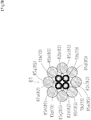
Fig. 8 shows a cross-sectional view of a wire rope according to the fourth embodiment. -
Fig. 9 shows a cross-sectional view of a wire rope according to the fifth embodiment. - Below, the aforementioned embodiments of the present invention will be described with reference to the drawings.
-
Fig. 1 shows a cross-sectional view of the wire rope according to the first embodiment of the present invention.Fig. 2 shows a first hardness distribution of a cross-section of a special metal element wire used for the wire rope according to first embodiment.Fig. 3 shows a second hardness distribution of a cross-section of a special metal element wire used for the wire rope according to first embodiment. - With reference to
Fig. 1 , a wire rope 1 comprises a core wire 3 (which corresponds to the "special metal element wire" according to the present invention) located at the center, and 6 side wires 5 (5a, 5b, 5c, 5d, 5e, and 5f) wound around thecore wire 3. - The
core wire 3 is a metal element wire having a circular cross-section extending from the front end to the base end through the center of the wire rope 1. There is no particular limitation for the material of thecore wire 3, but stainless steel is used in the present embodiment. - Here, the
core wire 3 has a hardness of the peripheral part in a cross-section higher than that of the center in the cross-section. That is, thecore wire 3 is configured to have a structure where only the surface of thecore wire 3 is hardened, but the inside of thecore wire 3 is not hardened. This structure successfully serves not only to maintain the flexibility of thecore wire 3 but also to improve the resistance to abrasion due to contacts with theside wires 5. - Note that conventionally known methods such as swaging and drawing dies can be used in order to obtain a hardness of the peripheral part in a cross-section of the metal element wire higher than that of the center in the cross-section.
- Further, the structure in which only the surface of the
core wire 3 is hardened, but the inside of thecore wire 3 is not hardened may be, for example, a structure in which the hardness of thecore wire 3 increases in the second-order fashion toward the outer periphery from the center in a cross-section of the wire rope 1 as shown inFig. 2 , or may be a structure in which the hardness increases in the linear fashion, or may be a structure in which the hardness of thecore wire 3 shows a flat region in the vicinity of the center of the wire rope 1, and increases toward the outer periphery from the flat region as shown inFig. 3 . - Note that the hardness described in
Figs. 2 and3 is expressed in the Vickers hardness as measured with a Vickers hardness meter, and has a unit of "HV." - The hardness of the
core wire 3 inFig. 2 is about 650 HV at the center in a cross-section of the wire rope 1 while it is about 700 HV at the outer periphery, showing a difference of 50 HV. The hardness of thecore wire 3 inFig. 3 is constant at about 650 HV in the vicinity of the center of the wire rope 1 while it is about 700 HV at the outer periphery, showing a difference of 50 HV. - Note that the experiments performed by the present applicant demonstrated that the flexibility and abrasion resistance was improved even when the hardness at the center in a cross-section was decreased to 550 HV, and the hardness at the outer periphery in the cross-section was decreased to 580 HV.
- In contrast, the flexibility of the wire rope 1 was impaired and the durability decreased when the hardness of the entire region in a cross-section of the wire rope 1 was, for example, 700 HV.
- The side wires 5 (5a, 5b, 5c, 5d, 5e, and 5f), which are metal element wires each having a circular cross-section, are spirally wound around the
core wire 3 in the longitudinal direction. There is no particular limitation for the material of the side wires 5 (5a, 5b, 5c, 5d, 5e, and 5f) as well, but stainless steel is used in the present embodiment. In addition to this, tungsten may also be used. - In the wire rope 1 according to the present embodiment, the
core wire 3 having a hardness of the peripheral part in a cross-section higher than that of the center is arranged at the center of the wire rope 1 such that the multiple wires 5 (5a, 5b, 5c, 5d, 5e, and 5f) all make contacts with thecore wire 3. This can improve the durability of the wire rope. - Below, a second embodiment of the present invention will be described. Descriptions will be omitted for the parts common with the first embodiment, to which the same reference numbers will be assigned in the figures.
Fig. 4 shows a side view of a wire rope according to the second embodiment, andFig. 5 shows a cross-sectional view at A-A inFig. 4 . - With reference to
Figs. 4 and5 , awire rope 11 comprises acore wire 3 located at the center, and 6 side wires 15 (15a, 15b, 15c, 15d, 15e, and 15f) wound around thecore wire 3. - The side wires 15 (15a, 15b, 15c, 15d, 15e, and 15f), which are metal element wires each deforestation-processed into an approximately trapezoidal shape, are spirally wound around the
core wire 3 in the longitudinal direction. There is no particular limitation for the material of the side wires 15 (15a, 15b, 15c, 15d, 15e, and 15f), but stainless steel is used in the present embodiment. In addition to this, tungsten may also be used. - In the
wire rope 11 according to the present embodiment, thecore wire 3 having a hardness of the peripheral part in a cross-section higher than that of the center is arranged at the center of the wire rope 1 such that the 6 side wires 5 (5a, 5b, 5c, 5d, 5e, and 5f) configured to be approximately trapezoidal and each having an approximately trapezoidal cross-section all make surface contacts with thecore wire 3, and thewire rope 11 is configured to have an approximately circular cross-sectional outer periphery. This can improve not only the torque transmissibility of the wire rope 11 (the torque transmissibility to one end of a wire rope when the other end of the wire rope is rotated) but also the durability of the wire rope. - Below, a third embodiment of the present invention will be described. Descriptions will be omitted for the parts common with the first embodiment, to which the same reference numbers will be assigned in the figures.
Fig. 6 shows a side view of a wire rope according to the third embodiment, andFig. 7 shows a cross-sectional view at B-B inFig. 6 . - With reference to
Figs. 6 and7 , awire rope 101 comprises thecore wire rope 11 according to the second embodiment located at the center, and 6side wire ropes core wire rope 11. - The
side wire ropes core wire rope 11, and are spirally wound around thecore wire rope 11 in the longitudinal direction. - That is, the
side wire rope 21 comprises acore wire 3a located at the center (which corresponds to the "special metal element wire" according to the present invention) and 6 side wires 25 (25a, 25b, 25c, 25d, 25e, and 25f) wound around thecore wire 3a, and theside wire rope 31 comprises acore wire 3b (which corresponds to the "special metal element wire" according to the present invention) located at the center and 6 side wires 35 (35a, 35b, 35c, 35d, 35e, and 35f) wound around thecore wire 3b, and theside wire rope 41 comprises a core wire 3c (which corresponds to the "special metal element wire" according to the present invention) located at the center and 6 side wires 45 (45a, 45b, 45c, 45d, 45e, and 45f) wound around the core wire 3c. - Further, the
side wire rope 51 comprises acore wire 3d (which corresponds to the "special metal element wire" according to the present invention) located at the center and 6 side wires 55 (55a, 55b, 55c, 55d, 55e, and 55f) wound around thecore wire 3d, and theside wire rope 61 comprises acore wire 3e (which corresponds to the "special metal element wire" according to the present invention) located at the center and 6 side wires 65 (65a, 65b, 65c, 65d, 65e, and 65f) wound around thecore wire 3e, and theside wire rope 71 comprises a core wire of 3f (which corresponds to the "special metal element wire" according to the present invention) located at the center and 6 side wires 75 (75a, 75b, 75c, 75d, 75e, and 75f) wound around thecore wire 3f. - The
wire rope 101 according to the present embodiment is formed by twisting a plurality of wire ropes in each of which a core wire having a hardness of the peripheral part in a cross-section higher than that of the center is arranged at the center such that 6 side wires each having an approximately trapezoidal cross-section all make contacts with the core wire, each wire rope being configured to have an approximately circular cross-sectional outer periphery. This can further improve not only the torque transmissibility of the wire rope 101 (the torque transmissibility to one end of a wire rope when the other end of the wire rope is rotated) but also the durability of the wire rope. - Below, a fourth embodiment will be described.
Fig. 8 shows a cross-sectional view of a wire rope according to the fourth embodiment. - With reference to
Fig. 8 , awire rope 81 comprises a core twistedwire 13 located at the center, 4side wires 82 arranged at the outside of the core twistedwire 13, and 8side wires 85 wound around the core twistedwire 13 and theside wires 82. - The core twisted
wire 13 comprises 4 metal element wires (13a, 13b, 13c, and 13d (each corresponds to the "special metal element wire" according to the present invention)), and each metal element wire has a circular cross-section. There is no particular limitation for the material of the metal element wires (13a, 13b, 13c, and 13d), but stainless steel is used in the present embodiment. - Here, the metal element wires (13a, 13b, 13c, and 13d), which constitutes the core twisted
wire 13, each have a hardness of the peripheral part in a cross-section higher than that of the central part in the cross-section. That is, each metal element wire (13a, 13b, 13c, and 13d) has a structure in which only the surface of the metal element wire is hardened, but the inside of the metal element wire is not hardened. Further, the core twistedwire 13 is formed by twisting four of this metal element wire. This can improve the flexibility of the core twistedwire 13, and can improve the durability. - Moreover, 4 side wires 82 (82a, 82b, 82c, and 82d), each of which has a circular cross-section, and comprises metal element wires each having a diameter smaller than that of each metal element wire (13a, 13b, 13c, and 13d) of the core twisted
wire 13, is arranged at the outside of the core twistedwire 13. Note that there is no particular limitation for the material of the side wires 82 (82a, 82b, 82c, and 82d), but stainless steel is used in the present embodiment. - Further, 8 side wires 85 (85a, 85b, 85c, 85d, 85e, 85f, 85g, and 85h), which are metal element wires each having a circular cross-section, are arranged at the outside of the core twisted
wire 13 and the side wires 82 (82a, 82b, 82c, and 82d). Note that there is no particular limitation for the material of the side wires 85 (85a, 85b, 85c, 85d, 85e, 85f, 85g, and 85h), but stainless steel is used in the present embodiment. - In the
wire rope 81 according to the present embodiment, the core twistedwire 13 formed by twisting 4 metal element wires each having a hardness of the peripheral part in a cross-section higher than that of the central part is arranged at the center. This can further improve the flexibility of thewire rope 81, and can improve the durability. - Below, a fifth embodiment will be described.
Fig. 9 shows a cross-sectional view of a wire rope according to the fifth embodiment. - With reference to
Fig. 9 , awire rope 91 comprises a core twistedwire 23 located at the center, 4side wires 92 arranged at the outside of the core twistedwire 23, and 8side wires 95 wound around the core twistedwire 23 and theside wires 92. - The core twisted
wire 23 comprises 4 metal element wires (23a, 23b, 23c, and 23d (each corresponds to the "special metal element wire" according to the present invention)), and each of the metal element wire has a circular cross-section. There is no particular limitation for the material of the metal element wires (23a, 23b, 23c, and 23d), but stainless steel is used in the present embodiment. - Here, among the metal element wires (23a, 23b, 23c, and 23d) of the core twisted
wire 23, themetal element wire 23d has a hardness of the peripheral part in a cross-section higher than that of the center in the cross-section. That is, themetal element wire 23d is configured to have a structure in which only the surface of the metal element wire is hardened, but the inside of the metal element wire is not hardened. On the other hand, themetal element wires - Further, the core twisted
wire 23 is formed by twisting the 4 metal element wires. This can further improve the flexibility of the core twistedwire 23. - Moreover, 4 side wires 92 (92a, 92b, 92c, and 92d), each of which has a circular cross-section, and comprises metal element wires each having a diameter smaller than that of each metal element wires (23a, 23b, 23c, and 23d) of the core twisted
wire 23, is arranged at the outside of the core twistedwire 23. Note that there is no particular limitation for the material of the side wires 92 (92a, 92b, 92c, and 92d), but stainless steel is used in the present embodiment. - Furthermore, 8 side wires 95 (95a, 95b, 95c, 95d, 95e, 95f, 95g, and 95h), which are metal element wires each having a circular cross-section, are arranged at the outside of the core twisted
wire 23 and the side wire 92 (92a, 92b, 92c, and 92d). Note that there is no particular limitation for the material of the side wires 95 (95a, 95b, 95c, 95d, 95e, 95f, 95g, and 95h), but stainless steel is used in the present embodiment. - In the
wire rope 91 according to the present embodiment, the core twistedwire 23 formed with the metal element wires each having a hardness of the peripheral part in a cross-section higher than that of the central part is arranged at the center of thewire rope 91. This can improve the flexibility and durability of thewire rope 91. - Although the wire ropes according to the various embodiments of the present invention are described above, the present invention shall not be limited to these embodiments. The present invention can be practiced with various modifications made without departing from the scope of the present invention.
- For example, in the first embodiment to the third embodiment, the
side wires - Moreover, in the fourth and fifth embodiments, the core twisted
wires - Moreover, in the fourth and fifth embodiments, the
side wires wire - Moreover, in the fourth and fifth embodiments, the
side wires side wires -
- 1, 11, 21, 31, 41, 51, 61, 71, 81, 91, 101
- Wire rope
- 3 Core
- wire
- 13, 23
- Twisted wire
- 5, 15, 25, 35, 45, 55, 65, 75, 82, 85, 92, 95
- Side wire
Claims (6)
- A wire rope formed by winding multiple metal element wires,
wherein at least one special metal element wire among the multiple metal element wires has a hardness of the outer periphery in a cross-section higher than that of the center in the cross-section. - The wire rope according to claim 1, wherein the at least one special metal element wire is arranged at the center.
- The wire rope according to claim 2, wherein the multiple metal element wires consist only of the at least one special metal element wire and multiple side metal element wires making contacts with the at least one special metal element wire.
- The wire rope according to claim 3, wherein the at least one special metal element wire has a circular cross-section, and the multiple side metal element wires each have an approximately trapezoidal cross-section.
- A wire rope formed by twisting a plurality of wire ropes according to claim 4.
- The wire rope according to claim 1, wherein the at least one special metal element wire comprises multiple special metal element wires, and a twisted wire in which the multiple special metal element wires are twisted is arranged at the center.
Applications Claiming Priority (1)
| Application Number | Priority Date | Filing Date | Title |
|---|---|---|---|
| PCT/JP2016/063945 WO2017195284A1 (en) | 2016-05-11 | 2016-05-11 | Wire rope |
Publications (2)
| Publication Number | Publication Date |
|---|---|
| EP3456876A1 true EP3456876A1 (en) | 2019-03-20 |
| EP3456876A4 EP3456876A4 (en) | 2019-11-20 |
Family
ID=60266520
Family Applications (1)
| Application Number | Title | Priority Date | Filing Date |
|---|---|---|---|
| EP16829223.3A Withdrawn EP3456876A4 (en) | 2016-05-11 | 2016-05-11 | Wire rope |
Country Status (6)
| Country | Link |
|---|---|
| US (1) | US20170328000A1 (en) |
| EP (1) | EP3456876A4 (en) |
| JP (1) | JP6344781B2 (en) |
| KR (1) | KR102001319B1 (en) |
| CN (1) | CN107923124A (en) |
| WO (1) | WO2017195284A1 (en) |
Families Citing this family (5)
| Publication number | Priority date | Publication date | Assignee | Title |
|---|---|---|---|---|
| CN108431313B (en) * | 2015-12-21 | 2021-04-27 | 日本板硝子株式会社 | Cords for rubber reinforcement and rubber products using the same |
| JP7304160B2 (en) * | 2018-01-26 | 2023-07-06 | 東京製綱株式会社 | Flexible weight wire rope |
| ES2960882T3 (en) * | 2018-10-23 | 2024-03-07 | Bekaert Advanced Cords Aalter Nv | Steel wire rope and method of producing it |
| CN110538945B (en) * | 2019-09-19 | 2021-04-13 | 中国人民解放军陆军装甲兵学院 | Refractory high-entropy alloy stranded wire material, application and preparation method thereof |
| JP7846513B2 (en) | 2021-10-27 | 2026-04-15 | 朝日インテック株式会社 | wire rope |
Family Cites Families (36)
| Publication number | Priority date | Publication date | Assignee | Title |
|---|---|---|---|---|
| JPS57195948A (en) * | 1981-05-29 | 1982-12-01 | Koichi Hamada | Wire rope |
| JPS6241387A (en) * | 1985-08-15 | 1987-02-23 | 住友電気工業株式会社 | Steel stranded wire for PC |
| DE3632298A1 (en) * | 1986-09-23 | 1988-04-07 | Saar Gmbh Drahtseilwerk | WIRE ROPE FOR A HANGING INSERT OVER A LARGE HEIGHT DIFFERENCE, IN PARTICULAR CONVEYOR BASKET ROPE, DEEP ROPE ROPE OR ROPEWAY ROPE |
| JPH0474840A (en) * | 1990-07-18 | 1992-03-10 | Tokyo Tungsten Co Ltd | Printed wire and its manufacturing method |
| JP3108231B2 (en) * | 1992-12-18 | 2000-11-13 | 株式会社ブリヂストン | Steel cord |
| JP3191839B2 (en) * | 1993-06-14 | 2001-07-23 | 住友電気工業株式会社 | Inner wire for control cable and method of manufacturing the same |
| JPH08144182A (en) | 1994-11-15 | 1996-06-04 | Toyota Autom Loom Works Ltd | Stranded wire rope and device for shedding in loom |
| JP2772627B2 (en) * | 1995-05-16 | 1998-07-02 | 東京製綱株式会社 | Ultra-high strength steel wire and steel cord for rubber reinforcement |
| JP3096238B2 (en) * | 1996-02-15 | 2000-10-10 | 神鋼鋼線工業株式会社 | Wire rope |
| US6399886B1 (en) * | 1997-05-02 | 2002-06-04 | General Science & Technology Corp. | Multifilament drawn radiopaque high elastic cables and methods of making the same |
| JPH11309509A (en) * | 1998-04-24 | 1999-11-09 | Nippon Steel Corp | High-strength ultrafine steel wire with excellent twisting characteristics and method for producing the same |
| ES2195528T3 (en) * | 1998-07-30 | 2003-12-01 | Aster | THREAD OF COMPOSITE MATERIAL THAT INCLUDES A SOUL OF CARBON STEEL AND AN EXTERNAL LAYER OF STAINLESS STEEL. |
| JP2000096151A (en) * | 1998-09-21 | 2000-04-04 | Nippon Koshuha Steel Co Ltd | Production of wire rod or bar stock made of metal for cold shear cutting |
| JP3001572B1 (en) * | 1999-03-04 | 2000-01-24 | 新日本製鐵株式会社 | High-strength, high-ductility ultrafine steel wire, stranded wire, and method for producing the same |
| US6339920B1 (en) * | 1999-08-27 | 2002-01-22 | Kawasaki Steel Corporation | Rotation-resisting wire rope |
| AU1765801A (en) * | 1999-11-16 | 2001-05-30 | Utilx Corporation | Wire rope lubrication |
| US6327841B1 (en) * | 1999-11-16 | 2001-12-11 | Utilx Corporation | Wire rope lubrication |
| JP2002113541A (en) * | 2000-10-10 | 2002-04-16 | Ykk Corp | Metal wire, and manufacturing method thereof |
| US7104299B2 (en) * | 2001-04-23 | 2006-09-12 | The Goodyear Tire & Rubber Company | Two piece tire with improved tire tread belt |
| KR100426059B1 (en) * | 2001-12-26 | 2004-04-06 | 홍덕스틸코드주식회사 | Saw wire making superior slicing surfaces |
| JP2004124342A (en) | 2002-10-04 | 2004-04-22 | Shuji Tarumoto | Inner wire rope |
| JP2004327254A (en) | 2003-04-24 | 2004-11-18 | Fujikura Ltd | High corrosion resistant steel core aluminum stranded wire |
| US7093416B2 (en) * | 2004-06-17 | 2006-08-22 | 3M Innovative Properties Company | Cable and method of making the same |
| JP4804860B2 (en) * | 2004-10-27 | 2011-11-02 | 古河電気工業株式会社 | Composite twisted conductor |
| US7458200B2 (en) * | 2005-12-08 | 2008-12-02 | The Goodyear Tire & Rubber Co. | High elongation cable |
| CN101016701B (en) * | 2007-02-15 | 2012-01-11 | 孟凡英 | Abrasion and cutting proof rope |
| CN201351246Y (en) * | 2009-01-21 | 2009-11-25 | 江苏宏泰不锈钢丝绳有限公司 | Magnetic-free corrosion-resistant stainless steel wire rope |
| MX382704B (en) * | 2010-04-30 | 2025-03-13 | Schlumberger Tech B V Star | COMPONENTS OF PETROLEUM FIELDS AND METHODS OF MANUFACTURING AND USING THEM. |
| EP2585632A4 (en) * | 2010-07-23 | 2015-04-15 | Schlumberger Technology Bv | CABLE HAVING A REINFORCING ELEMENT WITH BONDED POLYMER COATINGS TO CREATE A CONTINUOUSLY BONDED REINFORCED REINFORCING ELEMENT SYSTEM |
| EP2436808A1 (en) * | 2010-09-30 | 2012-04-04 | NV Bekaert SA | Multi-filament with annealed copper core and drawn steel layer |
| FR2991632B1 (en) * | 2012-06-07 | 2014-06-27 | Michelin & Cie | HYBRID ROD LIFT FOR PNEUMATIC. |
| DE102012112911A1 (en) * | 2012-12-21 | 2014-06-26 | Casar Drahtseilwerk Saar Gmbh | Wire rope and method and apparatus for making the wire rope |
| JP2014169507A (en) * | 2013-03-01 | 2014-09-18 | Bridgestone Corp | Steel wire for reinforcing rubber article and rubber article including the same |
| US9428858B2 (en) * | 2013-03-15 | 2016-08-30 | 1735729 Alberta Ltd. | Wire rope and method of constructing wire rope |
| RU2543400C1 (en) * | 2013-08-08 | 2015-02-27 | Общество С Ограниченной Ответственностью "Армастил" | Cable and method of its production |
| JP2015137428A (en) * | 2014-01-20 | 2015-07-30 | 朝日インテック株式会社 | Twisted wire and guide wire using the twisted wire |
-
2016
- 2016-05-11 JP JP2016563867A patent/JP6344781B2/en not_active Ceased
- 2016-05-11 KR KR1020177000910A patent/KR102001319B1/en active Active
- 2016-05-11 CN CN201680001589.4A patent/CN107923124A/en active Pending
- 2016-05-11 WO PCT/JP2016/063945 patent/WO2017195284A1/en not_active Ceased
- 2016-05-11 EP EP16829223.3A patent/EP3456876A4/en not_active Withdrawn
-
2017
- 2017-03-06 US US15/450,446 patent/US20170328000A1/en not_active Abandoned
Also Published As
| Publication number | Publication date |
|---|---|
| JP6344781B2 (en) | 2018-06-20 |
| JPWO2017195284A1 (en) | 2018-06-07 |
| KR102001319B1 (en) | 2019-07-17 |
| KR20170141181A (en) | 2017-12-22 |
| US20170328000A1 (en) | 2017-11-16 |
| EP3456876A4 (en) | 2019-11-20 |
| CN107923124A (en) | 2018-04-17 |
| WO2017195284A1 (en) | 2017-11-16 |
Similar Documents
| Publication | Publication Date | Title |
|---|---|---|
| KR102001319B1 (en) | Wire rope | |
| EP2407592A2 (en) | Elevator wire rope | |
| ES2960882T3 (en) | Steel wire rope and method of producing it | |
| JP6631979B2 (en) | Wire rope | |
| JP6329695B1 (en) | Multilayer body, multilayer hollow body, and catheter provided with multilayer hollow body | |
| JP2010508450A (en) | Multi strand steel wire rope | |
| US20220170204A1 (en) | Wire rope | |
| JP4153471B2 (en) | Rope for operation | |
| JP2015196937A (en) | Steel cord for rubber article reinforcement | |
| RU186969U1 (en) | STEEL ROPE WITH POLYMERIC COATING | |
| JP5970612B2 (en) | Insulated wire, manufacturing method thereof, and wire harness | |
| JP6176792B2 (en) | Wire rope | |
| CN208857576U (en) | The automotive window lifting stainless steel wirerope of (1+6+6/6) structure | |
| KR102677692B1 (en) | A coil spring | |
| KR100409105B1 (en) | Self-anointing type wire rope with improved wear-resistance, and manufacturing method thereof | |
| JPS609987A (en) | Wire rope and production thereof | |
| JP4868804B2 (en) | Steel cord for tire reinforcement | |
| JP6093549B2 (en) | Stainless steel wire for operation | |
| JP6851014B2 (en) | Wire rope | |
| JPH0673673A (en) | Steel cord for reinforcing rubber | |
| JP2017040335A (en) | Control cable | |
| KR200435622Y1 (en) | Mattress structures | |
| JPS5976986A (en) | Core rope of wire rope | |
| JPH05279973A (en) | Multilayer twisted steel cord for rubber elastomer | |
| KR20010109546A (en) | Wire cable having strand core coated with synthetic resins for machine operating |
Legal Events
| Date | Code | Title | Description |
|---|---|---|---|
| STAA | Information on the status of an ep patent application or granted ep patent |
Free format text: STATUS: UNKNOWN |
|
| STAA | Information on the status of an ep patent application or granted ep patent |
Free format text: STATUS: THE INTERNATIONAL PUBLICATION HAS BEEN MADE |
|
| PUAI | Public reference made under article 153(3) epc to a published international application that has entered the european phase |
Free format text: ORIGINAL CODE: 0009012 |
|
| STAA | Information on the status of an ep patent application or granted ep patent |
Free format text: STATUS: REQUEST FOR EXAMINATION WAS MADE |
|
| 17P | Request for examination filed |
Effective date: 20170201 |
|
| AK | Designated contracting states |
Kind code of ref document: A1 Designated state(s): AL AT BE BG CH CY CZ DE DK EE ES FI FR GB GR HR HU IE IS IT LI LT LU LV MC MK MT NL NO PL PT RO RS SE SI SK SM TR |
|
| AX | Request for extension of the european patent |
Extension state: BA ME |
|
| DAV | Request for validation of the european patent (deleted) | ||
| DAX | Request for extension of the european patent (deleted) | ||
| R17P | Request for examination filed (corrected) |
Effective date: 20170201 |
|
| A4 | Supplementary search report drawn up and despatched |
Effective date: 20191023 |
|
| RIC1 | Information provided on ipc code assigned before grant |
Ipc: D07B 1/06 20060101AFI20191017BHEP |
|
| STAA | Information on the status of an ep patent application or granted ep patent |
Free format text: STATUS: THE APPLICATION IS DEEMED TO BE WITHDRAWN |
|
| 18D | Application deemed to be withdrawn |
Effective date: 20200603 |