EP3456872A1 - Washing and/or drying machine - Google Patents
Washing and/or drying machine Download PDFInfo
- Publication number
- EP3456872A1 EP3456872A1 EP17191873.3A EP17191873A EP3456872A1 EP 3456872 A1 EP3456872 A1 EP 3456872A1 EP 17191873 A EP17191873 A EP 17191873A EP 3456872 A1 EP3456872 A1 EP 3456872A1
- Authority
- EP
- European Patent Office
- Prior art keywords
- washing
- magnet
- movable element
- drum
- drying machine
- Prior art date
- Legal status (The legal status is an assumption and is not a legal conclusion. Google has not performed a legal analysis and makes no representation as to the accuracy of the status listed.)
- Withdrawn
Links
Images


Classifications
-
- D—TEXTILES; PAPER
- D06—TREATMENT OF TEXTILES OR THE LIKE; LAUNDERING; FLEXIBLE MATERIALS NOT OTHERWISE PROVIDED FOR
- D06F—LAUNDERING, DRYING, IRONING, PRESSING OR FOLDING TEXTILE ARTICLES
- D06F37/00—Details specific to washing machines covered by groups D06F21/00 - D06F25/00
- D06F37/02—Rotary receptacles, e.g. drums
- D06F37/04—Rotary receptacles, e.g. drums adapted for rotation or oscillation about a horizontal or inclined axis
- D06F37/06—Ribs, lifters, or rubbing means forming part of the receptacle
-
- D—TEXTILES; PAPER
- D06—TREATMENT OF TEXTILES OR THE LIKE; LAUNDERING; FLEXIBLE MATERIALS NOT OTHERWISE PROVIDED FOR
- D06F—LAUNDERING, DRYING, IRONING, PRESSING OR FOLDING TEXTILE ARTICLES
- D06F37/00—Details specific to washing machines covered by groups D06F21/00 - D06F25/00
- D06F37/02—Rotary receptacles, e.g. drums
- D06F37/12—Rotary receptacles, e.g. drums adapted for rotation or oscillation about a vertical axis
- D06F37/14—Ribs or rubbing means forming part of the receptacle
Definitions
- the present disclosure relates to a washing and/or drying machine.
- Washing machines are used for washing washable items, including garments such as clothes. Typically a user can select a suitable washing cycle via an interface on a front face of the washing machine.
- the interface usually includes a number of control knobs and/or buttons.
- a drying machine also known as a tumble dryer, is operable to dry items such as garments placed therein. Some washing machines have both washing and drying functionality.
- a washing and/or drying machine comprising: a main body portion; a drum arranged for rotation within the main body portion; at least one movable element located on an inside surface of the drum, the at least one movable element comprising a first magnet; and wherein the at least one movable element is configured and arranged for movement between a non-extended position and an extended position for separating one or more items of a washing load from the inside surface of the drum, the movement of the movable element being in response to the first magnet of the movable element being positioned within a magnetic field of a second magnet, the second magnet being positioned in the machine adjacent to the drum.
- the at least one movable element comprises a magnetic material, the movable element being the first magnet.
- the at least one movable element comprises a non-magnetic material, the first magnet being operatively connected to the at least one movable element.
- the first magnet comprises a permanent magnet and the second magnet comprises an electromagnet.
- the washing machine comprises a controller communicatively connected to one or more sensors in the machine, the controller arranged to control a current applied to the electromagnet.
- the controller is arranged to control a magnitude of the current applied to the electromagnet, in response to information of the washing load obtained from the one or more sensors in the machine.
- the information received from the one or more sensors comprises information of whether one or more items of the washing load are stuck to the inside surface of the drum.
- the information received from the one or more sensors comprises a weight of the washing load.
- the machine comprises a biasing element arranged to return the at least one movable element to the non-extended position when the first magnet is not subject to the magnetic field of the second magnet.
- the biasing element comprises a rubber band.
- the second magnet is positioned adjacent to a highest point of the drum.
- the at least one movable element comprises a paddle or lifter of the washing machine.
- the machine comprises a combined washing and drying machine.
- the machine is configured to actuate the movable element in a time period between a spin cycle and a drying cycle.
- the present disclosure has applicability to clothes washing and/or drying machines.
- a washable item such as a garment or garments in a washing machine
- the user has to select a washing cycle from a variety of available washing cycles.
- a hot washing cycle possibly with additional rinse and soak stages.
- Each selectable washing cycle typically has one or more fixed parameters, such as duration and temperature.
- Some washing machines also have a tumble drying function, and such machines are sometimes referred to as washer-dryers or combined washing and drying machines.
- the final stage of a washing cycle, before a drying cycle is begun, is often a spin cycle where a drum of the washing machine is rotated at high speed to remove excess water from garments in the washing machine. This rotation can be clockwise or anti-clockwise, or cycle between clockwise and anticlockwise spin cycles.
- the centrifugal force of the spin cycle pushes the garment(s) on to an inside surface of the drum. At least some of these garments may accordingly become stuck to the drum. The moisture on these stuck garments may not easily be removed during the spin cycle. Furthermore, these garments may remain stuck during a subsequent drying cycle and thus prevent air circulation between the garments, which may reduce the effectiveness of the drying cycle. Stuck garments may also cause these same problems in tumble dryers. In a tumble dryer a user can typically select duration of a drying cycle, and in some examples a user can also select heating intensity of a drying cycle.
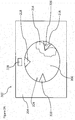
- FIG. 1 schematically shows a washing machine 102 according to an example.
- the washing machine 102 comprises a main body portion 104 and a drum 106 which is arranged to hold one or more garments or items of a washing load to be washed. Washing detergent and/or fabric softener may also be placed directly in to the drum 106. Alternatively washing detergent and/or fabric softener may be placed in to a tray or holder 112 arranged for this purpose.
- a user interface 108 is provided which enables a user to select one or more washing parameters and/or settings.
- a display 110 is also provided which outputs information to a user of the washing machine. For example information displayed on the display 110 may be information regarding options selected via user interface 108, information regarding a washing cycle in progress such as time remaining etc.
- the washing machine 102 also comprises a controller 130 shown schematically at 130.
- the controller 130 comprises a memory and a processor.
- the controller 130 is arranged for controlling operations of the washing machine 102.
- the washing machine 102 also comprises a suitable power connection enabling the washing machine 102 to be connected to an electricity supply such as mains electricity, as well as a suitable inlet and outlet for water.
- FIGS 2A to 2C show schematically some portions of a washing machine 202 according to an example.
- the washing machine 202 comprises a drum 206 arranged for rotation in the main body portion 204 of the washing machine 202.
- the drum 206 may be a metal or a non-metal. Where the drum 206 is made of metal, it may comprise steel or stainless steel. Where a steel drum is used, the drum may also have an enamel coating. Where the drum is a non-metal, the drum may be formed of a polymer plastic. In an example the drum is non-magnetic, or coated with a non-magnetic material.
- the drum 206 comprises one or more movable elements which can move relative to the drum 206.
- movable elements 216, 218 and 220 there are three movable elements 216, 218 and 220. It will be understood that in other examples more or fewer movable elements may be provided. These movable elements 216, 218 and 220 may be in the form of machine drum paddles or "lifters". In conventional washing machines such paddles are fixed to the drum 206 so that they do not move relative to the drum. A purpose of the movable elements is to try and prevent items that are being washed from becoming stuck to an inside surface 224 of the drum 206, by lifting garments away from the inside surface 224.
- movable elements 218 and 220 may operate in the same fashion.
- the drum may comprise a mixture of one or more movable elements as described herein and one or more conventional paddles or lifters.
- the drum 206 is rotating, for example during a spin cycle at the end of a washing cycle.
- the item 214 is also at least partially stuck to the inside surface 224 of the drum 206, due to the centrifugal force as the drum rotates.
- the movable element is constructed and arranged to move inwardly of the drum inner surface 216 so as to release or separate the item 214 from the drum inner surface 224, by pushing the item 214 inwardly of the drum 206.
- the movement of the movable element 216 is effected by a pair of magnets.
- the movable element 216 comprises a first magnet 226, and the washing machine comprises a second magnet 228 outside of the drum 206.
- the movable element 216 may itself be made of a magnetic material. That is in some examples the movable element 216 may comprise the first magnet 226. Additionally or alternatively the movable element 216 is attached to first magnet 226.
- the material of the movable element 216 is non-magnetic (e.g. a polymer plastic), the movable element 216 being attached to first magnet 226.
- the first magnet 226 is a permanent magnet.
- the movable element may be considered to be in a non-extended position. Although these Figures show a single "second" magnet 228, it will be understood that in other examples two or more of such magnets may be arranged adjacent to the drum 206.
- the second magnet 228 is positioned adjacent the highest point of the drum 206.
- the second magnet 228 comprises an electromagnet.
- the second magnet 228 comprises a permanent magnet.
- the drum has rotated such that the movable element 216 is adjacent or substantially adjacent the second magnet.
- the first and second magnets are arranged such that they act to repel each other.
- the magnet 226 is within the magnetic field range of magnet 228, which causes the movable element 216 to be moved away from the second magnet 228.
- the movable element 216 has been pushed a distance x away from the inside surface 224 of the drum 206.
- the movable element 216 may be considered to be in an extended position. This movement has pushed item 214 off the inner surface 224 of the drum.
- the item 214 is falling downwardly in the drum under gravity, as shown schematically by arrow 232.
- this may maximise the chance of dislodging a stuck item being washed from the inside surface 224 of the drum 206, since the movable element 216 works with the force of gravity.
- the movable element 216 is biased towards the inside surface 224 of the drum 206 by a biasing element schematically shown at 234.
- the biasing element has a resilience which can be overcome by the force of the first magnet 226 and the second magnet 228 repelling each other.
- the resilience of the biasing element 234 draws the movable element 216 back towards the inside surface 224 of the drum.
- Figures 3A and 3B show the first and second magnets repelling each other, by arranging the magnets 226 and 228 so that opposing poles face each other, when the magnets 226 and 228 are adjacent to each other. This may be achieved as shown in Figure 3A where the magnets are arranged so that south poles of the magnets face each other, or as shown in Figure 3B where north poles face each other.
- the first magnet 226 and the second magnet 228 may both be permanent magnets.
- one of the first magnet 226 and second magnet 228 may be a ferromagnet or a permanent magnet, with the other of the first magnet 226 and second magnet 228 being an electromagnet.
- the first magnet 226 is a permanent magnet
- the second magnet 228 is an electromagnet.
- the second magnet 228 is only energised at certain times.
- the second magnet 228 may only be energised at a time when it is deemed necessary to separate items from the inside surface of the drum.
- the second magnet 228 may only be energised during a latter part of a spin cycle.
- the second magnet 228 is energised only during a specific separation phase in which the drum 206 is driven relatively slowly and the movable element 216 is driven to separate the items from the drum, when the movable element 216 is adjacent to the second magnet 228. In some examples this is conducted prior to a planned or anticipated drying cycle.
- the operation of the movable element may also take place during the drying cycle itself.
- operation of the electromagnet may be cycled, so that during a separation phase (i.e. separation of items or garments from the drum inside surface), then the second magnet 228 is energised only when the first magnet 226 is proximate to or adjacent to the second magnet 228.
- the electromagnet is energised by the controller of the washing machine causing an electrical current to be applied to the electromagnet.
- Figure 4 shows a controller 430.
- the controller comprises a memory 450 and a processor 452.
- the controller 430 is communicatively connected to an electromagnet 428 (the "second magnet").
- the controller 430 is also communicatively connected to at least one sensor 440.
- the controller 430 can control when and in what manner the electromagnet 428 is energised.
- the strength of the magnetic field caused by the electromagnet 428 may be controlled by the controller based upon one or more sensed aspects of the washing load.
- the electromagnet 428 For example if it is determined that there are no items stuck to the drum, then it may be determined that it is unnecessary to energise the electromagnet 428. If it is determined that there is only a light load in the washing machine, then it may be determined that the movable element 216 in the drum only needs to be moved a relatively small amount or with a relatively low force in order to unstick items. Accordingly a relatively small current may be applied to the electromagnet 428. On the other hand if it is determined that there is a relatively heavy load in the washing machine, then it may be determined that the movable element 216 in the drum needs to be moved a relatively large amount or with a relatively large force in order to unstick items. Accordingly a relatively large current may be applied to the electromagnet 428.
- the at least one sensor 440 may comprise one or more of or any combination of: a weight sensor; an optical sensor; a camera.
- the weight sensor can measure a weight of the load in the washing machine.
- the optical sensor and/or camera can detect a positon of the load in the drum e.g. whether or not items are stuck to the side of the drum.
- the camera and/or optical sensor may also be capable of detecting aspects such as fabrics of the washing load. In some examples a user may be able to manually input the above described information regarding the washing load.
- Figure 5 shows in more detail an arrangement of the at least one movable element, according to an example.
- the at least one movable element is shown at 516, in a non-extended position.
- An inside surface of the washing machine drum 506 is schematically shown at 524.
- the "first" magnet 526 comprises a ferromagnetic/permanent magnet material, for example a metal comprising iron.
- the first magnet 526 comprises a rod or tube attached to the movable element 516.
- a biasing element is shown at 534 and 534'.
- the biasing element 534, 534' may be formed from a single piece of material, or from two or more pieces of material.
- the biasing element 534, 534' is attached to the drum 506.
- the biasing element 534, 534' is attached to the drum 506 at anchor points 550 and 552.
- the biasing element 534, 534' comprises a rubber material, such as a rubber band.
- the biasing element 534, 534' is attached to first magnet 526.
- the biasing element 534, 534' is attached directly to movable element 516. This arrangement works as explained above with respect to Figures 2A to 2C . That is, when the first magnet 526 is subject to a magnetic field of the second magnet 528, then the first magnet 526 is caused to move in the direction of arrow A against the biasing force of the biasing element 534, 534'.
- Direction A may be perpendicular to a tangent of the drum, towards a centre point of the drum. This causes a corresponding movement of movable element 526 in direction A.
- the first magnet 526 moves away from the second magnet 528 as the drum 506 rotates, the first magnet 526 is no longer subject to the magnetic field of second magnet 528. Accordingly, the movable element 516 is drawn back towards the drum surface 524 in the direction of arrow B, under the force of biasing element 534, 534'.
- the surface of the drum 524 is schematically shown as being generally flat, it will be understood that in embodiments the inner surface of the drum will be curved.
- FIG. 6 shows an example process, according to an example.
- the process is started.
- a determination is made as to whether a spin cycle of the washing machine has been completed. If the answer is no, then the process returns to S1. If on the other hand the answer is yes, then the drum is rotated (if necessary) so as to position the movable element in the drum opposite or adjacent to the second magnet in the washing machine. In some examples this involves rotating the drum so that the movable element is at its highest point.
- a determination is made as to whether an item or items in the washing load are stuck to an inside surface of the drum. This determination may be carried out, as described above, by use of one or more sensors.
- the movable element is actuated, as shown at S6. If the determination at S4 is no, then the process may be ended without the movable element needing to be actuated. In some examples the process can then be repeated. For example, S5 and/or S6 may loop back to S3.
- washing machines i.e. a tumble dryer
- washer-dryers combined washing and drying machines
- Washing machines, drying machines or combined washing and drying machines as described herein may have one or more advantages.
- the use of magnets for effecting movement of the one or more movable elements, and in particular where one of the magnets is an electromagnet, enables a variable force to be provided to the one or more movable elements, dependent upon conditions such as fabric type or weight of the washing load.
- the magnets may have a longer lifetime and be less susceptible to corrosion than a spring based arrangement.
- processor or processing system or circuitry referred to herein may in practice be provided by a single chip or integrated circuit or plural chips or integrated circuits, optionally provided as a chipset, an application-specific integrated circuit (ASIC), field-programmable gate array (FPGA), digital signal processor (DSP), graphics processing units (GPUs), etc.
- the chip or chips may comprise circuitry (as well as possibly firmware) for embodying at least one or more of a data processor or processors, a digital signal processor or processors, baseband circuitry and radio frequency circuitry, which are configurable so as to operate in accordance with the exemplary embodiments.
- the exemplary embodiments may be implemented at least in part by computer software stored in (non-transitory) memory and executable by the processor, or by hardware, or by a combination of tangibly stored software and hardware (and tangibly stored firmware).
- the invention also extends to computer programs, particularly computer programs on or in a carrier, adapted for putting the invention into practice.
- the program may be in the form of non-transitory source code, object code, a code intermediate source and object code such as in partially compiled form, or in any other non-transitory form suitable for use in the implementation of processes according to the invention.
- the carrier may be any entity or device capable of carrying the program.
- the carrier may comprise a storage medium, such as a solid-state drive (SSD) or other semiconductor-based RAM; a ROM, for example a CD ROM or a semiconductor ROM; a magnetic recording medium, for example a floppy disk or hard disk; optical memory devices in general; etc.
- SSD solid-state drive
- ROM read-only memory
- magnetic recording medium for example a floppy disk or hard disk
- optical memory devices in general etc.
Abstract
Description
- The present disclosure relates to a washing and/or drying machine.
- Washing machines are used for washing washable items, including garments such as clothes. Typically a user can select a suitable washing cycle via an interface on a front face of the washing machine. The interface usually includes a number of control knobs and/or buttons. A drying machine, also known as a tumble dryer, is operable to dry items such as garments placed therein. Some washing machines have both washing and drying functionality.
- According to a first aspect disclosed herein, there is provided a washing and/or drying machine comprising: a main body portion; a drum arranged for rotation within the main body portion; at least one movable element located on an inside surface of the drum, the at least one movable element comprising a first magnet; and wherein the at least one movable element is configured and arranged for movement between a non-extended position and an extended position for separating one or more items of a washing load from the inside surface of the drum, the movement of the movable element being in response to the first magnet of the movable element being positioned within a magnetic field of a second magnet, the second magnet being positioned in the machine adjacent to the drum.
- According to an example, the at least one movable element comprises a magnetic material, the movable element being the first magnet.
- According to an example, the at least one movable element comprises a non-magnetic material, the first magnet being operatively connected to the at least one movable element.
- According to an example, the first magnet comprises a permanent magnet and the second magnet comprises an electromagnet.
- According to an example, the washing machine comprises a controller communicatively connected to one or more sensors in the machine, the controller arranged to control a current applied to the electromagnet.
- According to an example, the controller is arranged to control a magnitude of the current applied to the electromagnet, in response to information of the washing load obtained from the one or more sensors in the machine.
- According to an example, the information received from the one or more sensors comprises information of whether one or more items of the washing load are stuck to the inside surface of the drum.
- According to an example, the information received from the one or more sensors comprises a weight of the washing load.
- According to an example, the machine comprises a biasing element arranged to return the at least one movable element to the non-extended position when the first magnet is not subject to the magnetic field of the second magnet.
- According to an example, the biasing element comprises a rubber band.
- According to an example the second magnet is positioned adjacent to a highest point of the drum.
- According to an example the at least one movable element comprises a paddle or lifter of the washing machine.
- According to an example the machine comprises a combined washing and drying machine.
- According to an example the machine is configured to actuate the movable element in a time period between a spin cycle and a drying cycle.
- To assist understanding of the present disclosure and to show how embodiments may be put into effect, reference is made by way of example to the accompanying drawings in which:
-
Figure 1 shows schematically a washing machine according to an example. -
Figures 2A to 2C show schematically a washing machine according to an example. -
Figure 3A and 3B show schematically a pair of magnets according to an example. -
Figure 4 show schematically some aspects of a washing machine according to an example. -
Figure 5 shows schematically a movable element of a washing machine, according to an example. -
Figure 6 shows schematically a process according to an example. - The present disclosure has applicability to clothes washing and/or drying machines.
- When a user places a washable item such as a garment or garments in a washing machine the user has to select a washing cycle from a variety of available washing cycles. For delicate clothes a user may select a hot washing cycle, possibly with additional rinse and soak stages. Each selectable washing cycle typically has one or more fixed parameters, such as duration and temperature. Some washing machines also have a tumble drying function, and such machines are sometimes referred to as washer-dryers or combined washing and drying machines. The final stage of a washing cycle, before a drying cycle is begun, is often a spin cycle where a drum of the washing machine is rotated at high speed to remove excess water from garments in the washing machine. This rotation can be clockwise or anti-clockwise, or cycle between clockwise and anticlockwise spin cycles. The centrifugal force of the spin cycle pushes the garment(s) on to an inside surface of the drum. At least some of these garments may accordingly become stuck to the drum. The moisture on these stuck garments may not easily be removed during the spin cycle. Furthermore, these garments may remain stuck during a subsequent drying cycle and thus prevent air circulation between the garments, which may reduce the effectiveness of the drying cycle. Stuck garments may also cause these same problems in tumble dryers. In a tumble dryer a user can typically select duration of a drying cycle, and in some examples a user can also select heating intensity of a drying cycle.
-
Figure 1 schematically shows awashing machine 102 according to an example. Thewashing machine 102 comprises amain body portion 104 and adrum 106 which is arranged to hold one or more garments or items of a washing load to be washed. Washing detergent and/or fabric softener may also be placed directly in to thedrum 106. Alternatively washing detergent and/or fabric softener may be placed in to a tray orholder 112 arranged for this purpose. Auser interface 108 is provided which enables a user to select one or more washing parameters and/or settings. Adisplay 110 is also provided which outputs information to a user of the washing machine. For example information displayed on thedisplay 110 may be information regarding options selected viauser interface 108, information regarding a washing cycle in progress such as time remaining etc. Thewashing machine 102 also comprises acontroller 130 shown schematically at 130. Thecontroller 130 comprises a memory and a processor. Thecontroller 130 is arranged for controlling operations of thewashing machine 102. - The
washing machine 102 also comprises a suitable power connection enabling thewashing machine 102 to be connected to an electricity supply such as mains electricity, as well as a suitable inlet and outlet for water. These aspects are known per se and, for conciseness, are not discussed further. -
Figures 2A to 2C show schematically some portions of awashing machine 202 according to an example. Thewashing machine 202 comprises adrum 206 arranged for rotation in themain body portion 204 of thewashing machine 202. Thedrum 206 may be a metal or a non-metal. Where thedrum 206 is made of metal, it may comprise steel or stainless steel. Where a steel drum is used, the drum may also have an enamel coating. Where the drum is a non-metal, the drum may be formed of a polymer plastic. In an example the drum is non-magnetic, or coated with a non-magnetic material. Thedrum 206 comprises one or more movable elements which can move relative to thedrum 206. In this example there are threemovable elements movable elements drum 206 so that they do not move relative to the drum. A purpose of the movable elements is to try and prevent items that are being washed from becoming stuck to aninside surface 224 of thedrum 206, by lifting garments away from theinside surface 224. - In the example of
Figures 2A to 2C , movement of at least onemovable element 216 is described in more detail. It will be understood thatmovable elements - In
Figure 2A thedrum 206 is rotating, for example during a spin cycle at the end of a washing cycle. An item (or items) 214 being washed overlay or at least partially overlaymovable element 216. Theitem 214 is also at least partially stuck to theinside surface 224 of thedrum 206, due to the centrifugal force as the drum rotates. The movable element is constructed and arranged to move inwardly of the druminner surface 216 so as to release or separate theitem 214 from the druminner surface 224, by pushing theitem 214 inwardly of thedrum 206. According to examples the movement of themovable element 216 is effected by a pair of magnets. According to the example shown inFigure 2A themovable element 216 comprises afirst magnet 226, and the washing machine comprises asecond magnet 228 outside of thedrum 206. Themovable element 216 may itself be made of a magnetic material. That is in some examples themovable element 216 may comprise thefirst magnet 226. Additionally or alternatively themovable element 216 is attached tofirst magnet 226. In some examples, the material of themovable element 216 is non-magnetic (e.g. a polymer plastic), themovable element 216 being attached tofirst magnet 226. According to some examples thefirst magnet 226 is a permanent magnet. InFigure 2A the movable element may be considered to be in a non-extended position. Although these Figures show a single "second"magnet 228, it will be understood that in other examples two or more of such magnets may be arranged adjacent to thedrum 206. - In the example of
Figures 2A to 2C thesecond magnet 228 is positioned adjacent the highest point of thedrum 206. In some examples thesecond magnet 228 comprises an electromagnet. In some examples thesecond magnet 228 comprises a permanent magnet. - Turning to
Figure 2B , the drum has rotated such that themovable element 216 is adjacent or substantially adjacent the second magnet. The first and second magnets are arranged such that they act to repel each other. Thus inFigure 2B themagnet 226 is within the magnetic field range ofmagnet 228, which causes themovable element 216 to be moved away from thesecond magnet 228. This is schematically shown inFigure 2B , where themovable element 216 has been pushed a distance x away from theinside surface 224 of thedrum 206. InFigure 2B themovable element 216 may be considered to be in an extended position. This movement has pusheditem 214 off theinner surface 224 of the drum. As shown inFigure 2B theitem 214 is falling downwardly in the drum under gravity, as shown schematically byarrow 232. In this example where thesecond magnet 228 is placed adjacent the highest part of thedrum 206, this may maximise the chance of dislodging a stuck item being washed from theinside surface 224 of thedrum 206, since themovable element 216 works with the force of gravity. - As shown in
Figure 2B , in this example themovable element 216 is biased towards theinside surface 224 of thedrum 206 by a biasing element schematically shown at 234. The biasing element has a resilience which can be overcome by the force of thefirst magnet 226 and thesecond magnet 228 repelling each other. When thefirst magnet 226 is outside of the magnetic field of thesecond magnet 228, then the resilience of the biasingelement 234 draws themovable element 216 back towards theinside surface 224 of the drum. - This is shown in
Figure 2C , where thedrum 206 has rotated ant-clockwise approximately 90 degrees from that shown inFigure 2B , such that thefirst magnet 226 is no longer within the magnetic field of thesecond magnet 228. Accordingly the biasing element has drawn themovable element 216 back up against theinner surface 224 of thedrum 206. InFigure 2C (and indeedFigure 2A ) themovable element 216 may be considered to be in a non-extended position or a rest position. -
Figures 3A and 3B show the first and second magnets repelling each other, by arranging themagnets magnets Figure 3A where the magnets are arranged so that south poles of the magnets face each other, or as shown inFigure 3B where north poles face each other. In one example thefirst magnet 226 and thesecond magnet 228 may both be permanent magnets. In another example one of thefirst magnet 226 andsecond magnet 228 may be a ferromagnet or a permanent magnet, with the other of thefirst magnet 226 andsecond magnet 228 being an electromagnet. In one example thefirst magnet 226 is a permanent magnet, and thesecond magnet 228 is an electromagnet. - In some examples, where the
first magnet 226 is a permanent magnet and thesecond magnet 228 is an electromagnet, then thesecond magnet 228 is only energised at certain times. For example thesecond magnet 228 may only be energised at a time when it is deemed necessary to separate items from the inside surface of the drum. For example thesecond magnet 228 may only be energised during a latter part of a spin cycle. In some examples thesecond magnet 228 is energised only during a specific separation phase in which thedrum 206 is driven relatively slowly and themovable element 216 is driven to separate the items from the drum, when themovable element 216 is adjacent to thesecond magnet 228. In some examples this is conducted prior to a planned or anticipated drying cycle. In some examples the operation of the movable element may also take place during the drying cycle itself. In some examples operation of the electromagnet may be cycled, so that during a separation phase (i.e. separation of items or garments from the drum inside surface), then thesecond magnet 228 is energised only when thefirst magnet 226 is proximate to or adjacent to thesecond magnet 228. In examples the electromagnet is energised by the controller of the washing machine causing an electrical current to be applied to the electromagnet. - This, and some further aspects are explained with respect to
Figure 4 , which schematically shows some aspects of an example washing machine.Figure 4 shows acontroller 430. The controller comprises amemory 450 and aprocessor 452. Thecontroller 430 is communicatively connected to an electromagnet 428 (the "second magnet"). In this example thecontroller 430 is also communicatively connected to at least onesensor 440. Thecontroller 430 can control when and in what manner theelectromagnet 428 is energised. In some examples the strength of the magnetic field caused by theelectromagnet 428 may be controlled by the controller based upon one or more sensed aspects of the washing load. For example if it is determined that there are no items stuck to the drum, then it may be determined that it is unnecessary to energise theelectromagnet 428. If it is determined that there is only a light load in the washing machine, then it may be determined that themovable element 216 in the drum only needs to be moved a relatively small amount or with a relatively low force in order to unstick items. Accordingly a relatively small current may be applied to theelectromagnet 428. On the other hand if it is determined that there is a relatively heavy load in the washing machine, then it may be determined that themovable element 216 in the drum needs to be moved a relatively large amount or with a relatively large force in order to unstick items. Accordingly a relatively large current may be applied to theelectromagnet 428. - The at least one
sensor 440 may comprise one or more of or any combination of: a weight sensor; an optical sensor; a camera. The weight sensor can measure a weight of the load in the washing machine. The optical sensor and/or camera can detect a positon of the load in the drum e.g. whether or not items are stuck to the side of the drum. The camera and/or optical sensor may also be capable of detecting aspects such as fabrics of the washing load. In some examples a user may be able to manually input the above described information regarding the washing load. -
Figure 5 shows in more detail an arrangement of the at least one movable element, according to an example. The at least one movable element is shown at 516, in a non-extended position. An inside surface of thewashing machine drum 506 is schematically shown at 524. In this example the "first"magnet 526 comprises a ferromagnetic/permanent magnet material, for example a metal comprising iron. In this example thefirst magnet 526 comprises a rod or tube attached to themovable element 516. A biasing element is shown at 534 and 534'. The biasingelement 534, 534' may be formed from a single piece of material, or from two or more pieces of material. The biasingelement 534, 534' is attached to thedrum 506. In this example the biasingelement 534, 534' is attached to thedrum 506 at anchor points 550 and 552. In some examples the biasingelement 534, 534' comprises a rubber material, such as a rubber band. In this example the biasingelement 534, 534' is attached tofirst magnet 526. In other examples the biasingelement 534, 534' is attached directly tomovable element 516. This arrangement works as explained above with respect toFigures 2A to 2C . That is, when thefirst magnet 526 is subject to a magnetic field of thesecond magnet 528, then thefirst magnet 526 is caused to move in the direction of arrow A against the biasing force of the biasingelement 534, 534'. Direction A may be perpendicular to a tangent of the drum, towards a centre point of the drum. This causes a corresponding movement ofmovable element 526 in direction A. As thefirst magnet 526 moves away from thesecond magnet 528 as thedrum 506 rotates, thefirst magnet 526 is no longer subject to the magnetic field ofsecond magnet 528. Accordingly, themovable element 516 is drawn back towards thedrum surface 524 in the direction of arrow B, under the force of biasingelement 534, 534'. Although inFigure 5 the surface of thedrum 524 is schematically shown as being generally flat, it will be understood that in embodiments the inner surface of the drum will be curved. -
Figure 6 shows an example process, according to an example. At S1 the process is started. At S2, a determination is made as to whether a spin cycle of the washing machine has been completed. If the answer is no, then the process returns to S1. If on the other hand the answer is yes, then the drum is rotated (if necessary) so as to position the movable element in the drum opposite or adjacent to the second magnet in the washing machine. In some examples this involves rotating the drum so that the movable element is at its highest point. At S4, a determination is made as to whether an item or items in the washing load are stuck to an inside surface of the drum. This determination may be carried out, as described above, by use of one or more sensors. If at S4 it is determined that the item an item is stuck to the drum, then the movable element is actuated, as shown at S6. If the determination at S4 is no, then the process may be ended without the movable element needing to be actuated. In some examples the process can then be repeated. For example, S5 and/or S6 may loop back to S3. - Although the specific description has predominantly discussed a washing machine, it will be understood that the invention can also be applied to drying machines (i.e. a tumble dryer) or combined washing and drying machines (washer-dryers). Washing machines, drying machines or combined washing and drying machines as described herein may have one or more advantages. The use of magnets for effecting movement of the one or more movable elements, and in particular where one of the magnets is an electromagnet, enables a variable force to be provided to the one or more movable elements, dependent upon conditions such as fabric type or weight of the washing load. Furthermore, the magnets may have a longer lifetime and be less susceptible to corrosion than a spring based arrangement.
- It will be understood that the processor or processing system or circuitry referred to herein may in practice be provided by a single chip or integrated circuit or plural chips or integrated circuits, optionally provided as a chipset, an application-specific integrated circuit (ASIC), field-programmable gate array (FPGA), digital signal processor (DSP), graphics processing units (GPUs), etc. The chip or chips may comprise circuitry (as well as possibly firmware) for embodying at least one or more of a data processor or processors, a digital signal processor or processors, baseband circuitry and radio frequency circuitry, which are configurable so as to operate in accordance with the exemplary embodiments. In this regard, the exemplary embodiments may be implemented at least in part by computer software stored in (non-transitory) memory and executable by the processor, or by hardware, or by a combination of tangibly stored software and hardware (and tangibly stored firmware).
- Reference is made herein to data storage for storing data. This may be provided by a single device or by plural devices. Suitable devices include for example a hard disk and non-volatile semiconductor memory.
- Although at least some aspects of the embodiments described herein with reference to the drawings comprise computer processes performed in processing systems or processors, the invention also extends to computer programs, particularly computer programs on or in a carrier, adapted for putting the invention into practice. The program may be in the form of non-transitory source code, object code, a code intermediate source and object code such as in partially compiled form, or in any other non-transitory form suitable for use in the implementation of processes according to the invention. The carrier may be any entity or device capable of carrying the program. For example, the carrier may comprise a storage medium, such as a solid-state drive (SSD) or other semiconductor-based RAM; a ROM, for example a CD ROM or a semiconductor ROM; a magnetic recording medium, for example a floppy disk or hard disk; optical memory devices in general; etc.
- The examples described herein are to be understood as illustrative examples of embodiments of the invention. Further embodiments and examples are envisaged. Any feature described in relation to any one example or embodiment may be used alone or in combination with other features. In addition, any feature described in relation to any one example or embodiment may also be used in combination with one or more features of any other of the examples or embodiments, or any combination of any other of the examples or embodiments. Furthermore, equivalents and modifications not described herein may also be employed within the scope of the invention, which is defined in the claims.
Claims (14)
- A washing and/or drying machine comprising:a main body portion;a drum arranged for rotation within the main body portion;at least one movable element located on an inside surface of the drum, the at least one movable element comprising a first magnet; andwherein the at least one movable element is configured and arranged for movement between a non-extended position and an extended position for separating one or more items of a washing load from the inside surface of the drum, the movement of the movable element being in response to the first magnet of the movable element being positioned within a magnetic field of a second magnet, the second magnet being positioned in the machine adjacent to the drum.
- A washing and/or drying machine according to claim 1, wherein the at least one movable element comprises a magnetic material, the movable element being the first magnet.
- A washing and/or drying machine according to claim 1, wherein the at least one movable element comprises a non-magnetic material, the first magnet being operatively connected to the at least one movable element.
- A washing and/or drying machine according to any of claims 1 to 3, wherein the first magnet comprises a permanent magnet and the second magnet comprises an electromagnet.
- A washing and/or drying machine according to claim 4, the machine comprising a controller communicatively connected to one or more sensors in the machine, the controller arranged to control a current applied to the electromagnet.
- A washing and/or drying machine according to claim 5, the controller arranged to control a magnitude of the current applied to the electromagnet, in response to information of the washing load obtained from the one or more sensors in the machine.
- A washing and/or drying machine according to claim 6, the information received from the one or more sensors comprising information of whether one or more items of the washing load are stuck to the inside surface of the drum.
- A washing and/or drying machine according to claim 6 or claim 7, the information received from the one or more sensors comprising a weight of the washing load.
- A washing and/or drying machine according to any of claims 1 to 8, comprising a biasing element arranged to return the at least one movable element to the non-extended position when the first magnet is not subject to the magnetic field of the second magnet.
- A washing and/or drying machine according to claim 9, wherein the biasing element comprises a rubber band.
- A washing and/or drying machine according to any of claims 1 to 10, wherein the second magnet is positioned adjacent to a highest point of the drum.
- A washing and/or drying machine according to any of claims 1 to 11, wherein the at least one movable element comprises a paddle or lifter of the machine.
- A washing and/or drying machine according to any of claims 1 to 12, wherein the machine comprises a combined washing and drying machine.
- A washing and/or drying machine according to claim 13, the machine configured to actuate the movable element in a time period between a spin cycle and a drying cycle.
Priority Applications (2)
| Application Number | Priority Date | Filing Date | Title |
|---|---|---|---|
| EP17191873.3A EP3456872A1 (en) | 2017-09-19 | 2017-09-19 | Washing and/or drying machine |
| TR2017/14440A TR201714440A2 (en) | 2017-09-19 | 2017-09-28 | WASHING AND / OR DRYING MACHINE |
Applications Claiming Priority (1)
| Application Number | Priority Date | Filing Date | Title |
|---|---|---|---|
| EP17191873.3A EP3456872A1 (en) | 2017-09-19 | 2017-09-19 | Washing and/or drying machine |
Publications (1)
| Publication Number | Publication Date |
|---|---|
| EP3456872A1 true EP3456872A1 (en) | 2019-03-20 |
Family
ID=59914378
Family Applications (1)
| Application Number | Title | Priority Date | Filing Date |
|---|---|---|---|
| EP17191873.3A Withdrawn EP3456872A1 (en) | 2017-09-19 | 2017-09-19 | Washing and/or drying machine |
Country Status (2)
| Country | Link |
|---|---|
| EP (1) | EP3456872A1 (en) |
| TR (1) | TR201714440A2 (en) |
Citations (7)
| Publication number | Priority date | Publication date | Assignee | Title |
|---|---|---|---|---|
| JPS503371U (en) * | 1973-05-04 | 1975-01-14 | ||
| JPH0433689A (en) * | 1990-05-29 | 1992-02-05 | Matsushita Electric Ind Co Ltd | Drum type washing machine |
| JP2006334261A (en) * | 2005-06-06 | 2006-12-14 | Matsushita Electric Ind Co Ltd | Washing machine |
| JP2007117278A (en) * | 2005-10-26 | 2007-05-17 | Sanyo Electric Co Ltd | Washing/dewatering/drying device |
| JP2007159892A (en) * | 2005-12-15 | 2007-06-28 | Samsung Electronics Co Ltd | Washing machine |
| KR20100054335A (en) * | 2008-11-14 | 2010-05-25 | 삼성전자주식회사 | Drum type washing machine |
| WO2014147390A1 (en) * | 2013-03-20 | 2014-09-25 | Xeros Limited | Improved drying apparatus and method |
-
2017
- 2017-09-19 EP EP17191873.3A patent/EP3456872A1/en not_active Withdrawn
- 2017-09-28 TR TR2017/14440A patent/TR201714440A2/en unknown
Patent Citations (7)
| Publication number | Priority date | Publication date | Assignee | Title |
|---|---|---|---|---|
| JPS503371U (en) * | 1973-05-04 | 1975-01-14 | ||
| JPH0433689A (en) * | 1990-05-29 | 1992-02-05 | Matsushita Electric Ind Co Ltd | Drum type washing machine |
| JP2006334261A (en) * | 2005-06-06 | 2006-12-14 | Matsushita Electric Ind Co Ltd | Washing machine |
| JP2007117278A (en) * | 2005-10-26 | 2007-05-17 | Sanyo Electric Co Ltd | Washing/dewatering/drying device |
| JP2007159892A (en) * | 2005-12-15 | 2007-06-28 | Samsung Electronics Co Ltd | Washing machine |
| KR20100054335A (en) * | 2008-11-14 | 2010-05-25 | 삼성전자주식회사 | Drum type washing machine |
| WO2014147390A1 (en) * | 2013-03-20 | 2014-09-25 | Xeros Limited | Improved drying apparatus and method |
Also Published As
| Publication number | Publication date |
|---|---|
| TR201714440A2 (en) | 2019-04-22 |
Similar Documents
| Publication | Publication Date | Title |
|---|---|---|
| US11639573B2 (en) | Laundry treating appliance with imaging control | |
| EP1489217A1 (en) | Washing method in washing machine including semi-drying cycle and control apparatus thereof | |
| CN110863322A (en) | Clothes treating apparatus and method of operating the same | |
| AU2018250396B2 (en) | Laundry appliance and operating method | |
| CN109415863B (en) | Laundry care appliance with controller | |
| US20130047344A1 (en) | Method and apparatus for preventing an imbalance in a laundry treating appliance | |
| US2867106A (en) | Clothes washing apparatus | |
| EP3456872A1 (en) | Washing and/or drying machine | |
| US20160153132A1 (en) | Method for displaying wash cycle | |
| CN109312516A (en) | For operating the method and laundry treatment appliance of laundry treatment appliance | |
| EP3517676A1 (en) | Washing and/or drying machine | |
| EP1295979A2 (en) | A method for programming the laundering process, in particular the drying process, in devices that handle fabrics, such as washing machines, clothes dryers, spin dryers etc. | |
| CN105442247A (en) | Washing machine and washing method using an integrated sensing device for water level and rotating unbalance | |
| JP7119062B2 (en) | Washing and drying machine | |
| RU2641432C2 (en) | Method for washing machine control for special items washing | |
| EP3470567B1 (en) | Washing and/or drying machine | |
| US11519118B2 (en) | Washing machine and method of operation | |
| EP3489406A1 (en) | Washing and/or drying machine and method of control | |
| JP5035324B2 (en) | Drum type washer / dryer | |
| US20230399785A1 (en) | Washing machine appliance load type detection | |
| EP3418442A1 (en) | Washing machine and device for attachment to a washable garment | |
| TH120506B (en) | Improved washing machine | |
| EP2519671B1 (en) | A washing machine the washing effectiveness of which is increased | |
| JP2014004275A (en) | Washing machine | |
| TH120506A (en) | Improved washing machine |
Legal Events
| Date | Code | Title | Description |
|---|---|---|---|
| PUAI | Public reference made under article 153(3) epc to a published international application that has entered the european phase |
Free format text: ORIGINAL CODE: 0009012 |
|
| STAA | Information on the status of an ep patent application or granted ep patent |
Free format text: STATUS: THE APPLICATION HAS BEEN PUBLISHED |
|
| AK | Designated contracting states |
Kind code of ref document: A1 Designated state(s): AL AT BE BG CH CY CZ DE DK EE ES FI FR GB GR HR HU IE IS IT LI LT LU LV MC MK MT NL NO PL PT RO RS SE SI SK SM TR |
|
| AX | Request for extension of the european patent |
Extension state: BA ME |
|
| STAA | Information on the status of an ep patent application or granted ep patent |
Free format text: STATUS: REQUEST FOR EXAMINATION WAS MADE |
|
| 17P | Request for examination filed |
Effective date: 20190920 |
|
| RBV | Designated contracting states (corrected) |
Designated state(s): AL AT BE BG CH CY CZ DE DK EE ES FI FR GB GR HR HU IE IS IT LI LT LU LV MC MK MT NL NO PL PT RO RS SE SI SK SM TR |
|
| GRAP | Despatch of communication of intention to grant a patent |
Free format text: ORIGINAL CODE: EPIDOSNIGR1 |
|
| STAA | Information on the status of an ep patent application or granted ep patent |
Free format text: STATUS: GRANT OF PATENT IS INTENDED |
|
| RIC1 | Information provided on ipc code assigned before grant |
Ipc: D06F 37/06 20060101AFI20200604BHEP Ipc: D06F 37/14 20060101ALI20200604BHEP |
|
| INTG | Intention to grant announced |
Effective date: 20200703 |
|
| STAA | Information on the status of an ep patent application or granted ep patent |
Free format text: STATUS: THE APPLICATION IS DEEMED TO BE WITHDRAWN |
|
| 18D | Application deemed to be withdrawn |
Effective date: 20201114 |